

KYMCO MXU 700i Owner's Manual

Scooter
MXU 700i
Owner’s Manual
OFF ROAD
C 2012 KYMCO.All rights reserved. Printedin Taiwan.www.kymco.com
Do not remove this Owner’s Manual from the vehicle. Read this
manual carefully before operating the vehicle as it contains
important safetyinformation.
Version:T300-LAADAA-A1
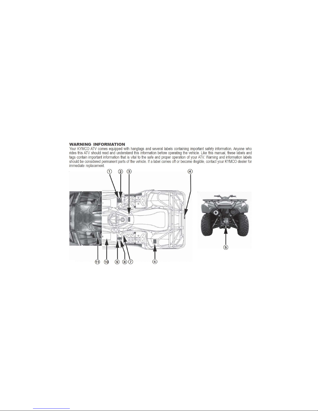
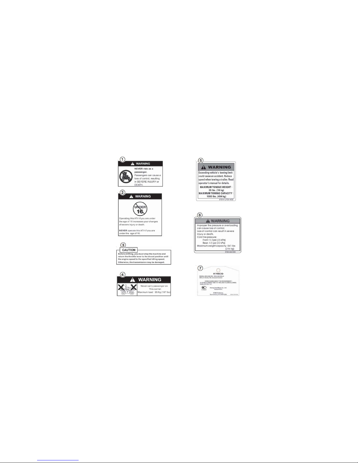
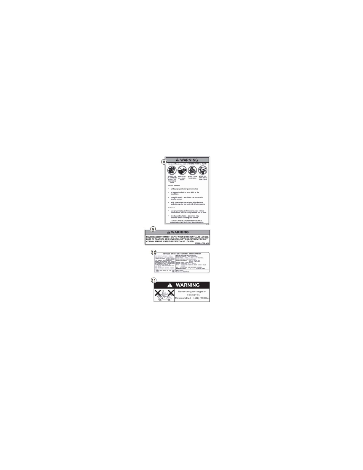
LOCATION OF THE WARNING AND SPECIFICATION LABELS
1
2
(US ONLY)
3
(US ONLY)

4
SAFETY INFORMATION
AN ATV IS NOT A TOY AND CAN BE HAZARDOUS TO OPERATE. An ATV handles differently from
other vehicles including motorcycles and cars. An accident can occur quickly, even during routine
maneuvers such as turning and riding on hills or over obstacles, if you fail to take proper precautions.
SEVERE INJURY OR DEATH can result if you do not follow these instructions:
Always avoid operating an ATV on any paved surfaces, including sidewalks, driveways, parking
lots and streets.
Never operate anATV on any public street, road or highway, even a dirt or gravel one.
Read this manual and all labels carefully and follow the operating procedures described.
Never operate anATV without proper training or instruction.
Beginners should receive training from a certified instructor.
Always follow the age recommendation:
- A child under 16 years old should never operate anATV with engine size greater than 90cc.
Never carry a passenger on an ATV.

5
Never operate anATV without wearing an approved motorcycle helmet that fits properly. You
should also wear eye protection (goggles or face shield), gloves, boots, long-sleeved shirt or
jacket, and long pants.
Never consume alcohol or drugs before or while operating this ATV.
Never operate at speeds too fast for your skills or the conditions.Always go at a speed that is
proper for the terrain, visibility and operating conditions, and your experience.
Never attempt wheel, jump, or other stunt.
Always inspect yourATV each time you use it to make sure it is in safe operating condition. Always
follow the inspection and maintenance procedures and schedules described in this manual.
Always keep both hands on the handlebars and both feet on the footboards of the ATV during
operation.
Always go slowly and be extra careful when operating on unfamiliar terrain.Always be alert to
changing terrain conditions when operating the ATV.
Always follow proper procedures for turning as described in this manual. Practice turning at low
speeds before attempting to turn at faster speeds. Do not turn at excessive speed.
Never operate on excessively rough, slippery or loose terrain until you have learned and practiced
the skills necessary to control the ATV on such terrain.Always be especially cautious on these
kinds of terrain.

6
Always follow proper procedures for climbing hills as described in this manual. Check the terrain
carefully before you start up any hill. Never climb hills with excessively slippery or loose surfaces.
Shift your weight forward. Never open the throttle suddenly. Never go over the top of a hill at high
speed.
Never operate theATV on hills too steep. Practice on smaller hills before attempting larger hills.
Always use proper procedures if you stall or roll backwards when climbing a hill. To avoid stalling,
maintain a steady speed when climbing a hill. If you stall or roll backwards, follow the special
procedure for braking described in this manual. Dismount on the uphill side or to a side if pointed
straight uphill. Turn the ATV around and remount, following the procedure described in this
manual.
Always follow proper procedures for going down hills and for braking on hills as described in this
manual. Check the terrain carefully before you start down any hill. Shift your weight backward.
Never go down a hill at high speed. Avoid going down hill at an angle that would cause the vehicle
to lean sharply to one side. Go straight down the hill where possible.
Always follow proper procedures for crossing the side of a hill as described in this manual. Avoid
hills with excessively slippery or loose surfaces. Shift your weight to the uphill side of the ATV.
Never attempt to turn theATV around on any hill until you have mastered the turning technique
described in this manual on level ground. Avoid crossing the side of a steep hill if possible.

POTENTIAL HAZARD
WHAT CAN HAPPEN
HOW TO AVOID THE HAZARD
Improper handling of gasoline.
Gasoline can catch fire and you could be
burned.
Always turn off the engine when refueling.
Do not refuel right after the engine has been
running and is still very hot.
Do not spill gasoline on the engine or exhaust
pipe/muffler when refueling.
Never refuel while smoking, or while in the
vicinity of sparks, open flames, or other
sources of ignition such as the pilot lights of
water heaters and clothes dryers.
WHAT CAN HAPPEN
HOW TO AVOID THE HAZARD
Gasoline is poisonous and can cause injuries.
If you should swallow some gasoline or inhale
a lot of gasoline vapor, or get some gasoline in
your eyes, see your doctor immediately.
If gasoline spills on your skin, wash with soap
and water. If gasoline spills on your clothing,
change your clothes.
7
WARNING

8
POTENTIAL HAZARD
Starting or running the engine in a closed
area.
WHAT CAN HAPPEN
Exhaust fumes are poisonous and may
cause loss of consciousness and death
within a short time.
HOW TO AVOID THE HAZARD
Always operate your machine in an area
with adequate ventilation.
WARNING
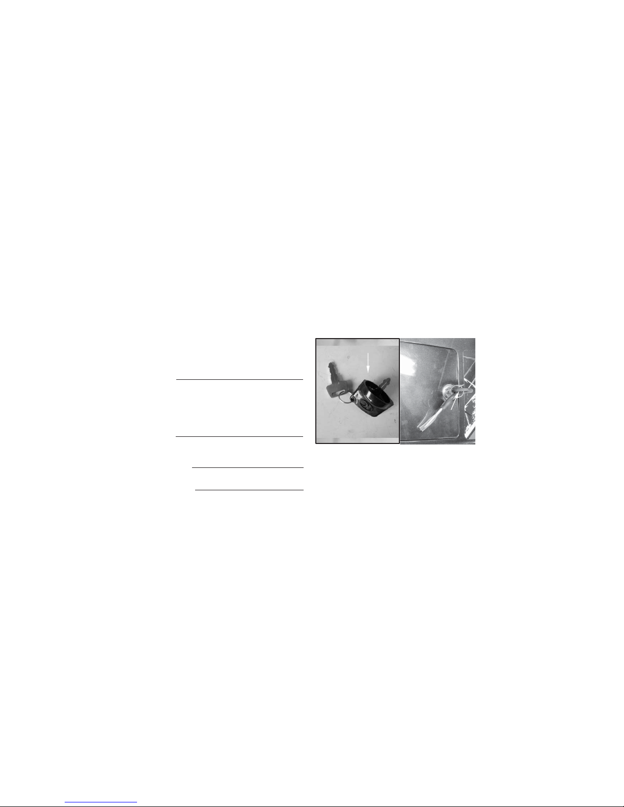
KEYS IDENTIFICATION NUMBER
The keys identification number is stamped on
the hang tag as shown in the following
illustration.
DESCRIPTION AND MACHINE IDENTIFICATION
(1) Ignition switch keys
(2) Right storage compartment lock and open keys
IDENTIFICATION NUMBER RECORDS
Record the keys identification number, frame
serial number and engine serial number
information for assistance when order
replacement parts.
IGNITION SWITCH KEY NO.
RIGHT STORAGE COMPARTMENT
LOCK AND OPEN KEY NO.
FRAME NO.
ENGINE NO.
(1)
(2)
9
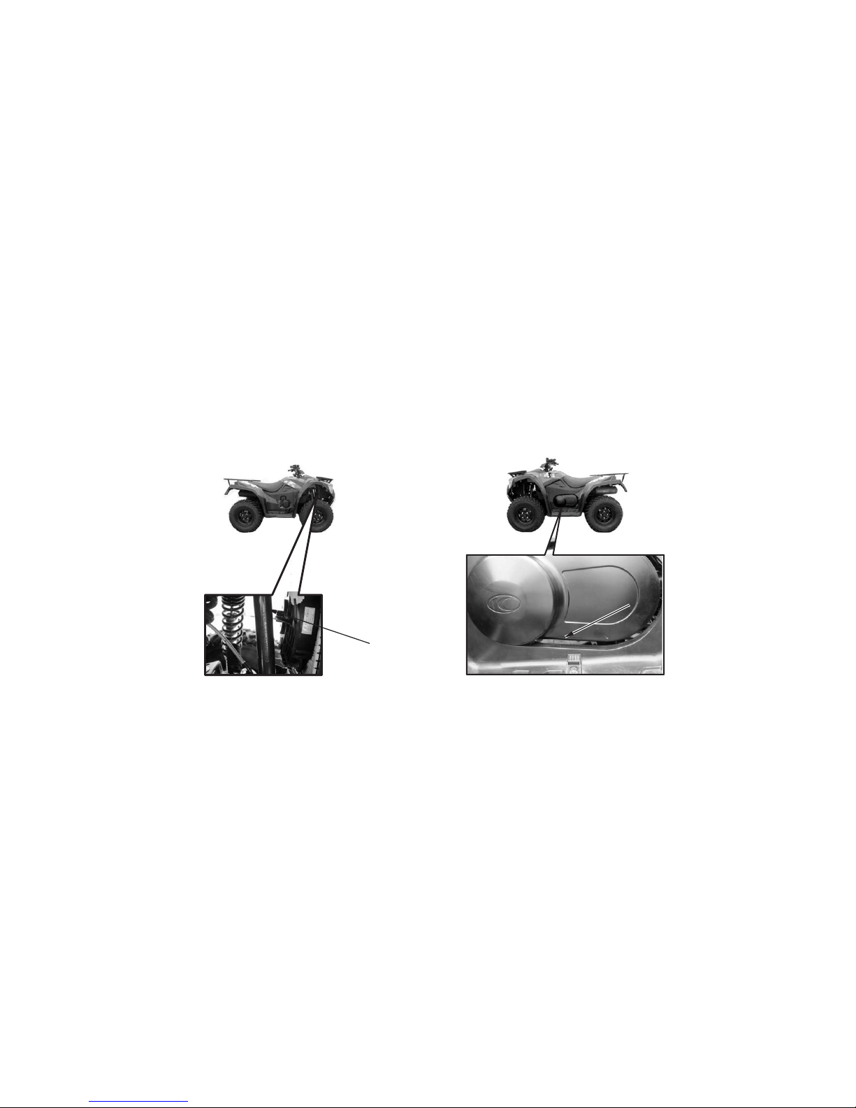
ENGINE SERIAL NUMBER
The engine serial number is stamped on the left
crankcase.
10
(1) Engine serial number
FRAME SERIAL NUMBER
The frame serial number is stamped on the
front of the frame.
(1) Frame serial number
(1)
(1)

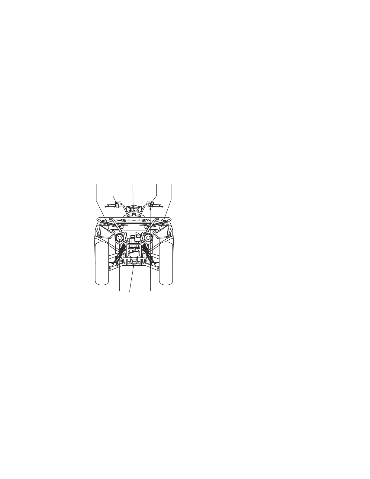
(01) Rear brake lever
(03) Front brake lever
(02) Headlights/Position lights
11
PARTS LOCATION
(01)(02)(02)(03)
NOTE: Your scooter may differ slightly in appearance from the images in this manual.
12
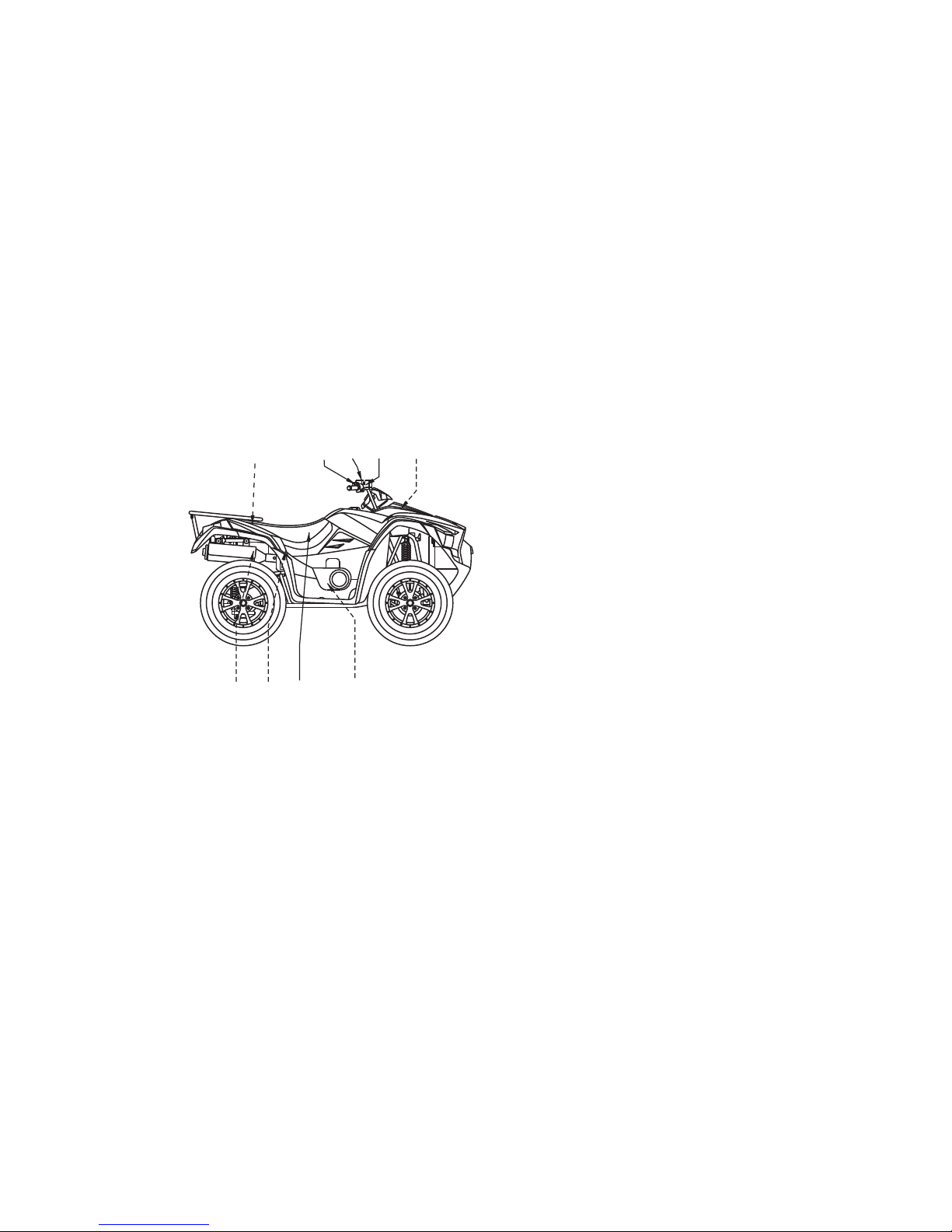
(04) Taillights/Brake lights
(05) 2WD/4WD select switch and differential lock switch
Headlight dimmer switch
Starter button
Engine Stop Switch
(08) Spark arrester
(09) Trailer hitch
(10) Throttle lever
(06) Instrument and indicators
(07)
(06)(04) (04)
(08) (09)
(07) (05)
(10)
NOTE: Your scooter may differ slightly in appearance from the images in this manual.
13
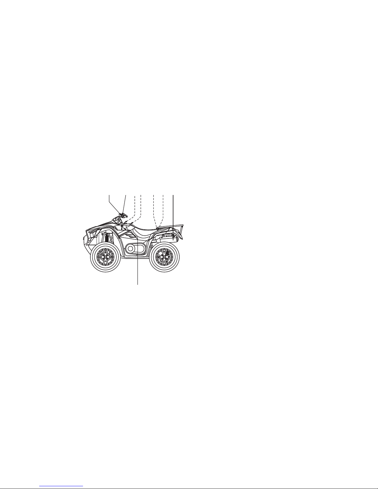
(11) Reservoir water tank
(12) Front brake fluid reservoir
(13) Right rearview mirror(Optional)
(14) Seat
Brake pedal fluid reservoir
Seat lock lever
Oil level inspection window
(18) Tool storage
(19) Left rearview mirror(Optional)
(15)
(16)
(17)
(16)
(17)(18)
(11)(12)
(13) (19)
(14)(15)
NOTE: Your scooter may differ slightly in appearance from the images in this manual.
14
(20)
) Battery/Fuse
(22) Tool kit
(23) Fuel pump
(24)
(25) Rear brake fluid reservoir
(26) Accessory socket seat
(27)
Exhaust system
(21
Left rearview mirror(Optional)
Drive select lever
(24) (20)
(25) (21)(22)
(26)
(27)
(23)
NOTE: Your scooter may differ slightly in appearance from the images in this manual.

(28) Right footpeg
(29) Owner’s manual storage
(30) Ignition switch
(31) Left footpeg
(32) Rear cargo rack
(33) Fuel fill cap
(34) Rear brake pedal
(35) Flag pole bracket
(36) Front cargo rack
15
(34) (35)(33)
(29)
NOTE:
The machine you have purchased may differ
slightly from those shown in the figures of this
manual.
(30)
(32)
(28)(31)
(36)
CONTROL FUNCTIONS
16
IGNITION SWITCH
ON :
Functions of the respective switch positions
are as follows:
The key can not be removed.
The engine can be started.
OFF:
"“:
All electrical circuits are switched off . The key
can be removed in this position.
All electrical circuits are switched on.
The ignition switch is ON while the position
light and taillight will light.
All electrical circuits are switched on.
The engine can be started.
The key can not be removed.
(2)
OFF
ON
(1)
(1) Ignition switch (2) Key
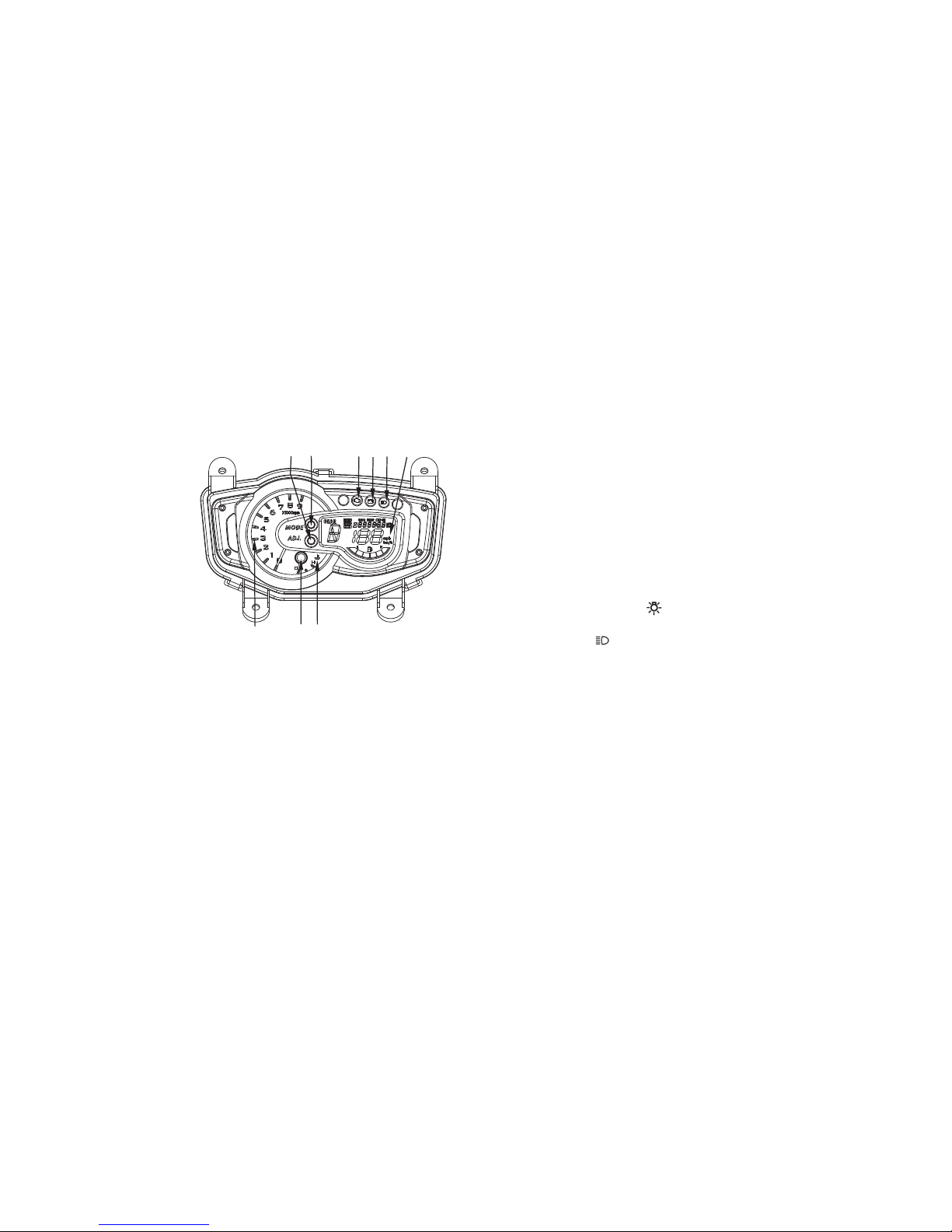
(1) Multi-function display
(2)
(4) ADJ
(5)
(6)
High beam indicator
(3) Coolant temperature warning indicator
button
MODE button
Battery low voltage indicator light
(7) CELP indicator
(8) Coolant temperature gauge
(9) T
achometer
(1) Multi-function display
The display includes the following functions:
Speedometer
Odometer/Tripmeter
Digital clock
4WD indicator/EFI system electric parts fault indicator
Fuel gauge
Gear select display
(2) High beam indicator
The ignition switch is at the " " position, the high
beam indicator will light when the headlight switch to
select High beam ( )
(3) Coolant temperature warning indicator
When the coolant temperature reaches a
specified level, this indicator comes on to warn
that the coolant temperature is too hot. If the
indicator comes on during operation, stop the
engine as soon as it is safe to do so and allow the
engine to cool down for about 10 minutes.
Differential lock indicator
Engine running time
.
(2)
(3)
(4)(5)
(1)
(6)
(8)(9)
INSTRUMENTS AND INDICATOR
17
(7)

18
(4) ADJ button
This button is used to select ODO, TRIP A
and TRIP B.
This button is also used to adjust the time
and reset the tripmeter.
(5) Mode button
This button is used to select km/h, mph, km
and mile.
This button is also used to adjust the time
and reset the trip meter.
(6)
(7)
Battery voltage too low warning Indicator
While user starting the engine, if the battery
voltage is too low. The indicator will Bright light.
Reminded user wanted to charge or replace new
battery
.
CELP indicator
If flashing, it indicates that a fault has been
detected in the scooter’s FI or electrical system.
Requires immediate inspection by a KYMCO
dealer.
NOTE: The CELP indicator lights momentarily
when the scooter is turned ON before the engine is
running.
(8)Coolant temperature gauge
When the coolant temperature reaches a
specified level to H position, this gauge
comes on to warn that the coolant
temperature is too hot. If the indicator comes
on during operation, stop the engine as soon
as it is safe to do so and allow the engine to
cool down for about 10 minutes.
(9)Tachometer
Indicates the engine speed in the revolutions
per minute(RPM).

19
Multi-function display
(1) Speedometer
(2) 4WD/LOCK/ indicator
(3) Fuel gauge
(4) Odometer/Tripmeter
(5) Digital clock
(6) Gear select display
(7) Engine running time
(1) Speedometer
Shows riding speed in km/h or mph.
Press and hold MODE button for more than 2
seconds to select mph or km/h.
(4) (1)(2)
(3)
(5)
(6)
(7)

(2)-1 Differential lock indicator
(2)-2 4WD indicator
Shows the drive mode is in the 4WD.
Shows the drive mode isn’t in the 2WD.
(2)-3 EFI system electric parts fault indicator
Turn the ignition switch to "ON" position
The indicator will be lighting until the engine starting
If no failure code, the indicator would be turned off.
If the failure code happens, the indicator would be
turned on
The front axle is equipped with a lockable
differential that allows the operator to choose
between an open differential or a closed
differential in low traction situations.
If the differential is in lock manner.
The lock indicator will be activated.
20
(3) Fuel gauge
The fuel gauge shows the approximate fuel
supply available in a graduated display. The
normal operating fuel range is with the
section between the segment F and segment
E. When the segment E or the fuel indicator
(3) flashes, fuel will be low and you should
refill the tank as soon as possible.
(1)
(3)
(2)
(3) Fuel indicator(1) Segment F
(2) Segment E
(2)-1
(2)-2
(2)-3
21
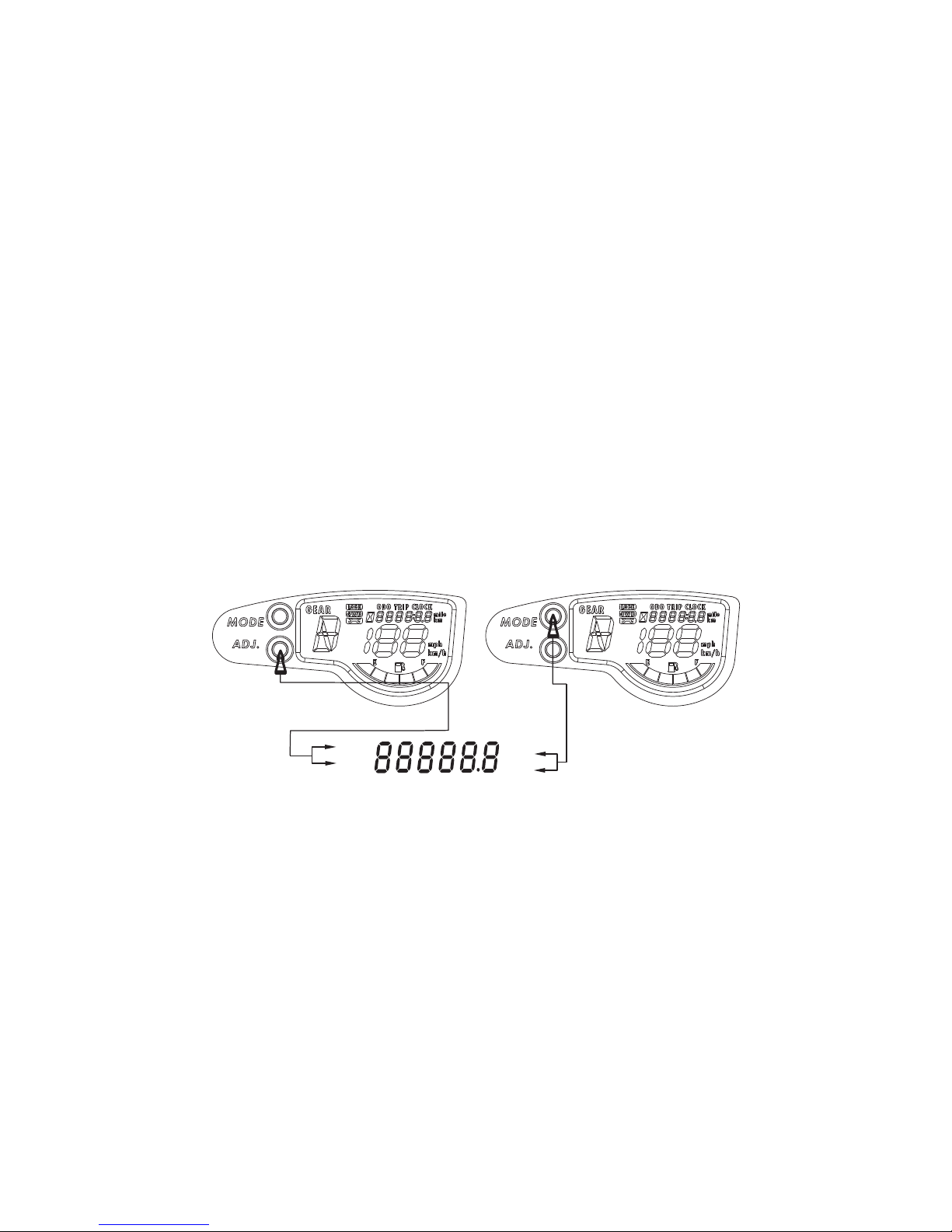
(4) Odometer/Tripmeter
The odometer shows the total mileage in Km or in mph.
The tripmeter shows the trip distance in Km or in mph.
There is tripmeters.
Press and hold SET button for more than 2 seconds to select ODO, TRIP
Press and hold MODE button for more than 2 seconds to select mph or km.
TRIP
ODO
mile
km
22
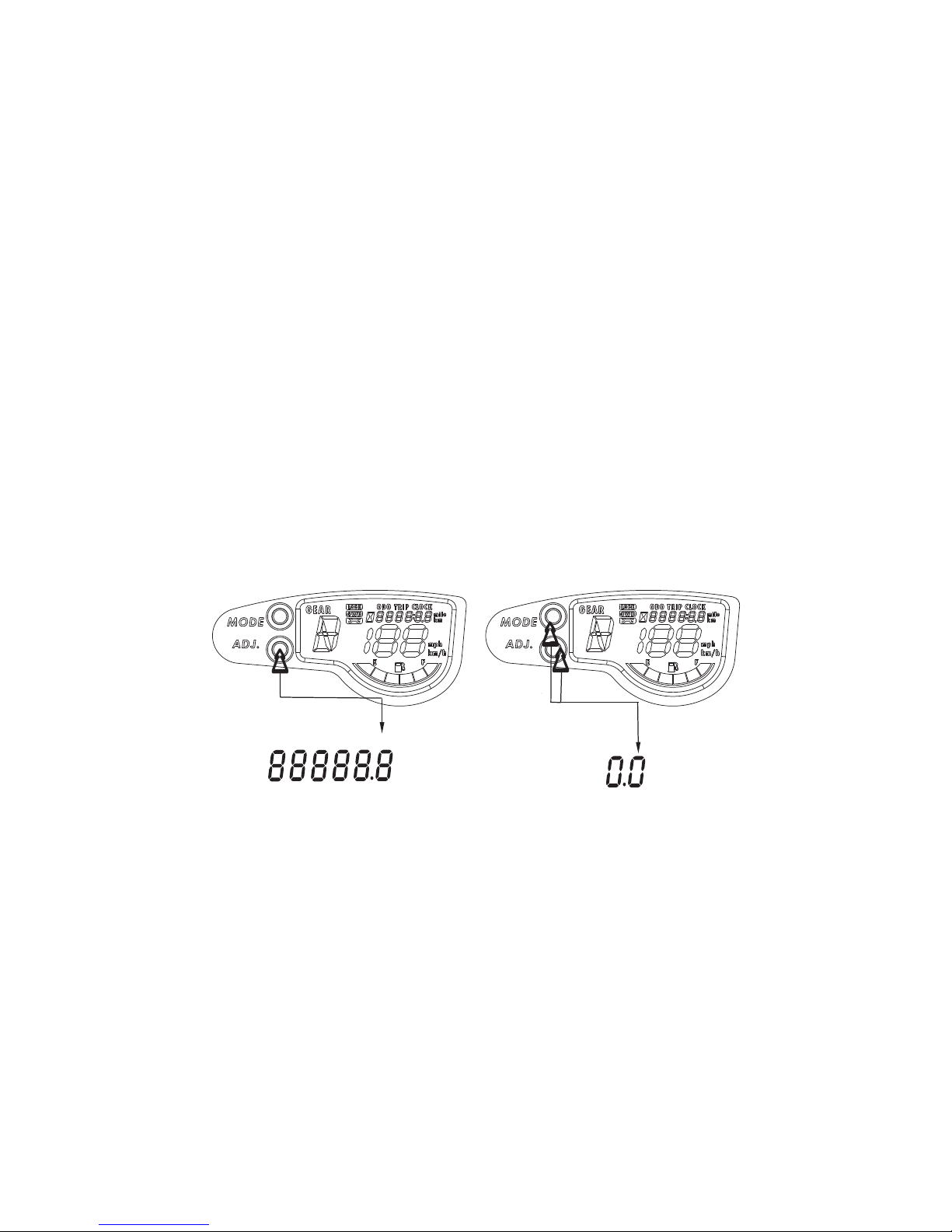
To reset tripmeter:
1. Press and hold SET button for more than 2
seconds to select tripmeter .
2. Press and hold both the MODE button and
SET button in the same time until the
tripmeter is reset.
TRIP
mile
km
TRIP
mile
km
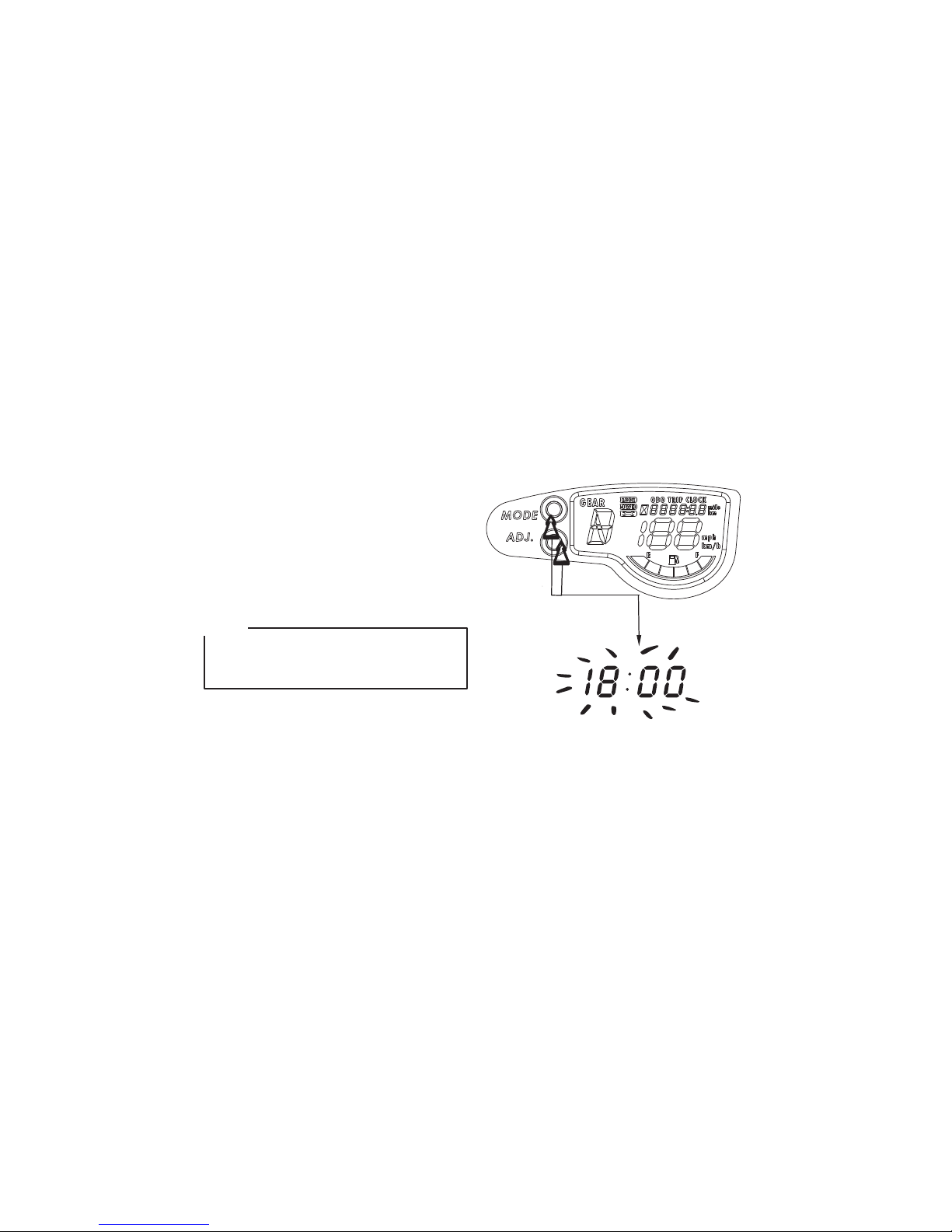
(5) Digital clock
Show the time (hours and minutes) while the
ignition is ON.
To adjust the time manually, proceed as follows:
1. Turn the ignition switch ON.
2. Press and hold SET button for more than 2
seconds to select ODO mode.
3. Press and hold both the MODE button and
SET button in the same time for more than 2
seconds. The clock will be set in the adjust
mode with the hour display flashing.
23
Digital clock can be adjust in ODO mode only,
never select TRIP A or TRIP B mode when you
want to adjust your digital clock.
NOTE:
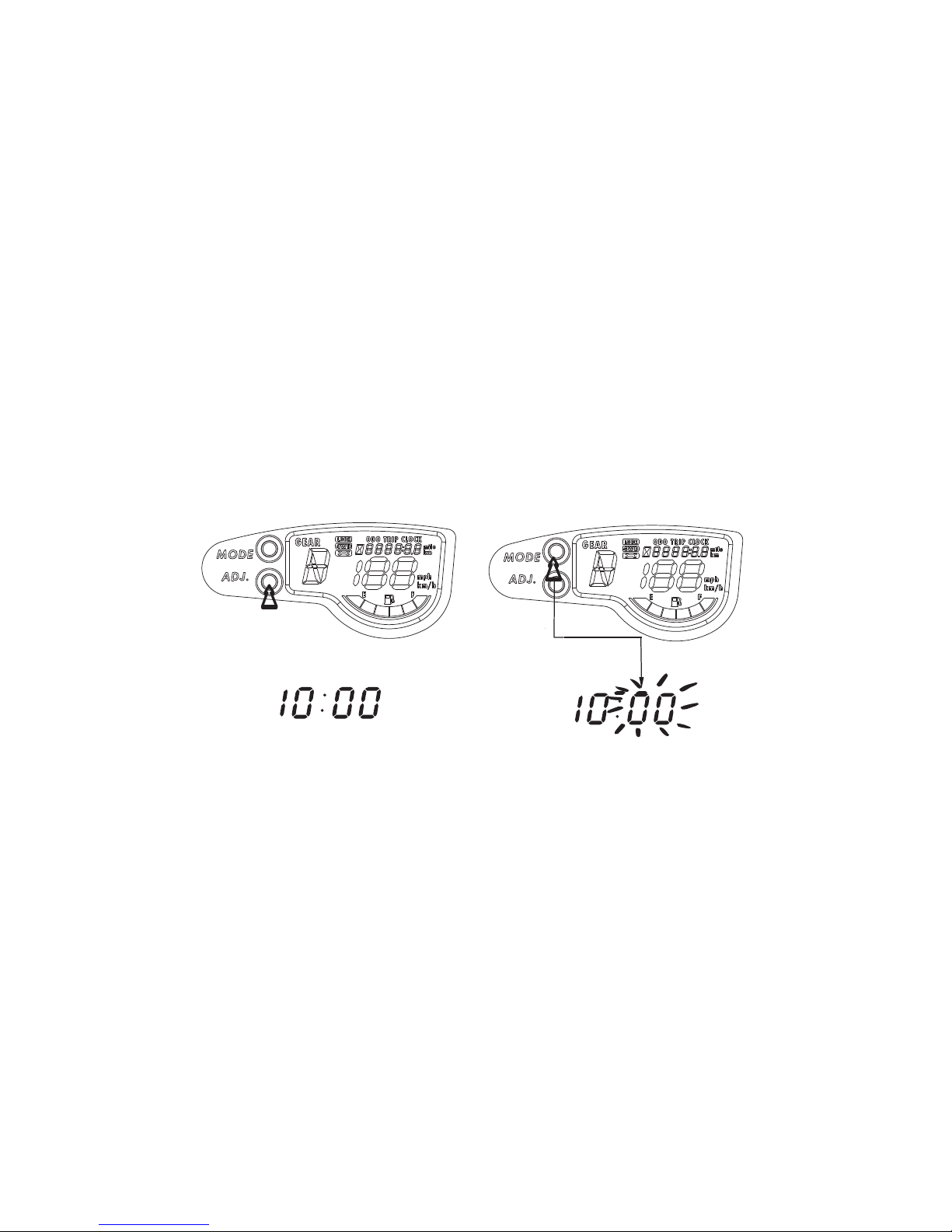
24
4. To set the hour, press the SET button until the
desired hour.
5. Press the MODE button, the minute display will
start flashing.
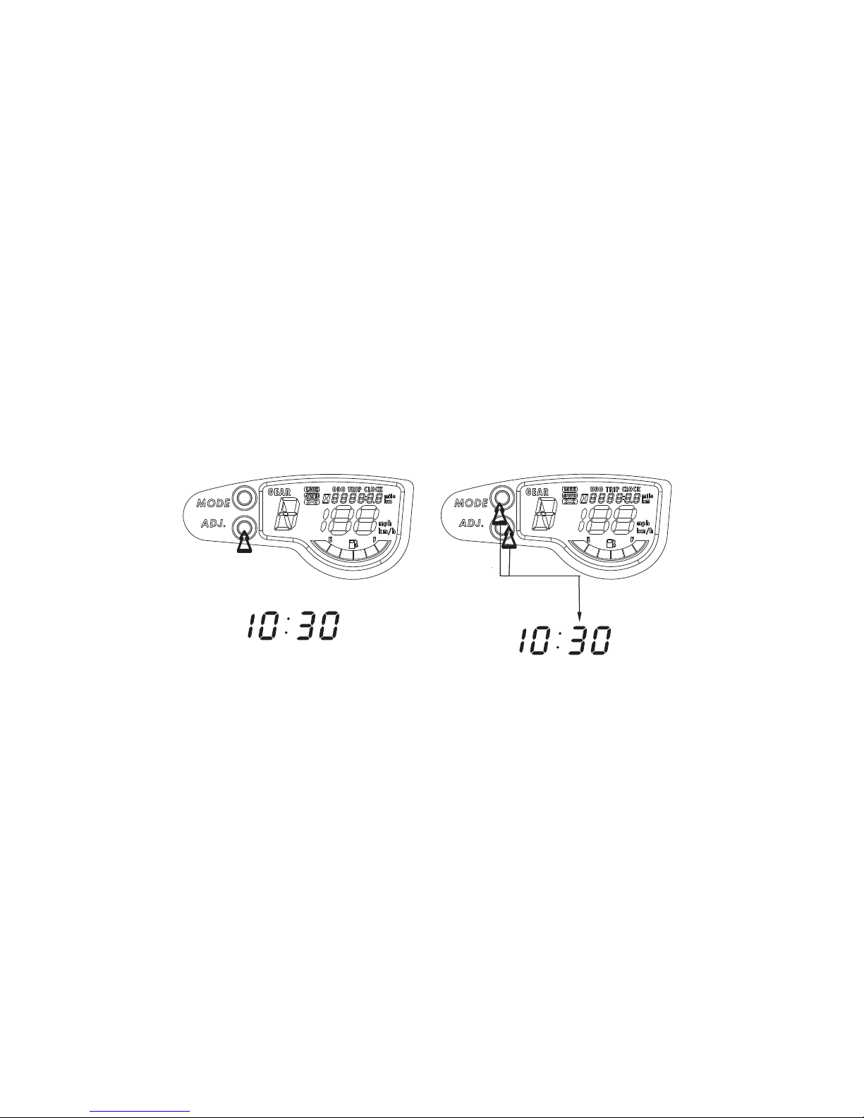
25
6. To set minute, press the SET button until the
desired minute.
7. To end the adjustment, Press both the MODE
button and SET button in the same time.
26
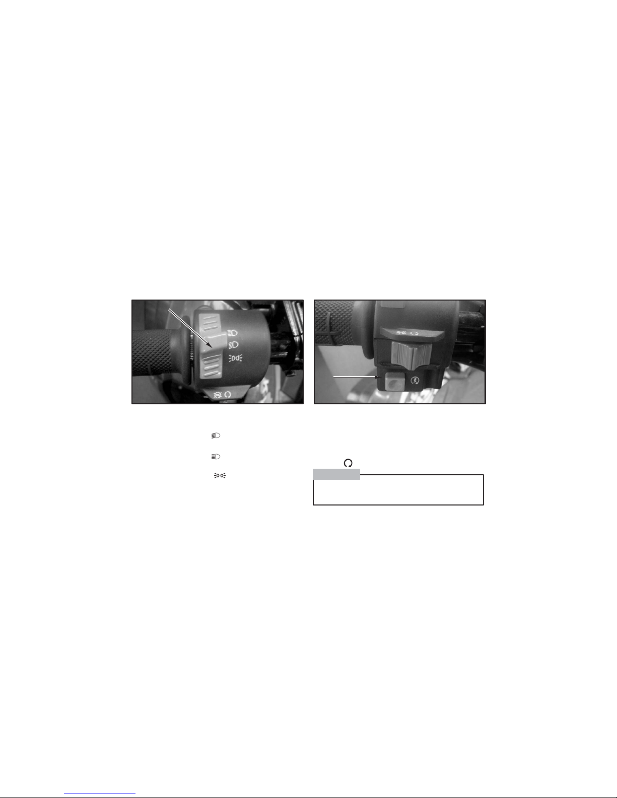
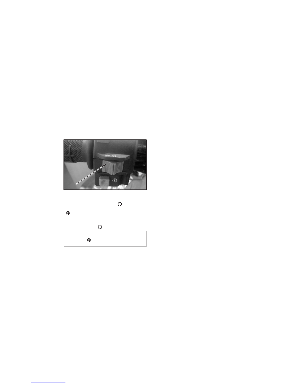
(1)
(1) Headlight switch
LEFT HANDLEBAR SWITCHES
Headlight dimmer switch
Turn the switch to the " " position to switch on
the low beam.
Turn the switch to the " " position to switch on
the high beam.
Turn the switch to the " " position to switch
off the headlight.
Stater button
To starter the engine, press the starter button,
with the transmission in neutral, the ignition
switch ON and the engine stop switch
At RUN ( )
(2)
(2) Starter button
See starting instructions prior to starting
engine (see page 58 for details).
CAUTION:
NOTE:
Your ATV may differ slightly in appearance
from the images in this manual.
NOTE:
Your ATV
may differ slightly in appearance
from
the images in this manual.
27
Engine stop switch
When the switch is in the RUN ( ) position, the
engine will operate. When the switch is in OFF
( ) position, the engine will not operate.
This switch is intended primarily as a safety or
emergency control, and it should normally
remain in the RUN ( ) position.
(3)
(3)Engine stop switch
If you stop your ATV by turning the engine stop
switch OFF ( ), be sure to turn the ignition
switch OFF to prevent battery discharge.
NOTE:
NOTE:
Your ATV may differ slightly in appearance
from the images in this manual.
NOTE:
Your ATV
may differ slightly in appearance
from
the images in this manual.
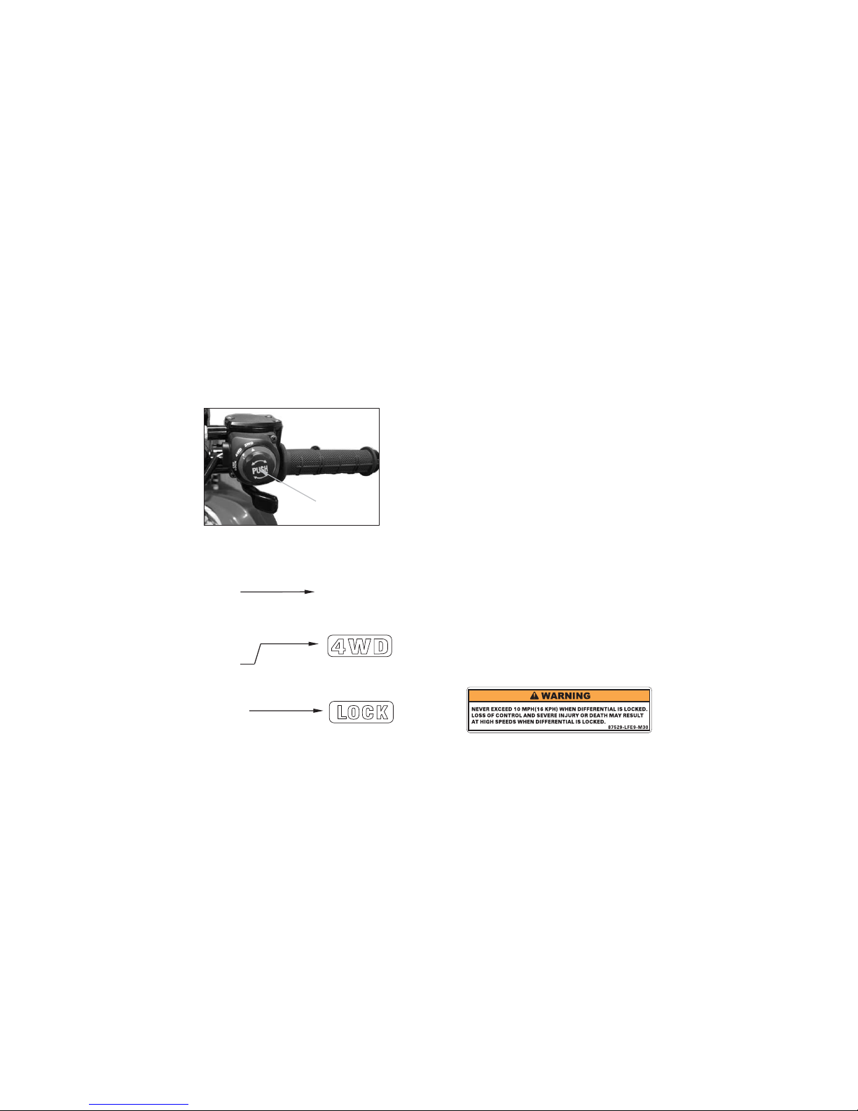
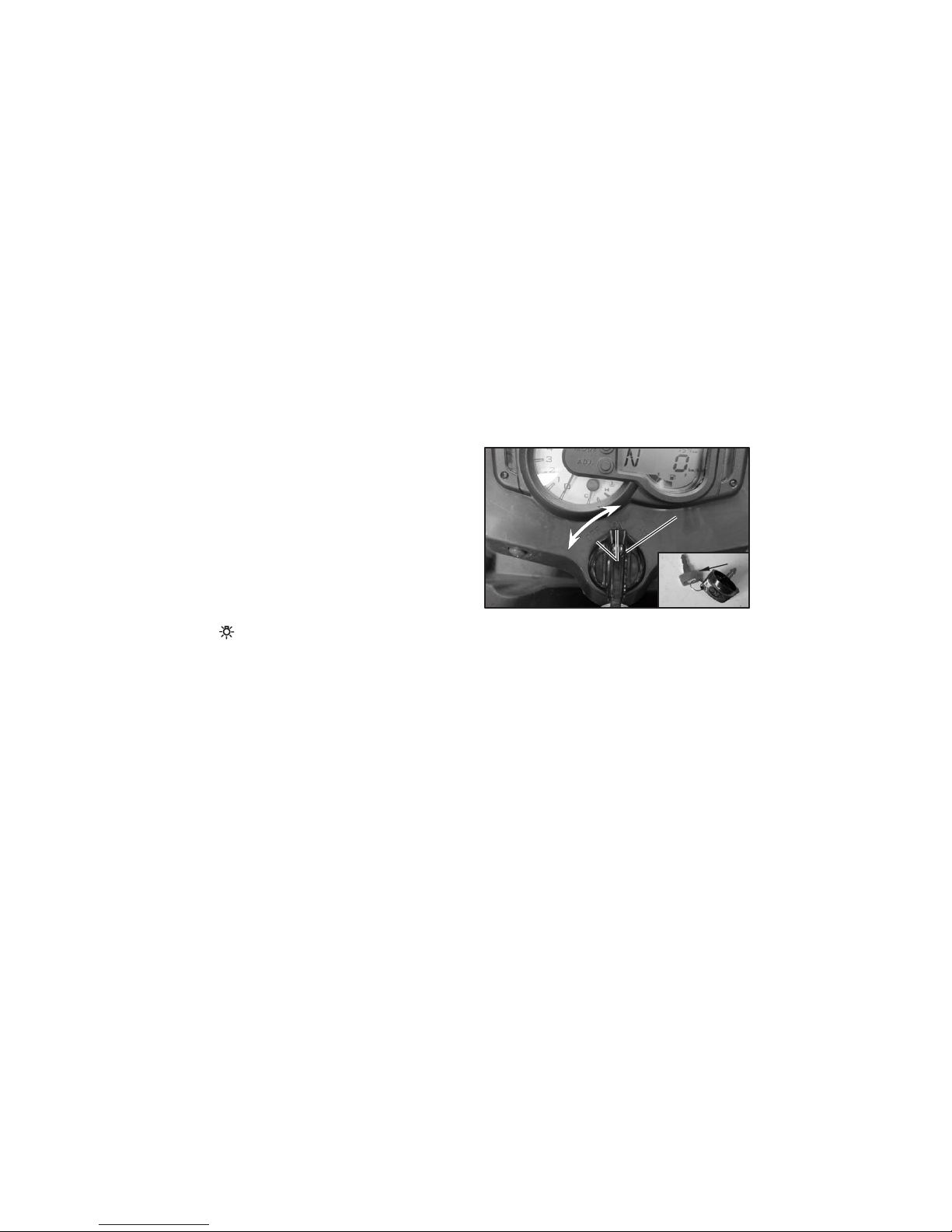
(1) 2WD/4WD select switch and differential
lock switch
RIGHT HANDLEBAR SWITCH
2WD/4WD select switch
This ATV is equipped with a 2WD/4WD select
switch, which permits a choice between the “2WD”
and “4WD” drive modes. Select a drive mode that is
suitable for your riding.
The 2WD/4WD select switch is located above the
throttle lever. To select the drive mode, push and
turning 2WD/4WD select switch to the desired
position.
To check your present drive mode, look at the Multifunction display.
28
2WD mode2WD mode
4WD mode4WD mode
In 2WD mode, meter
has no indication
Differential lock switch
The Differential lock switch is located above the
throttle lever.
The front axle is equipped with a lockable
differential that allows the operator to choose
between an open differential or a closed
differential in low traction situations.
If the differential is in lock manner.
In 4WD mode, meter should appear 4WD indicator,
then activate the lock switch, should appear 4WD
and LOCK indicator together.
In 2WD mode, meter has no indication, then activate
the lock switch, should appear 4WD and LOCK
indicator together.
(1)
4WD LOCK4WD LOCK

29
TO JUMP START YOUR VEHICLE
1.
2.
3.
4.
Remove the seat and locate the batteries.
Find the positive(+)and negative(-)terminals on
each battery.
Check that the jumper cables do not have lose
missing insulation. If they do, you could get a
shock. The vehicles could be damaged, too.
Before you connect the cables, here are some
basic things you should know. Positive(+)will go
to positive(+)and negative(-)will go to negative()or a metal engine part. Do not connect(+) to (-)
or you will get a short that would damage the
battery and maybe other parts, too.
Connect the red positive(+) cable to the
positive(+) terminal of the vehicle with the dead
battery. Use a remote positive(+) terminal if the
vehicle has one.
Don’t let the other end touch metal. It
to the positive(+) terminal of the good battery.
Connect
Use a remote positive(+) terminal if the vehicle
has one.
5.Now connect the black negative(-) cable to the
good battery’s negative(-) terminal .
Don’t let the other end touch anything until the
next step. The other end of the negative cable
go to the dead battery It goes to a
heavy unpainted metal part on the engine of the
vehicle with the dead battery.
Now start the vehicle with the good battery
and run the engine for a while.
Try to start the vehicle with the dead battery.
If won’t start after a few tries, it probably needs
service.
Remove the cables in reverse order to prevent
electrical shorting. Take care that the don’t
touch other or any other metal.
doesn’t
6.
7.
8.
.
NOTE:
If the other system isn’t a 12-volt system or
With a negative ground, both vehicles can
be damaged.
 Loading...