

KTM 690 Duke 2010 Repair manual
REPAIR MANUAL 2010
690 Duke EU
690 Duke AUS/UK
690 Duke JP
690 Duke USA
690 Duke R EU
690 Duke R AUS/UK
690 Duke R JP
Article no. 3206084en


INTRODUCTION 1
INTRODUCTION
Read this repair manual carefully and thoroughly before beginning work.
Only use ORIGINAL KTM SPARE PARTS.
The vehicle will only be able to meet the demands placed on it if the specified service work is performed regularly and properly.
This repair manual was written to correspond to the latest state of this series. We reserve the right to make changes in the interest of
technical advancement without at the same time updating this manual.
We shall not provide a description of general workshop methods. Likewise, safety rules that apply in a workshop are not specified here.
It is assumed that the repair work will be performed by a fully trained mechanic.
All specifications are non-binding. KTM Sportmotorcycle AG specifically reserves the right to modify or delete technical specifications, prices, colors, forms, materials, services, designs, equipment, etc., without prior notice and without specifying reasons, to adapt
these to local conditions, as well as to stop production of a particular model without prior notice. KTM accepts no liability for delivery
options, deviations from illustrations and descriptions, as well as misprints and other errors. The models portrayed partly contain special equipment that does not belong to the regular scope of delivery.
© 2010 KTM-Sportmotorcycle AG, Mattighofen Austria
All rights reserved
Reproduction, even in part, as well as copying of all kinds, is permitted only with the express written permission of the copyright
owner.
ISO 9001(12 100 6061)
According to the international quality management standard ISO 9001, KTM uses quality assurance processes that lead
to the maximum possible quality of the products.
Issued by: TÜV Management Service
KTM-Sportmotorcycle AG
5230 Mattighofen, Austria

CONTENTS 2
CONTENTS
MEANS OF REPRESENTATION ............................................ 5
IMPORTANT NOTES ............................................................ 6
LOCATION OF SERIAL NUMBERS ........................................ 7
Chassis number/type label (Duke R, 690 Duke EU,
690 Duke AUS/UK, 690 Duke JP) .................................... 7
Chassis number/type label (690 Duke USA) ....................... 7
Key number .................................................................... 7
Engine number................................................................ 7
Fork part number............................................................. 8
Shock absorber part number............................................. 8
MOTORCYCLE..................................................................... 9
Raising the motorcycle with the rear wheel stand................ 9
Taking the motorcycle off of the rear wheel stand ............... 9
Raising the motorcycle with the front wheel stand .............. 9
Taking the motorcycle off of the front wheel stand .............. 9
Raising the motorcycle with the work stand...................... 10
Removing the motorcycle from the work stand.................. 10
Starting ........................................................................ 11
Starting the motorcycle to make checks........................... 11
01/FORK, TRIPLE CLAMP.................................................. 12
Adjusting the compression damping of the fork ................ 12
Adjusting the rebound damping of the fork....................... 12
Bleeding the fork legs .................................................... 13
Removing fork legs ........................................................ 13
Installing the fork legs ................................................... 14
Servicing the fork .......................................................... 16
Disassembling the fork legs ............................................ 16
Checking the fork legs.................................................... 19
Assembling the fork legs (Duke)...................................... 21
Assembling the fork legs (Duke R)................................... 25
Checking the steering head bearing play .......................... 29
Adjusting the steering head bearing play.......................... 29
02/HANDLEBAR, INSTRUMENTS....................................... 30
Checking the play in the throttle cable............................. 30
Adjusting the play in the throttle cable ............................ 30
04/SHOCK ABSORBER, SWINGARM................................... 31
Adjusting the high-speed compression damping of the
shock absorber .............................................................. 31
Adjusting the low-speed compression damping of the
shock absorber .............................................................. 31
Adjusting the rebound damping of the shock absorber....... 32
Removing the shock absorber ......................................... 32
Installing the shock absorber .......................................... 33
Servicing the shock absorber .......................................... 34
Removing the spring ...................................................... 35
Disassembling the damper ............................................. 35
Disassembling the piston rod .......................................... 37
Checking the damper ..................................................... 38
Removing the heim joint ................................................ 39
Installing the heim joint ................................................. 39
Assembling the piston rod .............................................. 40
Assembling the damper.................................................. 41
Bleeding and filling the damper ...................................... 43
Filling the damper with nitrogen ..................................... 46
Installing the spring....................................................... 46
05/EXHAUST .................................................................... 48
Removing the exhaust system ......................................... 48
Installing the exhaust system.......................................... 48
06/AIR FILTER.................................................................. 50
Removing the air filter ................................................... 50
Installing the air filter .................................................... 50
07/FUEL TANK, SEAT, TRIM.............................................. 51
Opening filler cap.......................................................... 51
Closing filler cap ........................................................... 51
Removing the seat ......................................................... 51
Mounting the seat ......................................................... 51
Removing the fuel tank .................................................. 51
Installing the fuel tank................................................... 52
Reinstalling the fuel tank ............................................... 53
Positioning the fuel tank ................................................ 54
Removing the front spoiler.............................................. 54
Fitting front spoiler........................................................ 55
Checking the fuel pressure ............................................. 55
Changing the fuel filter .................................................. 56
09/FRONT WHEEL ............................................................ 58
Removing the front wheel............................................... 58
Installing the front wheel................................................ 58
Checking the tire pressure .............................................. 59
Checking the tire condition............................................. 59
Checking the brake discs................................................ 60
10/REAR WHEEL .............................................................. 61
Removing rear wheel...................................................... 61
Installing the rear wheel................................................. 61
Checking the chain tension ............................................ 62
Adjusting the chain tension ............................................ 62
Checking the chain, rear sprocket and engine sprocket...... 63
Cleaning the chain......................................................... 64
Checking the rear hub rubber dampers ............................ 64
11/WIRING HARNESS, BATTERY ....................................... 66
Removing the battery ..................................................... 66
Installing the battery...................................................... 67
Disconnecting negative (minus) cable of battery ............... 67
Reconnecting negative (minus) cable of battery ................ 68
Recharging the battery ................................................... 68
Checking the charging voltage ........................................ 69
Changing the main fuse ................................................. 69
Changing the fuses of individual power consumers............ 70
Adjusting the engine characteristic.................................. 71
13/BRAKE SYSTEM........................................................... 72
Checking the front brake linings...................................... 72
Changing the front brake linings ..................................... 72
Adjusting the basic position of the hand brake lever.......... 74
Checking the front brake fluid level ................................. 74
Adding front brake fluid ................................................. 75
Changing the front brake fluid ........................................ 75
Checking the rear brake linings ....................................... 76
Changing the rear brake linings....................................... 77
Checking the free travel of foot brake lever....................... 78
Adjusting the basic position of the foot brake lever ........... 79
Checking rear brake fluid level........................................ 79
Adding rear brake fluid .................................................. 80
Changing the rear brake fluid.......................................... 80
14/LIGHT SYSTEM, INSTRUMENTS ................................... 82
Setting kilometers or miles ............................................. 82
Setting the clock ........................................................... 82
Combination instrument - setting/resetting TRIP 1............ 82
Combination instrument - setting/resetting TRIP 2............ 82
Combination instrument - setting the wheel
circumference ............................................................... 83
Checking the low beam headlight adjustment................... 83
Adjusting the light range of the low beam headlight .......... 84
Checking the high beam headlight adjustment ................. 85
Adjusting the light range of the high beam headlight ........ 85

CONTENTS 3
Removing headlight mask with headlight ......................... 86
Installing the headlight mask with the headlight ............... 86
Changing the parking light bulb ...................................... 87
Changing the low beam bulb........................................... 88
Changing the turn signal bulb ......................................... 89
30/ENGINE....................................................................... 90
Removing the engine ..................................................... 90
Installing the engine ...................................................... 93
30/DISASSEMBLING THE ENGINE..................................... 98
Clamping engine into engine work stand .......................... 98
Draining the engine oil................................................... 98
Removing starter motor .................................................. 98
Removing valve cover..................................................... 98
Removing the alternator cover......................................... 99
Removing spacer ........................................................... 99
Removing gear position sensor ........................................ 99
Removing oil filter ......................................................... 99
Removing thermostat ................................................... 100
Setting engine to ignition top dead center...................... 100
Removing water pump wheel ........................................ 100
Removing clutch cover ................................................. 101
Removing spacer and spring ......................................... 101
Removing spark plug ................................................... 101
Removing timing chain tensioner .................................. 102
Removing camshafts.................................................... 102
Removing cylinder head ............................................... 102
Removing piston (Duke) ............................................... 102
Removing piston (Duke R) ............................................ 103
Removing rotor............................................................ 103
Removing timing chain rails ......................................... 104
Removing timing chain and timing chain sprocket .......... 104
Removing crankshaft position sensor ............................. 105
Removing clutch cage.................................................. 105
Removing primary gear................................................. 106
Removing starter drive ................................................. 106
Removing shift shaft.................................................... 107
Removing shift drum locating ....................................... 107
Removing locking lever ................................................ 107
Removing oil pumps .................................................... 107
Removing left engine case (Duke) ................................. 108
Removing left engine case (Duke R) .............................. 108
Removing crankshaft and balancer shaft (Duke) ............. 109
Removing crankshaft and balancer shaft (Duke R) .......... 109
Removing transmission shafts....................................... 109
30/ENGINE - WORK ON INDIVIDUAL PARTS..................... 111
Work on the right section of the engine case .................. 111
Work on the left section of the engine case .................... 112
Work on the clutch cover.............................................. 114
Removing crankshaft bearing inner ring (Duke)............... 114
Removing crankshaft bearing inner ring (Duke R) ........... 114
Removing balancer shaft drive wheel (Duke) .................. 115
Removing balancer shaft drive wheel (Duke R) ............... 115
Changing the conrod bearing (Duke).............................. 115
Changing the conrod bearing (Duke R)........................... 117
Checking crankshaft run-out at bearing pin .................... 118
Installing balancer shaft drive wheel (Duke) ................... 118
Installing balancer shaft drive wheel (Duke R) ................ 119
Installing crankshaft bearing inner ring (Duke) ............... 120
Installing crankshaft bearing inner ring (Duke R) ............ 120
Measuring axial clearance of crankshaft and balancer
shaft .......................................................................... 120
Cylinder - Nikasil®coating ............................................ 121
Checking/measuring the cylinder................................... 121
Checking/measuring the piston (Duke)........................... 122
Checking/measuring the piston (Duke R)........................ 123
Checking piston ring end gap........................................ 123
Checking piston/cylinder mounting clearance ................. 124
Checking oil pumps for wear......................................... 124
Replacing autodecompressor ........................................ 124
Preparing timing chain tensioner for installation ............. 125
Checking timing assembly ............................................ 126
Removing rocker arm ................................................... 126
Changing camshaft bearing .......................................... 126
Removing valves.......................................................... 127
Checking valves........................................................... 128
Checking valve springs ................................................. 128
Checking valve spring retainer ...................................... 128
Checking cylinder head ................................................ 128
Installing valves .......................................................... 129
Installing rocker arm.................................................... 130
Dismantling antihopping clutch .................................... 130
Checking the clutch..................................................... 131
Preassembling antihopping clutch................................. 132
Checking shift mechanism ........................................... 133
Preassembling shift shaft ............................................. 133
Disassembling the main shaft ....................................... 134
Dismantling countershaft ............................................. 134
Checking the transmission............................................ 135
Assembling the main shaft ........................................... 136
Assembling countershaft .............................................. 137
Checking electric starter drive....................................... 138
Removing freewheel..................................................... 138
Checking freewheel...................................................... 139
Installing freewheel ..................................................... 139
30/ASSEMBLING THE ENGINE ........................................ 141
Installing transmission shafts ....................................... 141
Installing crankshaft and balancer shaft (Duke) .............. 142
Installing crankshaft and balancer shaft (Duke R) ........... 142
Installing left engine case (Duke) .................................. 143
Installing left engine case (Duke R)............................... 143
Installing oil pumps ..................................................... 144
Installing locking lever ................................................. 144
Installing shift drum locating ........................................ 145
Installing shift shaft..................................................... 145
Installing starter drive .................................................. 145
Installing primary gear ................................................. 146
Installing clutch cage (Duke) ........................................ 146
clutch cage, installing (Duke R) .................................... 147
Installing crankshaft position sensor.............................. 148
Installing timing chain and timing chain sprocket ........... 149
Installing timing chain rails .......................................... 149
Installing rotor............................................................. 149
Adjusting crankshaft position sensor distance................. 150
Setting engine to top dead center.................................. 150
Installing piston (Duke)................................................ 150
Installing piston (Duke R)............................................. 152
Installing cylinder head................................................ 153
Installing camshafts .................................................... 154
Installing timing chain tensioner ................................... 154
Checking valve clearance ............................................. 155
Adjusting valve clearance ............................................. 155
Installing spark plug .................................................... 156
Installing spacer and spring.......................................... 156

CONTENTS 4
Installing clutch cover.................................................. 156
Mounting water pump cover.......................................... 157
Installing thermostat.................................................... 157
Installing the oil filter .................................................. 157
Installing gear position sensor....................................... 158
Installing the spacer .................................................... 158
Installing oil screens.................................................... 159
Installing alternator cover ............................................. 159
Installing starter motor (Duke) ...................................... 160
starter motor, installing (Duke R) .................................. 160
Installing valve cover ................................................... 160
Taking engine off universal mounting rack ..................... 160
32/CLUTCH .................................................................... 161
Checking/rectifying the fluid level of the hydraulic
clutch ........................................................................ 161
35/WATER PUMP, COOLING SYSTEM .............................. 162
Draining the coolant .................................................... 162
Filling/bleeding the cooling system................................ 162
Checking the antifreeze and coolant level ...................... 163
Checking the coolant level............................................ 164
38/LUBRICATION SYSTEM .............................................. 166
Oil circuit ................................................................... 166
Checking the engine oil level ........................................ 166
Checking the engine oil pressure................................... 167
Changing the engine oil and filter, cleaning the oil
screens....................................................................... 168
Draining the engine oil................................................. 168
Removing the oil filter.................................................. 169
Installing the oil filter .................................................. 170
Cleaning the oil screens ............................................... 170
Refilling with engine oil ............................................... 171
Adding engine oil ........................................................ 171
39/IGNITION SYSTEM ..................................................... 173
Alternator - checking the stator winding......................... 173
Checking the spark plug connector................................ 173
Ignition coil - checking the secondary winding................ 174
41/THROTTLE VALVE BODY............................................. 175
Checking the basic setting of the motor drive ................. 175
Adjusting the basic setting of the motor drive................. 176
Removing EPT control unit holder ................................. 180
Installing EPT control unit holder.................................. 180
Removing rollover sensor.............................................. 181
Installing rollover sensor............................................... 181
Flashing the EFI control unit and/or the EPT control
unit............................................................................ 181
Requesting the enabling code....................................... 182
Coding the EFI control unit and/or EPT control unit ........ 183
TECHNICAL DATA - ENGINE ............................................ 185
Capacity - engine oil .................................................... 185
Capacity - coolant........................................................ 186
TECHNICAL DATA - TOLERANCE, WEAR LIMITS OF
ENGINE ......................................................................... 187
TECHNICAL DATA - ENGINE TIGHTENING TORQUES........ 189
TECHNICAL DATA - CHASSIS .......................................... 191
Lighting equipment ..................................................... 191
Capacity - fuel............................................................. 192
TECHNICAL DATA - FORK................................................ 193
Duke .......................................................................... 193
Duke R....................................................................... 193
TECHNICAL DATA - SHOCK ABSORBER ........................... 194
Duke .......................................................................... 194
Duke R....................................................................... 194
TECHNICAL DATA - CHASSIS TIGHTENING TORQUES ...... 196
CLEANING/PROTECTIVE TREATMENT .............................. 198
Cleaning the motorcycle ............................................... 198
Protective treatment for winter operation ....................... 199
STORAGE ....................................................................... 200
Storage....................................................................... 200
Putting into operation after storage ............................... 200
SERVICE PLAN ............................................................... 201
Service schedule ......................................................... 201
WIRING DIAGRAM .......................................................... 202
Page 1 of 10 (Duke) .................................................... 202
Page 2 of 10 (Duke) .................................................... 204
Page 3 of 10 (Duke) .................................................... 206
Page 4 of 10 (Duke) .................................................... 208
Page 5 of 10 (Duke) .................................................... 210
Page 6 of 10 (Duke) .................................................... 212
Page 7 of 10 (Duke) .................................................... 214
Page 8 of 10 (Duke) .................................................... 216
Page 9 of 10 (Duke) .................................................... 218
Page 10 of 10 (Duke) .................................................. 220
Page 1 of 10 (Duke R) ................................................. 222
Page 2 of 10 (Duke R) ................................................. 224
Page 3 of 10 (Duke R) ................................................. 226
Page 4 of 10 (Duke R) ................................................. 228
Page 5 of 10 (Duke R) ................................................. 230
Page 6 of 10 (Duke R) ................................................. 232
Page 7 of 10 (Duke R) ................................................. 234
Page 8 of 10 (Duke R) ................................................. 236
Page 9 of 10 (Duke R) ................................................. 238
Page 10 of 10 (Duke R) ............................................... 240
SUBSTANCES................................................................. 242
AUXILIARY SUBSTANCES................................................ 244
SPECIAL TOOLS.............................................................. 246
STANDARDS................................................................... 259
INDEX ............................................................................ 260

MEANS OF REPRESENTATION 5
Symbols used
The symbols used are explained in the following.
Indicates an expected reaction (e.g. of a work step or a function).
Indicates an unexpected reaction (e.g. of a work step or a function).
Identifies a page reference (more information is provided on the specified page).
Indicates information with more details or tips.
Indicates the result of a testing step.
Identifies a voltage measurement.
Identifies a current measurement.
Identifies a resistance measurement.
Formats used
The typographical and other formats used are explained below.
Specific name Indicates a proprietary name.
®
Name
Brand™ Identifies a trademark.
Identifies a protected name.
IMPORTANT NOTES 6
Warranty
The work prescribed in the service plan must only be carried out in an authorized KTM workshop and confirmed in the service record;
otherwise all warranty claims will be disregarded. No warranty claim can be met for damage resulting from manipulation and/or other
changes to the vehicle.
Fuel, oils, etc.
You should use the fuels, oils and greases according to specifications as listed in the repair manual.
Spare parts, accessories
Only use spare parts and accessories approved and/or recommended by KTM. KTM accepts no liability for other products and any
resulting damage.
You will find the current KTM PowerParts for your vehicle on the KTM website.
International KTM Website: http://www.ktm.com
Work rules
Special tools are necessary for certain tasks. The tools are not contained in the vehicle but can be ordered under the number in parentheses. Example: valve spring mounter (59029019000)
During assembly, non-reusable parts (e.g. self-locking screws and nuts, seals and seal rings, O-rings, pins, lock washers) must be
replaced by new parts.
If a thread lock (e.g. Loctite®) is used for screw connections, be sure to comply with the manufacturer's specific instructions on its
usage.
Parts that you want to reuse following repairs and servicing should be cleaned and checked for damage and wear. Change damaged or
worn parts.
Following repairs or servicing, the vehicle must be checked for roadworthiness.
Notes/warnings
Pay close attention to the notes/warnings.
Info
Various information and warning labels are affixed to the vehicle. Do not remove information/warning labels. If they are missing, you or others may not recognize potential hazards and may therefore be injured.
Grades of risks
Danger
Identifies a danger that will immediately and invariably lead to fatal or serious permanent injury if the appropriate measures
are not taken.
Warning
Identifies a danger that is likely to lead to fatal or serious injury if the appropriate measures are not taken.
Caution
Identifies a danger that may lead to minor injuries if the appropriate measures are not taken.
Note
Identifies a danger that will lead to considerable machine and material damage if the appropriate measures are not taken.
Warning
Identifies a danger that will lead to environmental damage if the appropriate measures are not taken.
Repair manual
– Read this repair manual carefully and thoroughly before beginning work. It contains useful information and tips that will help you
repair and service your motorcycle.
– This manual assumes that the necessary special KTM tools and workplace and workshop equipment are available.
LOCATION OF SERIAL NUMBERS 7
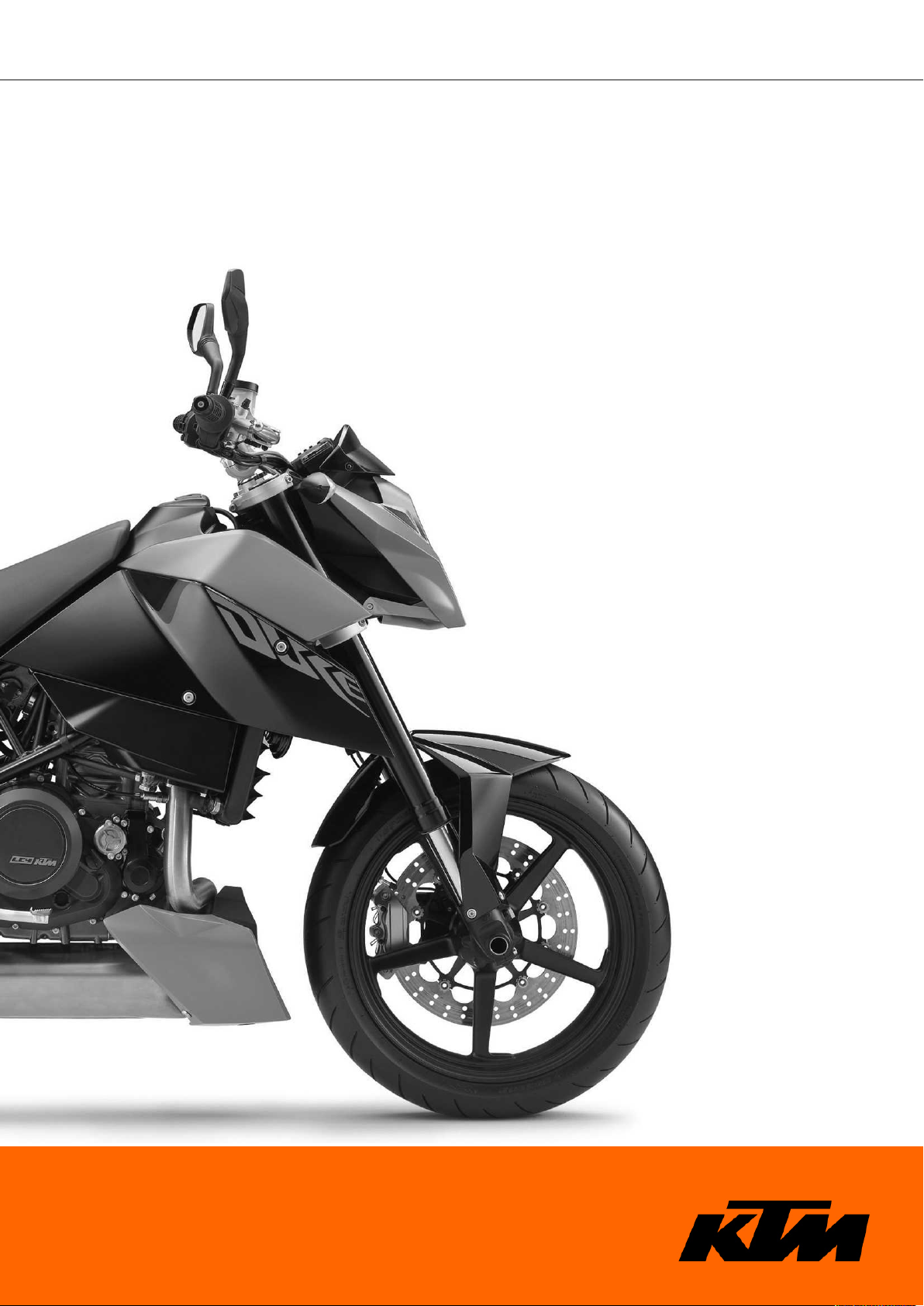
3.1Chassis number/type label (Duke R, 690 Duke EU, 690 Duke AUS/UK, 690 Duke JP)
The chassis number is stamped on the right of the steering head.
The type label is on the right of the frame behind the steering head.
500006-01
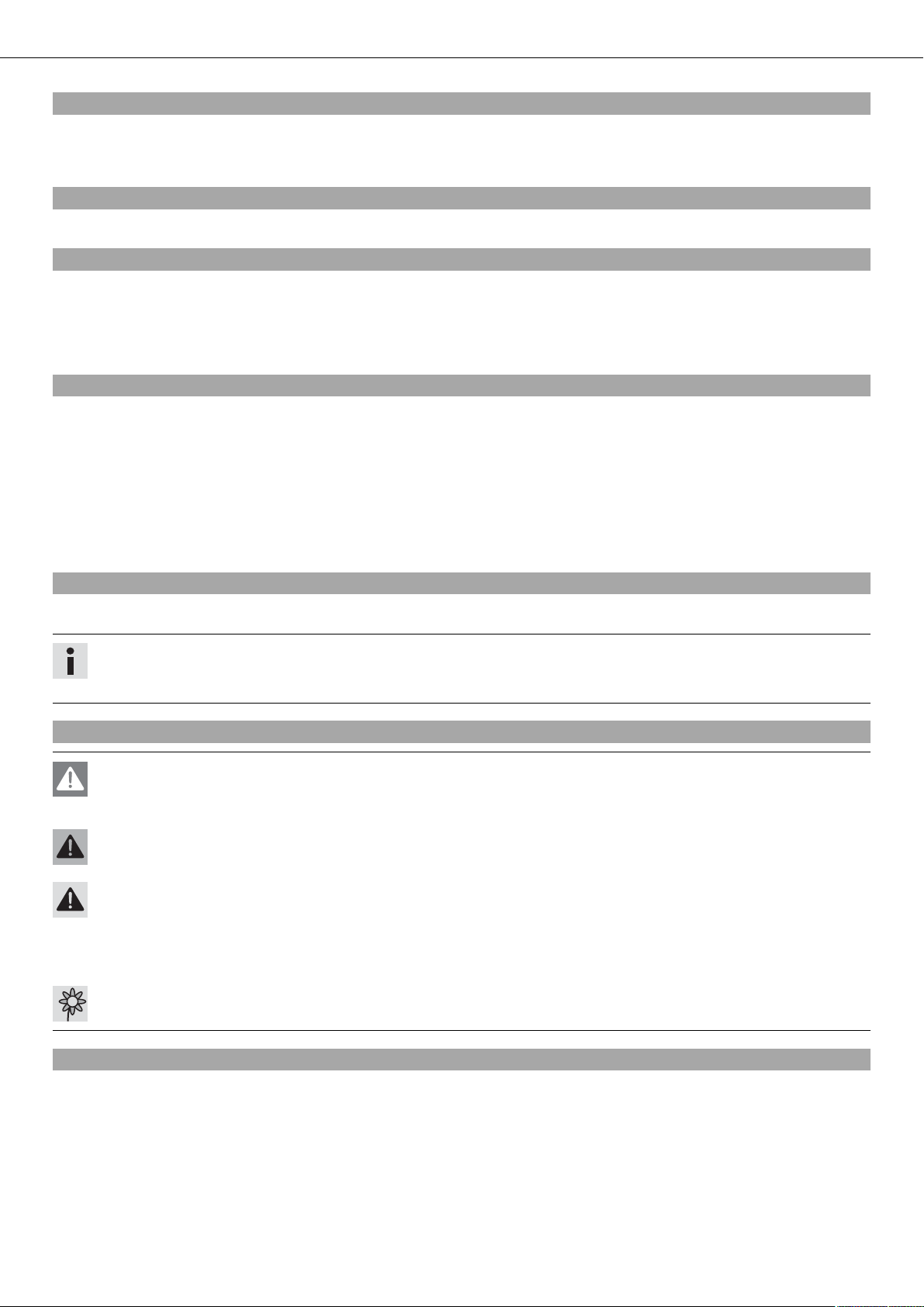
3.2Chassis number/type label (690 Duke USA)
The chassis number is stamped on the right of the steering head.
The USA type label is on the right of the frame behind the steering head.
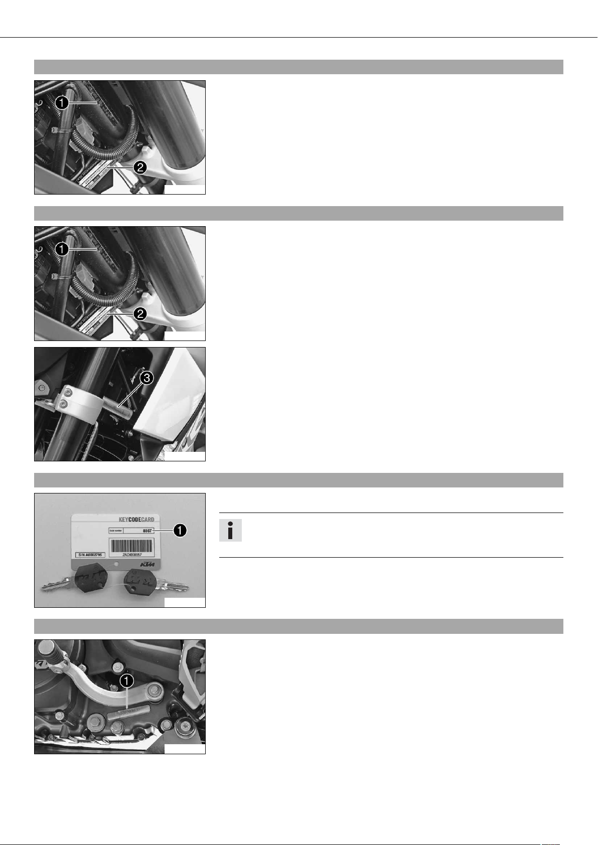
3.3Key number
500006-01
The Canada type label is on the right of the frame behind the steering head.
700218-01
The key number can be found on the KEYCODECARD.
Info
You need the key number to order a spare key. Keep the KEYCODECARD in a safe
place.
100179-10
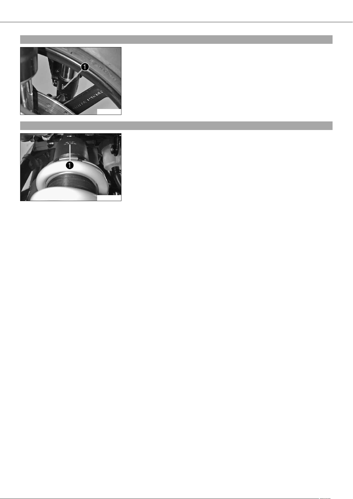
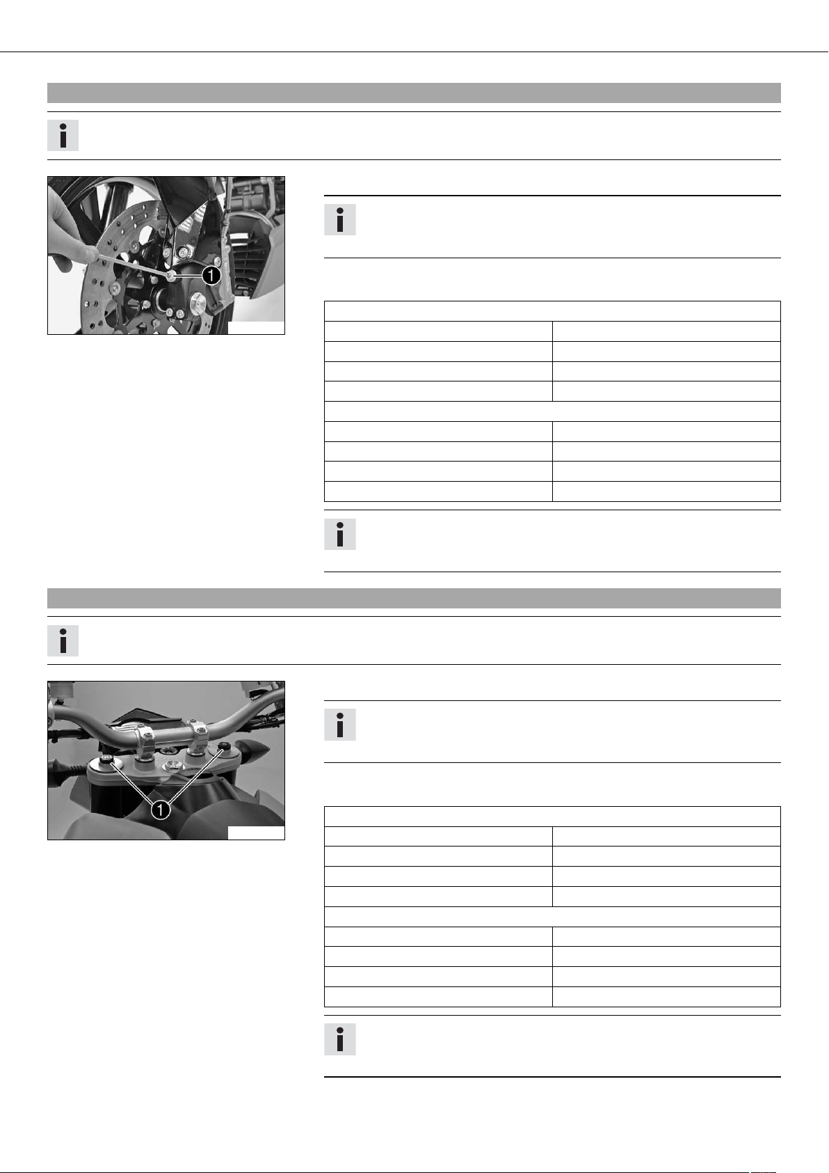
3.4Engine number
The engine number is stamped on the left side of the engine under the engine
sprocket.
700125-01
LOCATION OF SERIAL NUMBERS 8
3.5Fork part number
The fork part number is stamped on the inner side of the fork stub.
700126-01
3.6Shock absorber part number
The shock absorber part number is stamped on the top of the shock absorber above
the adjusting ring toward the rear.
700128-01

MOTORCYCLE 9
4.1Raising the motorcycle with the rear wheel stand
Note
Danger of damage The parked vehicle may roll away or fall over.
– Always place the vehicle on a firm and even surface.
– Insert the adapter into the rear wheel stand and screw into the swingarm on both
sides.
Adapter (61029055110) ( p. 248)
Rear wheel stand (61029055100) ( p. 248)
– Position the motorcycle upright, align the stand and raise the motorcycle.
700142-01
4.2Taking the motorcycle off of the rear wheel stand
Note
Danger of damage The parked vehicle may roll away or fall over.
– Always place the vehicle on a firm and even surface.
– Secure the motorcycle against falling over.
– Remove the rear wheel stand and lean the vehicle on the side stand.
4.3Raising the motorcycle with the front wheel stand
Note
Danger of damage The parked vehicle may roll away or fall over.
– Always place the vehicle on a firm and even surface.
– Raise the motorcycle with the rear wheel stand. ( p. 9)
– Move the handlebar to the straight-ahead position. Align the front wheel stand with
the fork legs using the adapters.
Front wheel stand (61029055300) ( p. 249)
Info
Always raise the rear of the motorcycle first.
– Raise the front of the motorcycle.
700141-01
4.4Taking the motorcycle off of the front wheel stand
Note
Danger of damage The parked vehicle may roll away or fall over.
– Always place the vehicle on a firm and even surface.
– Secure the motorcycle against falling over.
– Remove the front wheel stand.
MOTORCYCLE 10
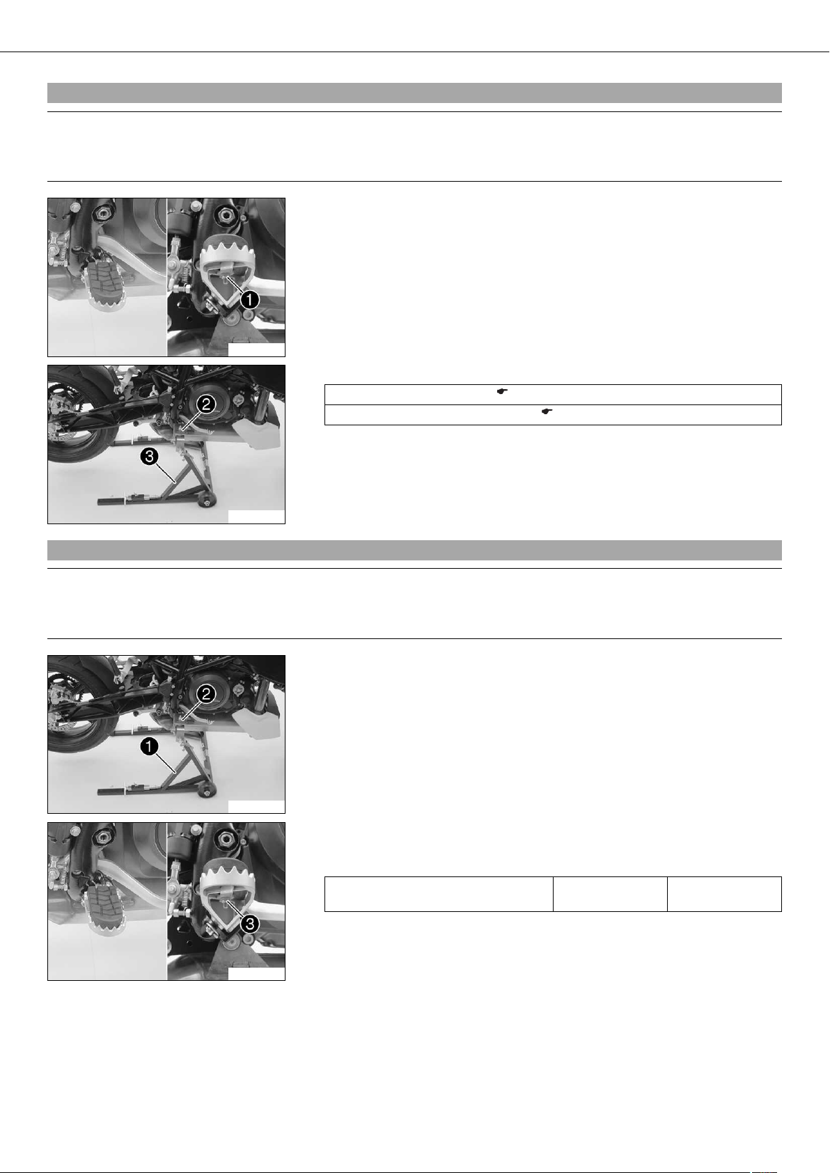
4.5Raising the motorcycle with the work stand
Note
Danger of damage The parked vehicle may roll away or fall over.
– Always place the vehicle on a firm and even surface.
– Remove the nuts on both sides.
– Take off the footrest rubber and holder.
300602-10
– Mount the special tool and .
Work stand (62529055000) ( p. 249)
Work stand adapter (75029036000) ( p. 251)
– Position the motorcycle upright, align the special tool and raise the motorcycle.
300603-10
4.6Removing the motorcycle from the work stand
Note
Danger of damage The parked vehicle may roll away or fall over.
– Always place the vehicle on a firm and even surface.
– Secure the motorcycle against falling over.
– Remove the special tool and .
300603-11
– Position the footrest rubbers with holders on both sides.
– Install nuts on both sides.
Guideline
Remaining nuts, chassis M6 15 Nm
(11.1 lbf ft)
300602-11
MOTORCYCLE 11
4.7Starting
Danger
Danger of poisoning Exhaust gases are poisonous and inhaling them may result in unconsciousness and/or death.
– When running the engine, always make sure there is sufficient ventilation, and do not start or run the engine in an enclosed
space without an effective exhaust extraction system.
Caution
Danger of accidents If the vehicle is operated with a discharged battery or without a battery, electronic components and safety
equipment may be damaged.
– Never operate the vehicle with a discharged battery or without a battery.
Note
Engine failure High engine speeds in cold engines have a negative effect on the service life of the engine.
– Always warm up the engine at low engine speeds.
– Turn the emergency OFF switch to the position .
– Switch on the ignition by turning the ignition key to the position .
After you switch on the ignition, you can hear the fuel pump working for about
2 seconds. At the same time, the function test of the combination instrument
is run.
– Shift gear to neutral.
The green idling speed indicator lamp N lights up.
– Press the electric starter button .
B00103-10
Info
Do not press the electric starter button until the function test of the combination instrument is finished.
When starting, DO NOT open the throttle. If you open the throttle during the
starting procedure, fuel is not injected by the engine management system
and the engine cannot start.
Press the starter for a maximum of 5 seconds. Wait for at least 5 seconds
before trying again.
This motorcycle is equipped with a safety start system. You can only start
the engine if the gearbox is in neutral or if the clutch is pulled when a
gear is engaged. If the side stand is folded out and you shift into gear and
release the clutch, the engine stops.
– Take the weight off the side stand and swing it back up with your foot as far as it
will go.
4.8Starting the motorcycle to make checks
Danger
Danger of poisoning Exhaust gases are poisonous and inhaling them may result in unconsciousness and/or death.
– When running the engine, always make sure there is sufficient ventilation, and do not start or run the engine in an enclosed
space without an effective exhaust extraction system.
Info
Press the starter for a maximum of 5 seconds. Wait for a least 5 seconds before trying again.
– Turn the emergency OFF switch to the position .
– Shift gear to neutral.
– Switch on the ignition.
– Press the electric starter button .
Info
Do not open the throttle.
B00103-10
01/FORK, TRIPLE CLAMP 12
5.1Adjusting the compression damping of the fork
Info
The hydraulic compression damping determines the fork suspension behavior.
– Turn adjusting screws clockwise until they stop.
Info
The adjusting screws are located at the bottom end of the fork legs.
Make the same adjustment on both fork legs.
– Turn back counterclockwise by the number of clicks corresponding to the fork type.
Guideline
Compression damping (Duke)
700146-01
Comfort 20 clicks
Standard 15 clicks
Sport 10 clicks
Full payload 10 clicks
Compression damping (Duke R)
Comfort 20 clicks
Standard 15 clicks
Sport 10 clicks
Full payload 10 clicks
Info
Turn clockwise to increase damping, turn counterclockwise to reduce suspension damping.
5.2Adjusting the rebound damping of the fork
Info
The hydraulic rebound damping determines the fork rebound behavior.
– Turn adjusting screws clockwise until they stop.
Info
The adjusting screws are located at the top end of the fork legs.
Make the same adjustment on both fork legs.
– Turn back counterclockwise by the number of clicks corresponding to the fork type.
Guideline
Rebound damping (Duke)
700145-01
Comfort 20 clicks
Standard 15 clicks
Sport 10 clicks
Full payload 10 clicks
Rebound damping (Duke R)
Comfort 25 clicks
Standard 20 clicks
Sport 15 clicks
Full payload 15 clicks
Info
Turn clockwise to increase damping; turn counterclockwise to reduce damping.
01/FORK, TRIPLE CLAMP 13
5.3Bleeding the fork legs
– Lean the motorcycle on the side stand.
– Remove bleeder screws briefly.
Any excess pressure escapes from the interior of the fork.
– Mount and tighten bleeder screws.
Info
Carry out this action on both fork legs.
100849-10
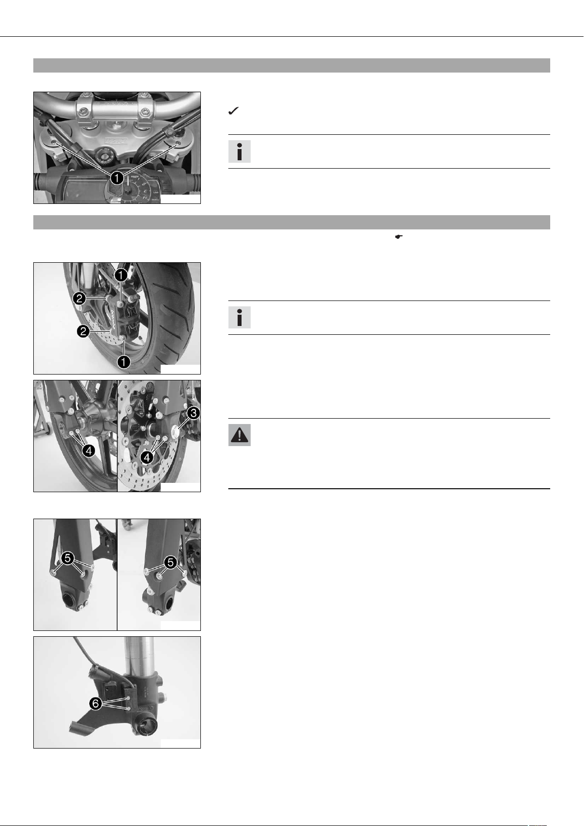
5.4Removing fork legs
– Raise the motorcycle with the work stand. ( p. 10)
– Tie the rear of the vehicle down.
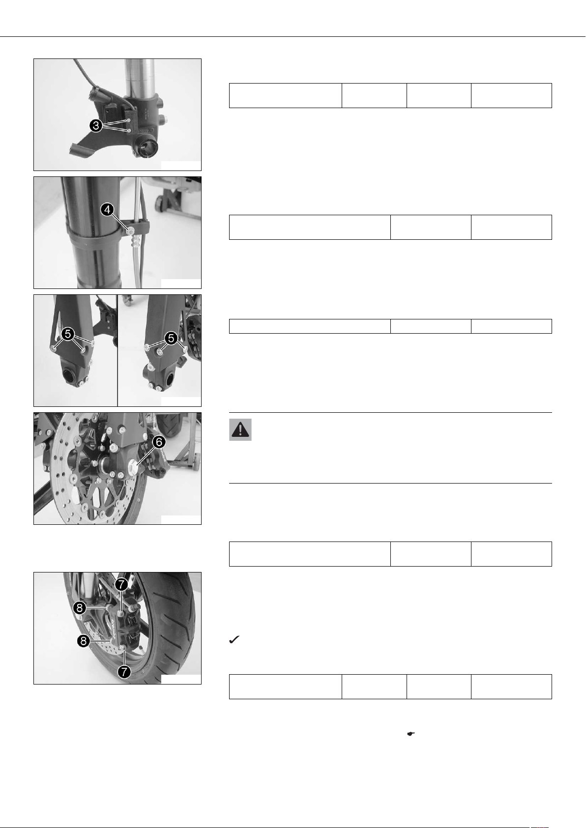
– Remove screws and spacers .
– Press back the brake linings with a light lateral tilting of the brake caliper on the
brake disc. Carefully pull the brake caliper backwards from the brake disc.
Info
Do not pull the hand brake lever while the brake caliper is removed.
200707-10
200708-10
200709-10
– Loosen screws and .
– Unscrew screw about 6 turns and press your hand on the screw to push the
wheel spindle out of the axle clamp. Remove screw .
Warning
Danger of accidents Reduced braking efficiency caused by damaged brake
discs.
– Always lay the wheel down in such a way that the brake disc is not dam-
aged.
– Holding the front wheel, withdraw the wheel spindle. Take the front wheel out of
the fork.
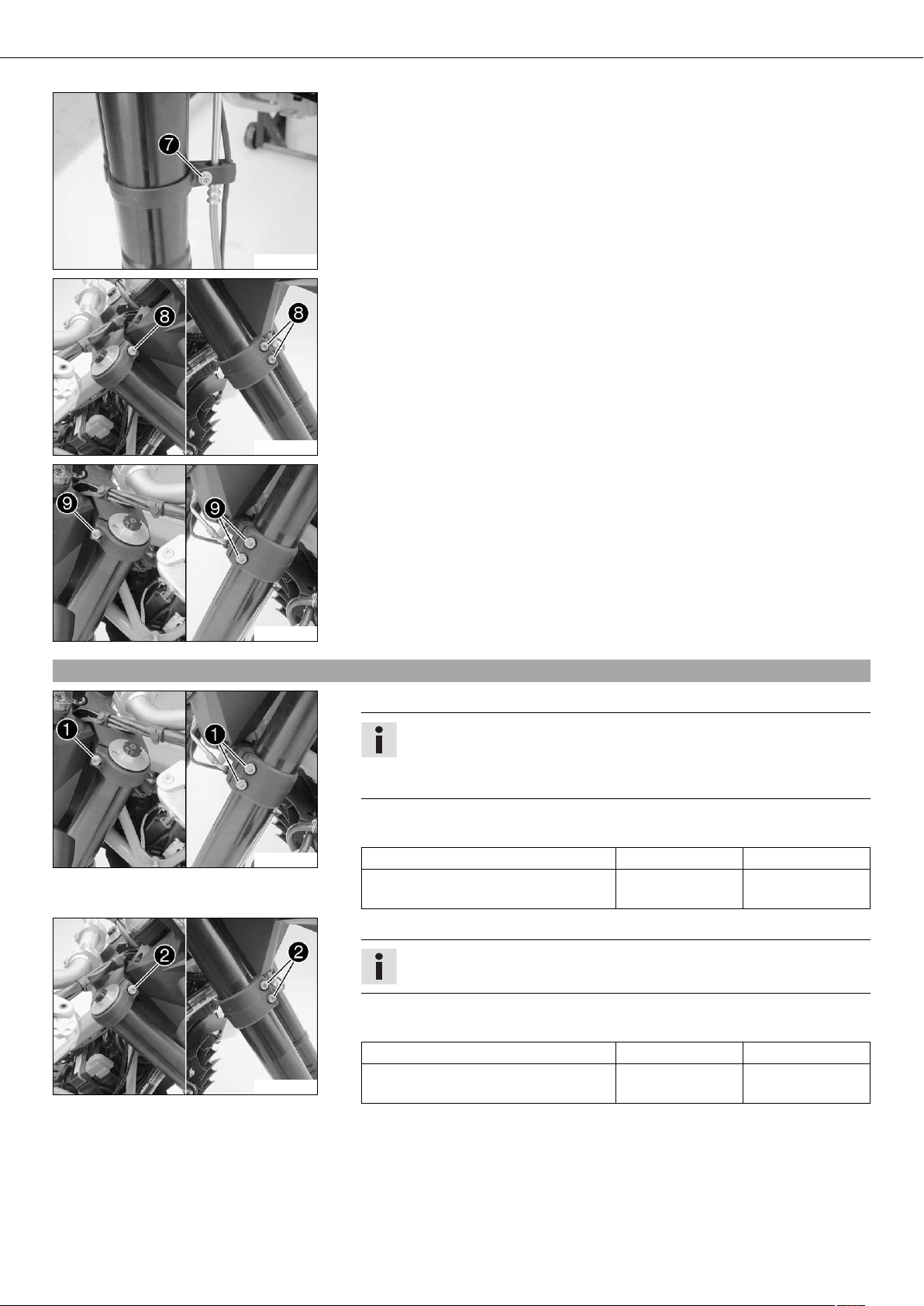
– Remove screws with the washers. Remove the splash protector.
– Remove the screws of the wheel speed sensor . Hang the wheel speed sensor to
one side.
– Loosen the cable binders.
200710-10
01/FORK, TRIPLE CLAMP 14
– Remove screw . Take the brake line and wiring harness out of the clamp.
200711-10
– Loosen the screws of the triple clamp. Remove the fork leg downwards.
200712-10
– Loosen the screws of the triple clamp. Remove the fork leg downwards.
5.5Installing the fork legs
200713-10
200713-11
200712-11
– Push the fork leg into the triple clamps.
Info
The bleeder screws must face forwards.
The topmost milled groove in the fork leg must be flush with the top edge of
the upper triple clamp.
– Tighten screws of the triple clamps.
Guideline
Screw, top triple clamp M8 12 Nm (8.9 lbf ft)
Screw, bottom triple clamp M8 15 Nm
(11.1 lbf ft)
– Push the fork leg into the triple clamps.
Info
The upper fork projection must be the same on both sides.
– Tighten screws of the triple clamps.
Guideline
Screw, top triple clamp M8 12 Nm (8.9 lbf ft)
Screw, bottom triple clamp M8 15 Nm
(11.1 lbf ft)
01/FORK, TRIPLE CLAMP 15
– Position the wheel speed sensor. Mount and tighten screws .
Guideline
200710-11
200711-11
Screw, wheel speed sensor M4 2 Nm
(1.5 lbf ft)
– Position the brake line, wiring harness and clamp.
– Mount and tighten screw .
Guideline
Screw, plastic clamp of brake line on
fork leg
– Position the splash protector. Mount and tighten screws with the washers.
Guideline
Remaining screws, chassis M6 10 Nm (7.4 lbf ft)
M5 2 Nm (1.5 lbf ft)
Loctite®243™
200709-10
200714-10
200707-11
Warning
Danger of accidents Reduced braking efficiency due to oil or grease on the
brake discs.
– Always keep the brake discs free of oil and grease, and clean them with
brake cleaner when necessary.
– Clean screw and the wheel spindle.
– Lift the front wheel into the fork, position it, and insert the wheel spindle.
– Mount and tighten screw .
Guideline
Screw, front wheel spindle M24x1.5 40 Nm
(29.5 lbf ft)
– Position the brake calipers and check that the brake linings are seated correctly.
– Mount screws with spacers but do not tighten.
– Operate the hand brake lever repeatedly until the brake linings are in contact with
the brake disc and there is a pressure point. Fix the hand brake lever in the activated position.
The brake caliper straightens.
– Tighten screws .
Guideline
Screw, front brake caliper M10x1.25 45 Nm
(33.2 lbf ft)
Loctite®243™
– Remove the fixation of the hand brake lever.
– Unload the rear of the vehicle.
– Remove the motorcycle from the work stand. ( p. 10)
01/FORK, TRIPLE CLAMP 16
– Pull the front brake and compress the fork powerfully a few times.
The fork legs straighten.
– Tighten screws .
Guideline
Screw, fork stub M8 15 Nm
(11.1 lbf ft)
200717-10
5.6Servicing the fork
Info
These operations are the same on both fork legs.
Condition
The fork legs have been removed.
– Disassemble the fork legs. ( p. 16)
– Check the fork legs. ( p. 19)
– Assemble the fork legs. ( p. 21)
201244-01
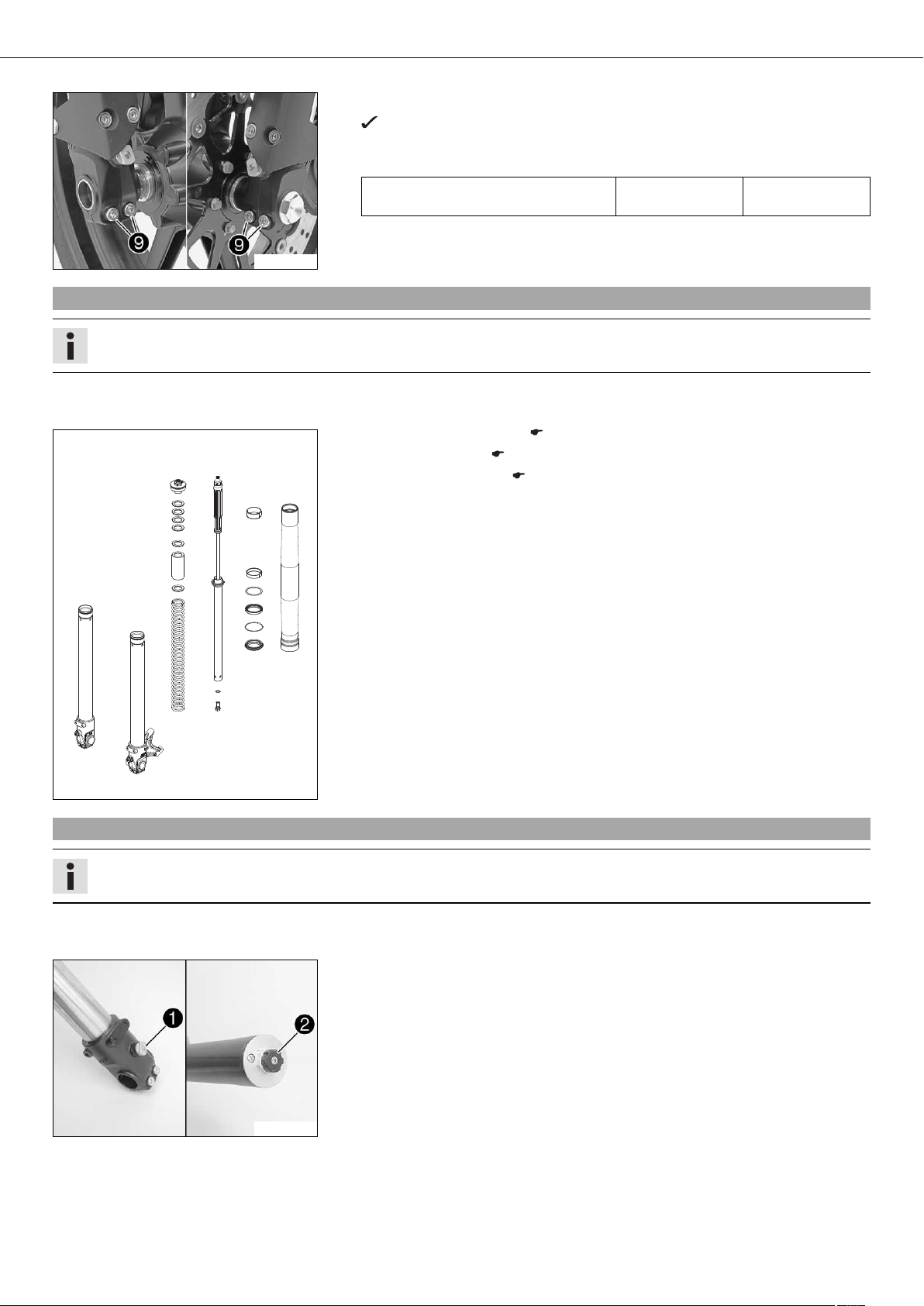
5.7Disassembling the fork legs
Info
These operations are the same on both fork legs.
200660-01
Condition
The fork legs have been removed.
– Establish and note the current state of the rebound damping and compression
damping .
– Completely open the adjusters of the rebound and compression damping.
01/FORK, TRIPLE CLAMP 17
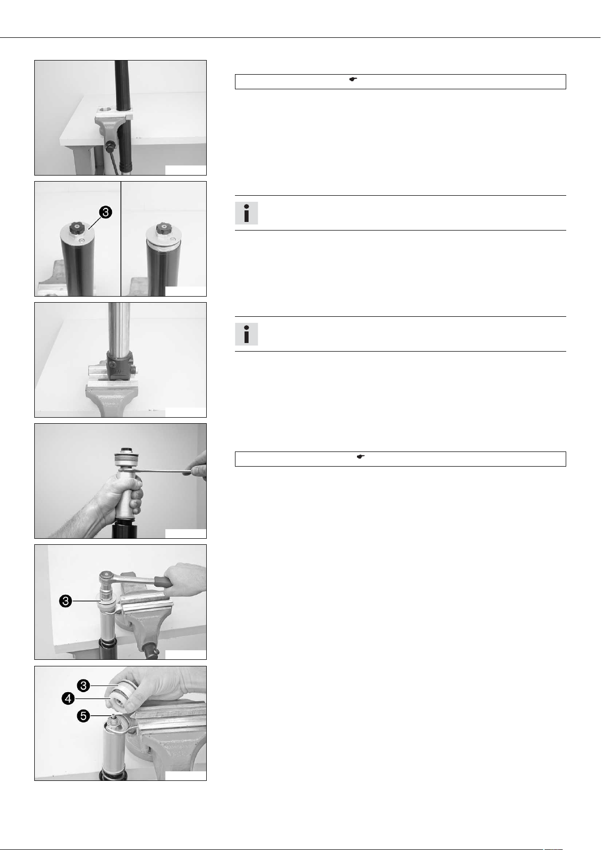
– Clamp the fork leg in the area of the lower triple clamp.
Clamping stand (T1403S) ( p. 257)
200643-10
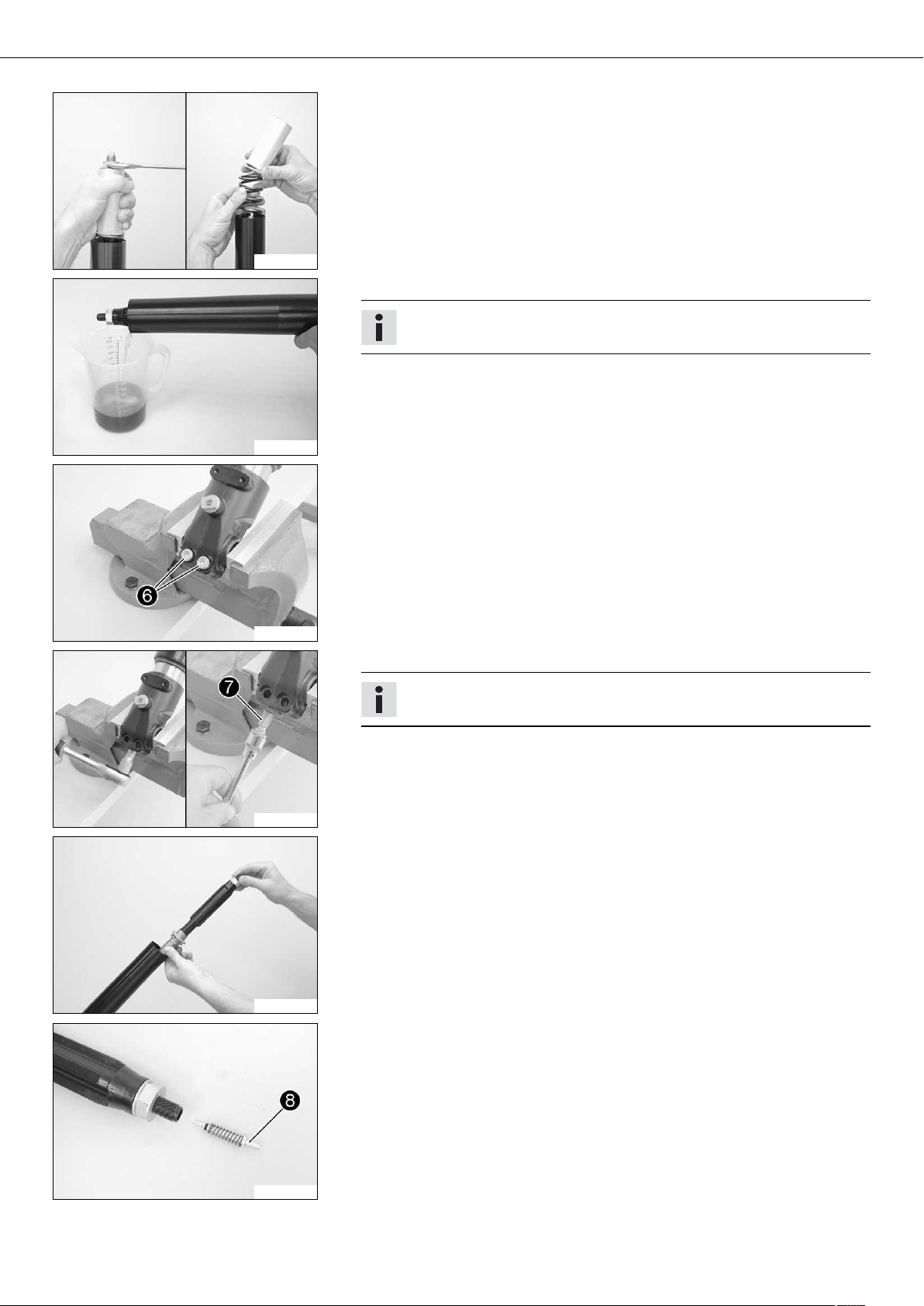
– Loosen the screw cover .
Info
The screw cover cannot be removed yet.
200644-12
– Release the fork leg and clamp it with the fork stub.
200661-01
200729-10
Info
Use soft jaws.
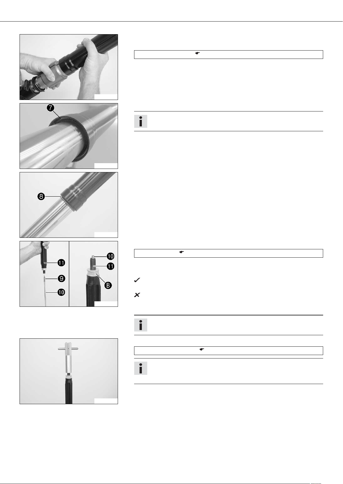
– Push the outer tube downward.
– Pull the tube downwards. Mount the special tool on the hexagon.
Open-end wrench (T14032) ( p. 257)
– Clamp the special tool in the vise. Loosen the screw cover .
200730-10
200731-10
– Remove screw cover with preload spacers .
– Remove adjusting tube .
01/FORK, TRIPLE CLAMP 18
– Pull the tube downwards. Remove the special tool.
– Remove the tube, washer and spring.
200732-10
– Drain the fork oil.
Info
Pull out and push in the piston rod a few times to empty the cartridge.
200650-01
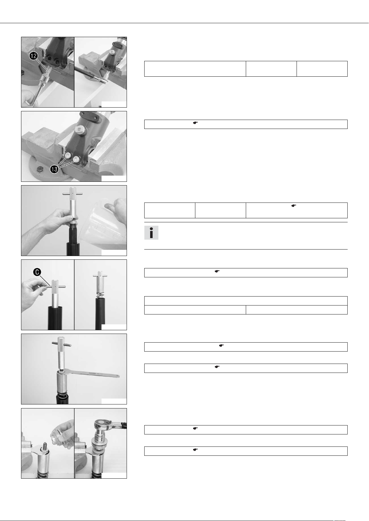
– Clamp the fork leg with the fork stub.
– Remove screws of the axle clamp.
200662-01
200667-10
200653-01
– Loosen screw of the cartridge and remove it with the sealing ring.
Info
Place a container underneath to catch any oil that may run out.
– Remove the cartridge.
– Remove valve of the rebound damping with the spring from the cartridge.
200654-12
01/FORK, TRIPLE CLAMP 19
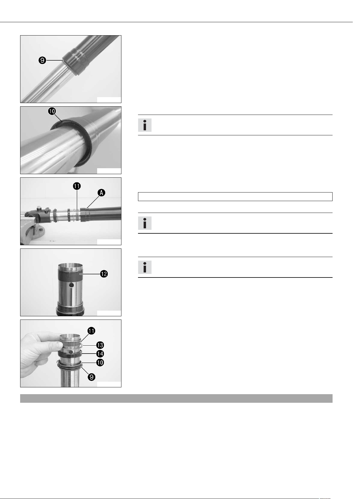
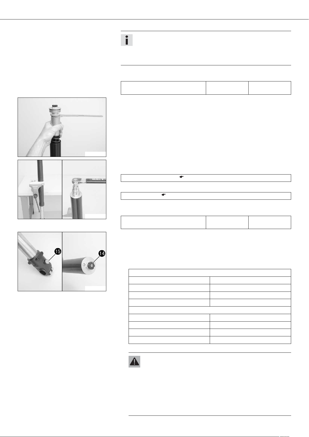
– Remove dust boot .
200655-12
– Remove lock ring .
Info
The lock ring has a beveled end where a screwdriver can be applied.
200656-12
– Heat up the outer tube in area of the lower sliding bushing.
Guideline
50 °C (122 °F)
200668-10
200658-12
– Pull the fork outer tube with a jerk from the inner tube.
Info
The lower sliding bushing must be pulled from its bearing seat.
– Remove the upper sliding bushing .
Info
Without using a tool, carefully pull the stack apart by hand.
– Take off the lower sliding bushing .
– Take off support ring .
– Take off seal ring .
– Take off lock ring .
– Take off dust boot .
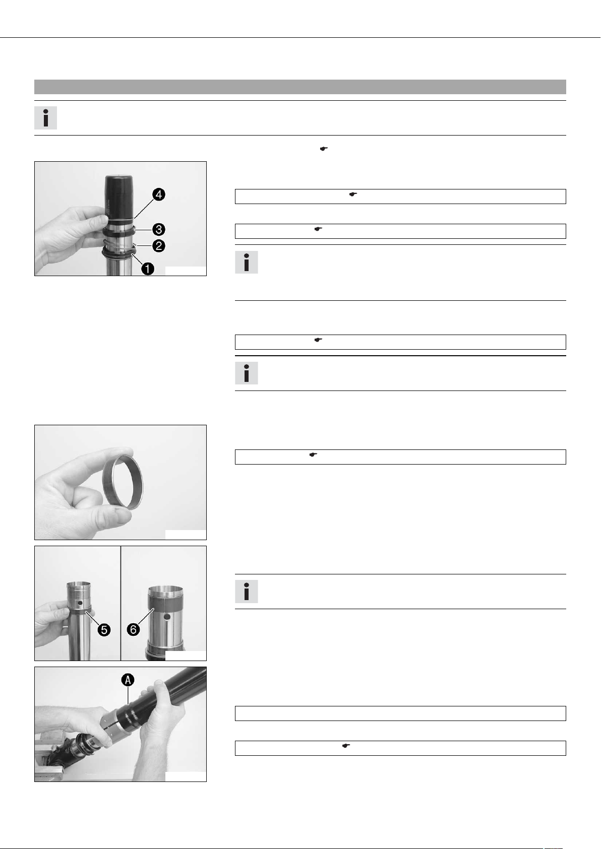
5.8Checking the fork legs
200659-12
Condition
The fork legs have been disassembled.
01/FORK, TRIPLE CLAMP 20
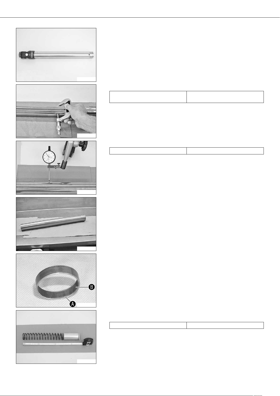
– Check the inner tube and the axle clamp for damage.
» If damage is found:
– Replace the inner tube.
200686-10
– Measure the external diameter of the inner tube in several places.
External diameter of inner tube 47.975… 48.005 mm (1.88878…
1.88996 in)
» If the measured value is less than the specified value:
– Replace the inner tube.
200684-10
– Measure the run-out of the inner tube.
Run-out of inner tube ≤ 0.20 mm (≤ 0.0079 in)
200685-10
200632-10
» If the measured value is greater than the specified value:
– Replace the inner tube.
– Check the outer tube for damage.
» If damage is found:
– Replace the outer tube.
– Check the surface of the sliding bushings.
» If the bronze-colored layer under sliding layer is visible:
– Replace the sliding bushings.
200665-10
201249-10
– Check the spring length.
Guideline
Spring length with preload spacer(s) 352 mm (13.86 in)
» If the measured value is greater than the specified value:
– Reduce the strength of the pretensioning bushes.
» If the measured value is less than the specified value:
– Increase the strength of the preload spacers.
01/FORK, TRIPLE CLAMP 21
5.9Assembling the fork legs (Duke)
Info
These operations are the same on both fork legs.
– Check the fork legs. ( p. 19)
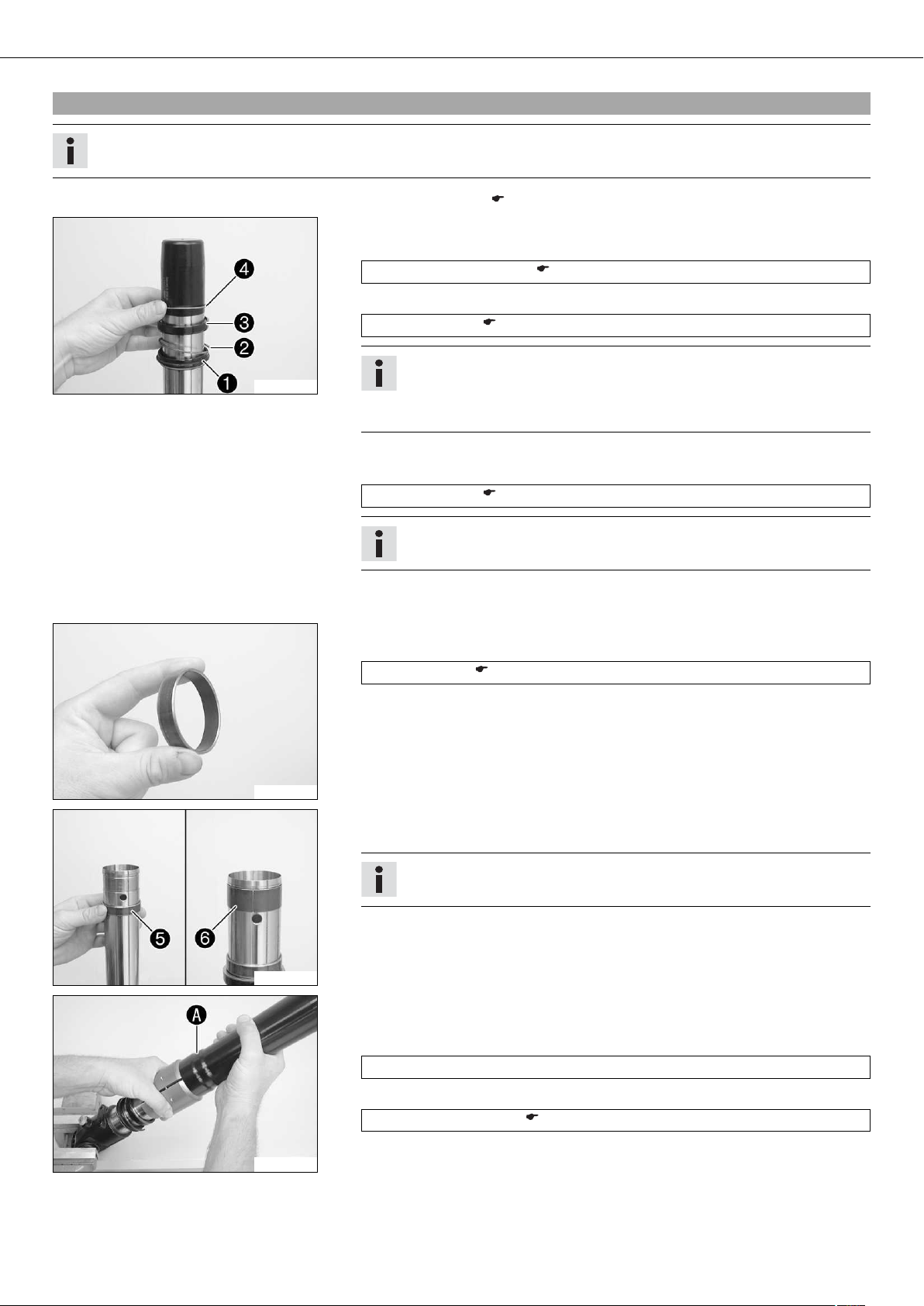
– Clamp the inner tube with the axle clamp.
– Mount the special tool.
Protecting sleeve (T1401) ( p. 256)
– Grease and push on dust boot .
Lubricant (T511) ( p. 244)
Info
200669-10
– Push on lock ring .
– Grease and push on seal ring .
Always replace the dust boot, seal ring, lock ring, and support ring.
Install the dust boot with the sealing lip and spring expander facing downward.
Lubricant (T511) ( p. 244)
200670-10
200671-10
Info
Sealing ring downward, open side upward.
– Push on support ring .
– Remove the special tool.
– Sand the edges of the sliding bushes with 600-grain sandpaper, then clean and
grease them.
Fork oil (SAE 5) ( p. 243)
– Push on the lower sliding bushing .
– Mount the upper sliding bushing .
Info
Without using a tool, carefully pull the stack apart by hand.
– Push on the outer tube.
– Heat up the outer tube in area of the lower sliding bushings.
Guideline
50 °C (122 °F)
200672-10
– Hold the lower sliding bushing with the longer side of the special tool.
Assembly tool (T1402S) ( p. 257)
– Press on the outer tube as far as it will go.
01/FORK, TRIPLE CLAMP 22
– Position the support ring.
– Hold the seal ring with the shorter side of the special tool.
Assembly tool (T1402S) ( p. 257)
– Press on the outer tube as far as it will go.
200673-10
– Mount lock ring .
Info
The lock ring must engage audibly.
200656-11
– Install dust boot .
200655-11
200674-10
200675-10
– Grease the O-ring of valve of the rebound damping.
Lubricant (T158) ( p. 244)
– Mount valve of the rebound damping with the spring on adjusting tube .
– Mount valve of the rebound damping from below in cartridge .
The adjusting tube protrudes 5 mm from the cartridge and can be pressed in
against the resistance of the spring.
The adjusting tube protrudes more than 7 mm from the cartridge and cannot
be pressed in against the resistance of the spring.
– Screw on fluid barrier as far as it will go.
Info
The fluid barrier must be tightened as much as possible. Do not use tools.
– Install the special tool on the cartridge.
Gripping tool (T14026S1) ( p. 256)
Info
The special tool must be used to prevent the adjusting tube being lifted and
thus to prevent oil from reaching the piston rod.
01/FORK, TRIPLE CLAMP 23
– Push the cartridge with the spring seat and preload spacer into the inner tube.
– Mount screw of the cartridge with the seal ring and tighten it.
Guideline
Cartridge screw M12x1 25 Nm
(18.4 lbf ft)
200683-10
– Grease and mount screws of the axle clamp but do not tighten.
Lubricant (T152) ( p. 245)
200682-10
– Clamp the fork vertically.
– Fill it with fork oil.
200677-10
201245-10
Fork oil per fork
leg
775 ml
(26.2 fl. oz.)
Fork oil (SAE 5) ( p. 243)
Info
Pull out and push in the piston rod completely a few times to remove air
from the cartridge.
– Remove pin of the special tool.
Gripping tool (T14026S1) ( p. 256)
– Pull out the piston rod. Mount the spring and tube. Mount the spring again.
Guideline
Spring rate
Medium (standard) 6.5 N/mm (37.1 lb/in)
– Pull the tube downwards. Mount the special tool on the hexagon.
Open-end wrench (T14032) ( p. 257)
– Remove the special tool.
Gripping tool (T14026S1) ( p. 256)
201246-10
201247-10
– Clamp the special tool in the vise.
– Grease the thread of the piston rod.
Lubricant (T159) ( p. 245)
– Grease the upper edge of the piston rod.
Lubricant (T158) ( p. 244)
– Screw the screw cover with the preload spacers on to the piston rod.
01/FORK, TRIPLE CLAMP 24
Info
The screw cover must be screwed to the stop before the piston rod starts
to turn. If the thread of the piston rod is stiff, it must be held to prevent
it from turning. If the screw cover is not screwed to the stop, the rebound
adjustment will not work correctly.
– Tighten the screw cover.
Guideline
Screw cover on piston rod M12x1 25 Nm
(18.4 lbf ft)
– Release the special tool. Pull the tube downward and take off the special tool.
201248-10
– Push the outer tube upward.
– Clamp the fork in the area of the lower triple clamp.
200681-10
200660-11
Clamping stand (T1403S) ( p. 257)
– Grease the O-ring of the screw cover.
Lubricant (T511) ( p. 244)
– Screw on and tighten the screw cover.
Guideline
Screw cover on outer tube M51x1.5 50 Nm
(36.9 lbf ft)
Alternative 1
– Turn the adjusting screw of rebound damping and the adjusting screw of
compression damping clockwise as far as possible.
– Turn back counterclockwise by the number of clicks corresponding to the fork
leg type.
Guideline
Rebound damping
Comfort 20 clicks
Standard 15 clicks
Sport 10 clicks
Full payload 10 clicks
Compression damping
Comfort 20 clicks
Standard 15 clicks
Sport 10 clicks
Full payload 10 clicks
Alternative 2
Warning
Danger of accidents Modifications to the suspension settings can seri-
ously alter the vehicle's ride behavior.
– Extreme modifications to the adjustment of the spring elements can
cause a serious deterioration in the handling characteristics and
overload some components.
– Only make adjustments within the recommended range.
– After making adjustments, ride slowly at first to get the feel of the
new ride behavior.
01/FORK, TRIPLE CLAMP 25
– Turn the adjusting screws to the position they were in before dismantling.
5.10Assembling the fork legs (Duke R)
Info
These operations are the same on both fork legs.
– Check the fork legs. ( p. 19)
– Clamp the inner tube with the axle clamp.
– Mount the special tool.
Protecting sleeve (T1401) ( p. 256)
– Grease and push on dust boot .
Lubricant (T511) ( p. 244)
Info
200669-10
– Push on lock ring .
– Grease and push on seal ring .
Always replace the dust boot, seal ring, lock ring, and support ring.
Install the dust boot with the sealing lip and spring expander facing downward.
200670-10
Lubricant (T511) ( p. 244)
Info
Sealing ring downward, open side upward.
– Push on support ring .
– Remove the special tool.
– Sand the edges of the sliding bushes with 600-grain sandpaper, then clean and
grease them.
Fork oil (SAE 5) ( p. 243)
– Push on the lower sliding bushing .
– Mount the upper sliding bushing .
Info
Without using a tool, carefully pull the stack apart by hand.
200671-10
200672-10
– Push on the outer tube.
– Heat up the outer tube in area of the lower sliding bushings.
Guideline
50 °C (122 °F)
– Hold the lower sliding bushing with the longer side of the special tool.
Assembly tool (T1402S) ( p. 257)
– Press on the outer tube as far as it will go.

01/FORK, TRIPLE CLAMP 26
– Position the support ring.
– Hold the seal ring with the shorter side of the special tool.
Assembly tool (T1402S) ( p. 257)
– Press on the outer tube as far as it will go.
200673-10
– Mount lock ring .
Info
The lock ring must engage audibly.
200656-11
– Install dust boot .
200655-11
200674-10
200675-10
– Grease the O-ring of valve of the rebound damping.
Lubricant (T158) ( p. 244)
– Mount valve of the rebound damping with the spring on adjusting tube .
– Mount valve of the rebound damping from below in cartridge .
The adjusting tube protrudes 5 mm from the cartridge and can be pressed in
against the resistance of the spring.
The adjusting tube protrudes more than 7 mm from the cartridge and cannot
be pressed in against the resistance of the spring.
– Screw on fluid barrier as far as it will go.
Info
The fluid barrier must be tightened as much as possible. Do not use tools.
– Install the special tool on the cartridge.
Gripping tool (T14026S1) ( p. 256)
Info
The special tool must be used to prevent the adjusting tube being lifted and
thus to prevent oil from reaching the piston rod.

01/FORK, TRIPLE CLAMP 27
– Push the cartridge with the spring seat and preload spacer into the inner tube.
– Mount screw of the cartridge with the seal ring and tighten it.
Guideline
Cartridge screw M12x1 25 Nm
(18.4 lbf ft)
200683-10
– Grease and mount screws of the axle clamp but do not tighten.
Lubricant (T152) ( p. 245)
200682-10
– Clamp the fork vertically.
– Fill it with fork oil.
200677-10
201245-10
Fork oil per fork
leg
760 ml
(25.7 fl. oz.)
Fork oil (SAE 5) ( p. 243)
Info
Pull out and push in the piston rod completely a few times to remove air
from the cartridge.
– Remove pin of the special tool.
Gripping tool (T14026S1) ( p. 256)
– Pull out the piston rod. Mount the spring and tube. Mount the spring again.
Guideline
Spring rate
Medium (standard) 7.5 N/mm (42.8 lb/in)
– Pull the tube downwards. Mount the special tool on the hexagon.
Open-end wrench (T14032) ( p. 257)
– Remove the special tool.
Gripping tool (T14026S1) ( p. 256)
201246-10
201247-10
– Clamp the special tool in the vise.
– Grease the thread of the piston rod.
Lubricant (T159) ( p. 245)
– Grease the upper edge of the piston rod.
Lubricant (T158) ( p. 244)
– Screw the screw cover with the preload spacers on to the piston rod.

01/FORK, TRIPLE CLAMP 28
Info
The screw cover must be screwed to the stop before the piston rod starts
to turn. If the thread of the piston rod is stiff, it must be held to prevent
it from turning. If the screw cover is not screwed to the stop, the rebound
adjustment will not work correctly.
– Tighten the screw cover.
Guideline
Screw cover on piston rod M12x1 25 Nm
(18.4 lbf ft)
– Release the special tool. Pull the tube downward and take off the special tool.
201248-10
– Push the outer tube upward.
– Clamp the fork in the area of the lower triple clamp.
200681-10
200660-11
Clamping stand (T1403S) ( p. 257)
– Grease the O-ring of the screw cover.
Lubricant (T511) ( p. 244)
– Screw on and tighten the screw cover.
Guideline
Screw cover on outer tube M51x1.5 50 Nm
(36.9 lbf ft)
Alternative 1
– Turn the adjusting screw of rebound damping and the adjusting screw of
compression damping clockwise as far as possible.
– Turn back counterclockwise by the number of clicks corresponding to the fork
leg type.
Guideline
Rebound damping
Comfort 25 clicks
Standard 20 clicks
Sport 15 clicks
Full payload 15 clicks
Compression damping
Comfort 20 clicks
Standard 15 clicks
Sport 10 clicks
Full payload 10 clicks
Alternative 2
Warning
Danger of accidents Modifications to the suspension settings can seri-
ously alter the vehicle's ride behavior.
– Extreme modifications to the adjustment of the spring elements can
cause a serious deterioration in the handling characteristics and
overload some components.
– Only make adjustments within the recommended range.
– After making adjustments, ride slowly at first to get the feel of the
new ride behavior.
 Loading...