

Page 1
KROHNE 06/20057.30935.32.00
©
GR
DIN A4: 7.10028.31.00
Service Handbook
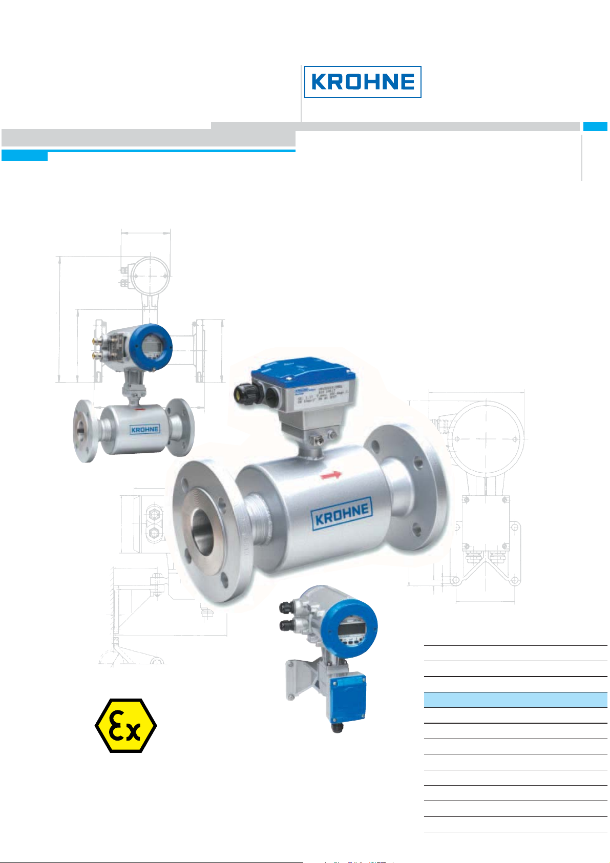
Universal 3-Beam
ultrasonic flowmeter
UFM 3030 K/…EEx compact ultrasonic flowmeter
UFC 030 F/…EEx ultrasonic flow converter
UFS 3000 F/…EEx ultrasonic flow sensor
Subject to change without notice.
Electromagnetic flowmeters
Variable area flowmeters
Mass flowmeters
Ultrasonic flowmeters
Vortex flowmeters
Flow controllers
Level measuring instruments
Pressure and temperature
Heat metering
Communications technology
Switches, counters, displays and recorders
Engineering systems & solutions
Page 2
General advice on safety
• Do not instal l, operat e or maint ain this flow m eter wit h out reading, under standing and f ol lowing
the factor y-supplied in str uctions , other wi se inju ry or damage may r esu lt.
• Read these instructions carefully before starting installation and save them for future reference.
• Obs erve all war nings and instr u ctions marked on the pr oduct.
• Use only m a ins supply wi th protec tive ea rthi ng c onnected.
• Do not use the product with removed covers under wet conditions.
• Consider handling and lifting instructions to avoid da ma ge.
• Install the product securely and stable.
• Install and connect cabling proper to exclude damage or harmful situations.
• If the product does not operate normally, refer to the service instructions or refer to qualified
KROH N E servi ce en gi neers.
• There are no op erator-servi c eab le parts insi de the product.
The following symbols may appear in this manual or on the product
ATTENTIO N: r ef er to oper ating and installation instructi ons !
DANGER: ris k of elec tric shock!
PROTECTIVE conductor terminal!
These terms may appear in this manua l or on the product:
WARNING statement: identify conditi ons or practice that could result in injury or
loss of life.
CAUTI ON statemen t : identify c o nditions or practice that could result in dam a ge t o
th e pr oduct or othe r pr oper ty.
2 UFM 3030
Page 3

Disclaimer
• This do c ument contains impor t ant information on the product. KROHNE attempts t o be as
accurate and up-to-date as possible but assumes no responsibility for errors or omissions. Nor
does KROHNE make any com m it m ent to upda t e the inf ormation contained herein. T hi s m anual
an d all ot her documents are subject to change w it h out prior notic e.
• KROHNE will not b e lia ble for any damage of any kind by using its product , in cl u ding, but not
limited to direct, indirect, incidental, punitive and consequential damages.
• Th is disc laimer does not app ly i n ca se KROHNE ha s ac ted on purp os e o r with gr os s n egligence.
In the event any applica ble l aw does n ot allow such limita tions on implied wa rr a nt i es or the
exclusion of limitation of certain damages, you may, if such law applies to you, not be subject to
some or all of th e above di sclaimer, exclus ions or limit ations.
• Any product purchased from KROHNE is warranted in accordance with the relevant product
docum entation and our Terms and Condition s of Sal e.
• KROH N E reser ves the r ight to al ter the co ntent of its d o cuments, incl udi ng this di sclaimer in any
way, at any time, for any reason, without prior notification, and will not be liable in any way for
possib le consequences of such changes .
Product liability and warranty
• Responsi bility f or suitabilit y and int end ed us e of t his ultrasonic f l ow meter rests solel y with the
user. Improper inst allation and oper at i on of the flow meter (syst em ) ma y l ead to los s of warr a nt y.
• In addition, the Term s an d Conditions of Sale ar e applic a ble and are the basi s for the purchase
contract.
• If fl ow meter s need to be returned to KROHNE , pleas e note the informa tion given on the la st
pages of t he installati o n and oper at i ng instructi ons. KROHNE regret s that t hey cann ot repair or
check flow meter(s) unless accompanied by the completed form (see last pages of the
installation and operating instructions).
Items included with order
• UFM 3030 ult ras onic flow meter , com pr is ing of a flow sensor, UFS 3 000 and a sig nal converter,
UFC 030 either built tog ether as a compact system or supplied as two separat e pieces, in the
size as indicated on the packaging box
• Signal cable (only in case of a separate system)
• Special t ool for opening the converter housi ng
Documentation supplied
• Condensed installation and operat i ng manual
• For Ex- units: installation and opera ting instru ctions for use i n hazardous areas
• Instruction card : o v er vi ew of the co nfiguration menu and display ma rkers
• Product information CD
• Appro v al d oc uments, unless r epr oduced in the installatio n and oper a ting instructions
• Cert ific ate of sy st em calibration dat a
UFM 3030 3
Page 4

This instrument is develo ped a nd manufactur ed by:
KROHNE Altometer
Ker kep la at 12
3313 LC Dordr echt
The N et h erla n ds
For information, mai ntenance or servi c e pleas e co ntact your nearest local KROHNE repr esentative.
Notes on the ser vice handbook
This service handbook is divided into four parts for easy use. All ultrasonic flow meters are factoryset to your or der sp ecificati ons . Th erefore, no furt h er adjustments ar e necess ary prior to init ia l startup. Condens ed installation and operating instr uctions are available for installatio n and init i al start-u p.
Part A Chapter s 1, 2 and 3; System installati o n and star t - up. Install ati o n, con nec ting and
powering the flow meter.
Part B Chapter s 4 and 5; The sign al conv er ter. Operato r cont rol and function ing of the
signal converter.
Part C Chapters 6 and 7; Functional checks and service. Servicing the flow meter.
Part D Chapters 8, 9 and 10; Technical data. dimensi ons, block dia gram and ultrasonic
measuri ng principl e.
4 UFM 3030
Page 5

Table of contents
1
Introduction 6
1.1 Cautions 6
1.2 Unpacking and inspection 6
1.3 System description 6
1.4 Av ailable ver si ons 7
1.5 CE A pprovals 7
2 Mech a n ic a l in sta llatio n 8
2.1 Handli n g t he flowmeter 8
2.2 Installation location and position 8
2.3 Special installation requirem ents 9
2.4 Pipe fl anges 10
2.5 Pipes with cathodic pr otection 11
3 Connecting the signal converter 12
3.1 Safety instr ucti o ns 12
3.2 Converter terminal box 12
3.3 Power supply connection 12
3.4 Co n nec tion of s ens or cables ( UFM 303 0 F only) 13
3.5 Electrical connection of the sig nal i np ut s an d outputs 14
3.6 Connect i on diagram exam ples 16
4 Start-up 17
5 Operating the signal converter 18
5.1 Fron t panel a nd oper at ing keys 18
5.2 Menu structure and func tion of operati ng keys 19
6 Description of functions 28
6.1 Menu structure 28
7 Functional checks 40
7.1 Test functions of the signal converter Function 2.1 to 2.5 40
7.2 Measuri ng zero flow v alu e 41
8 Servi ce an d Repair 42
8.1 Replacement of elect r onic u nit of sign al convert er 42
8.2 Replacement of ultr as onic flow sensor in separ ate systems 42
8.3 Change of po wer s upp ly fu s e 43
8.4 Cleaning 44
8.5 Turning the display circuit board 44
8.6 Turn ing the signal c onv er ter hous ing 44
9 Returning the flow meter for service or repair 45
10 Dimensions 46
11 Block diagram 46
12 Ultrasonic measurement principle 47
12.1 Transit time differential method 47
12.2 Three beam ultr asonic measurement 47
UFM 3030 5
Page 6
Part A System Installati on and Start-up
1 Introduction
1.1 Cautions
Only for flow meters supplied with a voltage over 5 0 VAC.
Refer all maintenance or servi c e to tra i ned KROHNE service eng ineers.
Mains power s hall be disconnected from the product before performing any
maintenance.
This product is prepared for and can only function with the rated AC mains voltage
as indicated on the nameplate.
This product is a Class 1 device (earthed) and requ ir es a c orrect connecti on to
prot ective earth. The protective ear th conductor of the m ain power s h all be properl y
connected to the marked protective earth terminal to ensure safety from electric
shock for the operator and its environment. For detail refer to this s er vi ce handbook.
1.2 Unpacking and inspection
• This pro du ct has been thorou ghly inspected and t ested before shi pment and is ready for
operation.
• After carefully unpacking, inspect for shipping damage before attempting to operate. If any
indi c ation of mechanic al damage is found contact immediately the r esp on sible trans por t s ervi c e
and your local KROHNE representative.
• A simpl e oper at i ng check of the electr oni c s after unpacki n g and bef ore permanent installation is
advisable to ascertain whether it has suffered damage during shipment. Confirm for the correct
mains voltage printed on the namepla te. I f it diff ers f rom th e ordered produc t pleas e co n tact y our
local KROHNE representative.
• Afte r connectin g to t he m ain s , ch eck i f th ere is any i n dica tion on the dis p lay an d if the b acklight
of the display is lighted. If not, contact your local KROHNE representative for advice.
1.3 System description
The UFM 3030 ultra sonic flow meter is a precis ion instr ument designed for li n ear, bi/directional flow
measur ement of liquids. Flow measurem ent val ues c a n be outp ut vi a t he standard anal og and- or
pulse/f requency out puts. Via a user friendly operat or int er f ac e (HMI) the unit can be set up for a
wide range of applications. Next to actual volumetric flow measurement the unit can be configured
to perform flow totalization (pl us, mi nus and sum ). Also measurement and output of t he liqu id so nic
velocity can be configu r ed. Op tionally the unit c an b e set to perfo rm one of the followi n g additional
functions:
• Ca lc ulate a nd ou tput corrected stan dar d volumetri c or mas s f low usin g the extern a l pres sure
and temperature inputs
• Batch function
• Heat function, combining T1, T2 and volume
6 UFM 3030
Page 7
1.4 Available versions
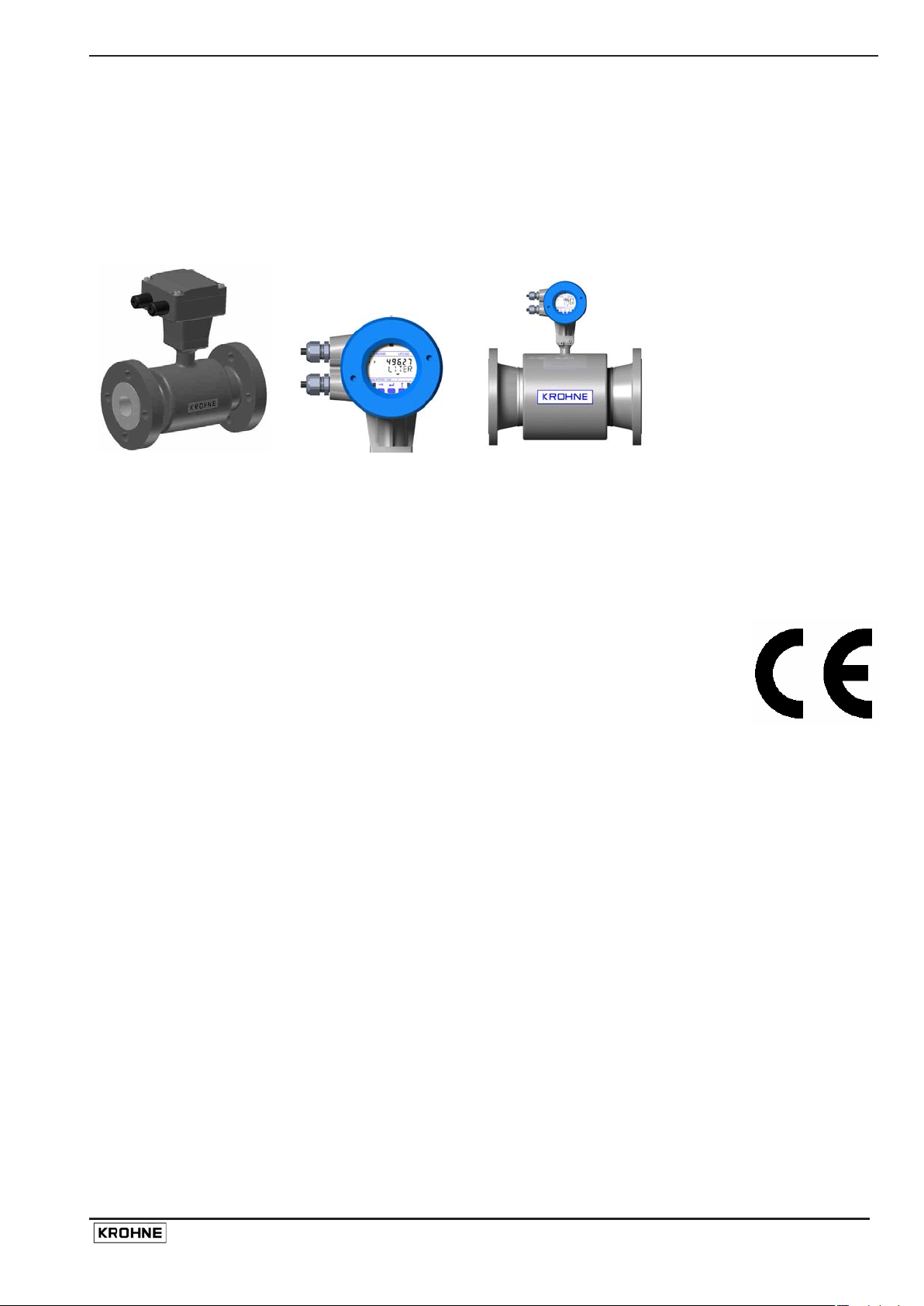
The UFM 3030 consists of a flow sensor ( UFS 30 00) and a signal conv ert er ( UFC 030), which can
be built i nt o a comp act flo w m eter, UF M 30 30 K or a separate fl o w m eter, UF M 3030 F.
Both flow sensor and signal converter are available with an approval for use in hazardous areas.
Special c od es and regulati ons apply i n thes e ar eas and are refer r ed to in the instructions for
hazardous area versions, supplied as a separate manual.
UFS 3000 UFC 030 UFM 3030 K
1.5 CE Approvals
EMC, Electr oma gn e tic Compatibility Directive
The produ ct complies wit h the requi r em ent s of t he harm o nis ed standards u nd er
the EMC directive 89/336/EEC.
Low Voltage Directive
The produ ct compl ies with the requir em ent s of t he Lo w Voltage Directi v e
73/23/EEC and is designed in accordance with EN IEC 61010-1 first and second
edit ion . (s afety req uirements for elec tr ica l equipment for measurement , control
and laboratory use part 1)
Lo cal saf e ty regul a t io ns shall b e obs erved in c ombination with t he measu res
special to this product to avoid dangerous situations.
Pressure Equipment Directive
The KROHNE organisation com plies with the requirements of Modu le H of the
Pr ess u re Equipment Di rective 97/23 /EC ( full quali t y assurance).
Please refer to the CE declaration for more detailed information.
UFM 3030 7
Page 8
2 Mechanical installation
2.1 Handling the flowmeter
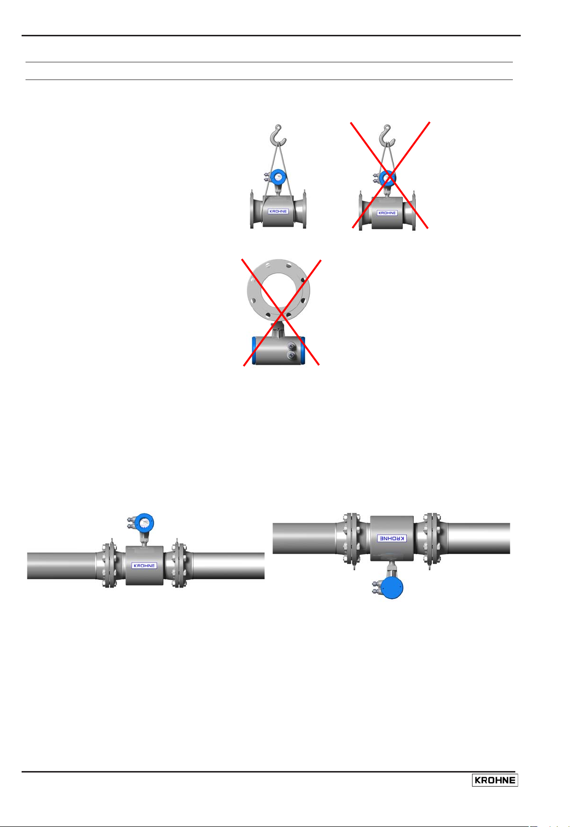
Important: Do not lift the compact
flowmeter by the signal converter
housing or the terminal box. Check the
weight of the flowmeter as indicated on
the type plate before handling the unit.
When handli ng the flowm eter avo i d hard
blows, jolts or impacts.
Do not plac e the fl owmeter on the sign al
conver ter housing.
2.2 Installation location and position
The UFM 3030 flow meter can be instal l ed in hori zo ntal, sli ghtly ascendin g or vertical pipelines.
If insta lled i n a horizontal or s lightly asc e ndin g pip elin e, a lways i ns tall the c onv ert er or terminal
box in vertical positi o n opposite th e flow sens or ei ther with the conver ter up or down, but never in
horizontal position.
8 UFM 3030
Page 9
If requi red the po sit io n of the signal con verter ca n be m odifi ed b y turning th e dis p lay circ u it b oard
thr ough 90° or 18 0° t o achi eve a hor izontal posit ion of the display. In additi on the signal converter
housing may be turned through 90° opposite the flow sensor.
For an exact description of this procedure, refer to chapter 8.6.
The measuring tube must be completely filled at all times for proper flow measurement, as the
sensor s bec ome non-wetted, a los s of si gnal message will be disp layed. There is no damage
when thi s occ u rs.
Flow dir ect ion. The UFM 3030 is a bi-dir ec tional flo w meter . Note the indicati ng arrow for the
positive direction on the flow meter.
It is recommended to protec t t h e signal converter fr om direct sunlight to prol ong the life. Alth ough
no direct damage will occur, installation of a sunshield is advised.
Do not expose the signal converter to excessive vibration. To protect the flow meter from
excessi v e vibrati on su pport t he pip eline on either si de of th e flow meter.
Make sure there is sufficient room next to the pipe flanges to fit the bolts and nuts.
To achieve t he spec ified accur acy of the flow meter , a straig ht inlet s ection of 10 × DN (D N =
met er size) an d an outlet section of 5 × DN should be applied.
Norm all y zero s ett i ng is not necessary , but if r equired the zero p oin t can b e checked and the
meter can be re-zeroed under stationary flow conditions (see Function 1.01.03 of the converter
menu). To f orc e zero flow , a shut - off valve should be p ro v ided u pstr eam a nd/ or do wnstream of
the flow sens or.
Mixi ng different fluid products. Install the fl ow meter upstream of mix ing point or at minim um
dist an c e of 30× D N (DN = meter size) do wnstream of the mixing point, otherwise the flow
meas urem ent may be unstable.
Ambient temperature all flow meters: -40 to +65°C/ -40 to +149°F
Product temperature compact flow meter: -25 to +140°C/ -13 F to +284°F
Prod u ct tempera ture separate flow meter: -25 to +1 8 0 °C/ -13 to +356°F
Special v er s ions are availa ble for higher proces s temperatur es.
In case of a pipel ine running alo ng a wall: pl eas e obs er v e a minim um distance between pipe
centreline and the wall of at least 0.5 m (1.6 ft).
2.3 Speci al installation requirem ents
To avoi d meas ur ing er rors and malfunctioning of the flow meter due to gas or air inclusions or an
empt y pipe, please observe t he following precau t io ns:
UFM 3030 9
Page 10
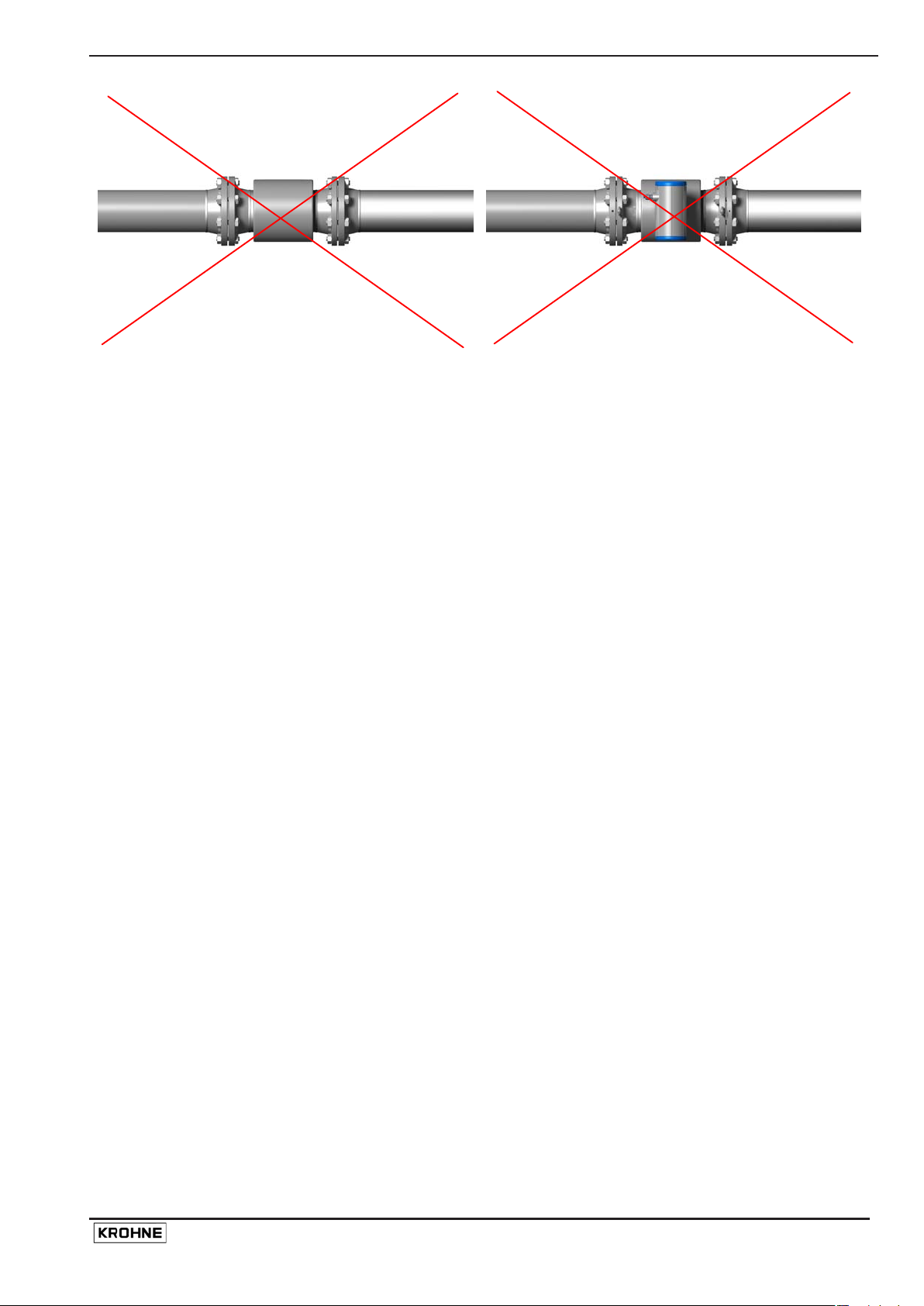
Sinc e gas will collect at the highest point of a pipe, in s tallati on of the flow meter at that locati o n
should be avoided at all times. Also installation in a down going pipe should be avoided since a
compl et ely fi lled pipe may not be guaranteed due to casca di ng aff ects. Additionally flow profile
distortion is possi ble.
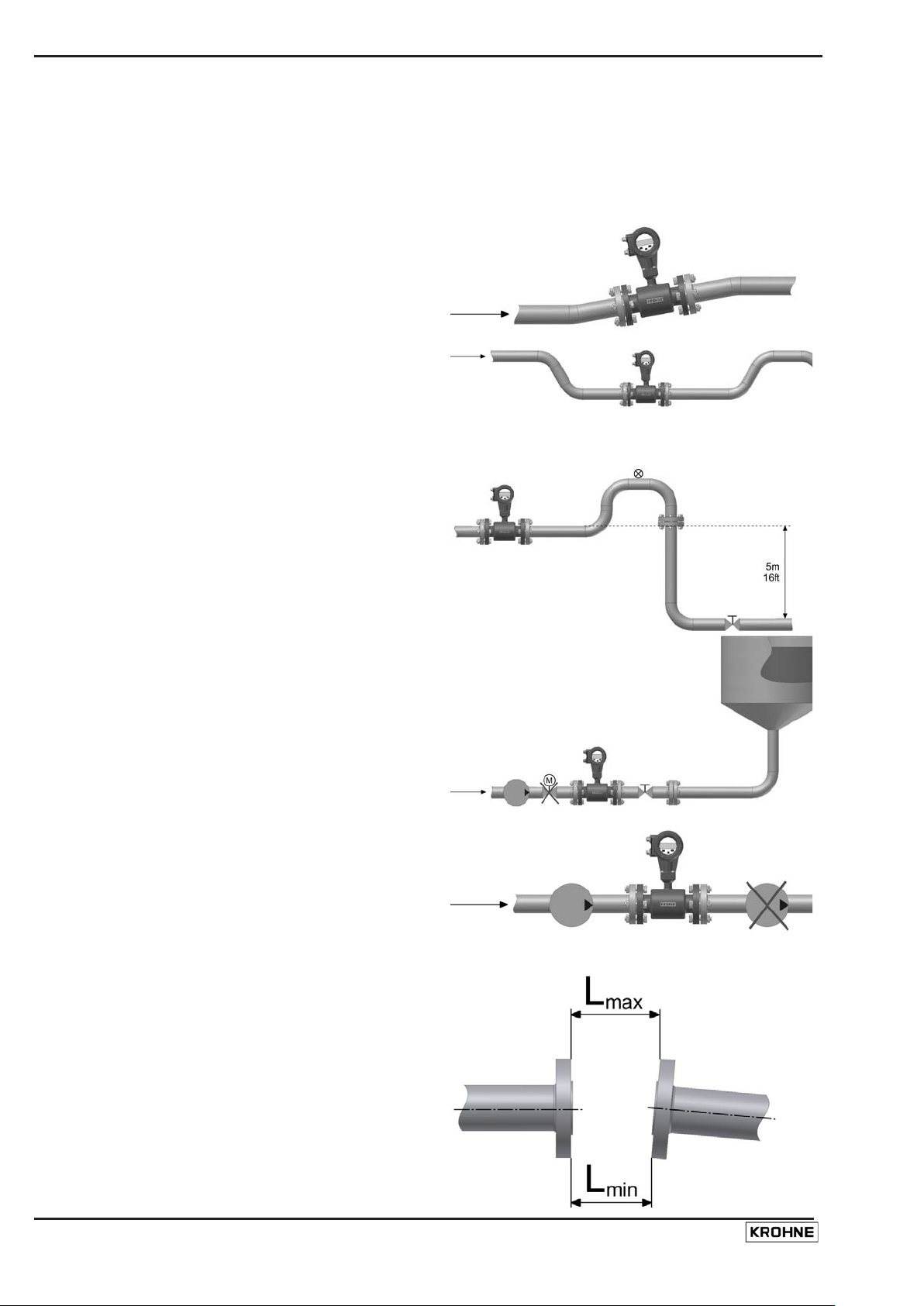
Long h orizontal pip es: ins tall in slightly ascending
pipe section. If not possi ble, ensur e adequate
velocity to prevent air, gas or vapour from
collecting in upper part of flow tube As a partial ly
filled meter will report higher than actual flow
rat es, or n ot meas ure (as transduc er pair s becom e
non-wetted).
Open feed or dis c h arge: Install m eter in a lower ed
section of the pipe to ensur e a full pipe condition
thro ug h th e meter .
Down goin g pipel ine over 5 m (16 ft) lengt h: install
air vent downstr eam of th e flow meter. To prevent
vacuum . While thi s wil l n ot harm t he m eter, it may
cause gas es to com e out of s olution (cavit ate) and
int erfere with proper m easurements.
Always install control valves downstream of flow
meter in order to avoid cavitation or distortion of
flow profile.
Never i nstall flow meter on a pump suct i on side in
order to avoid cavitation or flas hing in the flow
meter.
2.4 Pipe flanges
Refer to dimensional dra wings for flange s pacing
and in addition allow for thickness of gaskets.
Insta ll flow meter in line with pipe axis. Pip e fl an ge
faces must be parall el to each other, max.
Per missible deviation: Lmax - Lmi n ≤ 0.5 mm
(0.02").
10 UFM 3030
Page 11
2.5 Pip es with cathodic protection
Pipes with electric corrosion protection are generall y insulated inside and outside so that t he fluid
has no conductive connection to ground. The flow meter must be insulated from the pipe. Note
the foll owing when in stallin g th e flo w m eter:
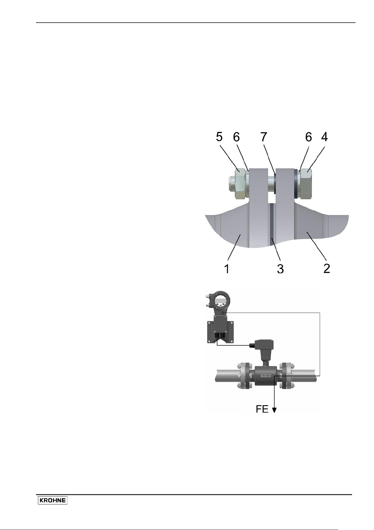
The pipe fl a nges must be connected to each other usin g a copper cable (L), but must not be
connected to the flow meter.
The bolts for the flange connections and the gaskets must be insulated. Use sleeves and washers
that are m ad e of ins ula ting material (these must be provided by customer).
1. Flange of flow sensor
2. Gas ke t
3. Pipe flange
4. Bol t
5. Nut
6. Washer
7. Insula t ing sle e ve
Follow grounding instructions.
Use ≥ 4 mm2 (≥ AWG 10 ca ble).
No te: No earthing c ables are sup plied b y
KROHNE.
UFM 3030 11
Page 12

3 Connecting the signal converter
3.1 Safety instructions
This product is designed for use in accordance with EN IEC 61010-1 for Installation Category 2
and Pollut i on Degr ee 2. Haza r dous voltag es are pr esent within thi s pro du ct during normal
operation. The product is designed for Pr otection Class I and should never be operated without
prot ective earthi ng. T he pr odu ct sha ll al s o never b e oper ated with covers rem ov ed unl ess
equivalent prot ecti on of the operator and its environment fr om accidental contact with hazar dous
inter n al voltages is provided. Always fol l ow basic and local safet y pr ecau t i ons when using thi s
product t o r educ e ri s k of injury from electrical shock , spr ead of fir e or other dangerou s sit uat io ns.
3.2 Converter terminal box
• The converter termi nal box is accessible after removi n g t he rear (blind) cover of the
el ect ro n ics sec tion using t he s pecial wr enc h s upplied with th e flow meter.
• Do not damage the screw thread and the gasket, never allow dirt to accumulate, and make
sure tha t the sc rew t hr ead i s w ell grea sed, using Tef lo n gr e ase a t all t i mes. A damaged
gaske t must be replaced imme d iately!
• Do not cross or loop the cables in the terminal box of the signal converter. Use separate cable
entries for power supply and signal cables.
• Special regulations apply to in stallation in hazardous areas (see installation instruction s for
hazardous areas).
3.3 Power supp ly connection
In case of con nection to the mains supply voltage:
Environmenta l co nditions
• The UFM3030 is desi gned to operate safe under the follo wi ng c onditi ons :
• Suita ble for indoor and outdoor use, the instrument is usable up to protecti on cat egory IP67
(IEC 60529)
• Use up to an altitu d e of 2000 m ab ov e see level
• Suita ble for an operati on ambient tempera ture range -40°C to +65° C
• Suitable for an storage temperature range -40°C to + 80°C
• Suitable for use in atmo s pheres wit h a relative humidity up to 80%
• Over voltages up to category II on the mai n sup ply voltage ( IEC 603 64- 4-4 43 )
• Connected to protective earth conductor ( Protection Class I)
• Rated pollution degr ee 2
• This in s trument is intend ed f or permanent connection to the mains. It is requir ed
(f or example for servic e) t o mount a n external switch or circuit br eaker near the
product for disconnection from the mains. It must be easily reachable by the
operator and marked as the dis c onnecting dev ic e f or this product.
The swi tch or circuit break er ha s to be suitable for the ap plic ation and shall als o
be in accor dance with to loc al (safety) requirements and of the building
installa t ion . (IEC 60947 -1 /-3 ).
• The pro tec tive conducto r cl am p t erminal size M5, pres s- fitted in the t erminal
compart ment (near the ma in c onnection termin als), shall alwa ys t o be c onnected
to the protective ear th conductor of the mai ns supply. Con ducto rs up to 4 mm²
(11 AWG) b e connect ed to this termin al. The diameter of t he cond uct ors of the
mains supply, in c ludi ng the protective earth c o nduct or s h all be i n accor danc e
wit h the general and local requir ements.
12 UFM 3030
Page 13
• It is not allowed to use the protective conductor terminal for any other connection
than the pro tectiv e ea rth co nduct o r.
• IP 67 i s only warranted when using suitable cabling with the cable glands and
covers mounted as specified.
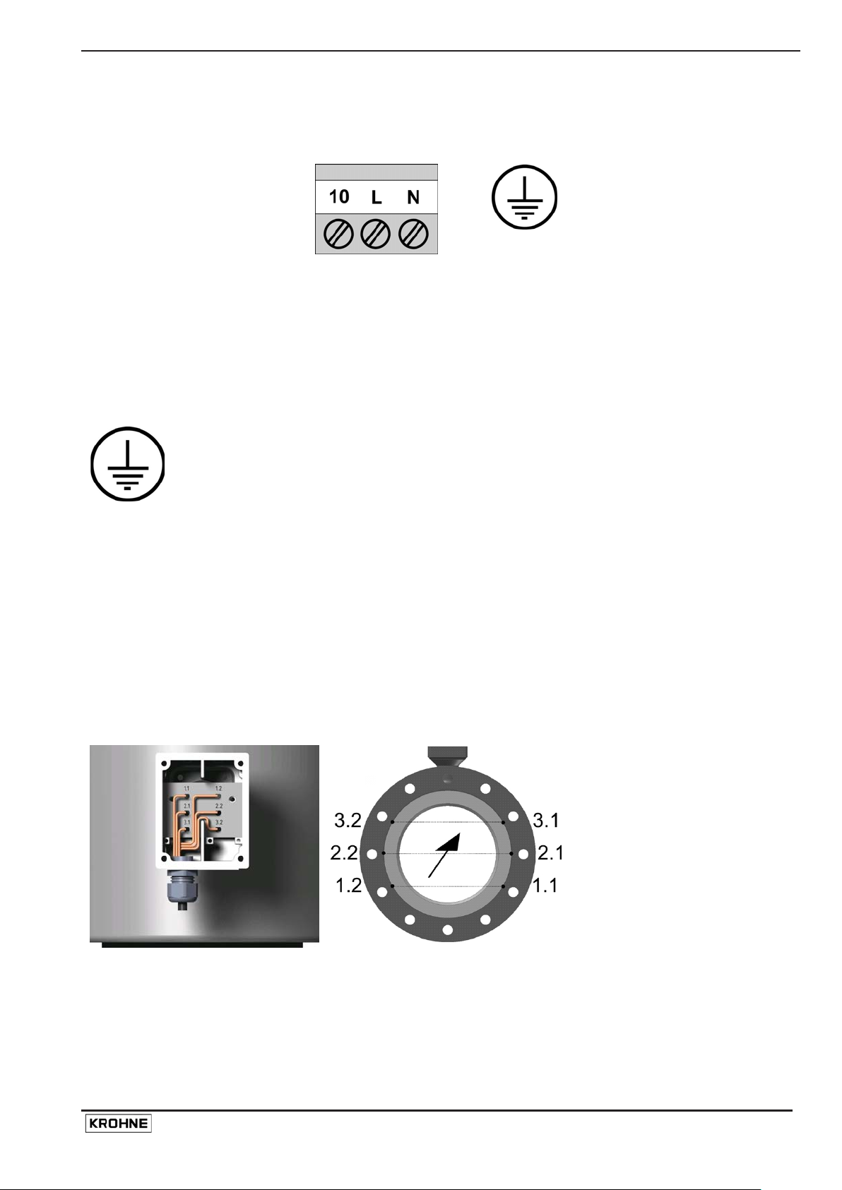
The power supply terminals
has thre e conne c tions
Th ere is a sep ar ate earthing
that must be connected:
:
Terminal Function Specification
10 Reserved G round connection Not for pro tective earthing
L / L1 Live power sup ply Mains vol t age AC supply:
100 V AC < U < 240 V AC: -15%, +10%
SELV AC/D C suppl y:
DC: 18-32 V dc
AC: 24 V AC: -10% +15%
N / N1
Neutra l po wer suppl y
PE: Prot ect i v e gro und connecti on
FE: Functional ground connection
Pr ot ective co nduc to r cl amp terminal.
Conductors up to 4 mm² (11 AW G) need
to be connected to this terminal.
3.4 Connection of sensor cables (UFM 3030 F only)
For the UF M 303 0 F the sens or s must be con nected using the factory supplied M R06 ca b le
between the flow sensor terminal box and t he converter housing terminal box. For the UFM
3030C this is connected at the factory.
Both the flow sensor terminal s and t he c onver ter sensor termi na ls should be connected using the
appropr i a t e num ber s i ndi cated on the sensor cabl e. )
Cable diameter: 11 mm (0,433 inch), minimum bending radius: 8 x cable diameter.
UFM 3030 13
Page 14

3.5 Electrical connection of the signal inputs and outputs
The termin al to connect the electr ical sig nal i nputs and outputs consis t o f 6 connections.
For standard instrumen ts
For instr uments with a communi c at i on module
For wiring of the signal inputs and outputs it is advised to use unshielded twisted pairs.
Inter nal ci r c uit of t he signal inputs a nd out p ut s
of the converter
Terminal
⊥
A1 Analog input 1, for temperature
A2 Analog input 2, for temperature or
I/C Combined Current outp ut (I) and
Function Specification
Common ground -
0(4) to 20 mA
measur em ent. Configuration via menu
option 3.2.2. and 3.2.3.
Ri = 58,2 Ω,
fuse: 50 mA
0(4) to 20 mA
pressure measurement. Configuration
via m enu option 3.2 .4. and 3.2. 5.
Ri = 58,2 Ω,
fuse: 50 mA
Current output (I): I ≤ 22 mA, Rload ≤ 680
Digital input (C).
Current output (I) Incl . Har t
communication
Function can be set via m enu option
Ω. Umax = 15Vdc.
Digital input (C): low = 0-5 VDC, high = 15-
32 VDC. Will be switc hed off when current
output activated.
3.4.0. and 3.6.0.
P Pulse/frequency output. Function can
be set via menu option 3.5.0.
I max: 150 mA
Umax: 32Vdc, 24Vac
Max frequency: 2 kHz
V+ DC po wer s upply f r om con v erter for
active wir ing of inputs a nd outputs
14 UFM 3030
22 VDC at full loa d, 24 VDC maximum. I ≤
100 mA.
Page 15

D+ Communication connection+ For fieldbus communication
D- Communication connection - For fieldbus communication
P/I/C Combined c urrent output (I) digit al
ou tput ( C) and p uls e out put (P). See
See individual I/C terminal and P terminal
specifications.
indi v id ual I/C t erm in al an d P ter minal
functions
The electr ical input and output signals can be connected eit her in active or in passiv e m od e. I n
active mod e DC supply voltag e is provi ded from the V+ terminal. In passiv e mode supply voltage
is provi ded from an external source. Please obs er v e ins t r ument polarit y: cur rent (I) is always
flowing towards I, C, P, A1, A2 terminals (current sink).
Note! Never use the active and passive mode at the same terminal simultaneously.
If HART communication is used, do not connect the pulse/frequency output P in active mode.
UFM 3030 15
Page 16

3.6 Connection diagram examples
In the foll owi ng, some examples of how t o con nec t t h e electr ical input and output signals.
Current output
Active
Ri <= 680 Ω
Pulse output
Active Passive
Passive
For supply: U = 15 – 24Vdc, I >= 22mA
Digital input
Active
Analog input
R1>= 470 Ω, R2 =
U*R1/(V+ - U)
For supply: U<= 32Vdc, <= 24Vac
Passive
For supply: U = 15 – 30Vdc, I >= 1,5 mA
16 UFM 3030
Page 17

4 Start-up
• Ch e ck that t h e fl ow meter ha s been corr ectly installed.
• Wi th separate systems , check before initi al start-u p t hat t he correct converter (UFC 030 F) is
used with the correct flow sensor (UFS 3000).
• O rd er No. , see in strument nameplates
• Meter size (DN) , Function 3.1.5
• Primary cons ta nt GK, Function 3.1.6
• Flow direction, Function 3.1.7
• When powered, the signal converter operates in the measuring mode. TEST, NO ERROR and
IDENT NO. _ _ _ _ _ _ _ of the signal converter appear in succession on the display. This is
foll owed by di s play of the actual flow r ate and/or the int er nal count on a continuous or
alternating basis (depending on setting, see Function 3.03 Display or Function 1.02 Display).
•
UFM 3030 17
Page 18

Part B The signal converter
5 Operating the signal conve rter
5.1 Front panel and operating keys
The front panel and its oper ating keys are a cce ssible aft er removin g th e front (glass) c ove r o f th e
elect ronics s ection us ing the special wren ch sup plied wit h th e flo wmeter.
When removing the cover, d o not damage the screw thread and th e gas k et, never
allow di rt to accumulat e, and mak e sure that they are well greas ed us ing Teflon
grease at all times. A damaged ga sket must be repl ac ed imm edi ately!
1. Display 1st (top) li ne, m easu r ed valu e
2. Display 2nd (middle) li ne, uni ts of measured val ue
3. Display 3rd (bot tom ) line with ma rke rs ▼ to identify
actual displayed value, from left to right:
Flow rate
Velocity Of Sound VOS
Total + Totalizer (forward flow)
Total - Totalizer (re verse flow )
Total Σ Totalizer sum (+ and -)
4. Compass field for error indication
5. Operating keys for programming the signal converter
6. Magnetic sensors to program the signal converter by
means of a hand-held bar magnet (option al) without
having to open the housi ng.
The function of the sensors is as follows: the left most
sensor is equivalent to left key, the right most, the right
key, and the top, the center key.
The converter is capable of displayi ng sev era l ty pes of measured val ues (dependi ng on the
programming under Submenu 1.02 or 3.03.0 0 DI SPLAY), indicat ed by the m arker s at the di s pl ay
bottom li ne. Depending o n the pro gram m i ng of Funct ion 3.03.07 CYCL DISP, they c a n be
selected manually at any time by pressing the ↑ key or they ar e automatical ly cycled at 5 second
intervals.
Dependin g on the programming of Funct ion 3.03.0 8 ERROR MSG, err or s are ind ic ated by
flashing display lines and/or by the compass field. For a description of the errors and what to do,
see m ain menu Er ror/Totalizer.
18 UFM 3030
Page 19

5.2 Menu structure and function of operating keys
The menu str uct ur e co nsi sts of 5 user accessible blocks.
• Function block 0 Error/Totali zer reset can be accessed from the measuri ng mode and
provi des detailed inf o rm at ion on errors occur r ed du ri ng operation. It all ows for fast and easy
resetting of the errors and Totalizers.
• Function block 1 Operati on contains a subset of options from funct io n block 3, Installation.
The options in function block 1 are selected so that the most commonly used functions can be
selected quickly from this menu. In most cases only function block 1 needs to be accessed in
order to perform the required setting or programming task.
• Fu nction block 2 Test con t ai ns al l av aila ble tes t fu n c tions. This blo ck can be acces sed to
check prop er fu ncti oning off all converte r ha rd- and s oftware.
• Fu nction block 3 Installa tion c ontains all oth er set- up par ameters for the co n ver ter. In general
the con v erter is fa ct ory -preset. Experi enc ed users can make modi f i cations here.
• Functi on block 4 Param eter Error becomes act iv e automatically when non-pla usi bl e values
ha ve b een progr a m me d, e.g. a too high a flow rate in too small a di ameter. If this i s th e case
menu 4 will indicate that either FULL SCALE or METER SIZE needs to be changed.
The figur e bel o w sho ws the main operatio n str ucture of the conver ter. The curs or or fl as hi ng par t
of the displ ay is sho wn as und erlined text. Fo r a complete overvi ew of the menu and detailed
descri pt i on of all functi ons see paragrap h 4.2 and chapter 5 of thi s handbook.
Measuring
Measuring
mode
mode
Error/
Error/
Totalizer reset
Totalizer reset
mode
mode
Parameter
Parameter
setting
setting
mode
mode
Parameter
Parameter
error
error
mode
mode
Data acceptance
Data acceptance
Main menu level
Main menu level
Submenu level
level
level
(only appears
(only appears
after change
after change
of data)
of data)
START
START
Submenu level
Function level
Function level
100.0
m3/hr
Parameter
check
CODE 1
---------
CODE 2
--
Fct. 0.00.01
VIEW ERR
9 x
Fct. 1.00.00
STORE YES
Fct. 1.00.00
STOR E NO
Fct. 1.00.00
RETURN
Fct. 1.00.00
OPERATION
Fct. 1.01.00
FLOW
Fct. 1.01.01
FULL SCALE
Fct. 4.00.00
STOR E Y ES
Fct. 4.00.00
STORE NO
Fct. 4.00.00
RETURN
Fct. 4.00.00
PARAM ERR
Fct. 4.0 1.00
FLOW VELOC
Fct. 4.01.01
FU LL SCALE
Data level
Data level
Error
messages
1.0000E+2
m3/hr
1.0000E+2
m3/hr
UFM 3030 19
Page 20

Use up arrow to advance. Displayed value direct
ly present a t
Key Measuring mode Menu mode Data level
→
Go to the parameter setting mode,
function 1.00.00 OPERATION. If acc ess
CODE 1 is activated, CODE 1 must be
entered first. Using function 3.07.02
Go to the next, lower
menu level.
Go to the next
character or change
li n e (only when 2 lines
are displayed)
access CODE 1 can be activated or
deactivated.
↵
Go to the error/Totalizer reset mode (via
"COD E 2")
Re tur n to th e pre vious
(higher) menu lev el or
Accept entered value
leave the menu mode.
↑
Cycle th ro ugh measured val ues, see
Function 3.03.07 CYCL DISP
Cycle through menu
option s within actual
menu level.
Cycl e active digit up to
new values
Function Text Description and settings
0.00.00 ERROR/ TOT Main m enu 0.00. 00 Error/Total izer
0.00.0 1 VIE W ERR View error messa ge s list
0.00.02 RST ERR Reset err or messages
NO RES ET (keep error mes sages list)
RESET (reset err or messages list)
0.00.03 RST TOTAL Reset Totali zer ( opti on avail abl e depending on setti ng in
3.7.8) RE SET ALL (reset all Total i zer values)
NO RES ET (keep Totaliz er values )
1.00.00 OPERAT IO N Main m enu 1.00. 00 Opera tion
1. 01.00 FL OW Submenu 1.0 1.00 Flow
1.01.01 FULL SCALE Full-scale value for 100% volume flow rate, see Function
3.01.01
1.01.02 ZERO VALUE Zero value, s ee Fun c tion 3.01.02
1.01.03 ZERO CAL Zero calibr ation, see Function 3.01.03
1.01.04 MASTER TC Master t ime constant, s ee Function 3.01.0 4
1.01.05 LF CUTOFF Low-flow cut- off, see Functio n 3. 01.05
1.01.06 CUTOFF ON Cut-off active, see Function 3.01.06
1.01.07 CUTOFF OFF Cut-of f de- active, see Func tion 3.01.07
1.02.00 DISPLAY Submenu 1.02.00 Display
1.02.01 DISP FLOW Display of flow, see Function 3.03.01
1.02.02 DISP TOTAL Function of Totalizer, see Function 3.03.02
1.02.03 TOTAL VOL Display of Totalizer, see Function 3.03.04
1. 03.00 PULSE OUTP Submenu 1.03.00 Pu l se o utput
1.03.01 PULSE RATE Pulse fr equency value f or 100 % scale, See Func t i on 3. 05.08
1.03.02 PULSE/UNIT Pulse value per volume flow unit, see Func tion 3.05.0 9
1.03.03 PULSE/UNIT Pulse value per energy unit, see fun ction 3.05.1 0
2.00.00 TEST Main menu 2.00.00 Test functions
2.01.00 DISPLAY Submenu 2.01.00 Display
2.01.01 DISPLAY
Test display, lights all pixels. End with ↵ key
2. 02.00 OU TPUTS Submenu 2.0 2.00 Ou tpu ts
2.02.01 CURRENT Test current output
0 mA 4 mA
12 mA 20 mA
22 mA
curr ent output. Actual value present at output after pressing ↵
20 UFM 3030
Page 21

Zero cal i br at i on (s ee Function 1. 01.03)
key.
2.02.02 PULSE Test pulse/frequency output
1 Hz 10 Hz
100 Hz 1000 Hz
2000 Hz
Use the up arrow to adv ance. Display ed v al ue dir ec tly
present at pulse output. Actual valu e present a t o utput after
pressing ↵ ke y
2.03.00 INPUTS Submenu 2.03.00 Inputs
2.03.01 AN INP 1 Test analog input 1
Measure cu r r ent at an alog input 1.
End wit h ↵ key.
2.03.02 AN INP 2 Test analog input 2
Measure cu r r ent at an alog input 2.
End wit h ↵ key.
2.03.03 DIG INPUT Test digital input
Measure level at digital input.
End wit h ↵ key.
2.03.04 SENSOR
Sensor st atus, per sensor (6 statuses in total) : g oo d, op en,
short
Sensor coding:
X.X = path.sensor
Path 1 = lower path, path 2 = middle path, path 3 = upper
path.
X.1: up stream sensor
X.2: do wn str eam s ens or
2.04.00 DEV INFO Submenu 2.04.00 Device information
2.04.01 MANUFACT Display manufacturer
2.04.02 MODEL NO Display model number
2.04.03 SERIAL NO Displa y ser i al num ber
2.04.04 UP2 HW NO Dis play µP2 hardware number
2.04.05 UP2 SW NO Display µP2 soft war e numb er
2.04.06 FRNT HW NO Di s play front end hard war e numb er
2.04.07 DSP HW NO Display D.S. P. har dware number
2.04.08 DSP SW NO Di s play D.S.P. software number
2.04.09 TIME COUNT Display time counter
3.00.00 INSTALL Main menu 3.00.00 Installation
3.01.00 FLOW Submenu 3.01.00 Volume flow parameters
3.01.01 FULL SCALE Full-scale value for 100% volume and flow rate unit s (see
Fu nction 1.01 .01). The sel ection of uni ts m ay be lim ited to SI
units only.
m3/s, m3/min, m3/hr, L/s, L/min, L/hr,
US.Gal/s, US.Gal/min, US.Gal/hr, bbls/hr, bbls/day,
********** (free user configurable unit).
3.01.02 ZERO VALUE Zero value (see Functi on 1.01.02)
FIXED (fact ory zero set ting)
MEASURED (zero c a libration possible, see Funct i on 3.01.03)
3.01.03 ZERO CAL
Carry out only at “zero” flow and with complet ely filled
UFM 3030 21
Page 22

meas uri ng tub e. Du rat io n appro x i ma tely 15s w i th dis pla y
indi cati ng "B USY " . STORE NO (preserve old ze ro val ue)
STORE YES (st o r e n ew zero va lue)
3.01.04 MASTER TC Master t ime constant of dis pl ay an d cur r ent out put (see
Function 1.01.04)
Range: 0.02 through 99. 99 s
3.01.05 LF CUTOFF Low-flow cut- off for display an d out puts (s ee 1.01.05)
NO ( fi x ed tr ip ping points : ON = 0.1%, OFF = 0.2%)
YES (see Function 3.01.06 and 3.01.07)
3.01.06 CUTOFF ON Cut off “active” value
Range: 1 thro ugh 19% of Q100%
3.01.07 CUTOFF OFF Cut off “de-active” value
Range: 2 thro ugh 20% of Q100%
Value "o ff " m ust be gr e ater than val ue "on"
3.01.08 METER SIZE Meter size
Se l ection of size from meter size table :
25-3000 mm equivalent t o 1-12 0 inc h
3.01.09 GK VALUE Flow se nsor constant (GK)
Must equal flow sensor nam eplat e v alu e
Range: 0.02 through 20
3.01.10 FLOW DIR Definition of forward flow direction
POSITIVE
NEGATI V E
Setting in accordance with direction of arrow on flow sensor
3.01.11 MIN VOS Minimum veloci ty of sound (VOS)
Value used for I0% or P0% when function "VOS" selected in
Function 3.04.01 or 3.05. 01
Unit: m/s or feet/s
Range: 0 thr ough 4999 m/ s (0 through 15000 feet/s)
3.01.12 MAX VOS Maximum v eloc ity of sound
Value us ed for I100% or P100% when functi on " VOS"
selec ted in Function 3.04.01 or 3.0 5.01
Unit: m/s or feet/s
Range:1 through 4999 m/s (0 through 15000 feet/ s)
Maximum value must be greater than minimum value
3. 02.00 VER SION Su bmenu 3.0 2.00 Versio n
3.02.01 FUNCTIO N Function of convert er
This is factory pre-set and can only be changed to standard
from any setting. MODIS setting can not be altered.
STANDARD
CORR T (t emperature cor rection via input 1, see also
Function 3.02.08 throu gh 3. 02 .11)
CORR T+ P (temperature correction via input 1, pressure
corr ec tion via input 2, s ee also Func tion 3.02.08 through
3.02.11)
HEAT (heat measurement, see function 3.02.12)
BATCH (batch volume, see Function 3.02.13)
MODIS
3.02.02 INP1 4 mA 4 mA Reference for analog input 1
4 mA Temperature reference
Unit: Celsius or Fahrenheit
Range: - 5 0° through 150°C
3.02.03 INP1 20 mA 20 mA Reference fo r analog input 1
20 mA Temperature reference
22 UFM 3030
Page 23

Unit: Celsius or Fahrenheit
Range: - 5 0° through 150°C
3.02.04 INP2 4 mA 4 mA Reference for ana log input 2
4 mA Temperature reference
Unit: Celsius or Fahrenheit
Range: - 5 0° through 150°C
3.0205 INP2 20 mA 20 mA Reference for analog input 2
20 mA Temperature reference
Unit: Celsius or Fahrenheit
Range: - 5 0° through 150°C
3.02.06 INP2 4 mA 4 mA Reference for ana log input 2
4 mA Pressur e r eferenc e
Unit: bar(a) or psi(a)
Ra n ge: 0 t hro u gh 1 00 Bar(a)
3.02.07 INP2 20 mA 20 mA Reference for analog input 2
20 mA Pressure referen ce
Unit: bar(a) or psi(a)
Ra n ge: 0 t hro u gh 1 00 Bar(a)
3.02.08 K0 Product constant K0
Range: 10-9 through 109
3.02.09 K1 Product constant K1
Range: : 10-9 through 109
3.02.10 K2 Product constant K2
Range: : 10-9 through 109
3.02.11 DENSITY 15
Produ ct density at T = 15°C
Range: 500 through 2000 kg/m3
3.02.12 FULL SCALE Heat measurement
Full scale setting and unit f or Heat power.
GJ/s, GJ/hr, MJ/s, MJ/hr, GCal/s, GCal/hr, MCal/s, M Cal/hr
3.02.13 BATCH VOL Batch volum e Total size and units.
m3, Lit er , US . Gall on, B arrel or user definable unit
Range: 0.025 through 100000 m3
3.03.00 DISPLAY Submenu 3.03.00 Displ ay (s ee Func tion 1.02. 01)
3.03.01 DISP FLOW Display of flow
RATE (f ull-scale units)
Percent ( percenta ge of ful l- s c ale, 0% - 100%)
NO DISPLAY (n o flow display)
3.03.02 FUNCT TOT Functi on of Totalizer
ACT FLOW (actual flow units)
CORR FLOW (corrected flow unit s )
POS BOTH (bot h, onl y forwa r d)
3.03.03 DISP TOTAL Display of Totalizer (see Function 1.02.02)
A Totali zer c an be sel ect ed her e f o r dis pl aying. Avail a ble options
are TOTAL OFF, FORW ARD, REVERSE, BOTH, SUM, BOTH +
SUM, NO DISPLAY
3.03.04 TOTAL VOL Unit for volum e Totalizer
X10 m3, US.Gallon, m3, Barrel, liter
3.03.05 TOTAL ENER Unit for energy Totali zer
X 10 GJ, GJ, MJ, GCal, MCal
3.03.06 VOS Unit for Velocity Of Sound
NO DISPLAY, m/s, feet/s
3.03.07 CYCL DISP Cyclic display of measured values
NO, YES
UFM 3030 23
Page 24

3.03.08 ERROR MSG Displ ay er r o r m es sages
NO, YES
3.03.09 DATE Display date
NO, YES
3.03.10 AN INPUT Display analog inputs
NO, YES
3.03.11 SIGN LEVEL Display signal level
NO, YES
3.04.00 CURR OUTP Submenu 3.04.0 0 Current output
3.04.01 FUNCTION Function of current output
OFF (switched off)
ACT FLOW (actual flow)
CORR FLOW (corrected flow), see Function 3.0 2.02 and 3.02.08
throu gh 3.02.11
F/R IND (for war d/rev erse indi ca tion of actua l flow)
VOS (vel ocity of sound, rang e is defined in Function 3.01.11 and
3.01.12)
GAIN (sensor signal gain, range is 0 dBV through 100 dBV)
AN INP 1 (analog input 1)
AN INP 2 (analog input 2)
3.04.02 DIRECTIO N Directi on of current output
FORWARD (forward flow measurement)
BOTH (forward and reverse flow measurement indicating both in
the same range)
F/R SPEC (forward and reverse flow measur ement indicated in
different range see Func tion 3.04. 04)
3.04.03 RANGE Range of current output
OTHER (user def ined, see Functi on 3.04.04 thr ough 3.04.06)
0-20/2 2 mA (0 pct - 100 pct / limit )
4-20/2 2 mA(0 pct - 100 pct / lim it )
3.04.04 0 pct Current v al u e f or 0% scale
Range: 0 through 16 mA
3.04.05 100 pct Current value for 100% scale
Range: 4 through 20 mA
Value must be at least 4 mA greater than current value for 0%
scale
3.04.06 LIMIT Limitation of current value
Range: 20 thr ough 22 mA
3.04.07 ERR INDIC IERR = 3.6 MA
IERR = 21.5 MA
(only available for NAMUR devices)
3.05.00 PULSE OUTP Submenu 3.05.00 Pulse output
3.05.01 FUNCTION F un c t i on of pul s e out put
OFF (switched off)
ACT FLOW (actual flow)
CORR FLOW (corrected flow), see Function 3.0 2.01 and 3.02.08
throu gh 3.02.11
F/R IND (f orward/reverse flow indication)
VOS (vel ocity of sound, rang e defined in Functio n 3.01.11 and
3.01.12)
DIG OUTPUT (digital outpu t, see Func tion 3.05.03)
BATCH OUTP (batch output indication, see Function 3.02.01)
GAIN (sensor signal gain, range is 0 dBV through 100 dBV)
AN INP 1 (analog input 1)
AN INP 2 (analog input 2)
24 UFM 3030
Page 25

3.05.02 DIRECTIO N Directi on of pulse output
FORWARD (forward flow measurement)
BOTH (forward and reverse flow measurement indicating both in
the same range)
3.05.03 DIG OUTPUT Function of digit al output
PATH E RR (measu r in g path er ror in dicat i on)
TOTAL ERR (Totali ze r error i n dicat ion)
ALL ER R (indication of all er ro rs)
AN INP ERR (analog input error indication
OVERRANGE (overrange indication)
TRIP POINT ( tr ips when ac tu al fl ow (Q) goes over a set limit)
3.05.04 TRIP PNT 1 First trip point
Range: 0 thro ugh 120% of Q100%
3.05.05 TRIP PNT 2 Second trip point
Ra n ge: 0 t hro u gh 1 20 % of Q10 0%
3.05.06 TIME CONST Time const ant of pulse output
25 ms
MASTER TC (see Function 3.01.04)
3.05.07 OUTPUT Un i t of pulse output (see Func tion 1.03.00)
PULSE FREQUENCY, pulses per unit time, see Function
3.05.08)
PULSE/UNIT, Totali zer pulse output, pulses per unit volume, see
Function 3.05.09
3.05.08 PULSE RATE Pulse rate (frequency) value for 100 % scale
pulse/s, pulse/h r, pulse/min
Range: 1 puls e/hr throug h 2000 pulse/s
3.05.09 PULSE/UNIT Pu lse valu e per volume unit for totali s at ion
pulse/m3, pulse/l , pulse/US.G al , pul s e/ bbl,
free user def inabl e unit
3.05.10 PULSE/UNIT Pu lse valu e per h eat energy uni t fo r t ot alis a t i on
Puls e/M J, pulse/Gc al, puls e/Mcal, p ulse/G J
3.05.11 PULS WIDTH
Pulse width for frequencies ≤ 10 Hz
25 ms, 50 ms, 100 ms, 200 ms, 500 ms
3. 06.00 DIG IN P UT Submenu 3.0 6.00 Digital in put
3.06.01 FUNCTION Functio n of digi tal input
OFF (swit c hed off )
RST TOTAL (r eset display Tot alizer )
RST ERROR ( reset error mess ages)
FORCE ZERO (set outputs to minimum values)
BATCH (start batch)
3. 07.00 USER DA TA Submenu 3.07.00 Us er d ata
3.07.01 LANGUAGE Language for display texts
GB/USA ( English)
D (German)
F (French )
3.07.02 ENTRY CODE Entry code for sett ing mode
NO (entry with key only)
YES (entry with key and code 1, fact ory set on 9 x key, see
Function 3.07.03)
3.07.03 CODE 1 Code 1
Press any 9-keystroke combination and then press the same
combination again. Ea c h keyst r o k e is acknowledged by "Ж" in
the disp lay. If both combinat ions are equal, "CODE OK" appears
and the new cod e can be stored, else "WRO NG CODE" app ear s
and the desi r ed c ode has to be entered again.
UFM 3030 25
Page 26

3.07.04 LOCATION Tag name setting
Free settable tag for identifi cation, maximum 10 characters.
Characters assign able to each place: A.. Z / bla nk char acter / 0..9
Factor y set ting: KROHNE
3.07.05 UNIT TEXT Text for user-defined unit
Definition: volume/time
Characters assign able to each place: A.. Z / bla nk char acter / 0..9
Fraction bar "/" in 5th place is unalterable
Factory set ting: XXXX/YYY
3. 07.06 UNIT VOL User- defined uni t volume
Quantity of user-d efined v olume per m3.
Range: 10-5 through 107
Factor y s etting: 1
3.07.07 UNIT TIME User-defined unit time
Amount of user-defin ed time in seconds
Range: 10-5 through 107
Factor y s etting: 1
3.07.08 RST ENABLE Enable Totalizer reset
NO (Totalizer reset disabled)
YES (Totalizer reset enabled)
3.07.09 ERR LIMIT Error limit in % of measured value for plausibility filter on the
sensor paths.
3.07.10 CNT DECR Counter decrement setting for plausibility filter
3.07.11 CNT LIMIT Counter limit f or pla usi bility fi lter
W hen "0" is set, t he pl au sibility fi lter will bec ome inac ti ve
Range: 0 through 1000
Factor y s etting: 0
3. 09.00 COMMU N IC Su bmenu 3.09. 00 Comm uni c ation
3.09.01 PROTOCOL Communication protocol
OFF (no communicatio n)
HART (HART)
PROFIB PA (PRO FIBUS P A)
3.09.02 HART ADDR HART address
Range: 00 thr ough 16
3.09.03 PP/FF ADDR PROF IBUS PA/FOUNDATION Fi el dbus address
Range: 00 0 t hro ugh 1 26
4.00.00 PARAM ERR Mai n menu 4.00.00 Parameter error
4. 01.00 FLOW VELOC Volume flow vel ocit y ( v) v alue in co r rect. The flo w sp eed i s
calculated from the full scale volume flow and the meter size.
Ensure condition 0.5 m/s ≤ v ≤ 20 m/s (1,5 to 66 feet/s) is met!
4.01.01 FULL SCALE Full-scale value for 100% volume flow rate, see Function 3.01.01
4.01.02 METER SIZE Meter size, see Functi on 3.01.08
4.02.00 CURR OUTP Cur r ent output range i nco rrect. Setti n g for 100% is c om par ed
with setting for 0%. Ensure condition 100 pct-0 pct ≥ 4 mA is met!
4.02.01 RANGE Range of curr ent output, see Function 3.04.03
4.02.02 0 pct Current value for 0% scale, see Function 3.04.04
4.02.03 100 pct Current value for 100% scale, see Function 3.04.05
4.03.00 LF CU TOFF Low-flow cut-off range incorrect: If low flow cut-off is set to on ,
the value for CUTOFF-OFF is compared with the value of
CUTOFF-ON on.
Ensure condition CUTOFF-OFF – CUTOFF-ON ≥ 1% is met!
4.03.01 LF CUTOFF Low-flow cut-off, see Function 3.01.05
4.03.02 CUTOFF ON Cutoff “on” value, see Function 3.01.06
26 UFM 3030
Page 27

4.03.03 CUTOFF OFF Cutoff “ off” value, see Function 3.01.07
4.04.00 ENERGY Full scal e value for heat energy rate (E) incorrect. The fullscale
value is compared with the maximum value that can be
meas ured and should meet th e condition: Emax < E f ullscale <
Emax/1 000
The maximum value that can be measured is at maximum flow
and 200 ° C temperat u r e dif ference.
4.04.01 HEAT FS Full-scale value for 10 0 % heat energy rate, see Function 3.02.1 2
4.05.00 PULSE/VOS Unit of pulse out put f or vel oc ity of sound function incorr ect
Ensure "PULSE RATE" is selected for "VOS"!
4.05.01 PULS FUNCT Function of pulse output, see Function 3.05.01
4.05.02 PULSE OUTP Unit of pulse output, see Function 3. 05.07
4. 06.00 VO S Veloc ity of s ound rang e incorrect:
Ensure co n di t ion MAX VOS − MIN VOS ≥ 1 m/ s (3.3 feet/se c ) is
met!
4.06.01 MIN VOS Minimum velocit y of sound, see Function 3.01.11
4.06.02 MAX VOS Maximum velocity of sound, see Function 3.01.12
4.07.00 PULSE OUTP Pulse output frequency value (f) incorrect. The max frequency is
calcul a ted fro m th e pulse /unit setting and the ma x value of th e
measur ed v alue.
Ensu re condition 1 pulse/ hr ≤ f ≤ 2000 pu ls e/s is met.
4.07.01 PULSE/UNIT Pu lse valu e for vol ume flow rate unit, see Fun c tion 3.05.09
4.07.02 PULSE/UNI T Pulse value for heat power rate unit, see Function 3.05.10
4.08.00 PULS WIDTH Puls e out p ut pul s e widt h in c orrect
Ensu re condition pulse width ≤ 0.5 x pulse period time is met.
4.08.01 PULS WIDTH
Pulse width for frequencies ≤ 10 Hz, see Function 3.05.11
4.09.00 HART Current output ra nge for HART incorr ect. If Hart is activated the
minimum possible current should be 4 mA.
Ensur e co ndition CURR 0 pct ≥ 4 mA is met.
4.09.01 CURR
Range of current output, see Function 3.04.03
RANGE
4.09.02 CURR 0 pct Current v alue for 0% scale, see Funct io n 3.04.04
4.10.00 INP/O UT P The di gital input ( C) and current output (I) are not allowed to be
switched on simultan eous ly . If t he Pro fibus option is a ctiv at ed
only one of the following input/output functions can be used:
digit al input (C), cur r ent output (I), puls e out put (P ). The current
output is deactiv ated by s etting the function of current output to
of f en set ting the range of c urrent output t o 0-20mA.
4.10.01 INP FUNCT Func tion of digit al input, see Functi on 3. 06.01
4.10.02 CURR FUNCT Funct i on of current output, see Functi on 3.04.01
4.10.03 CURR
Ra n ge of cu rr ent output, s e e Function 3.04.03
RANGE
4.10.04 PULS FUNCT Range of pulse output, see Funct ion 3.05.01
4.13.00 EPROM EPROM checksum error, reset device.
UFM 3030 27
Page 28

Measuri ng t u be not completely
filled,
6 Description of functions
6.1 Menu structure
In thi s chapt er the differ ent functions of the m enu st ru c tur e are descr ibed In mo re d epth. Since t he
UFC 030 co n verter can be e q uipp ed with dif feren t options , t he availabil ity of certain opt ion s
depends on the function of the converter (see 3.02.01).
Main menu 0.00.00 Error/Totalizer
This m enu is accessible from the m easur ing mode by pressing the ↵ key and entering "CODE 2"
(↑→).
Dependin g on the programming of Funct ion 3.03.08 ERRO R MSG, err or s occ ur ri n g duri ng process
flow measurement are represented with flashing display lines and/or a compass field. Depending
on the pro g ramming of Fu ncti on 3. 03. 07 CYCL DIS P , th e error mess a ges alter nate with th e display
of the measur ed v alu e( s ) every 5 seconds, or they c an be manua lly selected b y pres si ng the ↑ key.
1. Flash ing line with number o f err or s that have occurred.
2. Flash ing line with d escri ption of error message(s).
3. Flashi ng bar, i ndicati ng "new" erro r s, n ot yet
acknowledged.
4. Compass field , indicat ing mea s urin g p ath er r or(s) :
Indication of measuring path er r ors:
1, 2, 3: for m eas ur ing path 1,2 and 3, open or short ed sensor no measured val ue from
path.
4. Noi s e err or , to much noise on measurin g path ( s). Flow meter functi ons outside
specification
The following list giv es an alphabetical ov er vi ew o f err or m essages t h at can occur during pro c ess
flow m easur em ent and what to do. The error mes s ages onl y appear when Functio n 3.03.08
ERROR MSG is YES.
Error
message
ADC AN INP Analog input internal error, A1 or A2 Switch off and on the flow meter. If the
COMMUNIC Communication device internal error Reset the error, wait for one minute. If
CURR > MAX Cur r ent outp ut ov erflow (> 22 mA) Check flow velocity
DSP Dig ital signal processor (DSP) intern al
EE MENU Menu parameters corrupted Contact KROHNE representative
EE SERVICE Service parameters internal error Contact KROHNE repr esentative
EMPTY PIPE
Descri pti on of erro r m essage What to do
error stil l exis ts, contac t KROH NE
representative
th e error re-a p pea r s, c ontact K ROHNE
representative
Only checked at power-up. Switch off
error
and on the flow m eter. If the err or still
ex ists, contact KR OHNE re p rese n tative
Fill mea suring tub e com pletel y
28 UFM 3030
Page 29

flowreading to 0, erro r o n all 3 pa ths.
FLOW > MAX Measuring ra nge overflow (flo w > 2 x
Check flow velocity
Qmax)
FRONT END Front end internal error Only checked at power-up. Switch off
and on the flow meter. If the err or sti ll
exists, contact KROHNE representative
INP1 < MIN Anal og input 1 too low (< 3.6 mA) Check analog input 1 connec tion
INP1 > MAX Analog input 1 too high (> 22 mA) Reduc e analog input 1 current
INP2 < MIN Anal og input 2 too low (< 3.6 mA) Check analog input 2 connec tion
INP2 > MAX Analog input 2 too high (> 22 mA) Reduc e analog input 2 current
RE S T A R T F lo w meter restart ed R eset errors
UNRELIABLE Flow data disturbed, same as right
Check flow conditions
comp ass f ield ( 4 )
OPEN CIRC Sensor X.X not conn ect ed or defect
(combin ed with "SENSOR X.X"
message).
Check con nec tion sensor X.X.
For sensor numbering: see description
test function 2.03 .04.
PATH 1 Measuring path 1 error Check flow conditions
PATH 2 Measuring path 2 error Check flow conditions
PATH 3 Measuring path 3 error Check flow conditions
PULS > M AX Pu ls e output ov erflo w (> 120 %) Check flow velocit y
SENSO R X.X Sensor X. X er ror
(combin ed with "OPEN CIRC" or
Check con nec tion sensor X.X.
"SHORT CIRC" mes s ag e)
SHORT CI R C Sensor X.X short -circuited
Check con nec tion sensor X.X
(combin ed with "SENSOR X.X"
message)
TIME/DATE Real time clock internal error Not available, reserved for future use.
TOT > DISP Totalizer out of display r ange
Reset Totalizer or cha nge Tot ali zer unit
(maximum 8 characters)
TOT CHKSUM Totalizer corrupted Reset Totalizer
UP2 µP2 int ern al error Contact KRO HNE serv ic e
Function 0.00.01 through 0.00.02 View error messages list/Reset error messages
All occurred error m essages are stored in an err or messages list an d can be viewed usi ng Function
0. 00.01 VIEW ER R. T he mes sa ges a re kept in this list u nti l the ca u se o f the errors h as b een
removed and the er r or messages have been reset using Functio n 0.00.02 RST ER R. Er r or s tha t
have been reset, but whose caus e has no t been rem ov ed, are kept in the list but a r e dis played
wi thout bar . This allow s i dentification of previousl y ackn owl edged and una cknowled ged errors.
Function 0.00.03 Reset Totalizer
Reset display Totalizer(s). Only available when Function 3.07.08 RST ENABLE is YES. Note that
all Totalizer values are r eset.
Main menu 1.00.00 Operation
The functions in this m enu are a subset of Mai n menu 3.00.00 Inst allati on, and ar e sel ected in this
menu as most commonly used functions for a quick installation. Note that parameters set in these
functions are automatically set in both menus.
Main menu 2.00.00 Test functions
This menu is for tes ting the disp lay, the i n- an d ou tputs and for i nformat ion on hard- and so ft w ar e
numbers. See chapter 7.1 on functional checks.
UFM 3030 29
Page 30

Main menu 3.00.00 Installat io n
Subm enu 3.01.00 Volume flow parameters
Function 3.01.01 Full-scale value for 100% volume flow rate
The following unit s can be applied:
m3/s - cubic metre per second
m3/min- cubic metre per minute
m3/hr- cubic metre per hour
L/s - lit er per second
L/mi n -liter per minut e
L/hr -liter per hour
US.Gal/s - US gallons per second
US.Gal/min - US gallons per minute
US.Gal/hr - US gallons per hour
bbls/hr - barrels per hour
bbls/day - barrels per day
free unit, a user-definable unit, which can be
defined usi ng Function 3. 0 7. 05 to 3.07. 0 7.
Range depends on diameter (DN) and volume flow velocity (v):
Qmin) [m3/ h] = 0,9 x DN² (vmin = 0.5 m/s)
Qmax [m3/h ] = 31,25 x DN² (vma x = 20 m/s)
Qmin [US GPM]= 3,9 x DN² (vmin = 1.5 feet /s)
Qmax [US GPM] = 138 x DN² (vmax = 20 m/s)
Function 3.01.02 through 3.01.03 Zero value / Zero calibration
Althou gh zero calibra ted at t he fa cto ry the flow sensor might still give an offset fl ow readi ng, at
"zero" flow in the pipeline (measuring tube completely filled with medium. Function 3.01.02 ZERO
VALUE can be used for zero c alibration. It can be set to either FI XED, whic h will give a factory zero
setting, or MEASURED, which wil l allow to compensate for the small signal using Function 3.01.03
ZERO CAL.
Function 3.01.04 Master time constant of display and outputs
This is the time that it takes for th e disp la y and th e curr ent and pulse outputs to reach 66% of the
end value, a ft er a chang e in th e flow ra te. The time consta nt does n ot ap ply for totalisat i on. The
time constant does not apply for the current output in F/R setting.
If r equired , a diff eren t time constant va lue can be set f o r the pu ls e / fr equency output under Function
3.05.0 6 TIME CONS T .
Function 3.01.05 through 3.01.07 Low-flow cut off for display and outputs / Cut off "on"
value/ Cut off "off" value
Due to the extrem e low flow sensitivi ty of the UFM 3030, it will d et ect the slightest mo v em ent o f
fluid, even at zero flow. To avoid these measurements causing outputs and Totalizer changes, the
lo w flow c ut- off can b e us ed to fo r ce read ing to z ero . Th ese a re se t a s a p ercenta ge of Full Sc a le,
as configured in Fct.1. 01.01 or 3.01.01.
When the fl ow rate decreases belo w the "on " v alue, the display an d out puts are set to their "zero"
values. Wh en th e f lo w increas es a b ove h e "off" value, mea surem ents ar e res umed. The " o ff " value
must be larger than the "on" value by at least 1%. With Function 3.01.05 LF CUTOFF set t o NO,
factory settings ar e used for the "on" and "off" v alu es.
Function 3.01.08 Meter size
The nominal diameter of the meas urin g tube. See the flow sens or nameplate. Thi s valu e can be
entered In mm or in inches.
Function 3.01.09 Flow sensor c onstant GK
At the factory, each flow sensor is calibrated and supplied with a cal ibration constant. This constant
can be found on th e flow sens or nameplate.
30 UFM 3030
Page 31

Function 3.01.10 Definition of for wa r d flow direction
The forward flow direction is indicated with an arrow on the flow sensor. If the actual flow is in the
direction of the arrow t hen the fl o w is in the positive direction and the conv erter will have a positive
flow reading. By setting this function to NEGATIVE, the converter's reading can be reversed. This
can be useful when the process flo w di r ection is chang ed so the flow sens o r will not need to be
reversed.
Function 3.01.11 through 3.01.12 Minimum/Maximum velocity of sound
In media of v arying composit ion , the ultrasonic wave sp eed will var y , lik e in oil-water mixtures. This
is identi f i able by means of measuri n g t he v eloc ity of sound. The curr ent output and the puls e output
can be program med to indicat e t he vel ocit y of s ound, see Functi on 3.04.01 and 3.05.01. Their
"zero " va lues (0% scale) will then correspond w it h th e velocity of sound set i n Fun c ti on 3.0 1.11 MIN
VOS, wher e their "full-scale" va lu es (100% scale) will correspond with the velocity of sou nd set in
Function 3.01.12 MAX VO S. See also F unc tion 3.03.06 VO S for the di splay of the velo city of
sound. NOTE: Only necessary for setting span for outputting VOS, is not needed to measure flow!
Submenu 3.02.00 Version
Function 3.02.01 Function of converter
This function is factory pre-set, and can be changed between STANDARD and the appropriate
versi on that is defi n ed in t he c onverter's har dwar e. The followin g versi ons are possibl e:
STANDARD, standard functi o nality
CORR T version wit h tem per ature correction of the measured fl o w, usi n g analog input 1
CORR T+P versi on with temperature- and pressure co rr ec tion of the measured flow, usin g analog
inputs 1 and 2
HEAT version, reserved f or m easurement of heat power and heat energy totalis ation.
BATCH versi on for batch volumes.
The batch function can be used for repetitive dosing of a fixed volume. It provides sim ple single
stag e batchi ng. A batch volum e can be set using FUNCTION 3.2.13. The digital input is used to
start a batch, see FUNTION 3.6.1. T he digi tal output i s used to in dic ate th at the se t batch vo lume
has been reach ed, see Function 3.5.1. The forw ard flo w Tot ali zer counts th e actual batch volum e
and is reset at th e start of every new bat c h. The r everse flow Totali zer c ounts the total of all
batches.
The following tabl e giv es an over vi ew of the ad dit i onal featu r es of each vers ion, in compari s on with
th e stand ard version.
Remark: with every change from a con v erter f un ction to STANDARD, the Tot alizer is switched off .
See function 3.03.03 to set the Totalizer
UFM 3030 31
Page 32

Converter
Menu Function
Function
Flow dis pla y (Fun c t ion
3.03.01)
CORR T CORR T+P BATCH
Additional corr ec ted volum e flow indica tion
Totalizer display ( see
Function 3.03.02 through
3.03.05)
Correc ted volum e
flow totalizer
indication
Autom ati c v olume fl o w
Totalizer and batch
Totalizer indication
Selectable
Current output function (see
Function 3.04.01)
Pulse output function (s ee
Output s pro por t i onal with corrected volum e
Used as digi tal input
flow
Selectable Indicate end batch
Function 3.05.01)
Analog input 1 (see Function
Temp e rat ur e corre ction
3.02.02 through 3.02.03)
Analog input 2 (see Function
Pressure correction
3.02.02 through 3.02.07)
Di gital in put (s ee Funct ion
Start/Stop batch
3.06.01)
Note: Depending on the progr amm i ng of Fun ction 3.03.0 7 CYCL DIS P, th e addi tional or select a ble
indicat ions can be manuall y s elected by pressi ng the ↑ key, or th ey a re al ternating w ith the displa y
of the measured value(s). The corrected volume flow indication or volume flow Totalizer indication is
mark ed wi th the l e tt e r "C" at th e lef t of th e dis play 2 n d (middle) line. The batch Tot a lizer indica tio n is
marked with the letter "B".
Function 3.02.02 through 3.02.07 4/20 mA Reference for analog input 1/2
These func tions are available depending on the version (see Funct ion 3.02.0 1). The an alog inputs
are su ppl ied wi t h the 4-20 m A cur ren t ra ng e sig nal coming fr om th e t emperatur e - and p ressure
tran sducers. The ir 4 m A a nd 2 0 mA values rep res ent a cer tai n t emp erature- or pres sure v alu e,
which must be defined in these functions.
Function 3.02.08 through 3.02.11 Product constant K0/K1/K2 /Product density at T = 15 °C
Calcula tion of the corrected volume.
Only available for the CORR T or CORR T + P version (see Funct i on 3.02.01).
One of the features of the 3-beam ultr asonic fl ow meter is the capabil ity of calcul ating t h e cor r ec t ed
volume. Cor rect ed v olume calcu lation can be car r ied out either b ase d on temperat u re
comp ens ation or ba sed on temperat u re and pres su re compensat io n .
The corrected volume is calculat ed to stan da rd co ndi tions defin ed as 15 ° C and, if a ppli c able,
1. 01325 Bara. For this pu r pose t he a nalog i nputs a re set to co n nec t a temperat ur e transm it ter and a
pressure tra n smi tt er. F or accura te c alculat i ons it is ad v is ed to cal ibrate t he indivi d ual P and T
instruments.
The corrected volume i s calcu la ted from the following formu la:
Vcor rected = Vact ual * VCF
Vcorrected = calculat ed c or r ect ed v olume at standard c on dit io ns i.e. 15°C and 1.01 325 bara
Vactual = actual volume measured by the 3-beam flow meter
VCF = Volum e Correction Factor and is calc ulated from [Ctl x Cpl]
32 UFM 3030
Page 33

The calculation of the Vol ume Correction F act or is based o n the st a ndards of the Americ an
Petroleum Institu te (API), and consi sts of two individual correction factors : chapter 11.1 standard
2540 for calculating the temperat ure correction (Ctl ) a nd chapter 11.2.1 M for calcul at i ng the
pressure correction (Cpl).
The correction for the influence of temperature on liquid (Ctl) is calculated from:
Ctl = EXP [-αt (Tactual - 15) * ( 1 + 0.8 αt (Tactual – 15))]
Tactu al = act ual liquid temperature [°C]
αt = th er mal expan sion coeff i ci ent
The therm al expans i on coeffic ient αt is calculated from the standard d ensity at 15° C a nd thr ee
constant s of the m eas ured pr od uct (K0, K1 and K2).
αt = K0/ρ152 + K1/ρ15 +K2
Product
Density range (kg/m3)
ρ15 at 15 °C
K0 K1 K2
Crude 610.5 1075.0 613.9723 0 0
Gasoline 653.0 770.0 346.4228 0.4388 0
Transition
770.5 787.5 2680.3206 0 -0.00336312
area
Jet group 788.0 838.5 594.5418 0 0
Fuel oil 839.0 1075. 0 186 .9696 0.4862 0
Free fill 500.0 2000.0 0 0 0
As a rule of thumb t he vol ume correctio n factor can be estimated a s 0.1% per degr ee Cels i us .
(0, 055% per degr ee Fah r enh eit)
Cor rection for the in f luence of pres sure on liq uid ( C pl)
When the featu r e has been selected fo r the com pens at i on of the measur ed volume for the influence
of temperature and pressure, no extra parameters have to be programmed for the pressure
corr ection. The calculation of this pr ess u r e correction is only depending on the giv en standard
densit y at 15 ° C. Based on t he dens ity the compress ibility factor is c alc ul at ed fr om the following
mathematical mode l:
F = EXP [-1.62080 + 0.00021592 * tactual + 0.87096/ρ15 *10-6 + 0.0042092 * tactual/ρ15 * 10-6]
Tactu al = act ual liquid temperature [°C]
ρ15 = density at sta ndar d c ondition i. e. at 15 °C [kg/m3]
By using this calculated c ompr ess ibility factor the Correc tion for press ure is calculat ed f r om :
1 Cpl = 1/ 1-F * Pactual*10-4
F = compr essibility factor
Pactual = absolute actual pressure [bar]
As a r ule of thumb the volume correction factor can be estimated as 0.01% per bar (0,00068% per
PSI)
With the fl uid d ens i ty entered and t he c o r rect ed v olume calculate d , t h e corr ected v o lume flow ca n
be displayed as mass f l ow. This can be done as follows:
3.1.1. Set the unit to free user definable unit (**********)
3.7.5. Set the required unit text e.g. kg/hr.
3.7.6. Set the amount of mass per m3 in the unit as displayed e.g. kg.
3. 7.7. Set t he time unit relati ve to s eco n ds e.g. for hour en ter 36 00
UFM 3030 33
Page 34

Function 3.03.01 Display of flow
To displa y the flow, three opti ons are available
Rate; flow is shown with the unit as set in function 3.01.01
Percentage; flow is shown as a percentage of the full scale as set in 3.01.01
No display; no flow is shown.
Function 3.03.02 Function of Totalizer
Two Tot alizers ( count ers) are avai lable . T he Totaliz er val ues are in c remented and s tored once a
sec ond. T he follo wing settin gs for th e function of th e Totalize rs ar e ava i lable .
ACTUAL FLOW; the actual flow is used for counting the total volume in the Totalizer. Two
Totalizers are available, one for each dir ec tion. The sum of the two can als o be dis pl a y ed.
CORRECTED FLOW ; the corrected flow is used for counting the total volume in the Totalizers.
BOTH; Both the actual and the corrected flow are used for counting the total volume in the
Totalizers. Both are only counted in the positive direction
Function 3.03.03 Display of Totalizer
A Totalizer can be selected here for displaying.
FORWARD (forward volume units)
REVERSE (reverse volume units)
BOTH (both, alternating)
SUM ( sum of both)
BOTH + SUM (both and sum)
NO DISPLAY (Totalizers not d is pla y ed, howev er
Totalizers continue counting)
TOTAL OFF (Totalizer switched off, counting is
halted)
Function 3.03.04 Total volum e
Unit for volume Totalizer can b e set in this fun c tion.
Availa ble units: x10 m3, m3, lit er , US.Gallon, Barrel
The max. value of t he T otalizer is 99999999 x10 m3 and will roll ov er to 0 at overr un.
Function 3.03.04 Total energy
Unit for the total heat energy counter.
Availa bl e un its: x10GJ, GJ, MJ, Gcal , Mc al.
The ma x i mum valu e of t he Totalizer is 999999 99 x1 0 GJ and wil l roll over to 0 at overrun.
Function 3.03.06 Unit for velocity of sound
The display of the velocity of sound, as described in Function 3.01.11 through 3.02.12.
The following unit s can be applied:
NO DISPLAY no display of velocity of sound
m/s metre per second
feet/s feet per second m3
Function 3.03.07 Cyclic display of measured values
Whenever more than one measur ed valu e is to be dis played (e.g. Fl ow rate an d Tot alizer), eac h
value can be selected manually by pressing the ↑ key, or the values can be alternately di splayed
each 5 seconds by turni ng the cyclic display function on.. This also includes the display of various
readings as described in Func tion 3.03.08 t hro ug h 3.0 3.11.
Function 3.03.08 Display error m e ssages
Enable/ disable th e dis play of error mess ag es as descr i bed in section 5.1. Wh en ena bl ed, the
converter display will FLASH when an error occurs, and the error code will be di splayed. It will
continue to flash until the alarm is acknowledged or cleared. An unacknowledged alarm will be
displayed with 3 horizo ntal lines in front of the error m essage. Ack n owledging the al arm wil l remove
th e lines . If th e alarm is ackn o wledged but t he caus e is n ot r emo ved the error will stay in the error
list. To remov e t h e error from t he list the cause must be rem oved an d t he error must be reset.
When it is turned off, th e co mp a ss disp la y ind ic ates errors ar e pr esen t, but the di splay w ill no t flas h.
34 UFM 3030
Page 35

Function 3.03.09 Display date
Not available, reserv ed for fu ture use.
Function 3.03.10 Display analog input
Enable/disable the display of the analog inputs.
Only available for conv ert er f un ctions CORR T and CORR T + P (see Function 3.02.01). The
displa y o f the values represented by t he c urr ent signal coming from th e tem perat ur e- and pr essure
transducers. See Function 3.02.02 through 3.02.07.
Function 3.03.11 Display gain
Enable/disable the display of the signal l evel from the sensors. For each measuring path this level is
displayed as a gain value 0 dBV thr ough 80 dBV at the input amplifi er.
Submenu 3.04.00 Curr ent output
Function 3.04.01 Function of current output
The current output can b e programmed for the following functi on s:
• OFF swit c hed off , current output st eady at curr ent value for 0 % scale, see Func tion 3.04.03
ACT FLOW propor tional with the actual volume fl ow, see Funct i on 3.01.0.1 FUL L S CA LE
• CO RR F L OW proporti onal wi th the corrected volume flow, only avai la ble i f t he converter
function is set to CORR T or CORR T + P (see Function 3.02.01)
• F/R IND forward/reverse flow indication, see Function 3.01.10, 100 pct mA value for forward
flow, 0 pct mA value for reverse flow, see Function 3.04.03 through 3.04.05
• VOS proportional with the velocity of sound, see Function 3.01.11 thr ough 3.01.12
• SIGN LEVEL proportional with the signal level, see Function 3.03.11
• AN INP 1 proportional with th e si g nal on analog input 1, see Func tion 3.02.01 , On ly avai l able if
the converter function is set to CORR T or CORR T + P (see Function 3.02.01)
• AN INP 2 proportional with th e si g nal on analog input 2, see Func tion 3.02.0 1. On ly avai l able if
the converter function is set to the CORR T or CORR T + P (see Functi on 3.02.01)
Function 3.04.02 Direction of current output
Only available when ACT FLOW or CORR FLOW is sel ect ed in Fu nct ion 3.04.01. When
FORWARD is select ed, the current output will onl y be active when the flow is in the for war d f lo w
direction as defined in Function 3. 01.10 F LOW DIR, whi le when BOTH is selected, the current
output will be active forward and reverse flow direction. Use F/R SPEC to indicate the reverse flow
in the range from 0 mA through 0 pct m A (see Function 3.04.04 0 pct). I.e. when the flow goes from
th e forwa rd direction to the negativ e direction, the cu rr ent output will pas s th e "0 pct" mA v alu e
down to 0 mA, where it st ops .
UFM 3030 35
Page 36

Abbreviations used:
I Current out put
I0 %Current outp ut at 0 % sc a le
EF F orw ard ener gy flow rate
I100% Current output at 100 % scale
Imax Current output maximum
ER Reverse energy flow rate
When VOS or Signal gain is set, only the f orward
characteristic applies
QR Reverse volume flow rate
Function 3.04.03 Range of current output
The range of the cur r ent output can be set to standard 0-20mA or 4-20 mA or to “other” for other
user specified spans. Max reading is 22 mA. The rang e for “other” is set using functions 3.04. 0 4 t o
3.04.06.
Function 3.04.04 0 pct
mA setting for 0 percent of the range. It can be set between 0 and 16 mA. Default is 4 mA
Function 3.04.05 100pct
mA setting for 100 percent of the range. It can be set between 4 and 20 m A. Default is 20 mA
Function 3.04.06 Limit
Limit of current output. Max setting and default setting: 22 mA. Limit it to 20mA when safety
systems reserve higher curr ents as Fault Codes.
Function 3.04.07 Error indication
Only available for NAMUR version. Allow to predefine the current (3.6 or 21.5 mA) i n case of failure.
Function 3.05.00 Pulse/frequency output
Function 3.05.01 Function of pulse output
The pulse output can be progr ammed for the following functions:
• OFF swit c hed off , co nt a ct closed
• ACT FLOW prop or tional with th e actual volume flo w, see Funct ion 3.01. 01 FULL SCA LE
• CORR FLOW proportional with the corrected volume flow, available depending on ver sion, see
Function 3.02.01
• F/R IND forward/reverse flow indication, see Function 3.01.10, contact closed for forward flow,
contact open for rev ers e flow
• VOS proportional with the velocity of sound, see Function 3.01.11 thr ough 3.01.12
• DIG OUTPUT digital output, see Function3.05.03
36 UFM 3030
Page 37

• BATCH OU T P batch outp ut in dic at ion, contact closes at start of the batch and opens when the
batch is reached. Only available for the BATCH version (see Function 3.02.01)
• SIG N GAIN, gain of sensor amplifier, propor tional with the signa l level, see Function 3.03. 11
• AN INP 1 proportional with th e si g nal on analog input 1, see Func tion 3.02.01
• FUNCTIO N, only ava ilable for the conv er ter functions CORR T and CORR T + P (see Fu nc tion
3.02.01)
• AN INP 2 proportional with th e si g nal on analog input 2, see Funct i on 3.02.01 FUNCTIO N, o nly
available for the converter functions CO RR T and CORR T + P (see Function 3.02.01)
Function 3.05.02 Direction of pul s e output
Only available when ACT FLOW or CORR FLOW is sel ected in Function 3. 0 5. 01. W hen
FORWARD is select ed, the pulse out p ut will o nly b e activ e when t h e fl o w is in the f or war d flow
direction as defined in Function 3. 01.10 F LOW DIR, whi le when BOTH is selected, the pulse output
will be active in both flow directions.
Function 3.05.03 Function of digital status output
Only available when DIG OUTPUT is selected in Functi o n 3.05. 01. The pulse outp ut now acts as a
digit al out p ut and can be programmed for the followin g fun ctions:
• PATH ERR: meas ur ing path error in di c at ion (c ontact open), see al s o t he error m ess a ge list in
Section 5.1: PATH 1 thro ugh 5
• TOTAL ER R : Tot alizer er ror in dicat ion (contact open), see a lso th e err o r messages list in se ction
5.1: TOT > DISP and TOT CHKSUM
• ALL ERR: indic ation of all errors (contact open),s ee als o the erro r messages list in S ection 5.1
• AN INP ERR: analog input error i ndication (contact open), see also the error messages list in
Section 5.1: INP1 < MIN, INP1 > MAX, INP2 < MIN and INP2 > MAX
• OVERRANGE: over range indic at ion (contact open) : CURR > MAX, FLOW > MAX and FREQ >
MAX see also the error messages listed in Section 5.1
• TRIP POINT: Status output trips if the flow (Q) goes over a set value. An hysteresis is build in.
Set poi nts c an be set using function 3.05.04 and 3.0 5. 05.
Function 3.05.04 through 3.05.05 trip point settings
Only available when TRIP POINT is s elected in Function 3.05.03 DIG OUTPUT. These tw o s ett ings
fo r m a hystere si s. If PNT 1<PN T 2 then output w ill close if flow<PNT 1 and ou tput w ill open if
flow >P NT 2, if PNT 1>PNT 2 then output will clos e if flow>PNT 1 and output will open if flow<PNT
2.
Function 3.05.06 Time constant of pulse output
The time constant of the pulse output can be set to either 25 ms, which is the lowest value, or
MASTER TC, which will result in the value, set in Function 3.01.04 MASTER TC. The time constant
setti ng only applies to act ual flow and correct ed flow.
Function 3.05.07 pulse output function
The function of the pul se output can be set to either PULSE RATE (frequency) or PULSE/UNIT
(T otalizer puls e).
PULSE R ATE : Is set by en teri ng a freq u enc y a t 100 % volume flow rate
PULSE/UNIT: Is set by entering a value for the number of pulses for each volume (or energy) unit.
Each puls e having a fixed volume, i.e. 1 pulse / 0.1 lit er. Thi s is th e best m et h od of remote
totalizing, as pulses simply need to be counted, i.e. 10 pulses = 1 liter.
See Functi on 3.05.08 throu gh 3.05.10.
Function 3.05.08 Pulse rate
If the function of 3.05.07 is set to pulse rate, the frequency of the pulse can be set that will be
available at 100% flow. T he frequency can be set to: puls e/ s , puls e/min, pulse/ h r. The default
se tti ng is 1000 pulses/second (Hz), the max setting is 2000.
UFM 3030 37
Page 38

Function 3.05.09 Pulse/unit
If the function of 3.05.07 is set to pulse/unit, the unit and number of pulses per unit can be set for
the flow measurement using this function. Options are; puls/m3, puls/l, puls/US.Gal., puls/bbl. Also
a user definable unit can be set. The max number of pulses per unit is 78 7000 0, th e default setti ng
is 1. NOTE: Check that the max. flo w span will n ot cause t h e numb er of pulses generated per
second to exceed the maximum of 2 000 Hz.
Function 3.05.10 Pulse/unit (heat energy me asurement)
If the function of 3.05.07 is set to pulse/unit, the unit and number of pulses per unit can be set for
the heat power m eas ur ement using thi s function. Options are; pulse/MJ, pul s e/G Cal, pulse/MCal,
pulse/G J. T he max number of pulses per unit is 1000000, th e default settin g is 1.
Function 3.05.11 Pulse width
For fr equenc ies < 10 Hz, the followi ng pulse widths can be appl ied:
25 ms pulse width for P 100% < 10 Hz
50 ms pulse width for P 100% < 10 Hz
100 ms pulse wi dth f or P100% < 5 Hz
200 ms pulse wi dth f or P100% < 2.5 Hz
500 ms pulse wi dth f or P100% < 1 Hz
>10 Hz to 1000 Hz, 50% duty cycle. >1000 to max. 2000 Hz, 70% / 30% Duty cycle.
Pulse widt h may vary 5ms, pulse peri od may vary 25 ms.
Submenu 3.06.00 Digital input
Function 3.06.01 Function of digital input
The digital input terminal is the sam e as the current output termin a l. Th erefore, when a digital input
functio n i s selected, th e f uncti on of the current out pu t (see Func t i on 3.04.01) needs t o be set t o
OFF and the current output range has to be set to 0-20mA (see Function 3.04.03).
The digital input can prog ram med for the following functio ns:
OFF switched off, no function
RST TOTAL reset display Tot alizer(s), see also Function 0.00.03 RST TOTAL, i ndependent of the
programming of Functi on 3.0 7 .0 8 RS T ENABLE
RST ERRO R reset error messages, see also Function 0.00.02 RST ERR
FORCE ZERO forc e display a nd outputs to their " z ero " valu es
BATCH start (input high) or stop (input l ow) a batch, only available for the BATCH version (see
Function 3.02.01)
Submenu 3.07.00 U ser da ta
Function 3.07.01 Through 3.07.04 Language for display texts / Entry code for setting mode /
Code 1 / Tag name setting
See t he descriptions in Section 4.3.
Function 3.07.05 through 3.07.07 User-defined unit for volume flow rate and volume flow
Totalizer
Instead of c hoosing from pre-defined units for the volum e flow as in Function 3.01. 01 F ULL SCALE,
a user- defi n ed unit can be programmed. This unit is to b e defined as a vol ume unit per tim e unit. In
Functi on 3. 07.05 UNIT TEXT the text can be defined, in Function 3.07.0 6 UNI T VOL th e amount of
volume uni ts that will fit in a m3 must be programmed, and in Function 3.07.07 UNIT TIME the
amount of seconds that will fit in a time unit must be programmed.
Exampl e: to program barrels p er d ay, pr ogram in Functio n 3.07. 06 6, 28 9 (= 1/0 , 1 59) an d in 3. 07.07
8,640E4 (=24*60*60).
Function 3.07.08 Enable Totalizer reset
Enable the reset of the displ ay Tot alizer(s), see Fun c tion 0.00.03 RS T TOTAL. Not e that th i s
function doesn't affect the ability to reset the display Totalizer(s) using the digital input, see Function
3.06.01.
38 UFM 3030
Page 39

Function 3.07.09 through 3.07.11 Plausibility filter
A plausibi lity filter c an be set for th e sensor measuring paths. There are 3 settings; an error lim it, a n
error counter decrease st ep v alue and an error counter lim it .
Every meas ur ed val ue outside th e error lim it is no t proc es s ed and will increase an internal
plau si bility counter by 1, unt il a counter limit has been reach ed. The corres po nding measuri ng pat h
will then be made inactive. The error limit is set using function 3.07.09. Range: 1 through 99%,
defaul t setting: 20%.
The counter limit is set using Function 3.07.11. Default setting is 0, the function is switched off.
Eve ry measured val ue within the error limit wil l dec rease the internal pla u s ibili ty count er b y t he
number pr ogr ammed in Functio n 3.07 .10. The higher the num ber the f ast er an inactiv e meas ur ing
path will b ecome active again. Range: 1 throu gh 99, def ault settin g: 4.
When ever one or more measu r in g paths ar e made inacti ve, the display compa ss fi eld will indi cate
th at, combined w it h th e display of er ror messa ges . Also s ee Sec ti on 5.1.
Submenu 3.08.00 Logging
Reserved for future use.
Submenu 3.09.00 Communica ti o n
Function 3.09.01 Through 3.09.03 Communication protocol / HART/ PROFIBUS PA
The definit ion of the commu nica tion protocol a nd its address (when appr o pr i ate). The HART
communi c ati o n pr ot o c ol is sta ndard availa ble, the PROFIBUS PA communi c ati o n pr ot o col is
optional.
Main menu 4.00.00 Parameter error
The parameter error menu as descr ibed in Secti on 4.2 , see als o the desc riptio ns in S ection 4.3.
UFM 3030 39
Page 40

Part C Functional checks and servi ce
7 Functional checks
7.1 Test functions of the signal converter Function 2.1 to 2.5
The signal converter has several different t est function s.
Display test, Function 2.01.01
Select function 2.01.01 as described in sect. 4.2 and 4.3.
Press Right arrow to start.
All s egments i n the 3 lines of th e display a re a c tivat ed se que ntially.
The test can be terminated by pressing the ↵(return) key.
Test, current output I, Function 2.02.01
WARNING – this will affect the current output, and will no longer be process output!
A mill iamp-meter mus t be con nec ted between term in als V+ and I f or this test, see the connectio n
diagrams in s ection 2.
Select Fun ction 2.02. 01 as described in sect. 4. 2 an d 4.3.
Select current value wi th ↑ key:
• 0 mA
• 4 mA
• 12 Ma
• 20 mA
• 22 mA
The milliamp-meter indicates the current value selected. Press the ↵ key to terminate the test and
display the actual valu e again
Test, frequency output F, Function 2.02.02
WARNING – this will affect the pulse/frequency output, and will no longer be process output!
An electronic Totali zer (EC) must be connected to terminal P. fo r this test.
Select function 2.02.02 as described in sect. 4.2 and 4.3.
Select f requency value with ↵ key:
• 1 Hz
• 10 Hz
• 100 Hz
• 1000 Hz
• 2000 Hz
The To t alizer indicates the frequency value selected.
Press the ↵key to t erminate the test and display the act ual v alue again.
Test of the analog inputs ( if applicable) 2.03.01 or 2.03.02
Connect a current source to terminal A1/GND or A2/GND.
Select Function 2.03.01 or 2.03.02.
Set the curr ent s our ce to a v alu e 4..2 2mA.
Read the measured value from the display of the flow meter.
Press '<-' to terminate the test.
WARNING: a curr ent >3 0m A will result in damage of the analog input. Ma k e sur e the cur r ent will
not exceed the 30mA.
40 UFM 3030
Page 41

Test of the status inputs (if applicable) 2.03.03
Connect a volt age so urc e to t erminal I/GND.
Select Fu nction 2.03. 03.
Apply a volta ge <5 V and check if the display indicates a '0' level as value.
Apply a volta ge >15 V and check if th e display indicates a '1' level a s value.
Press '<-' to terminate.
Dev ice info 2.04.00
Select t he 2.04 menu. The various sub-menus (2.04.01 .. 2.04. 09) will s how:
• manufacturer
• model no.
• serial no.
• uP2 hardware no.
• uP2 Software no.
• Fron t Hard ware no.
• DSP Hard war e no.
• DSP software no.
• Time count
7.2 Measuring zero flow value
Set zero flow in the pipeli ne. Mak e sure the flow sensor is com pletely filled with liquid.
Select f unc tion 1.01.02 or 3.01.02, ZERO VALUE and set this to MEASUREMENT
Select 1.01.03 or 3.01.03, ZERO CAL, zero calibration will start upon entry of this function.
the zero measurement will take approximately 15 seconds, display indicati ng BUSY. At the end the
display shows "STORE NO" . Use the '^' to sel ect "STOR E YES" if d esi red us e th e "<-" to store a n d
exit the zero ca libration routine. Remark: if fixed zero va lue is selected (1. 0 1. 0 2 or 3.01. 0 2) a zero
calibra t ion routine is not possible.
UFM 3030 41
Page 42

8 Service an d Repair
The following instructions are for use by qualified personnel only.
To avoid elect ric shock, do not perform any servic ing other than the op era ting
instructions of thi s m anual unless you are qualified to do so
8.1 Replacement of electronic unit of signal conver ter
The UFC 030 ultras onic flow conv erter c a n be used as a replacement unit fo r t he UF C 030 K
(compact system) and The UFC 030 F (separate system).
A special elec tronic unit is available for hazardous- duty v er si ons ( s ee Ex, FM or CSA in stal lat ion
instructions).
Always switch off power source before commencing work!
1.
2.
3.
4.
5.
6.
7.
8.
9.
10.
11.
Use the spec ial wrenc h to remove t he cov er from the termi nal b ox.
Disconnect the connectors from the terminals (only for non EX version)
Use the spec ial wrenc h to remove t he cov er from the elec tronic com p artm e nt.
Remov e scr ews A, fold display board t o si de, and remove plug B (ribbon cable, displ ay
board) .
Remove screws D using a screwdriver for recessed-head screws and carefully remove the
complete electronics.
Remove plu g C O 1/ 2 or CO 3/4 or CO 5/6 ( depend ing o n fl ow meter ver si on).
On the new electronic unit, check the power supply volt age and fuse F1 and replace if
necessary . Also see paragr aph 8.3, change of po wer s upp ly fuse.
Reassem ble in reverse or der (p oin ts 6 to 1). Important: Ens ure t ha t the screw thread of t he
covers on the electronic and termi nal c omp artment is well greased at all times using Teflon
grease.
Sensor specific data must be entered in the converter. Contact KROHNE service on how to do
this.
All application spec i f i c s et tings must be re-enter ed after repl acement of the electronic unit.
The suppl ied report on settings contai n s the standard factory setting.
It is recommended, to check, and if off, calibrat e the zero and store the n ew zero value, see
sect. 7.2 and Function 1.1.3 / 3.1.3.
8.2 Replacement of ultrasonic flow sensor in separate systems
Always switch off power source before commencing work!
Specific ca libration data for each flo w sensor are determined dur ing factory calibrati on. Flo w s ens or
specific data must be set in the UFC 030 ultrasonic flow converter when a flow sensor is replaced.
Contact KROHNE service for assistance on how to do this.
The flow sen sor co nst ant G K is s pec i fied on the namepla te. Ente r value of primary const ant G K in
Function 3.1.9.
If the new flo w senso r h as a diff er ent meter size, thi s must be set under Functio n 3. 1.8. Also the fullscal e range f or Q100% must be set usi ng Function 3. 1. 1 (for F/R o per ati o n also see Functi on 3. 1.2
and 3.1.3).
A zero check (Fun ction 1.1.4) is advis a ble followi ng s ett in g of new da ta.
42 UFM 3030
Page 43

8.3 Change of power supply fuse
For conti nued fire protection or prot ec tion against ot h er damage, replace wi th a fuse
specified in this handbook.
Before demount in g the electro nics from the h ous in g disconnect instru me n t from the
mains. Always switch off power source before comm encing work!
Only appl ic ab le for the 100-240 Vac power supply.
The 24Vac/ dc power s u pply is provided with an auto restorin g electronic f use that does not need
replacement.
The main fu se is mounted on the power board of th e
el ect ro n ic s. I f this fus e is blown th e re wil l be n o rea di ng
on the disp lay and the backlight will be off. The fuse
should not blow normall y unl ess a pro blem has
developed in the instrument. Tr y to determ ine and
correc t cau se o f the blown fuse, t hen rep lac e onl y wi t h
a fuse of the corr ec t rating and type. The mai n f use
can only be r eac hed by demounting the complete
electronics from the housing.
1. Use the special wrench to remov e th e cover from the front compartment.
2. Rem ove screws A, fold display board to side, and remove plug B (ribbon cable, display board).
3. Power fuse F1 is now accessible. It must be repla ced by the same type o f fuse as specified
below.
4. Reassem ble in reverse order.
Fuse specification
To avoid unsafe situations replace a blown main fuse only with a type with the following
specifications:
Dimensions 5 x 20 mm (miniature cartridge f use)
Rated current 800 mA
Characteristic Time Delay (T)
Rated voltage 250 V
Breaking cap acity
1500 A (ceramic body fuse, high breaking capacity)
Standard IEC 60127-2
Appr ovals UL and OR CSA, VDE, SEMKO, BSI
UFM 3030 43
Page 44

8.4 Cleaning
If cleani ng wi th removed covers di sco nnect the instrument from mains po wer. A voi d
cleaning solvent enter ing or remaining inside the instrum ent.
• To clean thi s instrument, use a soft cloth dampened i n a sol uti on of mil d deter gent and water.
• Do not spray cl eaner direct ont o the instrum ent when c over s are r em ov ed.
• Do not use hi gh pressu re water spray for cl eaning
• Do n ot use c h emicals containi ng p etrol, benzene, t oluene, xy l ene , a cet one or si milar s olven ts.
• Do not use abrasive cleaners o n any par t of the ins t r ument.
8.5 Turning the display circuit board
To ens u re horizont al posi tion ing of t he display irre spective of t he p osi tion of th e com pac t fl ow meter
th e display circuit boa rd c an be tur ned t hr ough ± 90º or 180º.
• Swit ch off power supply!
• Un screw c ov er fro m elect ro n ic s compartment using the sp eci a l wren ch.
• Remove 2 screws from the displ ay circuit board.
• Turn cir c uit board into desir ed po si tion.
• Replace screws, if necessary transposed, in the circuit board (do not kink or squeeze the r ibbon
cable).
• Grease screw thread befo r e r epl acing housing cov er .
8.6 Turning the signal con verter housing
To facilitate access to connecting, indicating and operating elements on the compact flow meters
insta lled in locations that are har d to reach, the signal conv erter ho usi ng can be turned thr ough ±
90º except f or h aza r dous-duty version like EEx, FM, CSA, etc.
Any damage resulting from f ailure to fol low these instructions carefully will not be covered by our
warranty!
The co n nec tion wires between th e flow s en so r and signal co nvert er h ousing ar e ex tr emely short and
can br eak eas i ly.
Swit ch off pow er sourc e!
• Clamp the flow m eter firmly by the flow sensor housing.
• Secur e conver ter housing against slipping and tilti ng.
• Remov e the 4 hexagon s ock et screws connect i ng the two housi ngs .
• Caref ully turn t he converter housing clockwise or anti -clockwise a maximum of 90°, but do not lift
the housing. If the gasket should stick, do not attempt to lever it off.
• To conform t o t he r equirements of protection category IP 67 (equiva lent to NEMA 6) keep
connecting faces clean and tighten the 4 hexagon socket screws uniformly at diametrically
opposed points.
• To pr even t co r ro s ion , pa int th e gap bet ween two par ts .
44 UFM 3030
Page 45

9 Returning the flow met er for service or repair
Your ultrasonic flo w m eter has been ca r ef ully manufact ur ed and tested by a company wit h ISO
9001 certif icati on and vol umetric ally calibrated in one of the world's mo st accur at e tes t ri gs.
If installed and opera t ed in ac cordance with the oper at ing instruct i ons , your flow meter will r ar ely
present any problems. Should you nevertheless need to return a flow m eter for checking or repair,
please pay attention tot the f ol lowing:
Due to statut ory regulations concerning protection of the environm ent and the health and safety of
our perso nnel, KROHNE will only han dl e, t est and repa ir returned flow meters that hav e been in
cont act with liquids without risk to per s onnel and env ironm ent or that ha v e been pro perl y cl eaned
from suc h liquids. KROHNE will onl y service your flow meter if it is accompanied by a statement in
line with the following model confirming that the flow meter is safe to handle.
If th e flow meter has been operated wit h t o xic, c austic, flammab le or water pollu ting liquids, you
are kindly requested:
To check and ens ur e, if necessary by rinsi n g or neutralisi n g, that all ca vi ties in the flow met er ar e
free from dangerous substances.
To enclose a statement with the flow meter confirming that the flow meter is safe to handle and
stating the li quid used. KROHNE regrets that they can not service your flow meter unl ess
accompanied wit h such a sta tement.
The following specimen statement is available on the KROHNE website as a word file.
Please attach the form to the returned meter.
Spec ime n sta te men t :
Company: Dep artment:
Address:
Name: Tel. No.
Det ails enc los e d flowmeter :
Type:
KROHNE Order No.
Has been oper at ed with th e f ollo wing liqui d:
Bec ause t he liquid is:
water-pollutant toxic caustic flamm able (tick w her e app lica ble)
We have checke d that th e flowmeter a nd all cavi ties in the f lowmeter are
free from such substances flushed* out and neutralised (tick where applicable).
We her eby conf irm th a t th ere is no ri sk to man or environment th rough any res idual liqui d in or on
the flowmeter or in any of its cavities.
Date: Place:
Signature: Company Stamp:
Spare part s
For more information plea se contact your local KROHNE sales representative!
UFM 3030 45
Page 46

Part D Techn ical Data
10 Dimensions
Go to the technical datasheet. The latest version of the technical datasheet (and other
docum ent ation) can be found on the KROHNE Download Center vi a www.krohne.com
find a digital copy on the prod uct informati on CD th at is del iv ered with the product.
. You will also
11 Block diagram
The converter consists of four functi o na l gro up s.
• Functi onal group 1 generat es th e ultrasonic waves , controls the sensors and carr i es out highpreci sion measurem ent of the propagation t ime by means of a digital si gnal pr ocessor ( DS P).
• In functional gro up 2 the di gitised data supplied by the DSP are evalu ated by micropr ocesso r P
2 in accord an ce with the functio ns, operating and flow sensor data w hic h are factory set. The
DSP data and dat a fr om the galvanic isolated input s is used to calculate the v ario us flow values.
In turn, th e galv a ni c is ol at ed output circ uits are updated. I n the event of a power failure, last
counts are saved in EEPROM 2. In the same way as operating and f unc tional check data are
perman ent l y stor ed in EEPROM 1. Both are retained for 10 years without auxiliary power.
• Functi onal group 3.T hi s grou p i s galv anically isolated from the ot her gr oups. It consis ts of
vario us outputs (curr ent and pulse) and input s (digital an d anal og) . All in put/outp ut circ uits share
the same common.
• Functi onal group 4 Power suppl y. The power suppl y is a switc h ing, high effi cient modul e with a
wide input range. Two variations of the p o wer s u pply are avai la ble. One f or high voltage AC
supply a nd one for low voltage AC/DC sup ply . The AC p ower supply has a wid e ra nge from 85
to 265 Volts.
46 UFM 3030
Page 47

12 Ultrasonic measurement principle
12.1 Transit time di fferential method
UFM 3030 operates just like all K ROHNE ul trasonic flow m eters by the transit-tim e differenti al
method. This measuring principle is based on a simple physical fact. Imagine two canoes crossing a
river diagonally, one with the flow and one against the flow. Naturally the canoe t hat is tr avelling with
the flow will reach the opposite side sooner that the canoe that is travelling upstr eam. Acoustic
signals behave in a com parable way.
By means of ultrasonic sensors in the UFM 3030 the transit
ti me of acoustic sig n als that travel u pstream a nd do wns tream
are m eas u red . The di ff erence in t ran sit time is proportio nal to
the mean flow velocity and is transformed into an output
signal by t he elec tro nics.
The thr ee meas uring beams in a UFM 3030 make a thr eedimensiona l c r oss sectio n of the medium that flow s through
the measuring tube. Thes e meas ur ing lines ar e posit ioned
that t he i nfl uenc e of the flow profile (laminar or t urb ul ent ) a r e
L= acousti c path length
Vm = flow velocity of the medium
l a rg ely r educed . Comb i ned w it h the use of the latest si gnal
processing t echniques (DSP) this results in a stabl e and
reliable measurement.
12.2 Three beam ultrasonic m easurement
The flow v elocity measurement of the 3 -b eam ultrasonic f l ow met er is bas ed on me a suremen t at
th ree p os i ti ons i n the measuring tube. T wo of the ac oust ic beams a re l oca ted in symmetrical
arra ngement on the outsi de and the t hird beam is located in the cent re of the meas uri ng tube.
Each individual acoustic path of measurement forms an angle ϕ with the tube centerlin e.
The ultrasonic waves travel from point A to point B at speed
and, con v er s ely, from point B to point A at speed
The following applies to the transit times from points A to B :
and from point B to A
and t
t
AB
the l ast two equations:
vGK
m
A Transmitter and receiver
B Transmitter and receiver
L Acoustic path, distance between ultrasonic sensors
vm Avera ge flow velocity of fluid
(vAB) Time of travel (pr opagation speed) of sound waves from points B to A
t
AB
c
Sound velo c ity in the medium (fluid)
0
GK Calibration constant
ϕ A ngle b etween tube cent er l in e and line of m easu rem ent
are me asured co ntinuous ly. The mea n flow velo cit y Vm of t he product is cal culat ed using
BA
tt
−
=×
BA AB
tt
×
AB BA
vcvcos
=+×ϕ
AB 0 m
vcvcos
=−×ϕ
BA 0 m
L
t
=
AB
cvcos
+×ϕ
0m
L
t
=
BA
cvcos
−×ϕ
0m
UFM 3030 47
Page 48

Australia
KROHNE Australia Pty Ltd
Quantum Business Park
10/287 Victoria Rd
Rydalmere NSW 2116
TEL.: +61 2 8846 1700
FAX: +61 2 8846 1755
e-mail: krohne@krohne.com.au
Austria
KROHNE Austria Ges.m.b.H.
Modecenterstraße 14
A-1030 Wien
TEL.: +43(0)1/203 45 32
FAX: +43(0)1/203 47 78
e-mail: info@krohne.at
Belgium
KROHNE Belgium N.V.
Brusselstraat 320
B-1702 Groot Bijgaarden
TEL.: +32(0)2-4 66 00 10
FAX: +32(0)2-4 66 08 00
e-mail: krohne@krohne.be
Brazil
KROHNE Conaut
Controles Automaticos Ltda.
Estrada Das Águas Espraiadas, 230 C.P. 56
06835 - 080 EMBU - SP
TEL.: +55(0)11-4785-2700
FAX: +55(0)11-4785-2768
e-mail: conaut@conaut.com.br
China
KROHNE Measurement Instruments
(Shanghai) Co. Ltd., (KMIC)
Room 1501, Tower A
City Centre of Shanghai
100 Zun Yi Road
Shanghai 200051
TEL.: +86 21 6237 2770
FAX: +86 21 6237 2771
Cellphone: +86 (0) 139 01954185
e-mail: info@krohne-asia.com
CIS
Kanex KROHNE Engineering AG
Business-Centre Planeta, Office 403
ul. Marxistskaja 3
109147 Moscow/Russia
TEL.: +7(0)095-9117165
FAX: +7(0)095-9117231
e-mail: krohne@dol.ru
Czech Republic
KROHNE CZ, spol. s r.o.
Sobe˘s˘ická 156
CZ-63800 Brno
TEL.: +420 545 532 111
FAX: +420 545 220 093
e-mail: brno@krohne.cz
Algeria
Argentina
Belarus
Bulgaria
Camaroon
Canada
Chile
Colombia
Croatia
Denmark
Ecuador
Egypt
Estonia
Finland
French Antilles
Greece
Guinea
Hong Kong
Hungary
Indonesia
Ivory Coast
Iran
Ireland
Israel
Japan
Jordan
Kuwait
Latvia
Lithuania
Marocco
Mauritius
Mexico
New Zealand
Pakistan
Peru
Poland
Portugal
Saudi Arabia
Senegal
Slovakia
Slovenia
Sweden
Taiwan
Thailand
Turkey
Tunesia
Venezuela
Yugoslavia
France
KROHNE S.A.S.
Les Ors
BP 98
F-26103 ROMANS Cedex
TEL.: +33(0)4-75 05 44 00
FAX: +33(0)4-75 05 00 48
e-mail: info@krohne.fr
Germany
KROHNE Messtechnik
GmbH & Co. KG
Ludwig-Krohne-Str.
D-47058 Duisburg
TEL.: +49(0)203-301-0
FAX: +49(0)203-301-10 389
e-mail: krohne@krohne.de
India
KROHNE Marshall Ltd.
A-34/35, M.I.D.C.
Industrial Area, H-Block,
Pimpri Poona 411018
TEL.: +91(0)202-7442020
FAX: +91(0)202-7442020
e-mail: pcu@vsnl.net
Iran
KROHNE Liaison Office
North Sohrevardi Ave.
26, Sarmad St., Apt. #9
Tehran 15539
TEL.: ++98-21-874-5973
FAX: ++98-21-850-1268
e-mail: krohne@krohneiran.com
Italy
KROHNE Italia Srl.
Via V. Monti 75
I-20145 Milano
TEL.: +39(0)2-4 30 06 61
FAX: +39(0)2-43 00 66 66
e-mail: info@krohne.it
Korea
KROHNE Korea
Room 508 Miwon Bldg
43 Yoido-Dong
Youngdeungpo-Ku
Seoul, Korea
TEL.: 00-82-2-780-1743
FAX: 00-82-2-780-1749
e-mail: krohnekorea@krohnekorea.com
Netherlands
KROHNE Altometer
Kerkeplaat 12
NL-3313 LC Dordrecht
TEL.: +31(0)78-6306300
FAX: +31(0)78-6306390
e-mail: postmaster@krohne-altometer.nl
Netherlands
KROHNE Nederland B.V.
Kerkeplaat 14
NL-3313 LC Dordrecht
TEL.: +31(0)78-6306200
FAX: +31(0)78-6306405
Service Direkt: +31(0)78-6306222
e-mail: info@krohne.nl
Norway
KROHNE Instrumentation A.S.
Ekholtveien 114
NO-1526 Moss
P. O. Box 2178, NO-1521 Moss
TEL.: +47(0)69-264860
FAX: +47(0)69-267333
e-mail: postmaster@krohne.no
Internet: www.krohne.no
Singapore
Tokyo Keiso - KROHNE Pte. Ltd.
27 Kian Teck Drive Jurong
Singapore 628844
Singapore
TEL.: ++65-62-64-3378
FAX: ++65-62-65-3382
South Africa
KROHNE Pty. Ltd.
163 New Road
Halfway House Ext. 13
Midrand
TEL.: +27(0)11-315-2685
FAX: +27(0)11-805-0531
e-mail: midrand@krohne.co.za
Spain
I.I. KROHNE Iberia, S.r.L.
Poligono Industrial Nilo
Calle Brasil, n°. 5
E-28806 Alcalá de Henares-Madrid
TEL.: +34(0)91-8 83 21 52
FAX: +34(0)91-8 83 48 54
e-mail: krohne@krohne.es
Switzerland
KROHNE AG
Uferstr. 90
CH-4019 Basel
TEL.: +41(0)61-638 30 30
FAX: +41(0)61-638 30 40
e-mail: info@krohne.ch
United Kingdom
KROHNE Ltd.
Rutherford Drive
Park Farm Industrial Estate
Wellingborough,
Northants NN8 6AE, UK
TEL.: +44(0)19 33-408 500
FAX: +44(0)19 33-408 501
e-mail: info@krohne.co.uk
USA
KROHNE Inc.
7 Dearborn Road
Peabody, MA 01960
TEL.: +1-978 535-6060
FAX: +1-978 535 -1720
e-mail: info@krohne.com
Other Representatives
Other Countries
KROHNE Messtechnik
GmbH & Co. KG
Ludwig-Krohne-Str.
D-47058 Duisburg
TEL.: +49(0)203-301-309
FAX: +49(0)203-301 389
e-mail: export@krohne.de
Subject to change without notice
 Loading...