

Page 1
Handbook
Handbook
OPTITEMP TRA/TCA PLUS
OPTITEMP TRA/TCA PLUS
OPTITEMP TRA/TCA PLUSOPTITEMP TRA/TCA PLUS
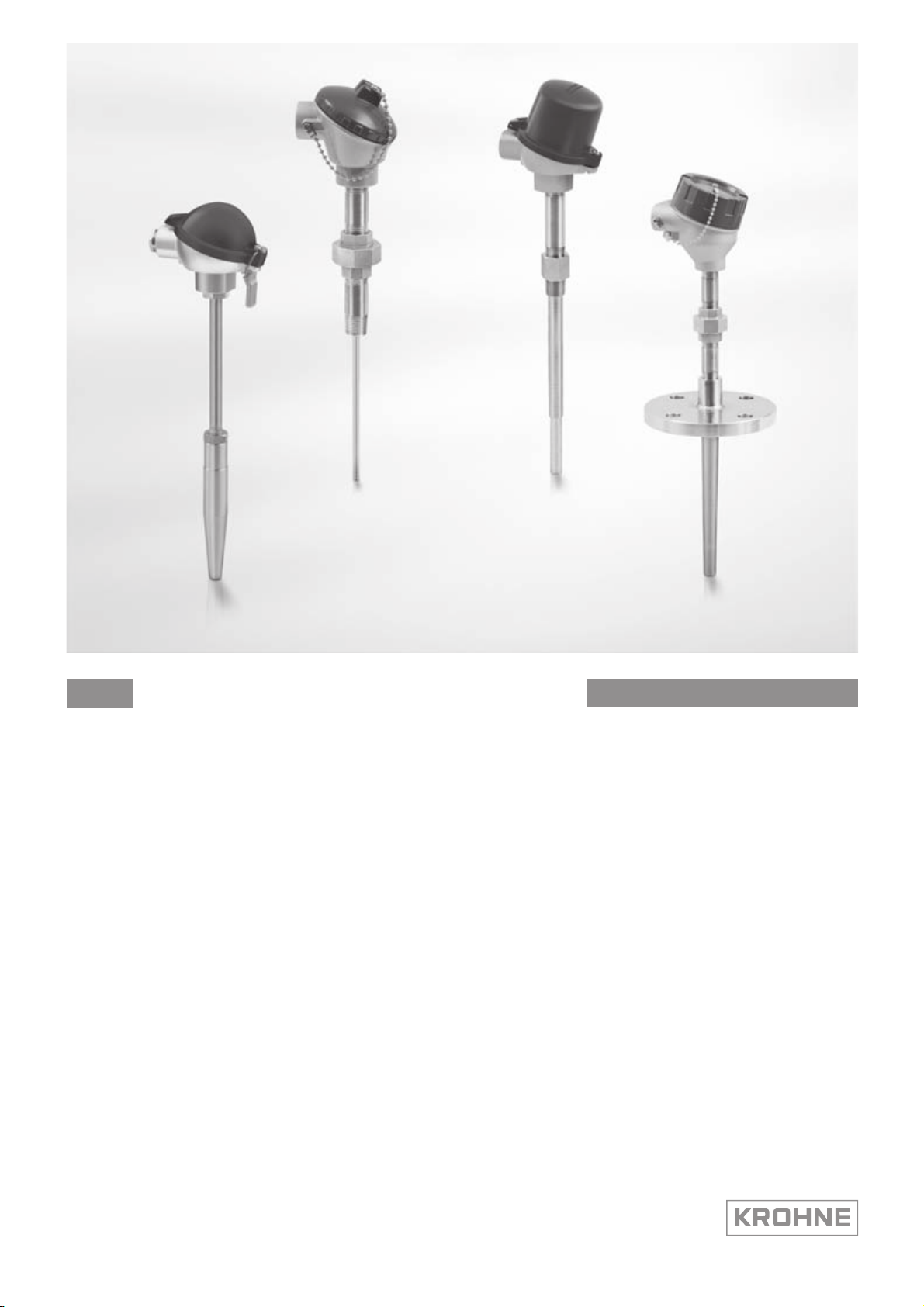
Industrial thermometers for advanced requirements
with replaceable measuring inserts.
HandbookHandbook
© KROHNE 01/2012 - 4000630301 - MA OPTITEMP TRA/TCA Plus R01 en
Page 2

: IMPRINT :::::::::::::::::::::::::::::::::::::::
OPTITEMP TRA/TCA PLUS
All rights reserved. It is prohibited to reproduce this documentation, or any part thereof, without
the prior written authorisation of KROHNE Messtechnik GmbH.
Subject to change without notice.
Copyright 2011 by
KROHNE Messtechnik GmbH - Ludwig-Krohne-Str. 5 - 47058 Duisburg (Germany)
2
www.krohne.com 01/2012 - 4000630301 - MA OPTITEMP TRA/TCA Plus R01
Page 3

OPTITEMP TRA/TCA PLUS
CONTENTS
1 Safety instructions 6
1.1 Intended use ..................................................................................................................... 6
1.2 Approvals and certifications............................................................................................. 6
1.2.1 CE ............................................................................................................................................ 6
1.2.2 ATEX ........................................................................................................................................6
1.3 Safety instructions from the manufacturer ..................................................................... 7
1.3.1 Copyright and data protection ................................................................................................ 7
1.3.2 Disclaimer ............................................................................................................................... 7
1.3.3 Product liability and warranty ................................................................................................ 8
1.3.4 Information concerning the documentation........................................................................... 8
1.3.5 Warnings and symbols used................................................................................................... 9
1.4 Safety instructions for the operator................................................................................. 9
2 Device description 10
2.1 Scope of delivery............................................................................................................. 10
2.2 Device description .......................................................................................................... 11
2.2.1 Design of industrial thermometers for advanced requirements......................................... 11
2.2.2 Types of connection heads.................................................................................................... 12
2.2.3 Measuring insert designs and measuring insert length...................................................... 14
2.2.4 Types of temperature transmitters ...................................................................................... 15
2.2.5 Neck tubes ............................................................................................................................ 17
2.2.6 Thermowells and thermowell tips........................................................................................ 18
2.3 Process connections and areas of application .............................................................. 19
2.3.1 Weld-in thermometer ........................................................................................................... 19
2.3.2 Threaded thermometer ........................................................................................................ 19
2.3.3 Flange thermometer............................................................................................................. 20
2.4 Overview of available versions ....................................................................................... 21
2.5 Nameplate ...................................................................................................................... 25
3 Installation 26
3.1 General notes on installation ......................................................................................... 26
3.2 Storage ........................................................................................................................... 26
3.3 Transport ........................................................................................................................ 26
3.4 Proper installation.......................................................................................................... 27
3.4.1 Possible installations............................................................................................................ 27
3.4.2 Other installation requirements........................................................................................... 28
3.5 Load limits ...................................................................................................................... 29
3.5.1 Typical load types.................................................................................................................. 29
3.5.2 Vibration load ........................................................................................................................ 32
3.5.3 Temperature load ................................................................................................................. 32
3.6 Installation notes on the individual device classes........................................................ 34
3.6.1 Weld-in thermometer ........................................................................................................... 34
3.6.2 Threaded thermometer ........................................................................................................ 35
3.6.3 Flange thermometer............................................................................................................. 36
en
www.krohne.com01/2012 - 4000630301 - MA OPTITEMP TRA/TCA Plus R01
3
Page 4

CONTENTS
OPTITEMP TRA/TCA PLUS
4 Electrical connections 37
4.1 Safety instructions.......................................................................................................... 37
4.2 Grounding ....................................................................................................................... 37
4.3 Protection category ........................................................................................................37
4.4 Power supply .................................................................................................................. 37
5 Operation 38
5.1 Start-up........................................................................................................................... 38
5.2 Normal operation ...........................................................................................................38
5.3 Faults and damage: reason and remedies .................................................................... 38
6 Service 40
6.1 Replacing the electronics............................................................................................... 40
6.2 Cleaning and maintenance............................................................................................. 40
6.3 Spare parts availability...................................................................................................40
6.4 Availability of services .................................................................................................... 40
6.5 Returning the device to the manufacturer..................................................................... 40
6.5.1 General information.............................................................................................................. 40
6.5.2 Form (for copying) to accompany a returned device............................................................ 42
6.6 Disposal .......................................................................................................................... 42
7 Technical data 43
7.1 Measuring principle........................................................................................................43
7.1.1 Resistance thermometer...................................................................................................... 43
7.1.2 Thermocouples ..................................................................................................................... 44
7.2 Technical data tables ..................................................................................................... 45
7.3 Dimensions ..................................................................................................................... 49
7.3.1 Cable gland ........................................................................................................................... 49
7.3.2 Neck tubes ............................................................................................................................ 50
7.3.3 Lengths of thermowells........................................................................................................ 51
7.3.4 Thermowells: Diameter, wall thickness, tips....................................................................... 60
7.3.5 Sleeves .................................................................................................................................. 61
7.3.6 Flanges.................................................................................................................................. 62
7.4 Measuring accuracy ....................................................................................................... 64
7.5 Process connections ...................................................................................................... 65
7.6 Measuring range and permitted load ............................................................................ 66
7.6.1 Operating limits for multipart, welded thermowells ........................................................... 66
7.6.2 Operating limits for one-piece, straight bar stock thermowells ......................................... 67
7.6.3 Operating limits for one-piece, conical bar stock thermowells .......................................... 68
7.6.4 Operating limits for one-piece, reduced bar stock thermowells ........................................ 69
7.6.5 Operating limits for conical weld-in bar stock thermowells ............................................... 71
7.6.6 Operating limits for straight, bar stock weld-in thermowells ............................................. 71
7.7 Permissible temperatures ............................................................................................. 72
7.7.1 Connection head ................................................................................................................... 72
7.7.2 Unloaded thermowell and immersion tubes........................................................................ 72
7.8 Sensor response times .................................................................................................. 73
4
www.krohne.com 01/2012 - 4000630301 - MA OPTITEMP TRA/TCA Plus R01
Page 5

OPTITEMP TRA/TCA PLUS
CONTENTS
8 Appendix 74
8.1 Technical legislation in effect ........................................................................................ 74
9 Notes 75
en
www.krohne.com01/2012 - 4000630301 - MA OPTITEMP TRA/TCA Plus R01
5
Page 6

1 SAFETY INSTRUCTIONS
1.1 Intended use
DANGER!
ATEX approval is pending. Until such approval has been granted, do not install or operate the
industrial thermometer for advanced requirements in potentially hazardous areas. Otherwise
you could cause an explosion that could have fatal consequences.
CAUTION!
Responsibility for the use of the measurement devices with regard to suitability, intended use
and corrosion resistance of the used materials against the measured fluid lies solely with the
operator.
INFORMATION!
The manufacturer is not liable for any damage resulting from improper use or use for other than
the intended purpose.
The thermometer for advanced requirements is used to measure the temperature of gases,
liquids, vapour and solids in industrial applications. The devices are particularly suited to the
measurement of
OPTITEMP TRA/TCA PLUS
• liquids with low viscosity,
• water and chemicals with low corrosiveness,
• saturated steam and superheated steam.
1.2 Approvals and certifications
1.2.1 CE
Article 1, section 2.1.4 of the Pressure Equipment Directive 97/23/EC does not apply to
thermometers for advanced requirements. For this reason, neither a conformity assessment nor
a CE marking is possible. The EC directives applicable to temperature transmitters are
contained in the corresponding transmitter documentation.
1.2.2 ATEX
ATEX approval is pending. As soon as this is available, you have the option of ordering Exapproval according to ATEX. The relevant Ex handbook contains more detailed information.
6
www.krohne.com 01/2012 - 4000630301 - MA OPTITEMP TRA/TCA Plus R01
Page 7

OPTITEMP TRA/TCA PLUS
1.3 Safety instructions from the manufacturer
1.3.1 Copyright and data protection
The contents of this document have been created with great care. Nevertheless, we provide no
guarantee that the contents are correct, complete or up-to-date.
The contents and works in this document are subject to copyright. Contributions from third
parties are identified as such. Reproduction, processing, dissemination and any type of use
beyond what is permitted under copyright requires written authorisation from the respective
author and/or the manufacturer.
The manufacturer tries always to observe the copyrights of others, and to draw on works created
in-house or works in the public domain.
The collection of personal data (such as names, street addresses or e-mail addresses) in the
manufacturer's documents is always on a voluntary basis whenever possible. Whenever
feasible, it is always possible to make use of the offerings and services without providing any
personal data.
SAFETY INSTRUCTIONS 1
We draw your attention to the fact that data transmission over the Internet (e.g. when
communicating by e-mail) may involve gaps in security. It is not possible to protect such data
completely against access by third parties.
We hereby expressly prohibit the use of the contact data published as part of our duty to publish
an imprint for the purpose of sending us any advertising or informational materials that we have
not expressly requested.
1.3.2 Disclaimer
The manufacturer will not be liable for any damage of any kind by using its product, including,
but not limited to direct, indirect or incidental and consequential damages.
This disclaimer does not apply in case the manufacturer has acted on purpose or with gross
negligence. In the event any applicable law does not allow such limitations on implied warranties
or the exclusion of limitation of certain damages, you may, if such law applies to you, not be
subject to some or all of the above disclaimer, exclusions or limitations.
Any product purchased from the manufacturer is warranted in accordance with the relevant
product documentation and our Terms and Conditions of Sale.
The manufacturer reserves the right to alter the content of its documents, including this
disclaimer in any way, at any time, for any reason, without prior notification, and will not be liable
in any way for possible consequences of such changes.
www.krohne.com01/2012 - 4000630301 - MA OPTITEMP TRA/TCA Plus R01
7
Page 8

1 SAFETY INSTRUCTIONS
1.3.3 Product liability and warranty
The operator shall bear responsibility for the suitability of the device for the specific purpose.
The manufacturer accepts no liability for the consequences of misuse by the operator. Improper
installation and operation of the devices (systems) will cause the warranty to be void. The
respective "Standard Terms and Conditions" which form the basis for the sales contract shall
also apply.
1.3.4 Information concerning the documentation
To prevent any injury to the user or damage to the device it is essential that you read the
information in this document and observe applicable national standards, safety requirements
and accident prevention regulations.
If this document is not in your native language and if you have any problems understanding the
text, we advise you to contact your local office for assistance. The manufacturer can not accept
responsibility for any damage or injury caused by misunderstanding of the information in this
document.
This document is provided to help you establish operating conditions, which will permit safe and
efficient use of this device. Special considerations and precautions are also described in the
document, which appear in the form of underneath icons.
OPTITEMP TRA/TCA PLUS
8
www.krohne.com 01/2012 - 4000630301 - MA OPTITEMP TRA/TCA Plus R01
Page 9
OPTITEMP TRA/TCA PLUS
1.3.5 Warnings and symbols used
Safety warnings are indicated by the following symbols.
DANGER!
This information refers to the immediate danger when working with electricity.
DANGER!
This warning refers to the immediate danger of burns caused by heat or hot surfaces.
DANGER!
This warning refers to the immediate danger when using this device in a hazardous atmosphere.
DANGER!
These warnings must be observed without fail. Even partial disregard of this warning can lead to
serious health problems and even death. There is also the risk of seriously damaging the device
or parts of the operator's plant.
SAFETY INSTRUCTIONS 1
WARNING!
Disregarding this safety warning, even if only in part, poses the risk of serious health problems.
There is also the risk of damaging the device or parts of the operator's plant.
CAUTION!
Disregarding these instructions can result in damage to the device or to parts of the operator's
plant.
INFORMATION!
These instructions contain important information for the handling of the device.
LEGAL NOTICE!
This note contains information on statutory directives and standards.
• HANDLING
HANDLING
HANDLINGHANDLING
This symbol designates all instructions for actions to be carried out by the operator in the
specified sequence.
i RESULT
RESULT
RESULTRESULT
This symbol refers to all important consequences of the previous actions.
1.4 Safety instructions for the operator
WARNING!
In general, devices from the manufacturer may only be installed, commissioned, operated and
maintained by properly trained and authorized personnel.
This document is provided to help you establish operating conditions, which will permit safe and
efficient use of this device.
www.krohne.com01/2012 - 4000630301 - MA OPTITEMP TRA/TCA Plus R01
9
Page 10
2 DEVICE DESCRIPTION
2.1 Scope of delivery
INFORMATION!
Inspect the cartons carefully for damages or signs of rough handling. Report damage to the
carrier and to the local office of the manufacturer.
INFORMATION!
Do a check of the packing list to make sure that you have all the elements given in the order.
INFORMATION!
Look at the device nameplate to ensure that the device is delivered according to your order.
The manufacturer delivers all industrial thermometersfor advanced requirements with the
relevant technical documentation. The following table illustrates which thermometer for
advanced requirements is delivered with which documentation (HB = Handbook):
OPTITEMP TRA/TCA PLUS
Scope of order Hb. for
thermometer
s
Thermometer
without
transmitter
Thermometer with
transmitter
Ex-thermometer
without
transmitter
Ex-thermometer
with transmitter
Ex-hb. for
thermometer
s
X - X - -
X - X - X
X X X X -
X X X X X
Hb. for
measuring
inserts
Ex-hb. for
measuring
inserts
Hb. for
transmitters
10
www.krohne.com 01/2012 - 4000630301 - MA OPTITEMP TRA/TCA Plus R01
Page 11
OPTITEMP TRA/TCA PLUS
DEVICE DESCRIPTION 2
2.2 Device description
2.2.1 Design of industrial thermometers for advanced requirements
INFORMATION!
In this documentation, the name "Industrial thermometer for advanced requirements" refers to
thermometer assemblies with multipart, welded thermowells as well as those with one-piece
bar stock thermowells.
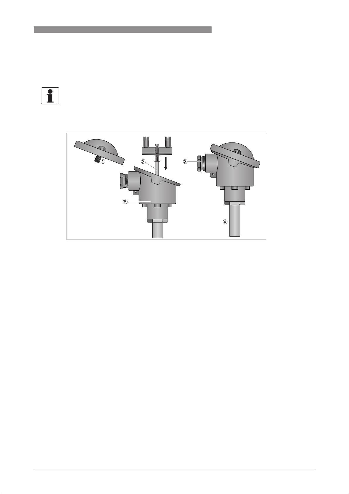
Figure 2-1: Design of an industrial thermometer for advanced requirements
1 Connection head cover
2 Measuring insert
3 Cable gland M20 x 1.5 (only available if the process connection has the dimensions M24 x 1.5, otherwise there is a blind
plug here instead)
4 Neck tube
5 Connection head
All thermometers for advanced requirements consist of a thermowell with process connection, a
neck tube and a connection head. The connection head and the thermowell are largely thermally
decoupled by way of the neck tube. The neck tubes for thermometers with advanced
requirements are available with two different thread types:
• As per DIN: M24 x 1.5 mm
• As per ASME/ANSI: ½"NPT
The connection head is screwed onto the neck tube using the thread. The M24 x 1.5 thread
makes it possible to align the connection head so that the cable gland always faces in the desired
direction (during assembly, the connection head is aligned first before screwing in the thread
using hex nut). In contrast, the alignment of the connection head with ½" NPT threads is only
possible to a limited extent, depending on the type of neck tube.
You can insert either a measuring insert with RTD (OPTITEMP TR 100) or with thermocouple
(OPTITEMP TC 100) into the thermometer assembly. Both measuring inserts are available in
three different versions (for more information see refer to
measuring insert length
(for more information see refer to
on page 14), the manufacturer also offers a variety of thermowell tips
Thermowells and thermowell tips
Measuring insert designs and
on page 18).
www.krohne.com01/2012 - 4000630301 - MA OPTITEMP TRA/TCA Plus R01
11
Page 12
2 DEVICE DESCRIPTION
2.2.2 Types of connection heads
A connection head protects the terminals and the temperature transmitter from environmental
effects (e. g. dirt or dust). The cable gland for the connection head on the industrial thermometer
for advanced requirements depends on the process connection for the connection head
(M20 x 1.5 for process connections with the dimensions M24 x 1.5 and ½" NPT for all process
connections with ½" NPT threads, for more information see refer to
There are oil-resistant rubber seals on the covers of all connection heads (can be used up to
100°C / 212°F ambient temperature). The connection heads are available in the following
materials:
• Die-cast aluminium for standard applications (Types: BA, BUZ-T/S/H/HW, BGK and AXD). The
surface of these connection heads features a 70µm thick powder coating made of polyester.
• Stainless steel (type BVA), especially for the pharmaceutical and food and beverage
industries
• Plastic (type BBK)
The type "BUZ-HW" is the only connection head with an integrated, head-mounted display fed by
the 4...20 mA current loop.
OPTITEMP TRA/TCA PLUS
Cable gland
on page 49).
INFORMATION!
The inside dimensions of the connection heads depicted here comply with DIN 43735.
DANGER!
ATEX approval is pending. Until such approval has been granted, do not install or operate the
industrial thermometer for advanced requirements in potentially hazardous areas. Otherwise
you could cause an explosion that could have fatal consequences.
12
www.krohne.com 01/2012 - 4000630301 - MA OPTITEMP TRA/TCA Plus R01
Page 13
OPTITEMP TRA/TCA PLUS
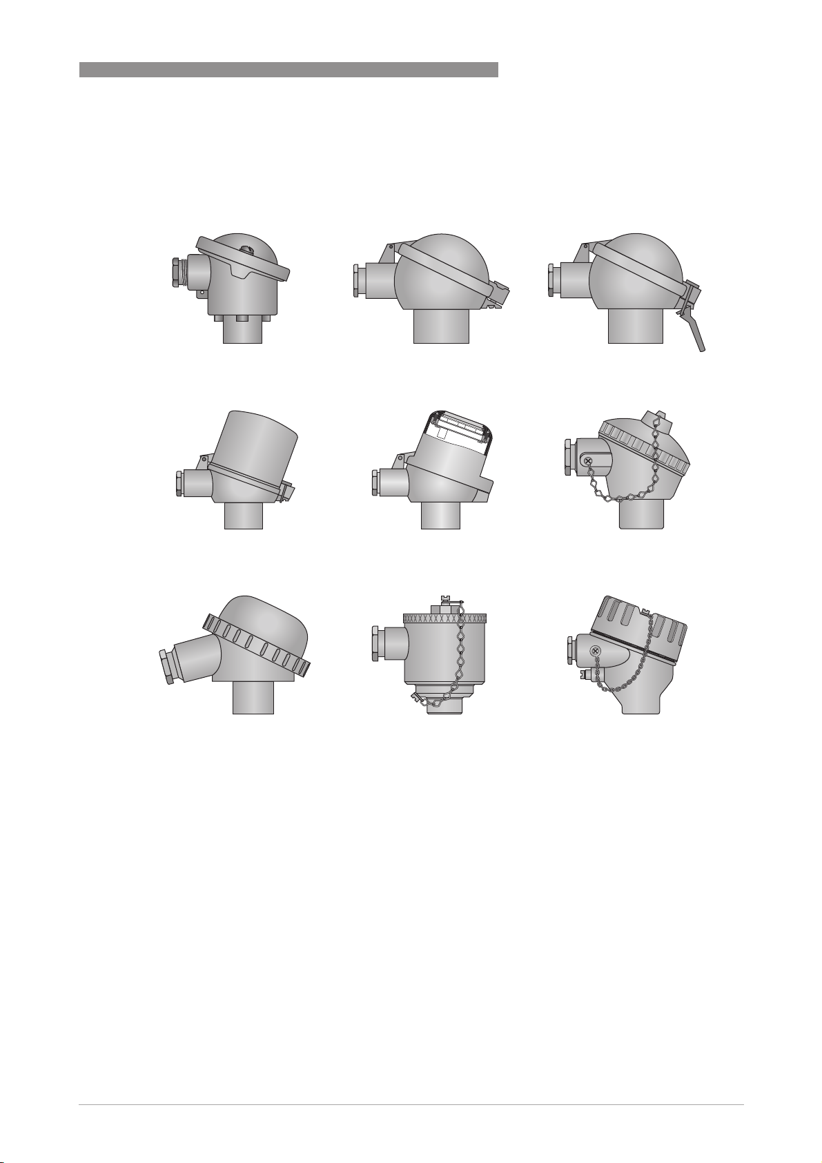
Connection heads available
BA (aluminium, IP65)
BA (aluminium, IP65) BUZ-T (aluminium, IP65)
BA (aluminium, IP65)BA (aluminium, IP65)
BUZ-H (aluminium IP65)
BUZ-H (aluminium IP65) BUZ-HW (aluminium, IP65)
BUZ-H (aluminium IP65)BUZ-H (aluminium IP65)
DEVICE DESCRIPTION 2
BUZ-T (aluminium, IP65) BUZ-S (aluminium, IP65)
BUZ-T (aluminium, IP65)BUZ-T (aluminium, IP65)
BUZ-HW (aluminium, IP65) BGK (aluminium, IP67)
BUZ-HW (aluminium, IP65)BUZ-HW (aluminium, IP65)
BUZ-S (aluminium, IP65)
BUZ-S (aluminium, IP65)BUZ-S (aluminium, IP65)
BGK (aluminium, IP67)
BGK (aluminium, IP67)BGK (aluminium, IP67)
BBK (PA, IP54)
BBK (PA, IP54) BVA (VA, IP65)
BBK (PA, IP54)BBK (PA, IP54)
BVA (VA, IP65) AXD (aluminium, IP68)
BVA (VA, IP65)BVA (VA, IP65)
AXD (aluminium, IP68)
AXD (aluminium, IP68)AXD (aluminium, IP68)
www.krohne.com01/2012 - 4000630301 - MA OPTITEMP TRA/TCA Plus R01
13
Page 14
2 DEVICE DESCRIPTION
2.2.3 Measuring insert designs and measuring insert length
INFORMATION!
The versions, dimensions and other construction features of the measuring inserts are
standardised in DIN 43735.
The replaceable measuring insert contains the temperature sensor, which may be either a Pt100
RTD or a thermocouple. The measuring insert is pushed through the open connection head into
the thermometer assembly and attached using two spring loaded M4 screws (this guarantees
that the tip of the measuring insert is in constant contact with the bottom of the thermowell). The
following versions of measuring insert are available:
OPTITEMP TRA/TCA PLUS
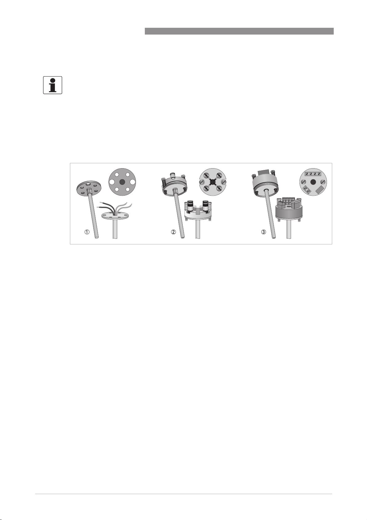
Figure 2-2: Available measuring insert versions
1 Measuring insert with flying wires
2 Measuring insert with ceramic terminal block
3 Measuring insert with head-mounted transmitter
14
www.krohne.com 01/2012 - 4000630301 - MA OPTITEMP TRA/TCA Plus R01
Page 15
OPTITEMP TRA/TCA PLUS
One distinguishing dimension of the measuring insert is its length. The length is measured from
the bottom edge of the base to the tip of the immersion tube ("a" in the drawing below):
Figure 2-3: Measuring insert length
The selection of the right measuring insert depends on the conditions of use:
• A measuring insert with a thermocouple is better suited to heavy thermal or mechanical
loads.
• When increased accuracy is required, a measuring insert with a resistance thermometer is
better suited for temperatures up to +500°C / +932°F and in exceptional cases up to +600°C/
+1112°F.
DEVICE DESCRIPTION 2
INFORMATION!
Consult the handbook "OPTITEMP TR/TC 100" for more detailed information on the measuring
inserts.
2.2.4 Types of temperature transmitters
Electrical thermometers have just one, weak, interference-prone output signal. If this signal has
to travel a great distance or if a standard signal of 4...20 mA is required, use of a temperature
transmitter is recommended:
INFORMATION!
The manufacturer cannot make any general statement as to the distance from which the use of a
temperature transmitter is necessary as it depends on the specific interference associated with
the installation site. The operator alone is responsible for this decision.
There are two types of temperature transmitters:
• Head-mounted transmitter: Located on the measuring insert and thus in the connection head
of the thermometer during operation, recognisable by the "C" in the product name
(e.g.TT10C)
• Rail-mounted transmitter: Located in the control cabinet or field housing, recognisable by
the "R" in the product name (e. g. TT 11 R); they are usually used when the temperature in the
connection head does not allow for the use of a head-mounted transmitter
www.krohne.com01/2012 - 4000630301 - MA OPTITEMP TRA/TCA Plus R01
15
Page 16
2 DEVICE DESCRIPTION
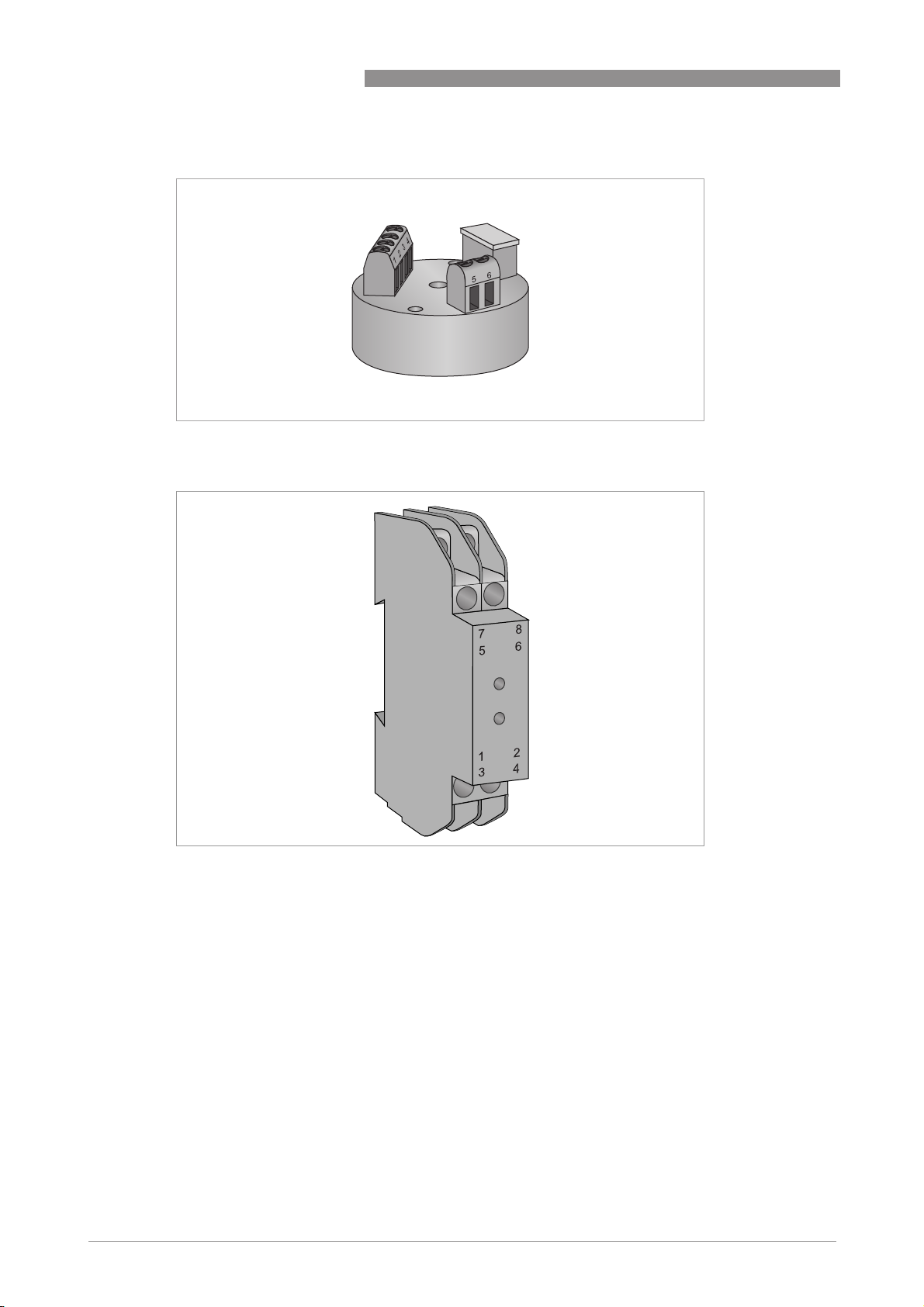
Figure 2-4: Example of a head-mounted transmitter
OPTITEMP TRA/TCA PLUS
16
Figure 2-5: Example of a rail-mounted transmitter
Head-mounted and rail-mounted transmitters both convert the temperature sensor's small
signal into a standardised output signal of 4...20 mA, not susceptible to interference, or into a
digital signal. The output signal depends on the type of temperature transmitter. The following
three 2-wire technology options are currently available:
• 4...20 mA
• 4...20 mA with HART
®
• Profibus-PA
You can parameterise almost any temperature transmitter using a PC and a computer program.
The only exceptions are the TT 10 C/R and TT 11 C/R versions, whose measuring ranges must be
set using solder bridges. The following temperature transmitters are currently available:
www.krohne.com 01/2012 - 4000630301 - MA OPTITEMP TRA/TCA Plus R01
Page 17
OPTITEMP TRA/TCA PLUS
DEVICE DESCRIPTION 2
Available in both head-mounted and railmounted version
TT 10 C/R (analogue, standard, 4...20 mA) TT 31 R (3-wire circuit, 0/4...20 mA, outputs:
TT 11 C/R (analogue, 3- or 4-wire circuit, output:
0...10 VDC)
TT 20 C/R (analogue, 4...20 mA)
TT 30 C/R (digital, 4...20 mA, standard)
TT 40 C/R (digital, 4...20 mA, precise)
TT 50 C/R (digital, 4...20 mA, HART®)
TT 51 C/R (digital, 4...20 mA, HART®, SIL2)
TT 60 C/R (digital, Profibus-PA)
INFORMATION!
Consult the relevant transmitter handbook for more detailed information on the temperature
transmitters.
2.2.5 Neck tubes
The neck tube connects the process connection (i.e. screw socket or flange) to the connection
head. Its function is to largely thermally decouple the connection head so that it and any existing
temperature transmitter do not heat up too much. Depending on both the standard and the
version of the thermowell, there are different threads:
Only available in rail-mounted version
0/1...5 VDC, 0/2...10 VDC)
TT 32 R (4-wire circuit, 0/4...20 mA, outputs:
0/1...5 VDC, 0/2...10 VDC)
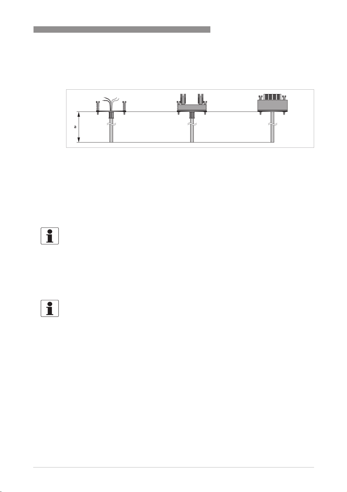
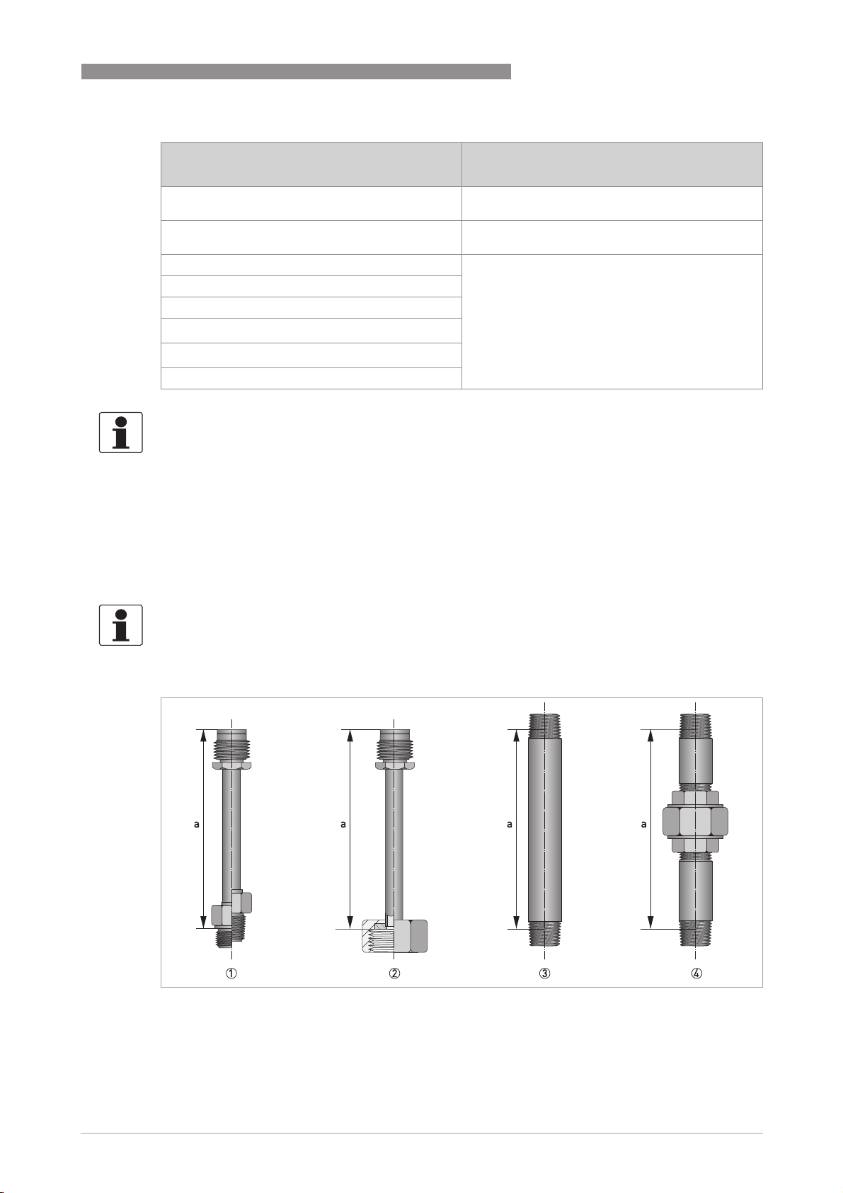
INFORMATION!
The thread for the connection head is the top thread in the following drawing. The dimension "a"
denotes the length of the neck tube.
Figure 2-6: Thread types on neck tubes
1 DIN neck tube, process connection with metric thread (left) and NPT thread (right)
2 DIN neck tube, process connection with union nut
3 ASME neck tube with Nipple-Nipple (NN) connection
4 ASME neck tube with Nipple-Union-Nipple (NUN) connection
www.krohne.com01/2012 - 4000630301 - MA OPTITEMP TRA/TCA Plus R01
17
Page 18
2 DEVICE DESCRIPTION
The neck tubes for industrial thermometers for advanced requirements are made of stainless
steel.
INFORMATION!
The neck tube material may differ from the thermowell material.
The standard neck tube length of a DIN neck tube is 165 mm / 6.5", that of a NUN connection
with ½" NPT thread is 152 mm / 6". Other neck tube lengths are available on request.
2.2.6 Thermowells and thermowell tips
The thermowell is designed to prevent external loads (e. g. static pressure, flowing and
aggressive media) from damaging the measuring insert. As a rule, thermowells are made of the
same material as the system in which the measuring is done. In terms of the material and
design, we can distinguish between two types of thermowells:
• Multipart, welded thermowells
• One-piece bar stock thermowells
OPTITEMP TRA/TCA PLUS
This handbook covers thermometers for advanced requirements such as high pressure and high
flow velocities. For this reason, one-piece thermowells manufactured using bar stock are used
in addition to multipart welded thermowells.
INFORMATION!
The manufacturer checks all of the thermowells for leaks. An optional certified pressure test is
available for a fee.
Thermowells and thermowell tips in different versions are manufactured for the industrial
thermometers for advanced requirements. For more information refer to
Diameter, wall thickness, tips
on page 60.
Thermowells:
All thermowells require a measuring insert with a diameter of 6 mm / 0.24".
Thermowell/thermowell tip Ø Similarity to
standard
[mm] ["]
Straight, multipart, welded 9 / 10 / 11 /12 0.35 / 0.39 / 0.43 /
0.47
Straight, one-piece 17 / 23 0.67 / 0.91 DIN 43772, Form 6, 7
16 / 19 0.63 / 0.75 ASME
Conical, one-piece 24 to 12.5
0.94 to 0.49
16 to 13 0.63 to 0.51 ASME
19 to 16 0.75 to 0.63
22 to 16 0.87 to 0.63
25 to 19 0.98 to 0.75
DIN 43772, Form 5
and 8
and 9
DIN 43772, Form 4
and 4F
18
www.krohne.com 01/2012 - 4000630301 - MA OPTITEMP TRA/TCA Plus R01
Page 19

OPTITEMP TRA/TCA PLUS
Thermowell/thermowell tip Ø Similarity to
[mm] ["]
Reduced tip, one-piece 12 to 9 0.47 to 0.35 ASME
16 to 13 0.63 to 0.51
19 to 13 0.75 to 0.51
19 to 16 0.75 to 0.63
22 to 13 0.87 to 0.51
23 to 13 0.91 to 0.51
INFORMATION!
Both the reduced and the conical tip feature a shorter response time than a straight thermowell.
However, compared to the reduced tip, the conical tip withstands higher pressures.
2.3 Process connections and areas of application
2.3.1 Weld-in thermometer
DEVICE DESCRIPTION 2
standard
Weld-in thermometers for advanced requirements are always the first choice when you want to
measure temperatures in quickly flowing product under high pressure. Compared to threaded
thermometers for advanced requirements, weld-in thermometers are more resilient as they are
not weakened by the notch effect of a thread on the joint.
A typical area of application for weld-in thermometers with advanced requirements is the
measurement of temperature in process vapour lines and cooling water lines, especially in
power plants.
2.3.2 Threaded thermometer
Threaded thermometers with separate neck tubes are particularly well suited to measuring
tasks in process technology or machine building and plant engineering. In this case, screwing
into the pipelines and tanks is the most common process adaption.
The neck tube increases the distance between the process connection and the connection head
so that the latter does not overheat. It also makes it possible to install connection heads outside
of the insulation of pipelines and tanks.
The threaded thermometers for advanced requirements are offered with three different
thermowell shapes forms which are similar to or comply with DIN and ASME standards. These
include a straight thermowell, a conical thermowell and a reduced thermowell. G or NPT thread
variants are available.
www.krohne.com01/2012 - 4000630301 - MA OPTITEMP TRA/TCA Plus R01
19
Page 20

2 DEVICE DESCRIPTION
2.3.3 Flange thermometer
All of the flange thermometers for advanced requirements available from the manufacturer
feature a separate neck tube to thermally decouple the process connection and connection head.
They are typically used in the mid and upper temperature range in industrial applications (up
to +600°C / +1112°F).
Flange thermometers for advanced requirements are predominantly suited to measuring the
temperature in the chemical and petrochemical industries (particularly for pipelines, tanks and
reactors). This area of application opens up because optional coating of the surface is possible.
According to the requirements for chemical resistance, the manufacturer can coat the flange
thermometer with Teflon, PTFE or a customer-specific material.
When it comes to flanges, you can choose between DIN and ASME flanges. The surface
roughness of the flange raised face is R
R
= 3.2...6.3 μm (ASME flanges).
a
As with the threaded thermometers for advanced requirements, the flange thermometers for
advanced requirements also give you the choice between different thermowell forms which are
similar to or comply with valid DIN and ASME standards. Also included are a straight
thermowell, a conical thermowell and a reduced thermowell.
OPTITEMP TRA/TCA PLUS
= 12.5...50 μm (DIN EN flanges) or
z
20
www.krohne.com 01/2012 - 4000630301 - MA OPTITEMP TRA/TCA Plus R01
Page 21
OPTITEMP TRA/TCA PLUS
2.4 Overview of available versions
INFORMATION!
The beginning of the product name refers to the type of sensor in the measuring insert:
•
TRA: Thermometer with Pt100 RTD
•
TCA: Thermometer with thermocouple
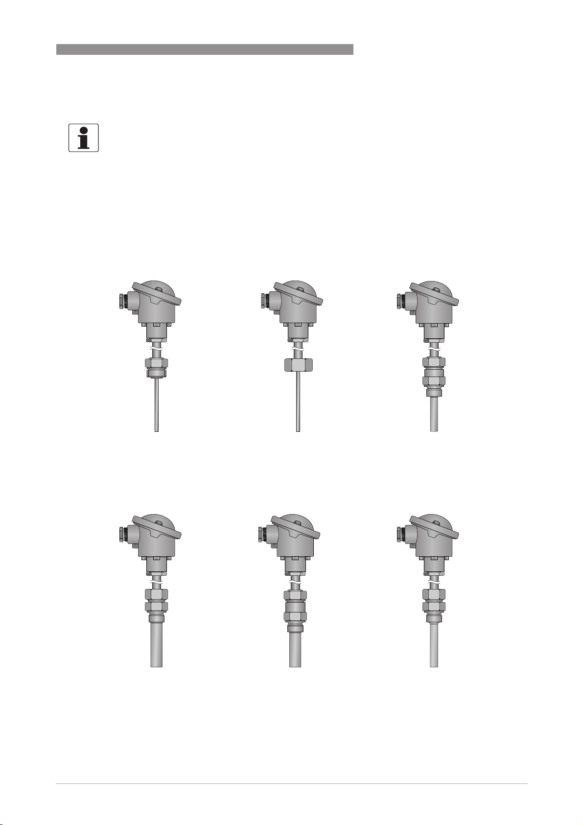
Thermometer with separate neck tube according to DIN 43722
Thermometer with separate neck tube according to DIN 43722
Thermometer with separate neck tube according to DIN 43722Thermometer with separate neck tube according to DIN 43722
Threaded thermometer
TRA / TCA-S34
TRA / TCA-S34 TRA / TCA-S34
TRA / TCA-S34TRA / TCA-S34
TRA / TCA-S34 TRA / TCA-TS32
TRA / TCA-S34TRA / TCA-S34
DEVICE DESCRIPTION 2
TRA / TCA-TS32
TRA / TCA-TS32TRA / TCA-TS32
Connection head with DIN neck
tube, no thermowell
TRA / TCA-TS35
TRA / TCA-TS35 TRA / TCA-TS36
TRA / TCA-TS35TRA / TCA-TS35
Multipart thermowell, neck tube
with union nut, similar to Form 8
Connection head with DIN neck
tube and union nut, no thermowell
TRA / TCA-TS36 TRA / TCA-TS37
TRA / TCA-TS36TRA / TCA-TS36
One-piece thermowell, neck tube
with external thread, similar to
Form 7
Multipart thermowell, neck tube
with external thread, similar to
Form 5
TRA / TCA-TS37
TRA / TCA-TS37TRA / TCA-TS37
One-piece thermowell, neck tube
with union nut, similar to Form 9
www.krohne.com01/2012 - 4000630301 - MA OPTITEMP TRA/TCA Plus R01
21
Page 22
2 DEVICE DESCRIPTION
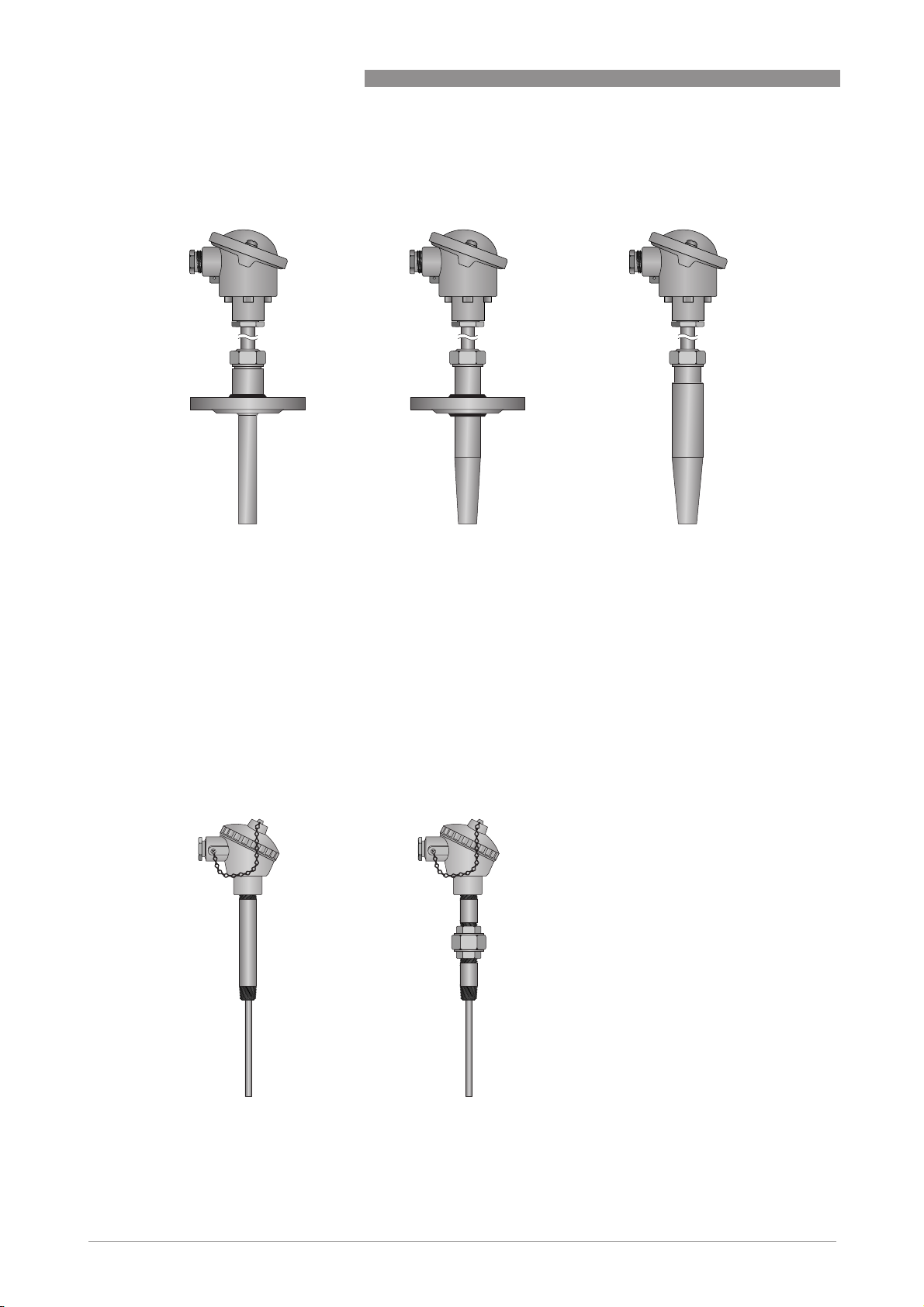
Flange and weld-in thermometers
TRA / TCA-TF33
TRA / TCA-TF33 TRA / TCA-TF31
TRA / TCA-TF33TRA / TCA-TF33
OPTITEMP TRA/TCA PLUS
TRA / TCA-TF31 TRA / TCA-T30
TRA / TCA-TF31TRA / TCA-TF31
TRA / TCA-T30
TRA / TCA-T30TRA / TCA-T30
Multipart thermowell, neck tube
with external thread
Thermometer with separate neck tube according to ASME standard
Thermometer with separate neck tube according to ASME standard
Thermometer with separate neck tube according to ASME standardThermometer with separate neck tube according to ASME standard
One-piece thermowell, neck tube
with external thread, similar to
Form 4F
One-piece thermowell, neck tube
with external thread, similar to
Form 4
Threaded thermometer
TRA / TCA-S50 (NN neck tube)
TRA / TCA-S50 (NN neck tube) TRA / TCA-S50 (NUN neck tube)
TRA / TCA-S50 (NN neck tube)TRA / TCA-S50 (NN neck tube)
TRA / TCA-S50 (NUN neck tube)
TRA / TCA-S50 (NUN neck tube)TRA / TCA-S50 (NUN neck tube)
22
Head with NN neck tube, no
thermowell
Head with NUN neck tube, no
thermowell
www.krohne.com 01/2012 - 4000630301 - MA OPTITEMP TRA/TCA Plus R01
Page 23
OPTITEMP TRA/TCA PLUS
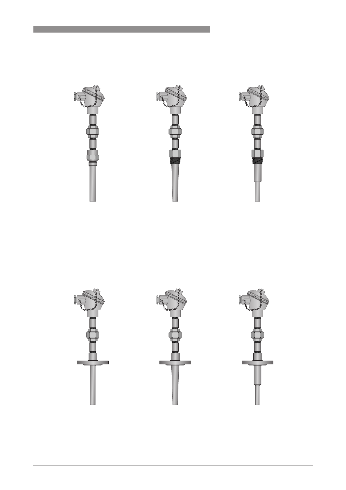
Threaded thermometer
TRA / TCA-TS52
TRA / TCA-TS52 TRA / TCA-TS53
TRA / TCA-TS52TRA / TCA-TS52
DEVICE DESCRIPTION 2
TRA / TCA-TS53 TRA / TCA-TS54
TRA / TCA-TS53TRA / TCA-TS53
TRA / TCA-TS54
TRA / TCA-TS54TRA / TCA-TS54
Screw-in thermowell, one-piece,
straight
Screw-in thermowell, one-piece,
conical
Flange thermometer
TRA / TCA-TF55
TRA / TCA-TF55 TRA / TCA-TF56
TRA / TCA-TF55TRA / TCA-TF55
TRA / TCA-TF56 TRA / TCA-TF57
TRA / TCA-TF56TRA / TCA-TF56
Screw-in thermowell, one-piece,
reduced
TRA / TCA-TF57
TRA / TCA-TF57TRA / TCA-TF57
Flange thermowell, one-piece,
straight
Flange thermowell, one-piece,
conical
www.krohne.com01/2012 - 4000630301 - MA OPTITEMP TRA/TCA Plus R01
Flange thermowell, one-piece,
reduced
23
Page 24

2 DEVICE DESCRIPTION
Weld-in thermometer
TRA / TCA-TW58
TRA / TCA-TW58 TRA / TCA-TW59
TRA / TCA-TW58TRA / TCA-TW58
TRA / TCA-TW59
TRA / TCA-TW59TRA / TCA-TW59
OPTITEMP TRA/TCA PLUS
Weld-in thermowell, one-piece,
straight
Weld-in thermowell, one-piece,
conical
24
www.krohne.com 01/2012 - 4000630301 - MA OPTITEMP TRA/TCA Plus R01
Page 25

OPTITEMP TRA/TCA PLUS
2.5 Nameplate
INFORMATION!
Look at the device nameplate to ensure that the device is delivered according to your order.
The nameplate is located on the connection head, it measures 70 mm x 18 mm / 2.76 x 0.71":
Figure 2-7: Sample nameplate (measuring insert with Pt100 RTD)
1 Manufacturer
2 Production site
3 Manufacturing year
4 Type of thermometer
5 Measuring insert specification
6 Type of temperature transmitter
7 Allowable voltage range of power supply
8 Manufacturer's website
9 Note that the handbook is available for download from the manufacturer's website.
10 Type code
11 Individual serial number
12 VK number
13 Production order number
DEVICE DESCRIPTION 2
INFORMATION!
For a customer-specific TAG No., the manufacturer can print out a separate label if required.
If the thermometer has a transmitter or an Ex approval, this information is found on the right
side of the nameplate.
www.krohne.com01/2012 - 4000630301 - MA OPTITEMP TRA/TCA Plus R01
25
Page 26

3 INSTALLATION
3.1 General notes on installation
DANGER!
For devices used in hazardous areas, additional safety notes apply; please refer to the Ex
documentation.
CAUTION!
Installation, assembly, start-up and maintenance may only be performed by appropriately
trained personnel. The regional occupational health and safety directives must always be
observed.
INFORMATION!
Inspect the cartons carefully for damages or signs of rough handling. Report damage to the
carrier and to the local office of the manufacturer.
INFORMATION!
Do a check of the packing list to make sure that you have all the elements given in the order.
OPTITEMP TRA/TCA PLUS
INFORMATION!
Look at the device nameplate to ensure that the device is delivered according to your order.
INFORMATION!
Assembly materials and tools are not part of the delivery. Use the assembly materials and tools
in compliance with the applicable occupational health and safety directives.
3.2 Storage
CAUTION!
Always store industrial thermometers for advanced requirements in a dry place protected from
dust. The permissible range for storage temperatures is -40...+70
3.3 Transport
CAUTION!
Always transport industrial thermometers for advanced requirements in their original
packaging. Do not expose the devices to moisture or vibration during transport. The information
that applies to storage also applies to transport.
°
C / -40...+176°F.
26
www.krohne.com 01/2012 - 4000630301 - MA OPTITEMP TRA/TCA Plus R01
Page 27

OPTITEMP TRA/TCA PLUS
3.4 Proper installation
CAUTION!
Take the following points into consideration prior to installing the thermometer:
•
The dimensions of the thermowell (length, diameter, wall thickness, type of tip) comply with
the requirements of the measuring point. The mechanical load as a result of flowing media,
vibration and resonances is the focus here. In addition, incorrect dimensions can lead to
measurement errors.
•
The thermowell is sufficiently resistant to chemically aggressive media (refer to the generally
accessible corrosion tables). Otherwise, corrosion may occur or the medium may penetrate
into the thermowell. When in doubt, select a thermowell made from the same material as
your system.
3.4.1 Possible installations
Installations include the parameters "installation site", "installation angle" and "insertion
length". Depending on the space available and the diameter of the pipe, three installations are
recommended for pipes with flowing product:
INSTALLATION 3
• Small pipe diameter: Installation directly against the direction of flow in a bend in the
pipe (1).
• Small pipe diameter: Installation diagonally against the direction of flow, if a bend in the pipe
is available (2).
• Large pipe diameter: Vertical installation, if flow-induced periodic vortex shedding does not
cause the thermometer to vibrate in its resonance frequency (3).
Figure 3-1: Recommended installations
Permitted insertion length of the thermowell or measuring insert
Permitted insertion length of the thermowell or measuring insert
Permitted insertion length of the thermowell or measuring insertPermitted insertion length of the thermowell or measuring insert
The "insertion length" of the thermowell or measuring insert refers to the distance from the seal
of the process connection (for G threads), two-thirds of the thread height (for NPT threads) or the
bottom of the flange (for flange thermometers) to the tip of the thermowell or sheath. This
length determines how far the sensor projects into the measured medium.
www.krohne.com01/2012 - 4000630301 - MA OPTITEMP TRA/TCA Plus R01
27
Page 28

3 INSTALLATION
To avoid measurement errors, ensure that the insertion length ("b" in the drawing below) meets
the following requirements:
• Insertion length = 10...15 x thermowell diameter, but at least 100 mm / 3.94" (shorter
insertion lengths are possible but they impair measuring accuracy).
• Tubes with Ø < 300 mm / 11.8": thermowell tip should project past the middle of the pipe is
possible, if the flow velocity of the product allows it.
OPTITEMP TRA/TCA PLUS
Figure 3-2: Permitted insertion length
INFORMATION!
For more information on the maximum insertion length, please refer to the subsection "Typical
load types".
3.4.2 Other installation requirements
DANGER!
When a seal is damaged or incorrect, the medium may leak out, causing material damage or
bodily harm! It is the sole responsibility of the operator to select the right seal.
• A well-insulated pipeline or tank around the measuring point reduces the heat transfer and
the distorting influence of the ambient temperature.
• To avoid measurement errors caused by poor heat transfer, the measuring insert must
always be in contact with the bottom of the thermowell (this is normally guaranteed by the
spring-loaded version of the measuring insert).
• Choosing the right gasket for the process connection depends on the process conditions; the
manufacturer can thus only give the general recommendation that the gasket must comply
with the individual requirements of the measuring point (e.g. pressure, temperature,
chemically aggressive media).
28
www.krohne.com 01/2012 - 4000630301 - MA OPTITEMP TRA/TCA Plus R01
Page 29

OPTITEMP TRA/TCA PLUS
3.5 Load limits
The load limits of industrial thermometers depend on several factors:
• Dimensions and design of the thermowell (especially the insertion length and diameter)
• Thermowell material
• Mechanical conditions the thermowell is subject to due to the measured medium (pressure,
temperature, flow velocity, viscosity, density)
• Sealable pressure of the process connection
• Vibration load
INFORMATION!
The "sealable pressure" is the maximum pressure the process connection can seal against.
The sheer number of factors at play illustrates the difficulty in making universally valid
statements about the load limits. The diagrams in the next subsection serve as an initial
assessment.
INSTALLATION 3
3.5.1 Typical load types
DANGER!
To prevent destruction or damage, never operate the thermometer outside of its permissible
mechanical, thermal or chemical limits. For further information refer to the rest of this section
and the "Technical data" section.
DANGER!
The information in this subsection is informative only and does not reflect the vibration load
caused by flow-induced eddy shedding and the resulting vibration. If necessary, prior to
purchasing and installing an industrial thermometerfor advanced requirements, have a specific
strength calculation performed (e. g. as per DITTRICH or MURDOCK, ASME PTC 19,3TW-2010).
For further information contact the manufacturer.
INFORMATION!
The manufacturer can provide an optional strength calculation for a fee.
www.krohne.com01/2012 - 4000630301 - MA OPTITEMP TRA/TCA Plus R01
29
Page 30

3 INSTALLATION
The first diagram applies to thermometer(s):
• TRA/TCA-T30 (Form 4)
• Ø 24 x 8.5 mm / 0.94 x 0.33"
• Material 1.4571 / 316 Ti
OPTITEMP TRA/TCA PLUS
Figure 3-3: Load diagram for TRA/TCA-T30
1 Pressure of the measured medium
2 Steam pressure curve
3 Steam
4 Water
5 Insertion length 125 mm or 4.92"; water with 5 m/s or 16.4 ft/s
6 Insertion length 125 mm or 4.92"; steam with 60 m/s or 196.9 ft/s
7 Insertion length 125 mm or 4.92"; air with 60 m/s or 196.9 ft/s
8 Temperature of the measured medium
30
www.krohne.com 01/2012 - 4000630301 - MA OPTITEMP TRA/TCA Plus R01
Page 31

OPTITEMP TRA/TCA PLUS
The second diagram applies to thermometer(s):
• TRA/TCA-TS36 (Form 6 and 7)
• Ø 17 x 5 mm / 0.67 x 0.20"
• Material 1.4571 / 316 Ti
400
360
320
280
240
INSTALLATION 3
200
160
120
80
40
Figure 3-4: Load diagram for TRA/TCA-TS36
1 Pressure of the measured medium
2 Steam pressure curve
3 Steam
4 Water
5 Insertion length 230 mm or 9.06"; water with 3 m/s or 9.8 ft/s
6 Insertion length 230 mm or 9.06"; steam with 40 m/s or 131.2 ft/s
7 Insertion length 230 mm or 9.06"; air with 40 m/s or 131.2 ft/s
8 Temperature of the measured medium
www.krohne.com01/2012 - 4000630301 - MA OPTITEMP TRA/TCA Plus R01
31
Page 32

3 INSTALLATION
3.5.2 Vibration load
CAUTION!
Permanently operating the thermowell in its natural resonance can quickly damage or destroy
the thermometer! So, prior to installation, ensure that this does not happen and select a
thermowell with a different length, a different diameter or another material if necessary.
All thermometers that feature a thermowell and neck tube and are attached to the process
connection have two components that can vibrate: the thermowell and the connection head with
the neck tube. That is why the terms "thermowell resonance" and "head resonance" are
commonly heard.
A thermowell surrounded by the measured medium is a body behind which vortices periodically
are released ("Kármán vortex street"). If the frequency of the vortex detachment is equal to the
resonance frequency of the thermowell, it starts to vibrate. If this happens for a short period of
time, such as when starting up the system and the frequency of the vortex detachment passes
through the resonance range of the thermowell, there is generally no damage is caused. The
opposite is true, however, if the vibrations remain permanently in the resonance range.
3.5.3 Temperature load
OPTITEMP TRA/TCA PLUS
For this reason, all of the industrial thermometers for advanced requirements feature a neck
tube. It causes extensive thermal decoupling and can prevent the connection head and the
temperature transmitter from overheating at high process temperatures.
CAUTION!
When the temperature is too high, the connection head and the components found in it
(e. g. temperature transmitter or display) can be damaged or destroyed! It is your responsibility
as the operator to ensure that the connection head does not get too hot. If this does happen,
select another installation site or lengthen the neck tube or, with insertion-type thermometers,
increase the distance between the connection head and the process connection.
CAUTION!
Sometimes even a neck tube cannot prevent the maximum permissible temperature in the
connection head from being exceeded! It does cause extensive thermal decoupling of the
connection head but you still have to always take into consideration the installation situation as
well as the ambient and process temperatures!
32
www.krohne.com 01/2012 - 4000630301 - MA OPTITEMP TRA/TCA Plus R01
Page 33

OPTITEMP TRA/TCA PLUS
The following diagram will aid in the selection of the right neck tube length and shows how the
process temperature and the neck tube length impact the temperature of the connection head:
CAUTION!
The diagram only shows the amount by which the temperature of the connection head increases.
To determine the actual temperature of the connection head you must add the ambient
temperature to it in a second step!
INSTALLATION 3
Figure 3-5: Heating of the connection head
1 Process temperature +220°C / +428°F
2 Process temperature +400°C / +752°F
3 Process temperature +570°C / +1058°F
4 Temperature of the connection head
5 Neck tube length
INFORMATION!
For more information regarding the maximum allowable temperatures, please refer to the
"Technical data" section.
www.krohne.com01/2012 - 4000630301 - MA OPTITEMP TRA/TCA Plus R01
33
Page 34

3 INSTALLATION
3.6 Installation notes on the individual device classes
3.6.1 Weld-in thermometer
Compared to other types of fastening, welding in thermometers allows for higher process
pressures and flow velocities. Weld-in thermometers can be installed in two different ways:
• Welded in directly: possible in pipes and tanks with a wall thickness ≥20 mm / 0.79"
• Welded in using a welded sleeve: pipes and tanks with a wall thickness < 20 mm / 0.79"
require welding of a sleeve, into which the thermowell is then welded.
The following drawing shows a weld-in sleeve suitable for the TRA/TCA-T30 version:
OPTITEMP TRA/TCA PLUS
Figure 3-6: Welded sleeve for thermometer thermowells according to DIN 43772, Form 4
1 Neck tube
2 Welded sleeve
3 Thermowell
CAUTION!
When installing welded sleeves, always make sure that the transition point between the conical
and straight part of the thermowell is flush with the inner wall of the pipe or tank. You, the user,
are responsible for proper welding, not the manufacturer!
CAUTION!
Sometimes even a neck tube cannot prevent the maximum permissible temperature in the
connection head from being exceeded! It does cause extensive thermal decoupling of the
connection head but you still have to always take into consideration the installation situation as
well as the ambient and process temperatures!
INFORMATION!
For more information on the dimensions of the welded sleeve, please see the
subsection "Dimensions" in the section "Technical Data". Note that the welded sleeve is not
included in the scope of standard delivery but is an optional accessory.
34
www.krohne.com 01/2012 - 4000630301 - MA OPTITEMP TRA/TCA Plus R01
Page 35

OPTITEMP TRA/TCA PLUS
3.6.2 Threaded thermometer
A threaded thermometer can be installed two different ways:
• Screwed in directly: Pipes with a wall thickness ≥ 20 mm / 0.79" make it possible to drill a
hole and cut a thread.
• Screw into threaded sleeves: Pipes with a wall thickness < 20 mm / 0.79" require a sleeve to
be welded in; these are not included in delivery but make up part of the accessories range.
The following drawing shows a threaded jacket suitable for process connections with G½"
threads:
INSTALLATION 3
Figure 3-7: Welded sleeve for threaded thermometer
1 Neck tube with connection head
2 Permanently welded on threaded sleeve
3 Thermowell
CAUTION!
You, the user, are responsible for selecting a suitable sealing material for the process
connection, not the manufacturer! When installing the seals to the process connection, always
ensure a good fit!
CAUTION!
Sometimes even a neck tube cannot prevent the maximum permissible temperature in the
connection head from being exceeded! It does cause extensive thermal decoupling of the
connection head but you still have to always take into consideration the installation situation as
well as the ambient and process temperatures!
INFORMATION!
For more information on the dimensions of the threaded sleeve please see the
subsection "Dimensions" in the section "Technical Data". Note that the threaded sleeve is not
included in the scope of standard delivery but is an optional accessory.
www.krohne.com01/2012 - 4000630301 - MA OPTITEMP TRA/TCA Plus R01
35
Page 36

3 INSTALLATION
3.6.3 Flange thermometer
The flange thermometer can be installed using a weld neck flange, for example, as shown in the
following drawing:
OPTITEMP TRA/TCA PLUS
Figure 3-8: Installing a flange thermometer with a weld neck flange
1 Thermowell with flange as process connection
2 Weld neck flange
3 Pipeline or container wall
CAUTION!
When attaching the flange, tighten the screws evenly and crosswise to avoid leaks at the process
connection.
CAUTION!
You, the user, are responsible for selecting a suitable sealing material for the process
connection, not the manufacturer! When installing the seals to the process connection, always
ensure a good fit!
36
www.krohne.com 01/2012 - 4000630301 - MA OPTITEMP TRA/TCA Plus R01
Page 37

OPTITEMP TRA/TCA PLUS
4.1 Safety instructions
DANGER!
All work on the electrical connections may only be carried out with the power disconnected. Take
note of the voltage data on the nameplate!
DANGER!
Observe the national regulations for electrical installations!
DANGER!
For devices used in hazardous areas, additional safety notes apply; please refer to the Ex
documentation.
WARNING!
Observe without fail the local occupational health and safety regulations. Any work done on the
electrical components of the measuring device may only be carried out by properly trained
specialists.
ELECTRICAL CONNECTIONS 4
INFORMATION!
Look at the device nameplate to ensure that the device is delivered according to your order.
4.2 Grounding
DANGER!
The thermowells on the industrial thermometer for advanced requirements are grounded via the
process connection. No additional grounding is required. One exception is the coated flange
thermowells, which must be grounded separately.
4.3 Protection category
The IP protection category of an industrial thermometer depends on the type of connection and
the cable gland used. Connection heads with ½" NPT threads are supplied without cable glands.
The following protection categories are available: IP54 (BKK), IP65 (BA, BUZ-T/S/H/HW, BVA),
IP67 (BGK), IP68 (AXD).
4.4 Power supply
INFORMATION!
Assembly materials and tools are not part of the delivery. Use the assembly materials and tools
in compliance with the applicable occupational health and safety directives.
The only components of an industrial thermometer for advanced requirements that require a
power supply are the measuring insert and any temperature transmitter used. For more
detailed information on supplying these components with power, consult the product-specific
manuals.
www.krohne.com01/2012 - 4000630301 - MA OPTITEMP TRA/TCA Plus R01
37
Page 38

5 OPERATION
5.1 Start-up
CAUTION!
Double check the following things prior to starting up an industrial thermometer in order to
avoid measuring errors as well as damage to or the destruction of the thermometer:
•
Ensure that the thermowells have been properly installed according to the manufacturer's
instructions.
•
Ensure that the process connection has been successfully tested for leaks.
•
Ensure that the measuring insert sits firmly on the bottom of the thermowell.
•
Ensure that the measuring insert has been properly electrically connected according to the
manufacturer's instructions (refer to measuring insert handbook).
CAUTION!
When operating the transmitters and the display in the BUZ-HW connection head, always refer to
the technical documentation of these devices.
5.2 Normal operation
OPTITEMP TRA/TCA PLUS
During the course of normal operation, it is not necessary to make any adjustments to the
thermometer, measuring insert, temperature transmitter or temperature indicator.
WARNING!
Never touch the thermowell, neck tube or connection head in operation without protective
gloves! These components can become very hot during operation and cause burns.
5.3 Faults and damage: reason and remedies
INFORMATION!
The most probable cause of a fault is the measuring insert itself and its electronic components
(see the handbook for measuring inserts, subsection "Faults: Reasons and Remedies"). The
following issues come into question here:
•
Short circuit or open circuit
•
Insulation resistance too low
•
Ageing
•
Wrong thermocouple wire or compensating line
In addition, the following faults and damage may occur:
Liquid on the process connection
A damaged or incorrect seal can lead to a leak at the process connection. Should this occur,
replace the seal and ensure that the new one meets the individual requirements of the
measuring point (pressure, temperature, chemically aggressive media). It is the sole
responsibility of the operator of the device to select the right seal.
38
www.krohne.com 01/2012 - 4000630301 - MA OPTITEMP TRA/TCA Plus R01
Page 39

OPTITEMP TRA/TCA PLUS
Temperature indication too high or too low
When reference measurements result in an incorrect temperature indication, three causes
come into question:
• Severe heat transfer caused by too short insertion length of thermowell or measuring insert:
the thermometer indicates a temperature that is too low when it is above the ambient
temperature and one that is too high when it is below the ambient temperature.
• Severe heat transfer via the process connection, the pipeline or the tank wall due to a lack of
insulation.
• Incorrect thermowell dimensions (diameter, wall thickness).
To keep the heat transfer to a minimum, either increase the insertion length of the thermometer
or improve the insulation of the measuring point.
Slow response to changes in temperature
If the measuring insert is not resting firmly on the bottom of the thermowell, the response to any
changes in temperature may be slowed. So, ensure that the measuring insert touches the
bottom of the thermowell using the spring-loaded mounting. If the thermometer is to react to
changes in temperature as quickly as possible, thermowells with a tapered or reduced tip are
recommended.
OPERATION 5
Damage to the thermowell and penetrating liquid
If the thermowell is not sufficiently resistant to chemically aggressive media, corrosion may
occur and the measured medium may penetrate. In case of doubt, choose a thermowell made of
the same material as the pipe or tank in which the medium is located.
Breaks or tears
It is possible for breaks or tears to occur due to the force of the media flowing against the
thermowell. It is also possible for vibrations in the resonance range to damage or destroy the
thermowell. Superimposition of the two causes or a combination of insufficient mechanical and
chemical resistance is also possible. The following are starting points for troubleshooting:
• Selection of a thermowell with different dimensions
• Change in neck tube length at critical head resonances
• Selection of a different installation site
www.krohne.com01/2012 - 4000630301 - MA OPTITEMP TRA/TCA Plus R01
39
Page 40

6 SERVICE
6.1 Replacing the electronics
When it comes to industrial thermometers for advanced requirements, it is only possible to
replace an electronic component if there is a temperature transmitter or, if applicable, a headmounted display. Consult the handbook for the temperature transmitter or, if applicable, the
head-mounted display to learn what you need to take into consideration when replacing the
electronics.
6.2 Cleaning and maintenance
As a rule, the industrial thermometers for advanced requirements require no cleaning or
maintenance. However, depending on the conditions of use and the thermal and mechanical
load, they can age. This is true of both measuring inserts with Pt100 RTDs and measuring inserts
with thermocouples.
As a result of the ageing process, the characteristics ("characteristic curve") can change. That
means that the relationship between the electrical resistance (measuring insert with Pt100 RTD)
or the thermovoltage (measuring insert with thermocouple) and the temperature changes. In
this case, calibration shows whether any deviations in measurement values are still within
permissible tolerances.
OPTITEMP TRA/TCA PLUS
6.3 Spare parts availability
The manufacturer adheres to the basic principle that functionally adequate spare parts for each
device or each important accessory part will be kept available for a period of 3 years after
delivery of the last production run for the device.
This regulation only applies to spare parts which are subject to wear and tear under normal
operating conditions.
40
www.krohne.com 01/2012 - 4000630301 - MA OPTITEMP TRA/TCA Plus R01
Page 41

OPTITEMP TRA/TCA PLUS
6.4 Availability of services
The manufacturer offers a range of services to support the customer after expiration of the
warranty. These include repair, maintenance, technical support and training.
INFORMATION!
For more precise information, please contact your local representative.
6.5 Returning the device to the manufacturer
6.5.1 General information
This device has been carefully manufactured and tested. If installed and operated in accordance
with these operating instructions, it will rarely present any problems.
CAUTION!
Should you nevertheless need to return a device for inspection or repair, please pay strict
attention to the following points:
•
Due to statutory regulations on environmental protection and safeguarding the health and
safety of our personnel, manufacturer may only handle, test and repair returned devices that
have been in contact with products without risk to personnel and environment.
•
This means that the manufacturer can only service this device if it is accompanied by the
following certificate (see next section) confirming that the device is safe to handle.
SERVICE 6
CAUTION!
If the device has been operated with toxic, caustic, flammable or water-endangering products,
you are kindly requested:
•
to check and ensure, if necessary by rinsing or neutralizing, that all cavities are free from
such dangerous substances,
•
to enclose a certificate with the device confirming that is safe to handle and stating the
product used.
www.krohne.com01/2012 - 4000630301 - MA OPTITEMP TRA/TCA Plus R01
41
Page 42

6 SERVICE
6.5.2 Form (for copying) to accompany a returned device
Company: Address:
Department: Name:
Tel. no.: Fax no.:
Manufacturer's order no. or serial no.:
The device has been operated with the following medium:
OPTITEMP TRA/TCA PLUS
This medium is: water-hazardous
toxic
caustic
flammable
We checked that all cavities in the device are free from such
substances.
We have flushed out and neutralized all cavities in the
device.
We hereby confirm that there is no risk to persons or the environment through any residual media
contained in the device when it is returned.
Date: Signature:
Stamp:
6.6 Disposal
CAUTION!
Disposal must be carried out in accordance with legislation applicable in your country.
42
www.krohne.com 01/2012 - 4000630301 - MA OPTITEMP TRA/TCA Plus R01
Page 43

OPTITEMP TRA/TCA PLUS
7.1 Measuring principle
All of the thermometers described here belong to the class known as "contact thermometers".
Unlike "radiation thermometers", these thermometers come into direct contact with the
medium whose temperature they are to measure.
The type of measuring principle depends on the measuring insert sensor that you combine with
the transmitter. Two different sensor types are available. Their respective measuring principles
are described in the following subsections.
7.1.1 Resistance thermometer
The measuring insert with a resistance thermometer features a temperature-sensitive sensor
made from a platinum RTD, whose value at 0°C / +32°F is 100 Ω. That is where the name "Pt100"
comes from.
It is generally valid that the electric resistance of metals increases according to a mathematical
function as the temperature rises. This effect is taken advantage of by resistance thermometers
to measure temperature. The "Pt100" thermometer features a measuring resistance with
defined characteristics, standardised in IEC 60751. The same is true for the tolerances. The
average temperature coefficient of a Pt100 is 3.85 x 10
+32...+212°F.
TECHNICAL DATA 7
-3K-1
in the range from 0...+100°C/
During operation, a constant current I (≤ 1 mA) flows through the Pt100 RTD, which brings about
a voltage drop U. The resistance R is calculated using Ohm's Law (R=U/I). As the voltage drop U
at 0°C / +32°F is 100 mV, the resulting resistance of the Pt100 thermometer is 100 Ω (100 mV /
1 mA = 100 Ω).
Figure 7-1: Pt100 resistance thermometer in 4-wire connection at 0°C / +32°F, schematic.
1 Pt100 RTD
2 Voltage meter
3 Current source
www.krohne.com01/2012 - 4000630301 - MA OPTITEMP TRA/TCA Plus R01
43
Page 44

7 TECHNICAL DATA
7.1.2 Thermocouples
The thermocouple features two electric conductors made from different metals, connected at
one end. Each free end is connected to a compensation cable which is then connected to a
millivolt meter. This circuitry forms a "thermal circuit". The point at which the two electric
conductors connect is called the measuring point and the point at which the compensation
cables connect to the conductors of the millivolt meter is called the cold junction.
If the measuring point of this thermal circuit is heated up, a small electrical voltage (thermal
voltage) can be measured. If, however, the measuring point and the cold junction are at the same
temperature, no thermoelectric voltage is generated. The degree of thermoelectric voltage, also
known as electromotive force (EMF), depends on the thermocouple material and the extent of
the temperature difference between the measuring point and the cold junction. It can be
measured using the millivolt meter with no auxiliary power.
Simply put, the thermocouple behaves like a battery, the voltage of which also increases as the
temperature rises.
INFORMATION!
The characteristic curves and tolerances of commercially available thermocouples are
standardised in IEC 60584.
OPTITEMP TRA/TCA PLUS
44
Figure 7-2: Thermocouple measuring circuit, schematic.
1 Measuring point t
2 Thermocouple
3 Transition junction t
4 Compensation cable / extension cable
5 Reference junction t
6 Copper conductor
7 Voltage meter U
(hot junction)
1
2
(cold junction)
3
th
www.krohne.com 01/2012 - 4000630301 - MA OPTITEMP TRA/TCA Plus R01
Page 45

OPTITEMP TRA/TCA PLUS
7.2 Technical data tables
INFORMATION!
•
The following data is provided for general applications. If you require data that is more
relevant to your specific application, please contact us or your local representative.
•
Additional information (certificates, special tools, software,...) and complete product
documentation can be downloaded free of charge from the website (Download Center).
Measuring system
Application range Measuring the temperature of gases, liquids, vapours and solid
Measuring principle Contact thermometer
Measured value Temperature
Design
Modular design Industrial thermometers for advanced requirements consist of
TECHNICAL DATA 7
bodies in industrial processes with advanced requirements (e.g. high
pressure and high flow velocities).
several components which, together, form a thermometer assembly:
• Measuring insert with temperature sensor
• Transmitter (either inside on the measuring insert or outside)
• Connection head
• Separate neck tube
• Thermowell
Signal converter Analogue or digital temperature transmitter in the TT family as head-
Sensor Pt100 RTD as thin layer variant (TF) or as wire wound variant (WW)
Measuring range Refer to "Operating conditions".
Display and user interface
Display and user interface
Display and user interfaceDisplay and user interface
Display Only in connection head "BUZ-HW": 4...20 mA, non-illuminated, LCD,
Operation Only in connection head "BUZ-HW": interior keys.
Display functions
mount or rail-mount transmitter.
with a characteristic according to DIN EN 60751.
Type "J" or "K" thermocouple with a characteristic according to
DIN EN 60584.
loop powered indicator.
Temperature, either as output signal (HART® penetrable) in mA or
scaled to °C/°F.
www.krohne.com01/2012 - 4000630301 - MA OPTITEMP TRA/TCA Plus R01
45
Page 46

7 TECHNICAL DATA
Measuring accuracy
Reference conditions Ambient temperature: +23°C / +73.4°F (fluctuations due to air
Maximum measuring error More detailed information in the subsection "Measurement Error"
Operating conditions
Load limits The load limits depend on several factors (e.g. dimensions, design
Temperature
Temperature
TemperatureTemperature
Process temperature -200...+600°C / -328...+1112°F, depending on measuring insert,
Ambient temperature -40...+100°C / -40...+212°F, depending on connection head and
Storage temperature -40...+70°C / -40...+158°F at 40...60% relative humidity.
Other conditions
Other conditions
Other conditionsOther conditions
Protection categories Depends on the connection head and the cable gland used: IP 54
OPTITEMP TRA/TCA PLUS
pressure and density have no impact on measuring accuracy.)
(also in the "Technical Data" section). The maximum measurement
error also depends on the type of sensor:
• Measuring insert with Pt100 RTD: measurement error in
accordance with tolerance classes A, B, 1/3 B and 1/10 B according
to DIN EN 60751.
• Thermocouple: measurement error in accordance with tolerance
class 1 acc. to DIN EN 60584.
and material of thermowell). Other information can be found in the
"Installation" section or in separate subsections of section "Technical
data".
Thermometer without thermowell: 0.8...1.2 bara / 11.6...17.4 psia.
design and material. Thermometer with thermocouple: Measuring
inserts without thermowell can be used up to 1100°C / 2012°F
measuring insert.
(BKK), IP 65 (BA, BUZ-T/S/H/HW, BVA), IP 67 (BGK), IP 68 (AXD)
Installation conditions
Insertion angle 90° to the flow, directly against or diagonally against the flow.
Insertion length 10...15 x thermowell diameter, minimum 100 mm / 3.94" (shorter
Pipes with Ø ≤ 300 mm / 11.8" The thermowell tip should project past the middle of the pipe.
Pipes with Ø > 300 mm / 11.8" The thermowell tip may only project beyond the middle of the pipe
Bending radius The immersion tubes on the measuring inserts can be bent but the
insertion lengths possible but they impair measuring accuracy).
when the mechanical load permits and the thermowell is not excited
in its resonance; when in doubt, check the individual case again.
smallest bending radius must be at least 3 times the diameter of the
immersion tube.
Note: Do not bend the bottom 50 mm / 2"!
46
www.krohne.com 01/2012 - 4000630301 - MA OPTITEMP TRA/TCA Plus R01
Page 47

OPTITEMP TRA/TCA PLUS
Materials
Thermowells (including process
connection)
Neck tube Standard:
Connection heads Aluminium (powder coated), plastic or stainless steel
Measuring inserts With Pt100 RTD: mineral insulated sheathed cable, sheath material
TECHNICAL DATA 7
The materials of the thermowells, flanges and threads as process
connections are always identical:
Standard:
Standard:
Standard:Standard:
1.4571 / AISI 316 Ti (X6CrNiMoTi 17-12-2)
1.4404 / AISI 316 L (X2CrNiMo 17-12-2)
Optional:
Optional:
Optional:Optional:
1.7335 / no AISI counterpart (13 CrMo4-5)
1.0460 / no AISI counterpart (C22.8)
Standard:
Standard:Standard:
1.4571 / AISI 316 Ti (X6CrNiMoTi 17-12-2)
Optional:
Optional:
Optional:Optional:
1.4404 / AISI 316 L (X2CrNiMo 17-12-2)
1.4404 / AISI 316 L (X2CrNiMo 17-12-2)
With thermocouple: mineral insulated sheathed cable, sheath
material Inconel 600
®
Process connections and connection head thread
Weld-in thermometer with neck
tube
Threaded thermometer with neck
tube
Flange thermometer Acc. to DIN EN 1092-1: B1-DN25 / PN40, B1-DN50 / PN40, other
Connection head There are two thread types available to connect to the neck tube:
Attached using welded sleeves; direct welding is possible starting at
a wall thickness of 20 mm / 0.79".
Weldable threaded sleeves are used to attach; it is possible to screw
directly into the pipe with threads starting at a wall thickness of
20 mm / 0.8".
Available threaded sleeves:
• Thread according to DIN/ISO 228: G½", G¾"
• Thread according to ASME/ANSI B1.20.1: ½"NPT, ¾"NPT
• Other sizes: on request
sizes on request.
Acc. to°ASME B16.5: RF 1" / 150 lb, RF 1" / 300 lb, RF 1" / 600 lb, RF
1½" / 150 lb, RF 1½" / 300 lb, RF 1½" / 600 lb, RF 2" / 150 lb, RF 2" /
300 lb, RF 2" / 600 lb, other sizes on request.
Surface roughness of the flange raised face:
Rz= 12.5...50 μm(DINEN flanges), Ra= 3.2...6.3 μm(ASME flanges).
• Thread according to DIN: M24 x 1.5 mm
• Thread according to ASME/ANSI: ½"NPT(NUN, NN)
www.krohne.com01/2012 - 4000630301 - MA OPTITEMP TRA/TCA Plus R01
47
Page 48

7 TECHNICAL DATA
Electrical connections
Power supply Only necessary when using a temperature transmitter and depends
Power consumption Only when using a temperature transmitter (typically 550 mW).
Cable entry (connection head) Depends on the thread to connect to the neck tube:
Current output
Current output
Current outputCurrent output
Output range Exists only when using a temperature transmitter and depends on
Error signal According to NAMUR NE 43, selectable: upper value ≥ 21.0 mA, lower
Load Relevant only when using a temperature transmitter and then
Other electrical characteristics
Other electrical characteristics
Other electrical characteristicsOther electrical characteristics
Galvanic isolation Relevant only when using a temperature transmitter (see transmitter
Time constant More detailed information can be found in the subsection "Response
OPTITEMP TRA/TCA PLUS
on transmitter type (typically 24 VDC).
• For thread according to DIN: M20 x 1.5
• For thread according to ASME/ANSI: ½" NPT, no cable gland
supplied here.
®
transmitter type (typically 4...20 mA, HART
value ≤ 3.6 mA, the factory default is the upper value.
dependent on transmitter type (typically 250 Ω).
handbook).
times" of the section "Technical data".
, Profibus-PA).
Approvals and certificates
Electromagnetic compatibility See handbook for temperature transmitter used.
ATEX Ex i pending for all thermometers with a measuring insert featuring a
Functional safety SIL2 with temperature transmitter TT51 C/R
diameter of 6 mm / 0.24" and the following sensor:
1 x Pt100, class A, wire-wound RTD.
48
www.krohne.com 01/2012 - 4000630301 - MA OPTITEMP TRA/TCA Plus R01
Page 49

OPTITEMP TRA/TCA PLUS
7.3 Dimensions
7.3.1 Cable gland
Figure 7-3: Cable gland
1 Cable gland
2 Process connection (inner thread)
TECHNICAL DATA 7
Connection head Process connection Cable gland
BA M24x1.5mm M20 x 1.5 mm
BUZ-T M24x1.5mm or ½"NPT M20 x 1.5 mm or ½"NPT
BUZ-S M24x1,5mm M20 x 1,5 mm
BUZ-H M24x1,5mm or ½"NPT M20 x 1,5 mm or ½"NPT
BUZ-HW
BGK
BKK M24x1,5mm M20 x 1,5 mm
BVA
AXD M24x1,5mm or ½"NPT M20 x 1,5 mm or ½"NPT
INFORMATION!
½
For connection heads with
½
" NPT thread versions. Connection heads with ½" NPT threads are supplied without cable
gland. There are no plans for a combination of M24 x 1.5 mm and
" NPT threads, there are process connections and cable glands in
½
"NPT thread.
www.krohne.com01/2012 - 4000630301 - MA OPTITEMP TRA/TCA Plus R01
49
Page 50

7 TECHNICAL DATA
7.3.2 Neck tubes
OPTITEMP TRA/TCA PLUS
Figure 7-4: Neck tubes
1 DIN neck tube with metric screw-in thread (left) and NPT thread (right)
2 DIN neck tube with union nut
3 ASME neck tube with NN connection (Nipple-Nipple)
4 ASME neck tube with NUN connection (Nipple-Union-Nipple)
Type of neck
tube
"a" (neck tube length) "b" (thread for
connection head)
"c" (process connection)
[mm] ["]
1 80 3.15 M24 x 1.5 Thread M18x1.5/ G½"/ ½"NPT
145 5.71
165 6.50
200 7.87
2 80 3.15 M24 x 1,5 Union nut G½" or G¾"
145 5.71
165 6.50
200 7.87
3 76 3 ½"NPT Thread ½"NPT
102 4
4 152 6
50
www.krohne.com 01/2012 - 4000630301 - MA OPTITEMP TRA/TCA Plus R01
Page 51

OPTITEMP TRA/TCA PLUS
7.3.3 Lengths of thermowells
The dimensions for the thermowells and measuring inserts given in this subsection are standard
measurements. Upon request the manufacturer can supply devices with other dimensions. All
industrial thermometers for advanced requirements require a measuring insert with a diameter
of 6 mm / 0.24".
Threaded thermometer without thermowell
TECHNICAL DATA 7
Figure 7-5: Threaded thermometer without thermowell
1 TRA/TCA-S34 (Process connection: thread)
2 TRA/TCA-S34 (Process connection: union nut)
3 TRA/TCA-S50 (Process connection: NPT thread with NN connection)
4 TRA/TCA-S50 (Process connection: NPT thread with NUN connection)
www.krohne.com01/2012 - 4000630301 - MA OPTITEMP TRA/TCA Plus R01
51
Page 52

7 TECHNICAL DATA
TRA/TCA-S34 with DIN-neck tube (neck tube length: 165 mm / 6.5")
Insertion length "b" Measuring insert length
[mm] ["] [mm] ["]
100 3.9 278 10.9
140 5.5 318 12.5
200 7.9 378 14.9
260 10.2 438 17.2
300 11.8 478 18.8
350 13.8 528 20.8
400 15.8 578 22.8
TRA/TCA-S50 with ASME-neck tube (neck tube length: 152 mm / 6.0")
Insertion length "b" Measuring insert length
[mm] ["] [mm] ["]
OPTITEMP TRA/TCA PLUS
100 3.9 281 11.1
150 5.9 331 13.0
200 7.9 381 15.0
250 9.8 431 17.0
300 11.8 481 18.9
350 13.8 531 20.9
400 15.7 581 22.9
INFORMATION!
You can determine the length of the measuring insert for threaded thermometers without
thermowell as follows:
•
TRA/TCA-S34 with DIN neck tube: Measuring insert length = insertion length of the
thermometer assembly + 178 mm / 7.0"
•
TRA/TCA-S50 with ASME neck tube: Measuring insert length = insertion length of
thermometer assembly + 181 mm / 7.1"
INFORMATION!
•
Tolerances of all thermowell and insertion lengths: ±1 mm / 0.04"
•
Tolerances of all measuring insert lengths: +2 mm, -0 mm / +0.08", -0"
52
www.krohne.com 01/2012 - 4000630301 - MA OPTITEMP TRA/TCA Plus R01
Page 53

OPTITEMP TRA/TCA PLUS
Threaded thermometer with thermowell according to DIN 43772
Threaded thermometer with thermowell according to DIN 43772
Threaded thermometer with thermowell according to DIN 43772Threaded thermometer with thermowell according to DIN 43772
TECHNICAL DATA 7
Figure 7-6: Threaded thermometer with thermowell according to DIN 43772
1 TRA/TCA-TS32 (similar to Form 5 as per DIN 43772, with external and internal thread, multipart, welded
2 TRA/TCA-TS36 (similar to Form 6/7 as per DIN 43772, with external and internal thread, one-piece, bar stock)
3 TRA/TCA-TS35 (similar to Form 8 as per DIN 43772, with two external threads, multipart, welded)
4 TRA/TCA-TS37 (similar to Form 9 as per DIN 43772, with two external threads, one-piece, bar stock)
TRA/TCA-TS32 (similar to Form 5)
Neck tube length "a" Insertion length "b" Thermowell length "c" Measuring insert
length
[mm] ["] [mm] ["] [mm] ["] [mm] ["]
165 6.5 82 3.2 110 4.3 287 11.3
142 5.6 170 6.7 347 13.7
232 9.1 260 10.2 437 17.2
382 15.0 410 16.1 587 23.1
TRA/TCA-TS36 (similar to Form 6/7) (bar stock)
Neck tube length "a" Insertion length "b" Thermowell length "c" Measuring insert
length
[mm] ["] [mm] ["] [mm] ["] [mm] ["]
165 6.5 82 3.2 110 4.3 284 11.2
142 5.6 170 6.7 344 13.5
232 9.1 260 10.2 434 17.1
382 15.0 410 16.1 584 23.0
www.krohne.com01/2012 - 4000630301 - MA OPTITEMP TRA/TCA Plus R01
53
Page 54

7 TECHNICAL DATA
TRA/TCA-TS35 (similar to Form 8)
Neck tube length "a" Insertion length "b" Thermowell length "c" Measuring insert
[mm] ["] [mm] ["] [mm] ["] [mm] ["]
165 6.5 110 4.3 138 5.4 314 12.4
TRA/TCA-TS37 (similar to Form 9) (bar stock)
Neck tube length "a" Insertion length "b" Thermowell length "c" Measuring insert
[mm] ["] [mm] ["] [mm] ["] [mm] ["]
165 6.5 110 4.3 138 5.4 311 12.2
OPTITEMP TRA/TCA PLUS
length
170 6.7 198 7.8 374 14.7
260 10.2 288 11.3 464 18.3
410 16.1 438 17.2 614 24.2
length
170 6.7 198 7.8 371 14.6
260 10.2 288 11.3 461 18.1
410 16.1 438 17.2 611 24.1
Threaded thermometer with thermowell according to ASME
Threaded thermometer with thermowell according to ASME
Threaded thermometer with thermowell according to ASMEThreaded thermometer with thermowell according to ASME
Figure 7-7: Threaded thermometer with thermowell according to ASME
1 TRA/TCA-TS52 (straight, with external and internal thread, one-piece, bar stock)
2 TRA/TCA-TS53 (conical, with external and internal thread, one-piece, bar stock)
3 TRA/TCA-TS54 (reduced, with external and internal thread, one-piece, bar stock)
54
The length of the reduced tip "d" is always 65 mm / 2.56".
www.krohne.com 01/2012 - 4000630301 - MA OPTITEMP TRA/TCA Plus R01
Page 55

OPTITEMP TRA/TCA PLUS
TRA/TCA-TS52, -TS53, -TS54 with DIN-neck tube
Neck tube length "a" Insertion length "b" Thermowell length "c" Measuring insert
[mm] ["] [mm] ["] [mm] ["] [mm] ["]
165 6.5 100 3.9 145 5.7 318 12.5
TRA/TCA-TS52, -TS53, -TS54 with ASME-neck tube
Neck tube length "a" Insertion length "b" Thermowell length "c" Measuring insert
[mm] ["] [mm] ["] [mm] ["] [mm] ["]
TECHNICAL DATA 7
length
150 5.9 195 7.7 368 14.5
200 7.9 245 9.6 418 16.5
250 9.8 295 11.6 468 18.4
300 11.8 345 13.6 518 20.4
350 13.8 395 15.6 568 22.4
length
76 3 100 3.9 145 5.7 243 9.6
150 5.9 195 7.7 293 11.5
200 7.9 245 9.6 343 13.5
250 9.8 295 11.6 393 15.5
300 11.8 345 13.6 443 17.4
350 13.8 395 15.6 493 19.4
TRA/TCA-TS52, -TS53, -TS54 with ASME-neck tube
Neck tube length "a" Insertion length "b" Thermowell length "c" Measuring insert
length
[mm] ["] [mm] ["] [mm] ["] [mm] ["]
152 6 100 3.9 145 5.7 319 12.6
150 5.9 195 7.7 369 14.5
200 7.9 245 9.6 419 16.5
250 9.8 295 11.6 469 18.5
300 11.8 345 13.6 519 20.4
350 13.8 395 15.6 569 22.4
www.krohne.com01/2012 - 4000630301 - MA OPTITEMP TRA/TCA Plus R01
55
Page 56

7 TECHNICAL DATA
Flange thermometer according to DIN 43772
Flange thermometer according to DIN 43772
Flange thermometer according to DIN 43772Flange thermometer according to DIN 43772
OPTITEMP TRA/TCA PLUS
Figure 7-8: Flange thermometer according to DIN 43772
1 TRA/TCA-TF31 (conical thermowell, one-piece, bar stock)
2 TRA/TCA-TF33 (straight thermowell, multipart, welded)
TRA/TCA-TF31
Neck tube length
"a"
Insertion length
"b"
Cone length "d" Thermowell
length "c"
Measuring insert
length
[mm] ["] [mm] ["] [mm] ["] [mm] ["] [mm] ["]
165 6.5 130 5.1 65 2.6 200 7.9 375 14.8
190 5 125 4.9 260 10.2 435 17.1
TRA/TCA-TF33
Neck tube length "a" Insertion length "b" Thermowell length "c" Measuring insert
length
[mm] ["] [mm] ["] [mm] ["] [mm] ["]
165 6.5 110 4.3 200 7.9 322 12.7
170 6.7 260 10.2 382 15.0
260 10.2 350 13.8 472 18.6
410 16.1 500 19.7 622 24.5
56
INFORMATION!
•
Tolerances of all thermowell and insertion lengths: ±1 mm / 0.04"
•
Tolerances of all measuring insert lengths: +2 mm, -0 mm / +0.08", -0"
www.krohne.com 01/2012 - 4000630301 - MA OPTITEMP TRA/TCA Plus R01
Page 57

OPTITEMP TRA/TCA PLUS
Flange thermometer according to ASME
Flange thermometer according to ASME
Flange thermometer according to ASMEFlange thermometer according to ASME
TECHNICAL DATA 7
Figure 7-9: Flange thermometer according to ASME
1 TRA/TCA-TF55 (straight thermowell, one-piece, bar stock)
2 TRA/TCA-TF56 (conical thermowell, one-piece, bar stock)
3 TRA/TCA-TF57 (reduced thermowell, one-piece, bar stock)
The length of the reduced tip "d" is always 65 mm / 2.56".
TRA/TCA-TF55, -TF56, -TF57 with DIN- or ASME-Flange
ASME-Neck tube length
"a"
Insertion length "b" Thermowell length
"c"
Measuring insert
length
[mm] ["] [mm] ["] [mm] ["] [mm] ["]
152 6 100 3.9 157 6.2 331 13.0
150 5.9 207 8.1 381 15.0
200 7.9 257 10.1 431 17.0
250 9.8 307 12.1 481 18.9
300 11.8 357 14.1 531 20.9
350 13.8 407 16.0 581 22.9
www.krohne.com01/2012 - 4000630301 - MA OPTITEMP TRA/TCA Plus R01
57
Page 58

7 TECHNICAL DATA
TRA/TCA-TF55, -TF56, -TF57 with DIN- or ASME-Flange
OPTITEMP TRA/TCA PLUS
ASME-Neck tube length
"a"
Insertion length "b" Thermowell length
"c"
Measuring insert
length
[mm] ["] [mm] ["] [mm] ["] [mm] ["]
76 3 100 3.9 157 6.2 255 10.0
150 5.9 207 8.1 305 12.0
200 7.9 257 10.1 355 14.0
250 9.8 307 12.1 405 15.9
300 11.8 357 14.1 455 17.9
350 13.8 407 16.0 505 19.9
TRA/TCA-TF55, -TF56, -TF57 with DIN- or ASME-Flange
DIN-Neck tube length "a" Insertion length "b" Thermowell length
"c"
Measuring insert
length
[mm] ["] [mm] ["] [mm] ["] [mm] ["]
165 6.5 100 3.9 157 6.2 331 13.0
150 5.9 207 8.1 381 15.0
200 7.9 257 10.1 431 17.0
250 9.8 307 12.1 481 18.9
300 11.8 357 14.1 531 20.9
350 13.8 407 16.0 581 22.9
Weld-in thermometer according to DIN 43772 and ASME
Weld-in thermometer according to DIN 43772 and ASME
Weld-in thermometer according to DIN 43772 and ASMEWeld-in thermometer according to DIN 43772 and ASME
58
www.krohne.com 01/2012 - 4000630301 - MA OPTITEMP TRA/TCA Plus R01
Page 59

OPTITEMP TRA/TCA PLUS
Figure 7-10: Weld-in thermometer according to DIN 43772 and ASME
1 TRA/TCA-T30 (conical thermowell with internal thread, one-piece, bar stock)
2 TRA/TCA-TW58 (straight thermowell with internal thread, one-piece, bar stock)
3 TRA/TCA-TW59 (conical thermowell with internal thread, one-piece, bar stock)
TRA/TCA-T30 (similar to Form 4)
TECHNICAL DATA 7
DIN-Neck tube length "a" Thermowell length
"c"
Cone length "d" Measuring insert
length
[mm] ["] [mm] ["] [mm] ["] [mm] ["]
165 6.5 140 5.5 65 2.6 315 12.4
200 7.9 65 2.6 375 14.8
200 7.9 125 4.9 375 14.8
260 10.2 125 4.9 435 17.1
TRA/TCA-TW58 and -TW59
ASME-Neck tube length
"a"
Insertion length "c" Thermowell length
"b"
Measuring insert
length
[mm] ["] [mm] ["] [mm] ["] [mm] ["]
76 3 100 3.9 145 5.7 243 9.6
150 5.9 195 7.7 293 11.5
200 7.9 245 9.6 343 13.5
250 9.8 295 11.6 393 15.5
300 11.8 345 13.6 443 17.4
350 13.8 395 15.6 493 19.4
TRA/TCA-TW58 and -TW59
ASME-Neck tube length
"a"
Thermowell length
"c"
Thermowell length
"c"
Measuring insert
length
[mm] ["] [mm] ["] [mm] ["] [mm] ["]
152 6 100 3.9 145 5.7 319 12.6
150 5.9 195 7.7 369 14.5
200 7.9 245 9.6 419 16.5
250 9.8 295 11.6 469 18.5
300 11.8 345 13.6 519 20.4
350 13.8 395 15.6 569 22.4
www.krohne.com01/2012 - 4000630301 - MA OPTITEMP TRA/TCA Plus R01
59
Page 60

7 TECHNICAL DATA
7.3.4 Thermowells: Diameter, wall thickness, tips
OPTITEMP TRA/TCA PLUS
Figure 7-11: Thermowell designs
1 Straight thermowell, multipart, welded
2 Straight thermowell, one-piece, bar stock
3 Conical-straight thermowell, one-piece, bar stock
4 Conical thermowell, one-piece, bar stock
5 Reduced thermowell, one-piece, bar stock
Type Design Øa Øb (Hole) Øc
[mm] ["] [mm] ["] ["] ["]
TRA/TCA-T30 3 24 h7 0.94 7 0.28 12.5 0.49
TRA/TCA-TF31
TRA/TCA-TS32,
TRA/TCA-TF33,
TRA/TCA-TS35
TRA/TCA-TS36 2 17 0.67 7 0.28
TRA/TCA-TS37 2 17 0.67 7 0.28
TRA/TCA-TS52 2 16 0.63 6.5 0.26
TRA/TCA-TS53 4 16 0.63 6.5 0.26 13 0.51
TRA/TCA-TS54 5 16 0.63 6.5 0.26 13 0.51
TRA/TCA-TF55 2 19 0.75 6.5 0.26 - -
TRA/TCA-TF56 4 22 0.87 6.5 0.26 16 0.63
1 9x1 0.37 x 0.04 7 0.28 - -
10 x 1 0.41 x 0.04 8 0.31
11 x 2 0.45 x 0.08 7 0.28
12 x 2 0.49 x 0.08 8 0.31
12 x 2.5 0.49 x 0.10 7 0.28
22 0.87 6.5 0.26 16 0.63
22 0.87 6.5 0.26 13 0.51
25 0.98 6.5 0.26 19 0.75
60
www.krohne.com 01/2012 - 4000630301 - MA OPTITEMP TRA/TCA Plus R01
Page 61

OPTITEMP TRA/TCA PLUS
Type Design Øa Øb (Hole) Øc
TRA/TCA-TF57 5 12 0.47 6.5 0.26 9 0.35
TRA/TCA-TW58 2 19 0.75 6.5 0.26 - -
TRA/TCA-TW59 4 19 0.75 6.5 0.26 16 0.63
7.3.5 Sleeves
Weld-in sleeve for TRA/TCA-T30
TECHNICAL DATA 7
[mm] ["] [mm] ["] ["] ["]
19 0.75 6.5 0.26 13 0.51
23 0.91 6.5 0.26 13 0.51
23 0.91 6.5 0.26
25 0.98 6.5 0.26 19 0.75
[mm] ["]
a 48 1.89
b 24 G7 0.94
c 50 1.97
d 30 1.18
www.krohne.com01/2012 - 4000630301 - MA OPTITEMP TRA/TCA Plus R01
61
Page 62

7 TECHNICAL DATA
Threaded sleeve for process connections with G½" thread
[mm] ["]
OPTITEMP TRA/TCA PLUS
a (thread) 12.7 ½
b 50 / 100 1.97 / 3.94
c 29 1.14
d 40 1.57
7.3.6 Flanges
INFORMATION!
Upon request the manufacturer can supply flanges with dimensions other than those specified
here.
Dimensions of flange acc. to DIN EN 1092-1, raised face B1
62
Type of flange a b c d
[mm] ["] [mm] ["] [mm] ["] [mm] ["]
B1-DN25 / PN40
(EN 1092-1)
B1-DN50 / PN40
(EN 1092-1)
14 0.55 18 0.71 85 3.35 115 4.53
18 0.71 20 0.79 125 4.92 165 6.50
www.krohne.com 01/2012 - 4000630301 - MA OPTITEMP TRA/TCA Plus R01
Page 63

OPTITEMP TRA/TCA PLUS
Dimensions of flange acc. to ASME/ANSI 16.5, raised face RF
Type of flange a b c d
TECHNICAL DATA 7
[mm] ["] [mm] ["] [mm] ["] [mm] ["]
RF 1" / 150 lb
(ASME B16.5)
RF 1" / 300 lb
(ASME B16.5)
RF 1" / 600 lb
(ASME B16.5)
RF 1½"/ 150lb
(ASME B16.5)
RF 1½"/ 300lb
(ASME B16.5)
RF 1½"/ 600lb
(ASME B16.5)
RF 2" / 150 lb
(ASME B16.5)
RF 2" / 300 lb
(ASME B16.5)
RF 2" / 600 lb
(ASME B16.5)
15.9 0.63 14.7 0.58 79.4 3.13 110 4.33
19.1 0.75 17.9 0.70 88.9 3.50 125 4.92
19.1 0.75 24.5 0.96 88.9 3.50 125 4.92
15.9 0.63 17.9 0.70 98.4 3.87 125 4.92
22.3 0.88 21.1 0.83 114.3 4.50 155 6.10
22.3 0.88 29.3 1.15 114.3 4.50 155 6.10
19.1 0.75 19.5 0.77 120.7 4.75 150 5.91
19.1 0.75 22.7 0.89 127 5.00 165 6.50
19.1 0.75 32.4 1.28 127 5.00 165 6.50
www.krohne.com01/2012 - 4000630301 - MA OPTITEMP TRA/TCA Plus R01
63
Page 64

7 TECHNICAL DATA
7.4 Measuring accuracy
The measuring accuracy depends largely on the following factors:
• The version of the measuring insert (type of sensor, type of circuit, measuring range).
• The correct dimensions (diameter, wall thickness) and insertion length of the thermowell for
good thermal coupling to the process temperature (insufficient insertion depth often results
in measurement errors).
• The type of temperature transmitter used.
INFORMATION!
Please consult the appropriate handbook for further information regarding the accuracy of the
measuring inserts and the temperature transmitters.
With the exception of the TT 60 C/R version, all of the temperature transmitters generate an
analogue output signal. For this reason, the following table indicates the measuring accuracy of
most of the transmitters as a percentage of the measuring range:
Temperature transmitter
OPTITEMP TRA/TCA PLUS
Type of temperature transmitter Accuracy (% of the measuring range or °K)
TT 10 C/R (analogue, standard, 4...20 mA) ± 0.15%
TT 11 C/R (analogue, 3- or 4-wire circuit:
0...10 VDC)
TT 20 C/R (analogue, 4...20 mA) ± 0.10%
TT 30 C/R (digital, 4...20 mA, standard) ± 0.10%
TT 31 R (3-wire-circuit, 4...20 mA ± 0.10%
TT 32 R (4-wire circuit, 0/4...20 mA: 0/2...10 VDC) ± 0.20%
TT 40 C/R (digital, 4...20 mA, precise) ± 0.05%
TT 50 C/R (digital, 4...20 mA, HART®)
TT 51 C/R (digital, 4...20 mA, HART®, SIL2)
TT 60 C/R (digital, Profibus-PA) ± 0.10°K
± 0.15%
± 0.10%
± 0.05%
64
www.krohne.com 01/2012 - 4000630301 - MA OPTITEMP TRA/TCA Plus R01
Page 65

OPTITEMP TRA/TCA PLUS
7.5 Process connections
Threaded thermometer without thermowell
Process connection Materials Ø of neck tube
Thread M18x1.5mm 1.4571 12 x 2.5 0.47 x 0.1
Thread G½", G¾"
Union nut G½", G¾"
Thread ½" NPT (NN and NUN) 1.4404 21.34 x 2.77 0.84 x 0.11 SCH 40
Threaded thermometer with thermowell
Process connection Materials Ø of thermowell
TECHNICAL DATA 7
[mm] ["]
[mm] ["]
Thread G½", G¾" 1.4571 / AISI 316 Ti,
Thread ½"NPT, ¾"NPT
1.4404 / AISI 316 L
9, 10, 11, 12, 6, 17,220.35, 0.39, 0.43, 0.47,
0.63, 0.67, 0.87
Flange thermometer
Process connection Materials Ø of thermowell
[mm] ["]
DN25 / PN40 1.4571 / AISI 316 Ti,
DN50 / PN40
1" / 150 lb, 300 lb, 600 lb
1½" / 150 lb, 300 lb, 600 lb
2" / 150 lb, 300 lb, 600 lb
1.4404 / AISI 316 L
9, 10, 11, 12, 19, 22,
23, 25
0.35, 0.39, 0.43, 0.47,
0.75, 0.87, 0.98
INFORMATION!
The manufacturer offers the flange thermometer with process connections acc. to DIN EN 10921 or ASME/ANSI 16.5. For DIN flanges the raised face complies with Form B1 and with ASME
flanges, type "RF" or type "RTJ".
Weld-in thermometer
Ø at the weld-in point Materials Ø of thermowell
[mm] ["] [mm] ["]
24 h7 0.94 1.4571 / AISI 316 Ti,
1.4404 / AISI 316 L,
1.7335 / AISI F12,
1.0460 / C 22.8
26.7 1.05 1.4571 / AISI 316 Ti,
1.4404 / AISI 316 L
33.4 1.31 1.4571 / AISI 316 Ti,
1.4404 / AISI 316 L
www.krohne.com01/2012 - 4000630301 - MA OPTITEMP TRA/TCA Plus R01
24 h7 0.94
19 0.75
23, 25 0.91, 0.98
65
Page 66

7 TECHNICAL DATA
7.6 Measuring range and permitted load
DANGER!
To prevent fatal injuries or damage, never operate the thermometer outside of its permissible
mechanical, thermal or chemical limits. For further information refer to the rest of this section
and the "Technical data" section.
DANGER!
The information in this subsection is informative only and does not reflect the vibration load
caused by flow-induced eddy shedding and the resulting vibration. If necessary, prior to
purchasing and installing an industrial thermometerfor advanced requirements, have a specific
strength calculation performed (e. g. as per DITTRICH or MURDOCK, ASME PTC 19,3TW-2010).
For further information contact the manufacturer.
CAUTION!
To prevent destruction or damage, only operate a thermometer without a thermowell in the
range of 0.8...1.2 bara / 11.6...17.4 psia.
INFORMATION!
The manufacturer can provide an optional strength calculation for a fee.
OPTITEMP TRA/TCA PLUS
Temperatures that can be measured with an industrial thermometer depend largely on the load
of the thermometer. Load limits are defined through a variety of factors (see the subsection
"Load limits" in the "Installation" section). For this reason, the manufacturer cannot make any
universally valid statements about the measuring range and permissible load.
INFORMATION!
The thermowell operating limits specified below refer to a flow of air of 40 m/s or 131.2 ft/s or a
flow of water or vapour of 5 m/s or 16.4 ft/s.
7.6.1 Operating limits for multipart, welded thermowells
TRA/TCA-TS32, -TF33 and -TS35 with Ø 12 x 2.5 mm / 0.47 x 0.10"
Process connection Material Insertion length p
[mm] ["] [bar] [psi] [bar] [psi]
Thread G½", G¾",
½"NPT, ¾"NPT
Flanges ASME 1",
1½", 2" 150 lb
Flanges ASME 1",
1½", 2" 300 lb
Flanges ASME 1",
1½", 2" 600 lb
Flanges DN25, DN50
PN40
1.4571 /
316 Ti
82 3.2 100 / 100 1450 / 1450 100 / 100 1450 / 1450
382 15.0 14.1 / 17.9 204 / 259 33.7 / 100 488 / 1450
110 4.3 19.0 / 6.5 276 / 94 19.0 / 6.5 276 / 94
410 16.1 12.3 / 15.6 179 / 94 3.4 / 6.5 49 / 94
110 4.3 49.6 / 29.4 719 / 426 49.6 / 29.4 719 / 426
410 16.1 12.3 / 15.6 179 / 226 3.4 / 29.4 49 / 426
110 4.3 99.3 / 58.9 1440 / 854 99.3 / 58.9 1440 / 854
410 16.1 12.3 / 15.6 179 / 226 3.4 / 58.9 49 / 854
160 6.3 40.0 / 31.2 580 / 452 40.0 / 31.2 580 / 452
at +20°C / +400°C or
max
+68°F / +752°F, air
p
at +20°C / +400°C or
max
+68°F / +752°F, water /
vapour
66
www.krohne.com 01/2012 - 4000630301 - MA OPTITEMP TRA/TCA Plus R01
Page 67

OPTITEMP TRA/TCA PLUS
TECHNICAL DATA 7
7.6.2 Operating limits for one-piece, straight bar stock thermowells
TRA/TCA-TS36 and -TS37 with Ø 17 x 5 mm / 0.67 x 0.2"
Process connection Material Insertion length p
[mm] ["] [bar] [psi] [bar] [psi]
Thread G½", G¾",
½"NPT, ¾"NPT
1.4571 /
316 Ti,
1.4404 /
316 L
82 3.2 100 / 100 1450 / 1450 100 / 100 1450 / 1450
382 15.0 31.1 / 39.5 451 / 572 100 / 100 1450 / 1450
TRA/TCA-TS52 with Ø 16 x 4.75 mm / 0.63 x 0.19"
Process connection Material Insertion length p
[mm] ["] [bar] [psi] [bar] [psi]
Thread G½", G¾",
½"NPT, ¾"NPT
1.4571 /
316 Ti,
1.4404 /
316 L
100 3.9 100 / 100 1450 / 1450 100 / 100 1450 / 1450
300 11.8 44.8 / 56.7 649 / 822 100 / 100 1450 / 1450
TRA/TCA-TF55 with Ø 19 x 6.25 mm / 0.75 x 0.25"
Process connection Material Insertion length p
at +20°C / +400°C or
max
+68°F / +752°F, air
at +20°C / +400°C or
max
+68°F / +752°F, air
at +20°C / +400°C or
max
+68°F / +752°F, air
p
at +20°C / +400°C or
max
+68°F / +752°F, water /
vapour
p
at +20°C / +400°C or
max
+68°F / +752°F, water /
vapour
p
at +20°C / +400°C or
max
+68°F / +752°F, water /
vapour
Flanges ASME 1",
1½", 2" 150 lb
Flanges ASME 1",
1½", 2" 300 lb
Flanges ASME 1",
1½", 2" 600 lb
Flanges DN25, DN50
PN40
1.4404 /
316 L
[mm] ["] [bar] [psi] [bar] [psi]
100 3.9 15.9 / 6.5 231 / 94 15.9 / 6.5 231 / 94
300 11.8 15.9 / 6.5 231 / 94 15.9 / 6.5 231 / 94
100 3.9 41.4 / 24.3 600 / 352 41.4 / 24.3 600 / 352
300 11.8 41.4 / 24.3 600 / 352 41.4 / 24.3 600 / 352
100 3.9 82.7 / 48.6 1199 / 705 82.7 / 48.6 1199 / 705
300 11.8 62.0 / 48.6 899 / 705 82.7 / 48.6 1199 / 705
100 3.9 40.0 / 25.7 580 / 373 40.0 / 25.7 580 / 352
300 11.8 40.0 / 25.7 580 / 580 40.0 / 25.7 580 / 373
www.krohne.com01/2012 - 4000630301 - MA OPTITEMP TRA/TCA Plus R01
67
Page 68

7 TECHNICAL DATA
7.6.3 Operating limits for one-piece, conical bar stock thermowells
TRA/TCA-TS53 with Ø 16 to 13 mm / 0.63 to 0.51"
OPTITEMP TRA/TCA PLUS
Process connection Material Insertion length p
[mm] ["] [bar] [psi] [bar] [psi]
Thread G½", G¾",
½"NPT, ¾"NPT
1.4571 /
316 Ti,
1.4404 /
316 L
100 3.9 100 / 100 1450 / 1450 100 / 100 1450 / 1450
300 11.8 50.0 / 62.8 725 / 910 100 / 100 1450 / 1450
TRA/TCA-TS53 with Ø 22 to 16 mm / 0.87 to 0.63"
Process connection Material Insertion length p
[mm] ["] [bar] [psi] [bar] [psi]
Thread G½", G¾",
½"NPT, ¾"NPT
1.4571 /
316 Ti,
1.4404 /
316 L
100 3.9 100 / 100 1450 / 1450 100 / 100 1450 / 1450
300 11.8 100 / 100 1450 / 1450 100 / 100 1450 / 1450
TRA/TCA-TF56 with Ø 22 to 16 mm / 0.87 to 0.63"
Process connection Material Insertion length p
at +20°C / +400°C or
max
+68°F / +752°F, air
at +20°C / +400°C or
max
+68°F / +752°F, air
at +20°C / +400°C or
max
+68°F / +752°F, air
p
at +20°C / +400°C or
max
+68°F / +752°F, water /
vapour
p
at +20°C / +400°C or
max
+68°F / +752°F, water /
vapour
p
at +20°C / +400°C or
max
+68°F / +752°F, water /
vapour
Flanges ASME 1",
1½", 2" 150 lb
Flanges ASME 1",
1½", 2" 300 lb
Flanges ASME 1",
1½", 2" 600 lb
Flanges DN25, DN50
PN40
1.4404 /
316 L
[mm] ["] [bar] [psi] [bar] [psi]
100 3.9 15.9 / 6.5 231 / 94 15.9 / 6.5 231 / 94
300 11.8 15.9 / 6.5 231 / 94 15.9 / 6.5 231 / 94
100 3.9 41.4 / 24.3 600 / 352 41.4 / 24.3 600 / 352
300 11.8 41.4 / 24.3 600 / 352 41.4 / 24.3 600 / 352
100 3.9 82.7 / 48.6 1199 / 705 82.7 / 48.6 1199 / 705
300 11.8 82.7 / 48.6 1199 / 705 82.7 / 48.6 1199 / 705
100 3.9 40.0 / 25.7 580 / 373 40.0 / 25.7 580 / 373
300 11.8 40.0 / 25.7 580 / 373 40.0 / 25.7 580 / 373
68
www.krohne.com 01/2012 - 4000630301 - MA OPTITEMP TRA/TCA Plus R01
Page 69

OPTITEMP TRA/TCA PLUS
TRA/TCA-TF56 with Ø 25 to 19 mm / 0.98 to 0.75"
TECHNICAL DATA 7
Process connection Material Insertion length p
at +20°C / +400°C or
max
+68°F / +752°F, air
[mm] ["] [bar] [psi] [bar] [psi]
Flanges ASME 1",
1½", 2" 150 lb
Flanges ASME 1",
1½", 2" 300 lb
Flanges ASME 1",
1½", 2" 600 lb
Flanges DN25, DN50
PN40
1.4404 /
316 L
100 3.9 15.9 / 6.5 231 / 94 15.9 / 6.5 231 / 94
300 11.8 15.9 / 6.5 231 / 94 15.9 / 6.5 231 / 94
100 3.9 41.4 / 24.3 600 / 352 41.4 / 24.3 600 / 352
300 11.8 41.4 / 24.3 600 / 352 41.4 / 24.3 600 / 352
100 3.9 82.7 / 48.6 1199 / 705 82.7 / 48.6 1199 / 705
300 11.8 82.7 / 48.6 1199 / 705 82.7 / 48.6 1199 / 705
100 3.9 40.0 / 25.7 580 / 373 40.0 / 25.7 580 / 373
300 11.8 40.0 / 25.7 580 / 373 40.0 / 25.7 580 / 373
7.6.4 Operating limits for one-piece, reduced bar stock thermowells
TRA/TCA-TS54 with Ø 16 to 13 mm / 0.63 to 0.51"
Process connection Material Insertion length p
at +20°C / +400°C or
max
+68°F / +752°F, air
p
at +20°C / +400°C or
max
+68°F / +752°F, water /
vapour
p
at +20°C / +400°C or
max
+68°F / +752°F, water /
vapour
[mm] ["] [bar] [psi] [bar] [psi]
Thread G½", G¾",
½"NPT, ¾"NPT
1.4571 /
316 Ti,
1.4404 /
316 L
100 3.9 100 / 100 1450 / 1450 100 / 100 1450 / 1450
300 11.8 47.0 / 59.0 681 / 855 100 / 100 1450 / 1450
TRA/TCA-TS54 with Ø 22 to 13 mm / 0.87 to 0.51"
Process connection Material Insertion length p
[mm] ["] [bar] [psi] [bar] [psi]
Thread G½", G¾",
½"NPT, ¾"NPT
1.4571 /
316 Ti,
1.4404 /
316 L
100 3.9 100 / 100 1450 / 1450 100 / 100 1450 / 1450
300 11.8 97.0 / 100 1406 / 1450 100 / 100 1450 / 1450
at +20°C / +400°C or
max
+68°F / +752°F, air
p
at +20°C / +400°C or
max
+68°F / +752°F, water /
vapour
www.krohne.com01/2012 - 4000630301 - MA OPTITEMP TRA/TCA Plus R01
69
Page 70

7 TECHNICAL DATA
TRA/TCA-TF57 with Ø 12 to 9 mm / 0.47 to 0.35"
OPTITEMP TRA/TCA PLUS
Process connection Material Insertion length p
[mm] ["] [bar] [psi] [bar] [psi]
Flanges ASME 1",
1½", 2" 150 lb
Flanges ASME 1",
1½", 2" 300 lb
Flanges ASME 1",
1½", 2" 600 lb
Flanges DN25, DN50
PN40
1.4404 /
316 L
100 3.9 15.9 / 6.5 231 / 94 15.9 / 6.5 231 / 94
300 11.8 15.9 / 6.5 231 / 94 15.9 / 6.5 231 / 94
100 3.9 41.4 / 24.3 600 / 352 41.4 / 24.3 600 / 352
300 11.8 25.8 / 24.3 374 / 352 41.4 / 24.3 600 / 352
100 3.9 82.7 / 48.6 1199 / 705 82.7 / 48.6 1199 / 705
300 11.8 25.8 / 32.7 374 / 474 82.7 / 48.6 1199 / 705
100 3.9 40.0 / 25.7 580 / 373 40.0 / 25.7 580 / 373
300 11.8 25.8 / 25.7 374 / 373 40.0 / 25.7 580 / 373
TRA/TCA-TF57 with Ø 19 to 13 mm / 0.75 to 0.51"
Process connection Material Insertion length p
[mm] ["] [bar] [psi] [bar] [psi]
Flanges ASME 1",
1½", 2" 150 lb
Flanges ASME 1",
1½", 2" 300 lb
Flanges ASME 1",
1½", 2" 600 lb
Flanges DN25, DN50
PN40
1.4404 /
316 L
100 3.9 15.9 / 6.5 231 / 94 15.9 / 6.5 231 / 94
300 11.8 15.9 / 6.5 231 / 94 15.9 / 6.5 231 / 94
100 3.9 41.4 / 24.3 600 / 352 41.4 / 24.3 600 / 352
300 11.8 41.4 / 24.3 600 / 352 41.4 / 24.3 600 / 352
100 3.9 82.7 / 48.6 1199 / 705 82.7 / 48.6 1199 / 705
300 11.8 70.0 / 48.6 1015 / 705 82.7 / 48.6 1199 / 705
100 3.9 40.0 / 25.7 580 / 373 40.0 / 25.7 580 / 373
300 11.8 40.0 / 25.7 580 / 373 40.0 / 25.7 580 / 373
at +20°C / +400°C or
max
+68°F / +752°F, air
at +20°C / +400°C or
max
+68°F / +752°F, air
p
at +20°C / +400°C or
max
+68°F / +752°F, water /
vapour
p
at +20°C / +400°C or
max
+68°F / +752°F, water /
vapour
TRA/TCA-TF57 with Ø 23 to 13 mm / 0.91 to 0.51"
Process connection Material Insertion length p
[mm] ["] [bar] [psi] [bar] [psi]
Flanges ASME 1",
1½", 2" 150 lb
Flanges ASME 1",
1½", 2" 300 lb
Flanges ASME 1",
1½", 2" 600 lb
Flanges DN25, DN50
PN40
70
1.4404 /
316 L
100 3.9 15.9 / 6.5 231 / 94 15.9 / 6.5 231 / 94
300 11.8 15.9 / 6.5 231 / 94 15.9 / 6.5 231 / 94
100 3.9 41.4 / 24.3 600 / 352 41.4 / 24.3 600 / 352
300 11.8 41.4 / 24.3 600 / 352 41.4 / 24.3 600 / 352
100 3.9 82.7 / 48.6 1199 / 705 82.7 / 48.6 1199 / 705
300 11.8 82.7 / 48.6 1199 / 705 82.7 / 48.6 1199 / 705
100 3.9 40.0 / 25.7 580 / 373 40.0 / 25.7 580 / 373
300 11.8 40.0 / 25.7 580 / 373 40.0 / 25.7 580 / 373
www.krohne.com 01/2012 - 4000630301 - MA OPTITEMP TRA/TCA Plus R01
at +20°C / +400°C or
max
+68°F / +752°F, air
p
at +20°C / +400°C or
max
+68°F / +752°F, water /
vapour
Page 71

OPTITEMP TRA/TCA PLUS
TECHNICAL DATA 7
7.6.5 Operating limits for conical weld-in bar stock thermowells
TRA/TCA-T30 with Ø 24 h7 to 12.5 mm / 0.95 to 0.49"
Ø at the process
connection
Material Insertion length / cone
length
p
at +20°C / +400°C
max
or +68°F / +752°F, air
p
at +20°C/+400°C
max
or +68°F / +752°F,
water / vapour
[mm] ["] [mm] ["] [bar] [psi] [bar] [psi]
24 h7 0.95 1.4571 /
316 Ti
1.4404 /
316 L
1.7335 /
AISI F12
200 / 65 7.9 / 2.6 245 / 195 3553 / 2828 343 / 195 4974 / 2828
260 / 125 10.2 / 4.9 158 / 187 2291 / 2712 343 / 195 4974 / 2828
200 / 65 7.9 / 2.6 245 / 195 3553 / 2828 343 / 195 4974 / 2828
260 / 125 10.2 / 4.9 158 / 187 2291 / 2712 343 / 195 4974 / 2828
200 / 65 7.9 / 2.6 332 / 343 4815 / 4974 442 / 343 6410 / 4974
260 / 125 10.2 / 4.9 207 / 338 3002 / 4902 443 / 343 6410 / 4974
TRA/TCA-TW59 with various diameters
Ø at the process
connection
[mm] ["] [mm] ["] [bar] [psi] [bar] [psi]
26.7
19 to 16
33.4
25 to 19
1.05
0.75 to 0.63
1.31
0.98 to 0.75
Material Insertion length p
1.4404 /
316 L
100 3.9 371 / 230 5380 / 3335 414 / 235 6004 / 3408
300 11.8 69.0 / 86.0 1000 / 1247 400 / 235 5801 / 3408
100 3.9 423 / 249 6135 / 3611 439 / 250 6367 / 3625
300 11.8 125 / 152 1812 / 2204 438 / 250 6352 / 3625
at +20°C / +400°C
max
or +68°F / +752°F, air
p
at +20°C / +400°C
max
or +68°F / +752°F,
water / vapour
7.6.6 Operating limits for straight, bar stock weld-in thermowells
TRA/TCA-TW58 with various diameters
Ø at the process
connection
[mm] ["] [mm] ["] [bar] [psi] [bar] [psi]
26.7
19
33.4
23
1.05
0.75
1.31
0.91
Material Insertion length p
1.4404 /
316 L
100 3.9 364 / 228 5279 / 3306 436 / 249 6323 / 3611
300 11.8 62.0 / 79.0 899 / 1145 401 / 244 5816 / 3538
100 3.9 402 / 244 5830 / 3538 456 / 260 6613 / 3770
300 11.8 91.0 / 113 1319 / 1638 434 / 257 6294 / 3727
at +20°C / +400°C
max
or +68°F / +752°F, air
p
at +20°C / +400°C
max
or +68°F / +752°F,
water / vapour
www.krohne.com01/2012 - 4000630301 - MA OPTITEMP TRA/TCA Plus R01
71
Page 72

7 TECHNICAL DATA
7.7 Permissible temperatures
7.7.1 Connection head
OPTITEMP TRA/TCA PLUS
Temperature
Connection head Temperature range Maximum temperature
transmitter
Material Display
without Metal no -40...+100°C/
without Plastic no -40...+80°C/
with Metal no -40...+85°C/
with Plastic no -40...+80°C/
with Metal Yes -40...+70°C/
7.7.2 Unloaded thermowell and immersion tubes
The temperatures specified in the following tables are valid only for thermowells and immersion
tubes that do not project into flowing media or media under pressure. The maximum permissible
temperature is reduced under load.
DANGER!
If you are unsure as to whether the device can withstand the loads of the process when using an
insertion-type thermometer without thermowell, have a separate strength calculation done (e.g.
per DITTRICH or MURDOCK, ASME PTC 10.9-TW)! For further information contact the
manufacturer.
-40...+212°F
-40...+176°F
-40...+185°F
-40...+176°F
-40...+158°F
limiting component
Gasket of connection head
cover and cable gland
Connection head material
Temperature transmitter
Connection head material
Display
INFORMATION!
The manufacturer can provide an optional strength calculation for a fee.
Thermowells
Type of
thermowell
-T30 1.4571 / AISI 316 Ti -200...+600°C / -328...+1112°F
All others 1.4571 / AISI 316 Ti -200...+600°C / -328...+1112°F
Material Permissible temperature range
1.4404 / AISI 316 L -200...+600°C / -328...+1112°F
1.7335 / AISI F12 -200...+550°C / -328...+1022°F
1.0460 / C22.8 -200...+550°C / -328...+1022°F
1.4404 / AISI 316 L -200...+600°C / -328...+1112°F
Sheaths of measuring inserts made of mineral insulated cable
Type of sensor Cable jacket material Permissible temperature range
Pt100 RTD 1.4404 / AISI 316 L -200...+600°C / -328...+1112°F
Thermocouple
Inconel®600
-40...+1100°C / -40...+1832°F
72
www.krohne.com 01/2012 - 4000630301 - MA OPTITEMP TRA/TCA Plus R01
Page 73

OPTITEMP TRA/TCA PLUS
7.8 Sensor response times
Thermometer response times are generally indicated as "50% time" (t05) and "90% time" (t09).
"50% time" refers to the time needed for a thermometer signal to achieve 50% of its end value in
the face of erratic temperature changes (this applies analogously to "90% time").
INFORMATION!
You can find more information about response times in VDI 3522.
Thermometer with welded, straight thermowell
Ø of thermowell Pt100 RTD Thermocouple
[mm] ["] t05[s] t09[s] t05[s] t09[s]
9 0.35 17 52 14 42
11 0.43 21 58 17 46
12 0.47 22 66 18 54
Water flows against the thermometer at 0.4 m/s or 1.31 ft/s
TECHNICAL DATA 7
Thermometer without thermowell (TRA/TCA-S34 and -S50 with Ø 6 mm / 0.24")
Sensor Water with 0.4 m/s or 1.31 ft/s Air with 1 m/s or 3.28 ft/s
t05[s] t09[s] t05[s] t09[s]
Pt100 RTD 3.5 8 24 54
Thermocouple 2.5 7 21 50
www.krohne.com01/2012 - 4000630301 - MA OPTITEMP TRA/TCA Plus R01
73
Page 74

8 APPENDIX
8.1 Technical legislation in effect
Standard Title
VDE/VDI 3511 Technical temperature measurements
VDI/VDE 3522 Response time of contact thermometers.
DIN 43735 Control technology - Electrical temperature sensors - replaceable measuring
DIN 43771 Measurement, control; electrical temperature sensor; thermometer with short
DIN 43772 Control technology - Metal thermowells and neck tubes for machine glass
DIN 43772,
Supplementary sheet
2
inserts for resistance thermometers and thermocouples
response time
thermometers, dial thermometers, thermocouples and resistance
thermometers - dimensions, materials, testing
Control technology - Metal thermowells and neck tubes for machine glass
thermometers, dial thermometers, thermocouples and resistance
thermometers - calculation of thermowells
OPTITEMP TRA/TCA PLUS
74
www.krohne.com 01/2012 - 4000630301 - MA OPTITEMP TRA/TCA Plus R01
Page 75

OPTITEMP TRA/TCA PLUS
NOTES 9
www.krohne.com01/2012 - 4000630301 - MA OPTITEMP TRA/TCA Plus R01
75
Page 76

KROHNE product overview
• Electromagnetic flowmeters
• Variable area flowmeters
• Ultrasonic flowmeters
• Mass flowmeters
• Vortex flowmeters
• Flow controllers
• Level meters
• Temperature meters
• Pressure meters
• Analysis products
• Measuring systems for the oil and gas industry
• Measuring systems for sea-going tankers
Head Office KROHNE Messtechnik GmbH
Ludwig-Krohne-Str. 5
D-47058 Duisburg (Germany)
Tel.:+49 (0)203 301 0
Fax:+49 (0)203 301 10389
info@krohne.de
© KROHNE 01/2012 - 4000630301 - MA OPTITEMP TRA/TCA Plus R01 en - Subject to change without notice.
The current list of all KROHNE contacts and addresses can be found at:
www.krohne.com
 Loading...