

Page 1
Quick Start
Quick Start
TIDALFLUX 4300 F
TIDALFLUX 4300 F
TIDALFLUX 4300 FTIDALFLUX 4300 F
Quick Start Quick Start
Electromagnetic flow sensor for partially filled pipes
The documentation is only complete when used in combination with the relevant
documentation for the converter.
© KROHNE 09/2010 - 7308302300 - QS TIDALFLUX 4000 R03 en
Page 2

CONTENTS
TIDALFLUX 4300 F
1 Safety instructions 3
2 Installation 4
2.1 Scope of delivery............................................................................................................... 4
2.2 Transport .......................................................................................................................... 4
2.3 Installation conditions ...................................................................................................... 5
2.3.1 Inlet and outlet........................................................................................................................ 5
2.3.2 Mounting position.................................................................................................................... 5
2.3.3 Flange deviation...................................................................................................................... 6
2.3.4 Vibration .................................................................................................................................. 6
2.3.5 Magnetic field.......................................................................................................................... 6
2.3.6 Control valve ........................................................................................................................... 7
2.3.7 Slope........................................................................................................................................ 7
2.3.8 Mounting advice for difficult situations .................................................................................. 7
2.3.9 Cleaning of flow sensor .......................................................................................................... 8
2.3.10 Temperatures ....................................................................................................................... 8
2.4 Mounting........................................................................................................................... 9
2.4.1 Mounting grounding rings ...................................................................................................... 9
2.4.2 Torques and pressures........................................................................................................... 9
3 Electrical connections 11
3.1 Safety instructions.......................................................................................................... 11
3.2 Important notes on electrical connection...................................................................... 11
3.3 Connection of cables ...................................................................................................... 12
3.4 Cable lengths.................................................................................................................. 13
3.5 Signal cable A (type DS 300), construction .................................................................... 15
3.6 Preparing signal cable A, connection to measuring sensor ......................................... 16
3.7 Signal cable B (type BTS 300), construction .................................................................. 17
3.8 Preparing signal cable B, connection to measuring sensor ......................................... 17
3.9 Preparing field current cable C, connection to measuring sensor............................... 19
3.10 Interface cable.............................................................................................................. 21
3.11 Grounding ..................................................................................................................... 22
4 Start-up 23
4.1 Switching on the power .................................................................................................. 23
5 Technical data 24
5.1 Dimensions and weights ................................................................................................ 24
5.2 Vacuum load ................................................................................................................... 25
6 Notes 26
2
www.krohne.com 09/2010 - 7308302300 - QS TIDALFLUX 4000 R03 en
Page 3
TIDALFLUX 4300 F
Warnings and symbols used
DANGER!
This information refers to the immediate danger when working with electricity.
DANGER!
These warnings must be observed without fail. Even partial disregard of this warning can lead to
serious health problems and even death. There is also the risk of seriously damaging the device
or parts of the operator's plant.
WARNING!
Disregarding this safety warning, even if only in part, poses the risk of serious health problems.
There is also the risk of damaging the device or parts of the operator's plant.
CAUTION!
Disregarding these instructions can result in damage to the device or to parts of the operator's
plant.
INFORMATION!
These instructions contain important information for the handling of the device.
SAFETY INSTRUCTIONS 1
HANDLING
• This symbol designates all instructions for actions to be carried out by the operator in the
specified sequence.
i RESULT
RESULT
RESULTRESULT
This symbol refers to all important consequences of the previous actions.
Safety instructions for the operator
CAUTION!
Installation, assembly, start-up and maintenance may only be performed by appropriately
trained personnel. The regional occupational health and safety directives must always be
observed.
LEGAL NOTICE!
The responsibility as to the suitability and intended use of this device rests solely with the user.
The supplier assumes no responsibility in the event of improper use by the customer. Improper
installation and operation may lead to loss of warranty. In addition, the "Terms and Conditions of
Sale" apply. They appear on the back of the invoice and form the basis of the purchase contract.
INFORMATION!
•
Further information can be found on the supplied CD-ROM in the manual, on the data sheet,
in special manuals, certificates and on the manufacturer's website.
•
If you need to return the device to the manufacturer or supplier, please fill out the form
contained on the CD-ROM and send it with the device. Unfortunately, the manufacturer
cannot repair or inspect the device without the completed form.
www.krohne.com09/2010 - 7308302300 - QS TIDALFLUX 4000 R03 en
3
Page 4
2 INSTALLATION
2.1 Scope of delivery
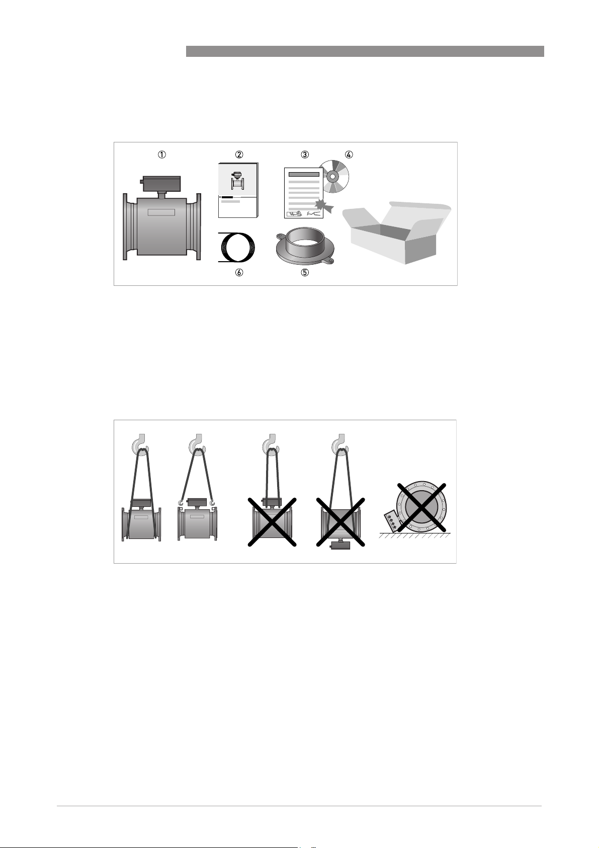
Figure 2-1: Scope of delivery
1 Ordered flowmeter
2 Product documentation
3 Factory calibration report
4 CD-ROM with product documentation
5 Grounding rings (optionally)
6 Cable
TIDALFLUX 4300 F
2.2 Transport
Figure 2-2: Transport
4
www.krohne.com 09/2010 - 7308302300 - QS TIDALFLUX 4000 R03 en
Page 5
TIDALFLUX 4300 F
2.3 Installation conditions
2.3.1 Inlet and outlet
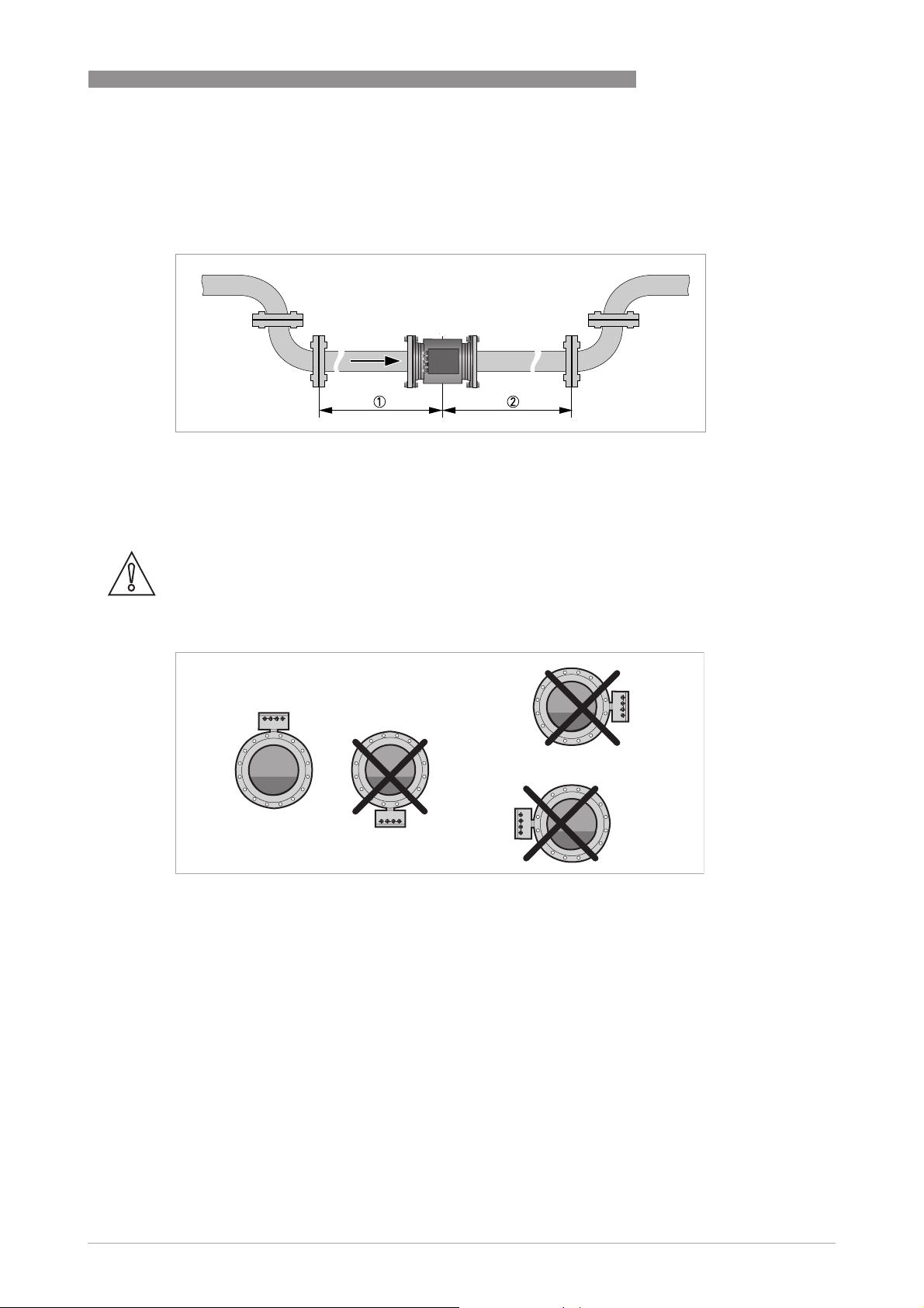
Figure 2-3: Recommended inlet and outlet sections, top view
1 ≥ 5 DN
2 ≥ 3 DN
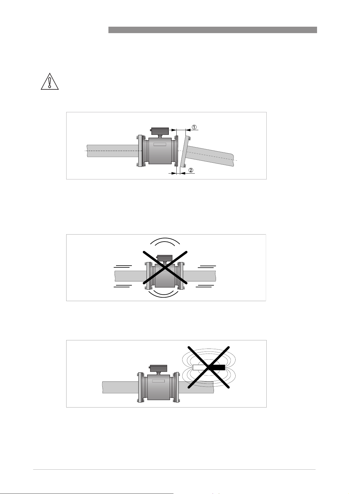
2.3.2 Mounting position
INSTALLATION 2
CAUTION!
Only install the flow sensor in the shown position to keep the electrodes under water. Limit the
±2°
rotation to
Figure 2-4: Mounting position
to maintain the accuracy.
www.krohne.com09/2010 - 7308302300 - QS TIDALFLUX 4000 R03 en
5
Page 6
2 INSTALLATION
2.3.3 Flange deviation
CAUTION!
Max. permissible deviation of pipe flange faces:
- L
L
max
Figure 2-5: Flange deviation
1 L
max
2 L
min
≤ 0.5 mm / 0.02"
min
TIDALFLUX 4300 F
2.3.4 Vibration
Figure 2-6: Avoid vibrations
2.3.5 Magnetic field
Figure 2-7: Avoid magnetic fields
6
www.krohne.com 09/2010 - 7308302300 - QS TIDALFLUX 4000 R03 en
Page 7
TIDALFLUX 4300 F
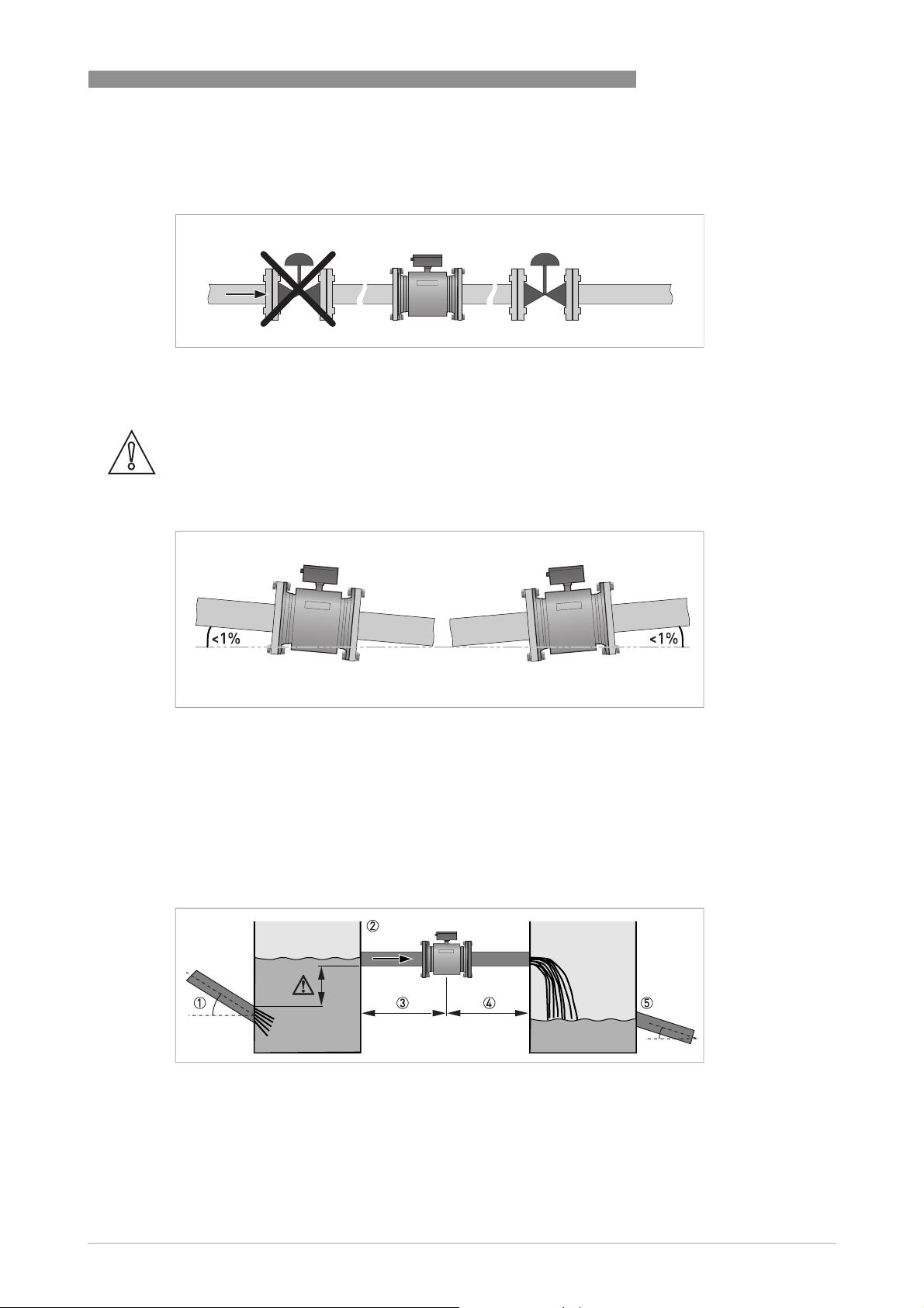
2.3.6 Control valve
Figure 2-8: Installation before control valve
2.3.7 Slope
CAUTION!
The accuracy is influenced by the slope. Stay within
measurements!
INSTALLATION 2
±
1% to get the most accurate
Figure 2-9: Recommended slope
2.3.8 Mounting advice for difficult situations
If you can not meet the installation conditions install the flowmeter between two containers. The
inlet to the flowmeter must be higher than the outlet of the fluid. In this way you will have a calm
flow into the flowmeter, resulting in a highly accurate measurement. The sizes of the containers
must be proportional to the size of the flowmeter.
Figure 2-10: Installing in difficult situations
1 Use a container 2 if the Inlet pipe has a slope > 1%. Make sure that the outlet level of this pipe is below the inlet to the
flowmeter.
2 Inlet container
3 Inlet section of 10 DN
4 Outlet section of 5 DN
5 Outlet container advisable if outlet pipe has a slope > 1%.
www.krohne.com09/2010 - 7308302300 - QS TIDALFLUX 4000 R03 en
7
Page 8
2 INSTALLATION
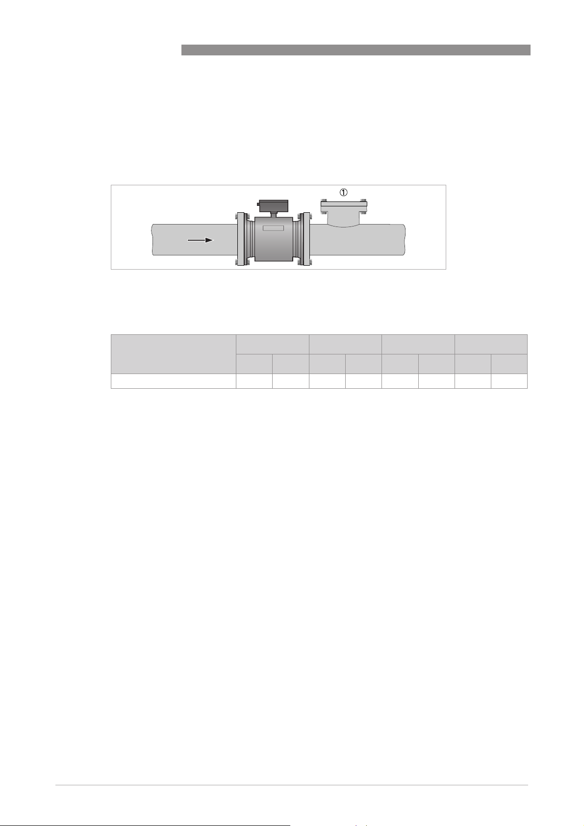
2.3.9 Cleaning of flow sensor
The TIDALFLUX flow sensor is highly resistant against dirt and the measurement will rarely be
influenced by anything. However, it is advisable to create a possiblity for cleaning just before or
after the sensor.
Figure 2-11: Option for cleaning of flow sensor
1 Opening for cleaning
2.3.10 Temperatures
TIDALFLUX 4300 F
Temperature range Process [°C] Ambient [°C] Process [°F] Ambient [°F]
min. max. min. max. min. max. min. max.
All versions -5 60 -25 60 23 140 -13 140
8
www.krohne.com 09/2010 - 7308302300 - QS TIDALFLUX 4000 R03 en
Page 9
TIDALFLUX 4300 F
2.4 Mounting
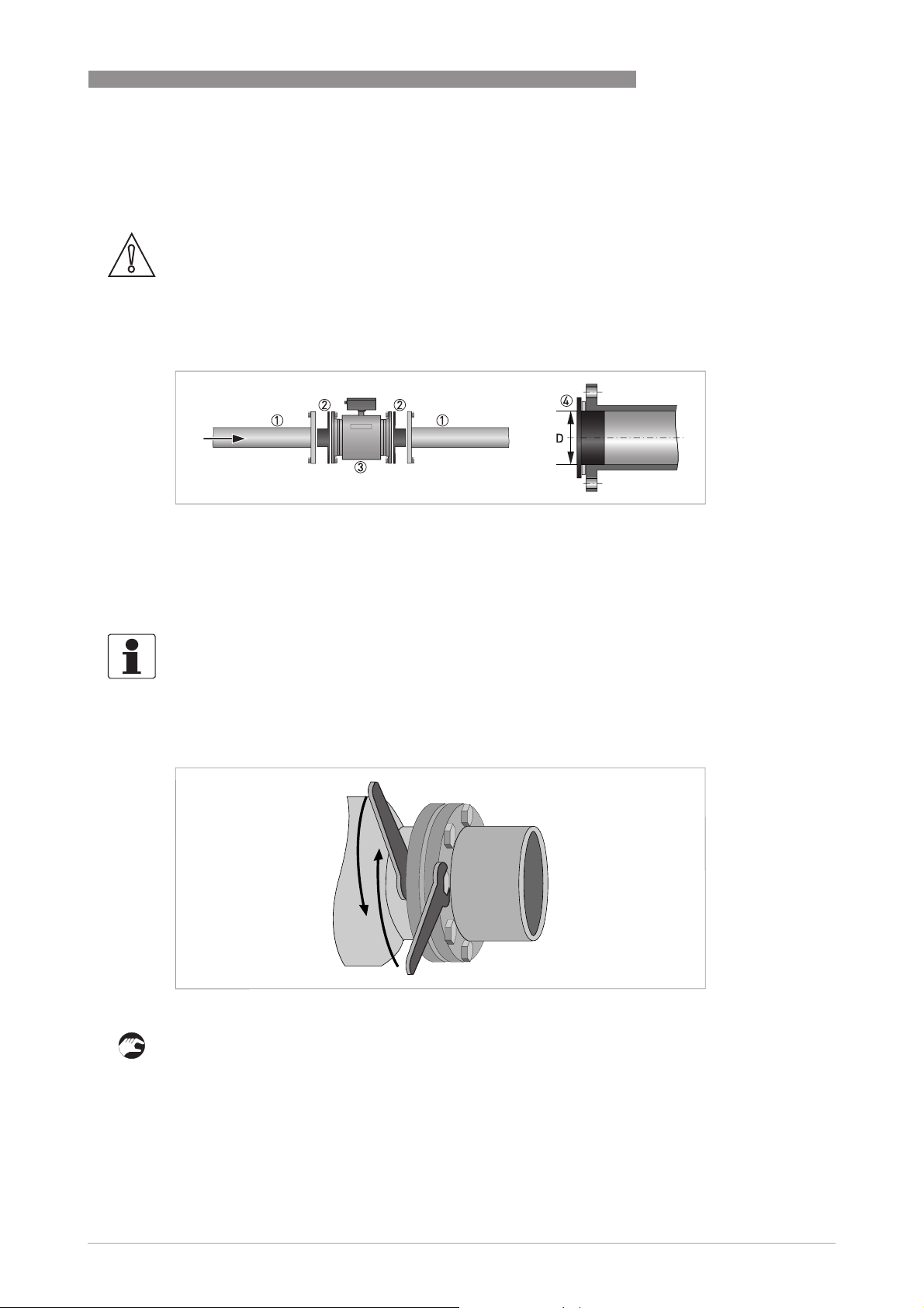
2.4.1 Mounting grounding rings
CAUTION!
In order to get a reliable height measurement it is absolutely necessary
connecting pipeline is electrically conductive and connected to ground. If not, tailor-made
grounding rings with a cylindrical part can be delivered. Please contact your local agency in case
of doubt.
Figure 2-12: Grounding with grounding rings
1 Existing pipeline
2 Grounding rings, custom made to inner diameter of pipeline
3 TIDALFLUX
4 Insert the cylindrical part of the grounding ring into the pipeline. Use an appropiate gasket between the grounding ring
and the flange.
INSTALLATION 2
absolutely necessary that the inner side of the
absolutely necessaryabsolutely necessary
INFORMATION!
Sizes of the grounding rings are diameter dependent and available on request.
2.4.2 Torques and pressures
Figure 2-13: Tightening of bolts
Tightening of bolts
1 Step 1: Apply approx. 50% of max. torque given in table.
2 Step 2: Apply approx. 80% of max. torque given in table.
3 Step 3: Apply 100% of max. torque given in table.
www.krohne.com09/2010 - 7308302300 - QS TIDALFLUX 4000 R03 en
9
Page 10

2 INSTALLATION
INFORMATION!
Tighten the bolts uniformely in diagonally opposite sequence.
TIDALFLUX 4300 F
Nominal size
DN [mm]
Nominal size
[inch]
Pressure
Bolts Max. torque [Nm]
r a t i n g
200 PN 10 8 × M 20 68
250 PN 10 12 × M 20 65
300 PN 10 12 × M 20 76
350 PN 10 16 × M 20 75
400 PN 10 16 × M 24 104
500 PN 10 20 × M 24 107
600 PN 10 20 × M 27 138
700 PN 10 20 × M 27 163
800 PN 10 24 × M 30 219
900 PN 10 28 × M 30 205
1000 PN 10 28 × M 35 261
Flange class
Bolts Max. torque [Nm]
[lb]
8 150 8 × 3/4" 69
10 150 12 × 7/8" 79
12 150 12 × 7/8" 104
14 150 12 × 1" 93
16 150 16 × 1" 91
18 150 16 × 1 1/8" 143
20 150 20 × 1 1/8" 127
24 150 20 × 1 1/4" 180
28 150 28 × 1 1/4" 161
32 150 28 × 1 1/2" 259
36 150 32 × 1 1/2" 269
40 150 36 × 1 1/2" 269
10
INFORMATION!
Information for bigger sizes is available on request.
www.krohne.com 09/2010 - 7308302300 - QS TIDALFLUX 4000 R03 en
Page 11

TIDALFLUX 4300 F
3.1 Safety instructions
DANGER!
All work on the electrical connections may only be carried out with the power disconnected. Take
note of the voltage data on the nameplate!
DANGER!
Observe the national regulations for electrical installations!
WARNING!
Observe without fail the local occupational health and safety regulations. Any work done on the
electrical components of the measuring device may only be carried out by properly trained
specialists.
INFORMATION!
Look at the device nameplate to ensure that the device is delivered according to your order.
Check for the correct supply voltage printed on the nameplate.
ELECTRICAL CONNECTIONS 3
3.2 Important notes on electrical connection
DANGER!
Electrical connection is carried out in conformity with the VDE 0100 directive "Regulations for
electrical power installations with line voltages up to 1000 V" or equivalent national regulations.
CAUTION!
•
Use suitable cable entries for the various electrical cables.
•
The sensor and converter are configured together in the factory. For this reason, please
connect the devices in pairs. Ensure that the sensor constant GK (see type plates) are
identically set
www.krohne.com09/2010 - 7308302300 - QS TIDALFLUX 4000 R03 en
11
Page 12

3 ELECTRICAL CONNECTIONS
3.3 Connection of cables
Figure 3-1: Electrical connection
1 Unscrew the cover to reach the connectors
2 Unscrew the cover to reach the connectors
3 Field current cable
4 Interface cable
5 Signal cable (DS or BTS)
TIDALFLUX 4300 F
Connection diagram
Figure 3-2: Connection diagram
1 Protective Earth connection (PE)
2 Mains power neutral (N)
3 Mains power live (L)
4 Field current cable
5 Interface cable
6 Signal cable. Shown is the BTS cable. In case of DS cable, do not use connectors 20 and 30.
7 Connect housing to PE
12
www.krohne.com 09/2010 - 7308302300 - QS TIDALFLUX 4000 R03 en
Page 13

TIDALFLUX 4300 F
Flow sensors with protection class IP 68 can not be opened anymore. The cables are factory
connected and labeled as follows.
Figure 3-3: Labeled cables for IP 68 versions
1 Mains power (10 = blank, 11 = blue, 12 = black)
2 Field current (7 = white, 8 = green)
3 Data interface (black wires, C = marked "1", D = marked "2", E = marked "3")
4 Electrodes (1 = blank, 2 = white, 3 = red)
ELECTRICAL CONNECTIONS 3
3.4 Cable lengths
CAUTION!
The maximum allowed distance between the flow sensor and the converter is determined by the
shortest cable length.
Interface cable
Interface cable: maximum length is 600 m / 1968 ft.
Interface cableInterface cable
Type B (BTS) signal cable
Type B (BTS) signal cable: maximum length is 600 m / 1968 ft.
Type B (BTS) signal cableType B (BTS) signal cable
Type A (DS) signal cable
Type A (DS) signal cable: maximum length depends on the conductivity of the fluid:
Type A (DS) signal cableType A (DS) signal cable
Electrical conductivity Maximum length
[µS/cm] [m] [ft]
50 120 394
100 200 656
200 400 1312
≥400 600 1968
www.krohne.com09/2010 - 7308302300 - QS TIDALFLUX 4000 R03 en
13
Page 14

3 ELECTRICAL CONNECTIONS
Field current cable
Field current cable: The cross section of the cable determines the maximum length:
Field current cableField current cable
Cross section Maximum length
TIDALFLUX 4300 F
[mm2]
2 x 0.75 2 x 18 150 492
2 x 1.5 2 x 14 300 984
2 x 2.5 2 x 12 600 1968
[AWG] [m] [ft]
14
www.krohne.com 09/2010 - 7308302300 - QS TIDALFLUX 4000 R03 en
Page 15

TIDALFLUX 4300 F
ELECTRICAL CONNECTIONS 3
3.5 Signal cable A (type DS 300), construction
• Signal cable A is a double-shielded cable for signal transmission between the measuring
sensor and signal converter.
• Bending radius: ≥ 50 mm / 2"
Figure 3-4: Construction of signal cable A
2
1 Stranded drain wire (1) for the inner shield (10), 1.0 mm
2 Insulated wire (2), 0.5 mm
3 Insulated wire (3), 0.5 mm
4 Outer sheath
5 Insulation layers
6 Stranded drain wire (6) for the outer shield (60)
2
Cu / AWG 20
2
Cu / AWG 20
Cu / AWG 17 (not insulated, bare)
www.krohne.com09/2010 - 7308302300 - QS TIDALFLUX 4000 R03 en
15
Page 16

3 ELECTRICAL CONNECTIONS
3.6 Preparing signal cable A, connection to measuring sensor
INFORMATION!
Assembly materials and tools are not part of the delivery. Use the assembly materials and tools
in compliance with the applicable occupational health and safety directives.
• The outer shield (60) is connected in the terminal compartment of the measuring sensor
directly via the shield and a clip.
• Bending radius: ≥ 50 mm / 2"
Required materials
• PVC insulating tube, Ø2.0...2.5 mm / 0.08...0.1"
• Heat-shrinkable tubing
• Wire end ferrule to DIN 46 228: E 1.5-8 for the stranded drain wire (1)
• 2 wire end ferrules to DIN 46 228: E 0.5-8 for the insulated conductors (2, 3)
TIDALFLUX 4300 F
16
Figure 3-5: Preparing signal cable A, connection to measuring sensor
a = 50 mm / 2"
b = 10 mm / 0.39"
1 Strip the conductor to dimension a.
2 Trim the outer shield (60) to dimension b and pull it over the outer sheath.
3 Remove the stranded drain wire (6) of the outer shield and the inner shield (10). Make sure not
to damage the stranded drain wire (1) of the inner shield.
4 Slide an insulating tube over the stranded drain wire (1).
5 Crimp the wire end ferrules onto conductors 2 and 3 and the stranded drain wire (1).
6 Pull the heat-shrinkable tubing over the prepared signal cable.
www.krohne.com 09/2010 - 7308302300 - QS TIDALFLUX 4000 R03 en
Page 17

TIDALFLUX 4300 F
ELECTRICAL CONNECTIONS 3
3.7 Signal cable B (type BTS 300), construction
• Signal cable B is a triple-shielded cable for signal transmission between the measuring
sensor and signal converter.
• Bending radius: ≥ 50 mm / 2"
Figure 3-6: Construction of signal cable B
2
1 Stranded drain wire for the inner shield (10), 1.0 mm
2 Insulated wire (2), 0.5 mm
3 Insulated wire (3), 0.5 mm
4 Outer sheath
5 Insulation layers
6 Stranded drain wire (6) for the outer shield (60), 0.5 mm
2
Cu / AWG 20 with stranded drain wire (20) of shield
2
Cu / AWG 20 with stranded drain wire (30) of shield
Cu / AWG 17 (not insulated, bare)
2
Cu / AWG 20 (not insulated, bare)
3.8 Preparing signal cable B, connection to measuring sensor
INFORMATION!
Assembly materials and tools are not part of the delivery. Use the assembly materials and tools
in compliance with the applicable occupational health and safety directives.
• The outer shield (60) is connected in the terminal compartment of the measuring sensor
directly via the shield and a clip.
• Bending radius: ≥ 50 mm / 2"
Required materials
• PVC insulation tubing, Ø2.0...2.5 mm / 0.08...0.1"
• Heat-shrinkable tubing
• Wire end ferrule to DIN 46 228: E 1.5-8 for the stranded drain wire (1)
• 2x wire end ferrules to DIN 46 228: E 0.5-8 for the insulated conductors (2, 3)
www.krohne.com09/2010 - 7308302300 - QS TIDALFLUX 4000 R03 en
17
Page 18

3 ELECTRICAL CONNECTIONS
Figure 3-7: Preparing signal cable B, connection to measuring sensor
a = 50 mm / 2"
b = 10 mm / 0.39"
TIDALFLUX 4300 F
1 Strip the conductor to dimension a.
2 Trim the outer shield (60) to dimension b and pull it over the outer sheath.
3 Remove the stranded drain wire (6) of the outer shield and the shields and stranded drain
wires of the insulated conductors (2, 3). Remove the inner shield (10). Be sure not to damage
the stranded drain wire (1).
4 Slide an insulating tube over the stranded drain wire (1).
5 Crimp the wire end ferrules onto conductors 2 and 3 and the stranded drain wire (1).
6 Pull the heat-shrinkable tubing over the prepared signal cable.
18
www.krohne.com 09/2010 - 7308302300 - QS TIDALFLUX 4000 R03 en
Page 19

TIDALFLUX 4300 F
ELECTRICAL CONNECTIONS 3
3.9 Preparing field current cable C, connection to measuring sensor
INFORMATION!
Assembly materials and tools are not part of the delivery. Use the assembly materials and tools
in compliance with the applicable occupational health and safety directives.
• The field current cable is not part of the scope of delivery.
• The shield is connected in the terminal compartment of the converter directly via the shield
and a clip.
• The shield is connected in the sensor via the special cable gland.
• Bending radius: ≥ 50 mm / 2"
Required materials
• Shielded 2-wire insulated copper cable
• Insulating tube, size according to the cable being used
• Heat-shrinkable tubing
• DIN 46 228 wire end ferrules: size according to the cable being used
Figure 3-8: Preparation of field current cable C
a = 125 mm / 5"
b = 10 mm / 0.4"
1 Strip the conductor to dimension a.
2 Trim the outer shield to dimension b and pull it over the outer sheath.
3 Crimp wire end ferrules onto both conductors.
www.krohne.com09/2010 - 7308302300 - QS TIDALFLUX 4000 R03 en
19
Page 20

3 ELECTRICAL CONNECTIONS
At flow converter side:
Connecting shielding under clamp in connection box of converter
Figure 3-9: Clamping of shields
1 Field current cable
2 Signal cable
At flow sensor side:
Connecting shielding via special cable gland
TIDALFLUX 4300 F
20
Figure 3-10: Connecting the shield within the cable gland
1 Wires
2 Isolation
3 Shielding
4 Isolation
5 Feed cable through dome nut and clamping insert and fold shielding over clamping insert. Make sure that the braided
shield overlaps the O-ring by 2 mm / 3/32".
6 Push clamping insert into body.
7 Tighten the dome nut.
www.krohne.com 09/2010 - 7308302300 - QS TIDALFLUX 4000 R03 en
Page 21

TIDALFLUX 4300 F
3.10 Interface cable
The data interface cable is a shielded, 3 x 1.5 mm2 LIYCY cable. The standard length 10 m /
32.8 ft is included in the delivery.
Preparing the interface cable
Figure 3-11: Preparing the interface cable
a = 100 mm / 4"
b = 10 mm / 0.4"
ELECTRICAL CONNECTIONS 3
1 Strip the conductor to dimension a.
2 Trim the outer shield to dimension b and pull it over the outer sheath.
3 Crimp the wire end ferrules onto the conductors 1, 2 and 3.
Connect the shielding at both sides of the cable via the special cable gland.
Connecting shielding via special cable gland
Figure 3-12: Connecting the shield within the cable gland
1 Wires
2 Isolation
3 Shielding
4 Isolation
5 Feed cable through dome nut and clamping insert and fold shielding over clamping insert. Make sure that the braided
shield overlaps the O-ring by 2 mm / 3/32".
6 Push clamping insert into body.
7 Tighten the dome nut.
www.krohne.com09/2010 - 7308302300 - QS TIDALFLUX 4000 R03 en
21
Page 22

3 ELECTRICAL CONNECTIONS
3.11 Grounding
DANGER!
The device must be grounded in accordance with regulations in order to protect personnel
against electric shocks.
CAUTION!
In order to get a reliable height measurement it is absolutely necessary
connecting pipeline is electrically conductive and connected to ground. If not, tailor-made
grounding rings with a cylindrical part can be delivered. Please contact your local agency in case
of doubt.
TIDALFLUX 4300 F
absolutely necessary that the inner side of the
absolutely necessaryabsolutely necessary
Figure 3-13: Grounding ring number 3
22
www.krohne.com 09/2010 - 7308302300 - QS TIDALFLUX 4000 R03 en
Page 23

TIDALFLUX 4300 F
4.1 Switching on the power
Before connecting to power, please check that the system has been correctly installed.
This includes:
• The device must be mechanically mounted safely in compliance with the regulations.
• The power connections must be in compliance with the regulations.
• Make sure that all electrical connections are made and that the covers of the terminal
compartments are closed.
• Check that the electrical operating data of the power supply are correct.
• Switch on the power.
INFORMATION!
The sensor can not be programmed or changed in any way. All settable functions are included in
the converter. Please see the relevant documentation of the converter for more information.
START-UP 4
www.krohne.com09/2010 - 7308302300 - QS TIDALFLUX 4000 R03 en
23
Page 24

5 TECHNICAL DATA
5.1 Dimensions and weights
The inner pipe diameter should match the inner diameter of the flowmeter. Since the inner
diameter is not a standard DN size, choose the inner pipe diameter to be just a little bit bigger
than the flow meter diameter. If a lot of sediment or fat is expected the optimal solution is to
produce a diameter compensation ring on both sides to have smooth transits.
TIDALFLUX 4300 F
IP 67 versions:
IP 67 versions:
IP 67 versions:IP 67 versions:
k = 232 mm / 9.1"
m = 110 mm / 4.3"
n = 202 mm / 7.95"
IP 68 versions:
IP 68 versions:
IP 68 versions:IP 68 versions:
k = 344 mm / 13.54"
m = 155 mm / 6.1"
n = 284 mm / 11.18"
EN 1092-1
Nominal size Dimensions [mm] Approx.
DN PN a b Øc d j ØD ØD
IP 67 IP 68
200 10 350 473 532 291 146 177 340 189 40
250 10 400 521 579 331 166 205 395 231 54
300 10 500 571 629 381 191 235 445 281 66
350 10 500 623 682 428 214 306 505 316 95
400 10 600 681 739 483 242 386 565 365 115
500 10 600 784 843 585 293 386 670 467 145
600 10 600 894 952 694 347 386 780 567 180
700 10 700 1010 1069 812 406 455 895 666 265
800 10 800 1125 1184 922 461 535 1015 768 350
900 10 900 1246 1305 1064 532 625 1115 863 425
1000 10 1000 1338 1396 1132 566 695 1230 965 520
1200 6 1200 1529 1588 1340 670 854 1405 1169 659
1400 6 1400 1732 1791 1521 761 1034 1630 1367 835
1600 6 1600 1932 1991 1721 861 1234 1830 1549 1659
weight
i
[kg]
24
www.krohne.com 09/2010 - 7308302300 - QS TIDALFLUX 4000 R03 en
Page 25

TIDALFLUX 4300 F
150 lb flanges
Nominal size Dimensions [inches] Approx.
ASME 1PN
1 Nominal size ≤ 24": ASME; > 24": AWWA
TECHNICAL DATA 5
a b Øc d j ØD ØD
[psi]
IP 67 IP 68
8 284 13.78 19.02 20.9 11.46 5.75 6.97 13.39 7.44 90
10 284 15.75 21.06 22.8 13.03 6.54 8.07 15.55 9.09 120
12 284 19.69 23.54 24.8 15 7.52 9.25 17.52 11.06 145
14 284 27.56 25.43 26.8 16.85 9.8 12.05 19.88 12.44 210
16 284 31.5 27.72 29.1 19.02 9.53 15.2 22.24 14.37 255
20 284 31.5 31.73 33.2 23.03 11.54 15.2 26.38 18.39 320
24 284 31.5 36.14 37.5 27.32 13.66 15.2 30.71 22.32 400
28 Class D 35.43 40.4 42.7 31.97 15.98 17.87 36.50 26.22 692
32 Class D 39.37 45.2 47.5 36.3 18.15 21.06 41.75 30.24 1031
36 Class D 43.31 50.1 52.4 41.89 20.94 24.61 46.0 33.98 1267
40 Class D 47.24 53.8 56.1 44.57 22.28 27.36 50.75 37.99 1554
48 Class D 55.12 62.3 64.6 52.76 26.38 33.62 59.50 46.02 2242
i
weight
[lb]
5.2 Vacuum load
Diameter Vacuum load in mbar abs. at a process temperature of
[mm] 40°C 60°C
DN200...1600 500 600
Diameter Vacuum load in psia at a process temperature of
[inches] 104°F 140°F
8...64" 7.3 8.7
www.krohne.com09/2010 - 7308302300 - QS TIDALFLUX 4000 R03 en
25
Page 26

6 NOTES
TIDALFLUX 4300 F
26
www.krohne.com 09/2010 - 7308302300 - QS TIDALFLUX 4000 R03 en
Page 27

TIDALFLUX 4300 F
NOTES 6
www.krohne.com09/2010 - 7308302300 - QS TIDALFLUX 4000 R03 en
27
Page 28

KROHNE product overview
• Electromagnetic flowmeters
• Variable area flowmeters
• Ultrasonic flowmeters
• Mass flowmeters
• Vortex flowmeters
• Flow controllers
• Level meters
• Temperature meters
• Pressure meters
• Analysis products
• Measuring systems for the oil and gas industry
• Measuring systems for sea-going tankers
Head Office KROHNE Messtechnik GmbH
Ludwig-Krohne-Str. 5
D-47058 Duisburg (Germany)
Tel.:+49 (0)203 301 0
Fax:+49 (0)203 301 10389
info@krohne.de
The current list of all KROHNE contacts and addresses can be found at:
© KROHNE 09/2010 - 7308302300 - QS TIDALFLUX 4000 R03 en - Subject to change without notice.
www.krohne.com
 Loading...