

Page 1
Handbook
Handbook
OPTIWAVE 7500 C
OPTIWAVE 7500 C
OPTIWAVE 7500 COPTIWAVE 7500 C
Radar (FMCW) Level Transmitter for high-precision
storage of liquids
HandbookHandbook
© KROHNE 10/2016 - 4004375401 - MA OPTIWAVE 7500 R01 en
Page 2

:
IMPRINT
:::::::::::::::::::::::::::::::::::::::
All rights reserved. It is prohibited to reproduce this documentation, or any part thereof, without
the prior written authorisation of KROHNE Messtechnik GmbH.
Subject to change without notice.
Copyright 2016 by
KROHNE Messtechnik GmbH - Ludwig-Krohne-Str. 5 - 47058 Duisburg (Germany)
2
www.krohne.com 10/2016 - 4004375401 - MA OPTIWAVE 7500 R01 en
Page 3

OPTIWAVE 7500 C
CONTENTS
1 Safety instructions 7
1.1 Software history ............................................................................................................... 7
1.2 Intended use ..................................................................................................................... 7
1.3 Certification ...................................................................................................................... 8
1.4 Electromagnetic compatibility ......................................................................................... 8
1.5 Radio approvals ................................................................................................................ 9
1.5.1 European Union (EU)............................................................................................................... 9
1.5.2 U.S.A...................................................................................................................................... 11
1.5.3 Canada................................................................................................................................... 13
1.6 Safety instructions from the manufacturer................................................................... 15
1.6.1 Copyright and data protection .............................................................................................. 15
1.6.2 Disclaimer ............................................................................................................................. 15
1.6.3 Product liability and warranty .............................................................................................. 16
1.6.4 Information concerning the documentation......................................................................... 16
1.6.5 Warnings and symbols used................................................................................................. 17
1.7 Safety instructions for the operator............................................................................... 17
2 Device description 18
2.1 Scope of delivery............................................................................................................. 18
2.2 Device description .......................................................................................................... 19
2.3 Visual Check ................................................................................................................... 20
2.4 Nameplates .................................................................................................................... 21
2.4.1 Nameplate (examples).......................................................................................................... 21
3 Installation 22
3.1 General notes on installation ......................................................................................... 22
3.2 Storage ........................................................................................................................... 22
3.3 Transport ........................................................................................................................ 22
3.4 Pre-installation requirements ....................................................................................... 22
3.5 Pressure and temperature ranges ................................................................................ 23
3.6 Recommended mounting position ................................................................................. 24
3.6.1 General notes........................................................................................................................ 24
3.6.2 Tanks with conical bottoms .................................................................................................. 24
3.7 Mounting restrictions ..................................................................................................... 24
3.7.1 General data for TLPR devices ............................................................................................. 25
3.7.2 Obstacles in the tank ............................................................................................................ 25
3.7.3 Process connections............................................................................................................. 26
3.8 How to turn or remove the display module (option) ...................................................... 27
3.9 How to turn or remove the signal converter.................................................................. 28
3.10 Weather protection....................................................................................................... 29
3.10.1 How to attach the weather protection to the device........................................................... 29
3.10.2 How to open the weather protection .................................................................................. 31
4 Electrical connections 32
4.1 Safety instructions.......................................................................................................... 32
4.2 Electrical installation: 2-wire, loop-powered ................................................................ 32
www.krohne.com10/2016 - 4004375401 - MA OPTIWAVE 7500 R01 en
3
Page 4

CONTENTS
OPTIWAVE 7500 C
4.3 Electrical connection for current output ....................................................................... 36
4.3.1 Non-Ex devices ..................................................................................................................... 36
4.3.2 Devices for hazardous locations........................................................................................... 36
4.4 Protection category ........................................................................................................36
4.5 Networks ........................................................................................................................ 37
4.5.1 General information.............................................................................................................. 37
4.5.2 Point-to-point connection..................................................................................................... 37
4.5.3 Multi-drop networks ............................................................................................................. 38
5 Start-up 39
5.1 Start-up checklist........................................................................................................... 39
5.2 How to start the device................................................................................................... 39
5.3 Operating concept ..........................................................................................................39
5.4 Digital display screen .....................................................................................................40
5.4.1 Display screen layout............................................................................................................ 40
5.4.2 Keypad buttons ..................................................................................................................... 41
5.5 Remote communication with PACTware™ .................................................................... 43
5.6 Remote communication with the AMS™ Device Manager............................................. 44
6 Operation 45
6.1 User modes .................................................................................................................... 45
6.2 Normal mode.................................................................................................................. 45
6.3 Program mode................................................................................................................ 47
6.3.1 General notes........................................................................................................................ 47
6.3.2 Protection of the device settings (security levels) ............................................................... 47
6.3.3 How to get access to the Quick Setup menu ........................................................................ 49
6.3.4 Keypad functions................................................................................................................... 50
6.3.5 How to save settings changed in program mode ................................................................. 53
6.3.6 Menu overview ...................................................................................................................... 54
6.3.7 Function description ............................................................................................................. 60
6.4 Further information on device configuration in program mode ................................... 79
6.4.1 Standard Setup ..................................................................................................................... 79
6.4.2 Empty spectrum recording................................................................................................... 82
6.4.3 HART® network configuration ............................................................................................. 84
6.4.4 Distance measurement ........................................................................................................ 85
6.4.5 Level measurement .............................................................................................................. 85
6.4.6 How to configure the device to measure volume or mass................................................... 86
6.4.7 How to make a filter to remove radar signal interference .................................................. 87
6.4.8 ............................................................................................................................................... 87
6.5 Status messages and diagnostic data............................................................................ 88
7 Service 94
7.1 Periodic maintenance..................................................................................................... 94
7.1.1 General notes........................................................................................................................ 94
7.1.2 Maintainance of the O-rings for the housing covers ............................................................ 94
7.1.3 How to clean the top surface of the device........................................................................... 95
7.1.4 How to clean horn antennas under process conditions....................................................... 95
7.2 Service warranty............................................................................................................. 95
4
www.krohne.com 10/2016 - 4004375401 - MA OPTIWAVE 7500 R01 en
Page 5

OPTIWAVE 7500 C
CONTENTS
7.3 Spare parts availability...................................................................................................95
7.4 Availability of services .................................................................................................... 95
7.5 Returning the device to the manufacturer..................................................................... 96
7.5.1 General information.............................................................................................................. 96
7.5.2 Form (for copying) to accompany a returned device............................................................ 97
7.6 Disposal .......................................................................................................................... 97
8 Technical data 98
8.1 Measuring principle........................................................................................................98
8.2 Technical data................................................................................................................. 99
8.3 Minimum power supply voltage ................................................................................... 103
8.4 Guidelines for maximum operating pressure.............................................................. 104
8.5 Dimensions and weights .............................................................................................. 105
9 Description of HART interface 107
9.1 General description ...................................................................................................... 107
9.2 Software history ...........................................................................................................107
9.3 Connection variants...................................................................................................... 108
9.3.1 Point-to-Point connection – analogue / digital mode ........................................................ 108
9.3.2 Multi-Drop connection (2-wire connection) ....................................................................... 108
9.4 HART® device variables............................................................................................... 108
9.5 Field Communicator 475 (FC 475)................................................................................ 109
9.5.1 Installation .......................................................................................................................... 109
9.5.2 Operation............................................................................................................................. 109
9.6 Asset Management Solutions (AMS®) ......................................................................... 109
9.6.1 Installation .......................................................................................................................... 109
9.6.2 Operation............................................................................................................................. 110
9.6.3 Parameter for the basic configuration ............................................................................... 110
9.7 Field Device Tool / Device Type Manager (FDT / DTM)................................................ 110
9.7.1 Installation .......................................................................................................................... 110
9.7.2 Operation............................................................................................................................. 110
9.8 Process Device Manager (PDM)................................................................................... 110
9.8.1 Installation .......................................................................................................................... 110
9.8.2 Operation............................................................................................................................. 111
9.9 HART® menu tree for AMS .......................................................................................... 111
9.9.1 Overview AMS menu tree (positions in menu tree)............................................................ 111
9.9.2 AMS menu tree (details for settings).................................................................................. 111
9.10 HART® menu tree for PDM........................................................................................ 111
9.10.1 Overview PDM menu tree (positions in menu tree).......................................................... 111
9.10.2 PDM menu tree (details for settings) ............................................................................... 112
10 Appendix 116
10.1 Order code .................................................................................................................. 116
10.2 Spare parts ................................................................................................................. 116
10.3 Accessories................................................................................................................. 120
10.4 Glossary ...................................................................................................................... 121
www.krohne.com10/2016 - 4004375401 - MA OPTIWAVE 7500 R01 en
5
Page 6

CONTENTS
OPTIWAVE 7500 C
11 Notes 123
6
www.krohne.com 10/2016 - 4004375401 - MA OPTIWAVE 7500 R01 en
Page 7

OPTIWAVE 7500 C
1.1 Software history
"Firmware revision" agrees with NAMUR NE 53. It is a series of numbers used to record the
revision status of embedded software (firmware) in electronic equipment assemblies. It gives
data on the type of changes made and the effect that changes have on compatibility.
SAFETY INSTRUCTIONS
1
Data about software revisions is shown in menu 1.1.0 IDENT. For more data, refer to
description
of the device (given on the device nameplate) and speak to the supplier.
Release
date
YYYY-MM-DDConverter 1.00.0x 400xxxxx01 — HB OPTIWAVE
Printed circuit
assembly
Sensor 1.00.0x 400xxxxx01
HMI (LCD display
option)
on page 60. If it is not possible to refer to the device menu, record the serial number
Firmware
revision
1.00.0x 400xxxxx01
Hardware
revision
Changes and
compatibility
Documentation
7500 R01
Function
1.2 Intended use
CAUTION!
Responsibility for the use of the measuring devices with regard to suitability, intended use and
corrosion resistance of the used materials against the measured fluid lies solely with the
operator.
INFORMATION!
The manufacturer is not liable for any damage resulting from improper use or use for other than
the intended purpose.
CAUTION!
SIL-qualified devices:
SIL-qualified devices:
SIL-qualified devices:SIL-qualified devices:
For more data, refer to the Safety Manual.
This radar level transmitter measures distance, level, mass, volume and reflectivity of liquids,
pastes and slurries.
It can be installed on tanks, reactors and open channels.
www.krohne.com10/2016 - 4004375401 - MA OPTIWAVE 7500 R01 en
7
Page 8

1
SAFETY INSTRUCTIONS
1.3 Certification
DANGER!
For devices used in hazardous areas, additional safety notes apply; please refer to the Ex
documentation.
INFORMATION!
For SIL-approved devices; please refer to the safety manual.
CE marking
The device meets the essential requirements of the EU Directives:
• Electromagnetic Compatibility (EMC) directive
• The safety part of the Low-Voltage directive
• For devices used in hazardous locations: ATEX directive
OPTIWAVE 7500 C
The manufacturer certifies successful testing of the product by applying the CE marking. For
more data about the EU Directives and European Standards related to this device, refer to the EU
Declaration of Conformity. You can find this documentation on the DVD-ROM supplied with the
device or it can be downloaded free of charge from the website (Download Center).
All devices are based on the CE marking and meet the requirements of NAMUR
Recommendations NE 21, NE 43, NE 53 and NE 107.
1.4 Electromagnetic compatibility
The device agrees with Electromagnetic Compatibility Directive.
You can install the device on tanks, open vessels or channels, but the type of antenna must agree
with the location of the device. For more data, refer to
INFORMATION!
This agrees with Immunity and Emissions requirements for industrial environments.
Radio approvals
on page 9.
8
www.krohne.com 10/2016 - 4004375401 - MA OPTIWAVE 7500 R01 en
Page 9
OPTIWAVE 7500 C
1.5 Radio approvals
1.5.1 European Union (EU)
INFORMATION!
LPR (Level Probing Radar)
LPR (Level Probing Radar) equipment are devices for the measurement of level in the open air
LPR (Level Probing Radar)LPR (Level Probing Radar)
or in a closed space (a metallic tank etc.). TLPR (Tank Level Probing Radar)
devices for the measurement of level in a closed space only. You can use LPR devices for TLPR
applications. The LPR and TLPR devices meet the requirements of the RED (Radio Equipment
Directive) for use in the member countries of the EU.
SAFETY INSTRUCTIONS
TLPR (Tank Level Probing Radar) equipment are
TLPR (Tank Level Probing Radar)TLPR (Tank Level Probing Radar)
1
For more data about the order code, refer to Order code on page 116
.
This level transmitter is approved to be used outside metallic tanks. If you use the device
outdoors, read the device nameplate to make sure that the device can be used for your
application. Refer also to the table that follows:
Antenna type Order code Permitted for:
PEEK / Lens Ø20 mm / ¾¨ VFDFxxxxxxxxxxxxx1xx... TLPR
PEEK / Lens Ø25 mm / 1¨ VFDFxxxxxxxxxxxxx2xx... TLPR
PEEK / Lens Ø40 mm / 1.57¨ VFDFxxxxxxxxxxxxx3xx... LPR
PEEK / Lens Ø70 mm / 2.75¨ VFDFxxxxxxxxxxxxx4xx... LPR
S/N: xxxxxxxxxxxxxxxxxxx
Manufacturing date: YYYY-MM-DD
Tag No:
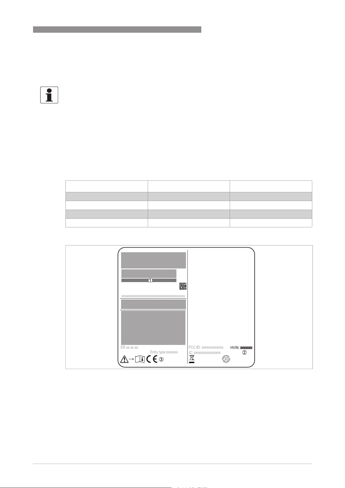
Figure 1-1: Radio approval information on the nameplate
1 Type code (defined in order)
2 HVIN (Hardware Version Identification Number). This number gives the radar signal frequency (80G = 80 GHz), the lo-
cation of the device (T=TLPR or L=LPR) and the type of signal converter (compact (C))
TLPR device: HVIN: 80G-T-C
LPR device: HVIN: 80G-L-C
3 CE sign
www.krohne.com10/2016 - 4004375401 - MA OPTIWAVE 7500 R01 en
9
Page 10

1
SAFETY INSTRUCTIONS
TLPR (Tank Level Probing Radar) devices only
Use approved personnel to install the device. The device and the tank agree with the RED (Radio
Equipment Directive) if you obey the instructions that follow:
• TLPR (Tank Level Probing Radar) are required to be installed at a permanent fixed position at
a closed (not open) metallic tank or reinforced concrete tank, or similar enclosure structure
made of comparable attenuating material;
• flanges and attachments of the TLPR equipment shall provide the necessary microwave
sealing by design;
• sight glasses shall be coated with a microwave-proof coating when necessary (i.e. electrically
conductive coating);
• manholes or connection flanges at the tank shall be closed to ensure a low-level leakage of
the signal into the air outside the tank;
• whenever possible, mounting of the TLPR equipment shall be on top of the tank structure
with the orientation of the antenna to point in a downward direction;
• installation and maintenance of the TLPR equipment shall be performed by professionally
trained individuals only.
OPTIWAVE 7500 C
For data about how to install EMI/RFI shielding gaskets, refer to the instructions supplied with
this accessory.
LPR (Level Probing Radar) devices only
Use approved personnel to install the device. If the device is operated in the open air (outdoors),
it agrees with the RED (Radio Equipment Directive) if you obey these instructions:
• The antenna must always point downwards. The boresight direction of the antenna must be
vertical. No other angles are permitted.
• Install the device more than 4 km / 2.485 mi away from radio astronomy sites.
• If the device is 4...40 km / 2.485...24.855 mi away from radio astronomy sites, do not install the
device more than 15 m / 49.21 ft above the ground.
CAUTION!
If it is necessary to install the device less than 4 km / 2.485 mi from radio astronomy sites, you
must get the approval of the national regulatory authority before installation (e.g. ANFR
(France), Bundesnetzagentur (Germany), Ofcom (United Kingdom) etc.).
Radio quiet zones: locations of radio astronomy sites (stations) in Europe and northern Eurasia
Country Name of the station Location
Latitude, ϕ Longitude, λ
Finland Metsähovi 60°13'04" N 24°23'37" E
France Plateau de Bure 44°38'01" N 05°54'26" E
Germany Effelsberg 50°31'32" N 06°53'00" E
Italy Sardinia 39°29'50" N 09°14'40" E
Spain Yebes 40°31'27" N 03°05'22" W
Pico Veleta 37°03'58" N 03°23'34" W
Sweden Onsala 57°23’45" N 11°55’35" E
10
www.krohne.com 10/2016 - 4004375401 - MA OPTIWAVE 7500 R01 en
Page 11
OPTIWAVE 7500 C
1.5.2 U.S.A.
INFORMATION!
LPR (Level Probing Radar)
LPR (Level Probing Radar) equipment are devices for the measurement of level in the open air
LPR (Level Probing Radar)LPR (Level Probing Radar)
or in a closed space (a metallic tank etc.). TLPR (Tank Level Probing Radar)
devices for the measurement of level in a closed space only.
This level transmitter is approved to be used outside metallic tanks. If you use the device in the
open air, read the device nameplate to make sure that the device can be used for your
application:
PEEK / Lens Ø40 mm / 1.5¨ VFDFxxxxxxxxxxxxx3xx... LPR + TLPR
PEEK / Lens Ø70 mm / 2.75¨ VFDFxxxxxxxxxxxxx4xx... LPR + TLPR
LEGAL NOTICE!
This device complies with Part 15 of the FCC Rules. Operation is subject to the following two
conditions:
1. This device may not cause harmful interference, and
2. This device must accept any interference received, including interference which may cause un-
desired operation.
Changes or modifications made to this equipment not expressly approved by the manufacturer
may void the FCC authorizations to operate this equipment.
SAFETY INSTRUCTIONS
TLPR (Tank Level Probing Radar) equipment are
TLPR (Tank Level Probing Radar)TLPR (Tank Level Probing Radar)
Antenna type Order code Permitted for:
1
This equipment has been tested and found to comply with the limits for a Class B digital device,
pursuant to Part 15 of the FCC Rules. These limits are designed to provide reasonable protection
against harmful interference in a residential installation. This equipment generates, uses and
can radiate radio frequency energy and, if not installed and used in accordance with the
instructions, may cause harmful interference to radio communications. However, there is no
guarantee that interference will not occur in a particular installation. If this equipment does
cause harmful interference to radio or television reception, which can be determined by turning
the equipment off and on, the user is encouraged to try to correct the interference by one or
more of the following measures:
•
Reorient or relocate the receiving antenna.
•
Increase the separation between the equipment and receiver.
•
Connect the equipment into an outlet on a circuit different from that to which the receiver is
connected.
•
Consult the dealer or an experienced radio/TV technician for help.
The Product Marketing Name (PMN) of this device is "Optiwave x500 series".
This level transmitter is approved to be used outside metallic tanks. If you use the device in the
open air, read the device nameplate to make sure that the device can be used for your
application. Only the antenna that follows is permitted for open-air applications:
• VFDFxxxxxxxxxxxxx3xx...
• VFDFxxxxxxxxxxxxx4xx...
www.krohne.com10/2016 - 4004375401 - MA OPTIWAVE 7500 R01 en
11
Page 12
1
SAFETY INSTRUCTIONS
S/N: xxxxxxxxxxxxxxxxxxx
Manufacturing date: YYYY-MM-DD
Tag No:
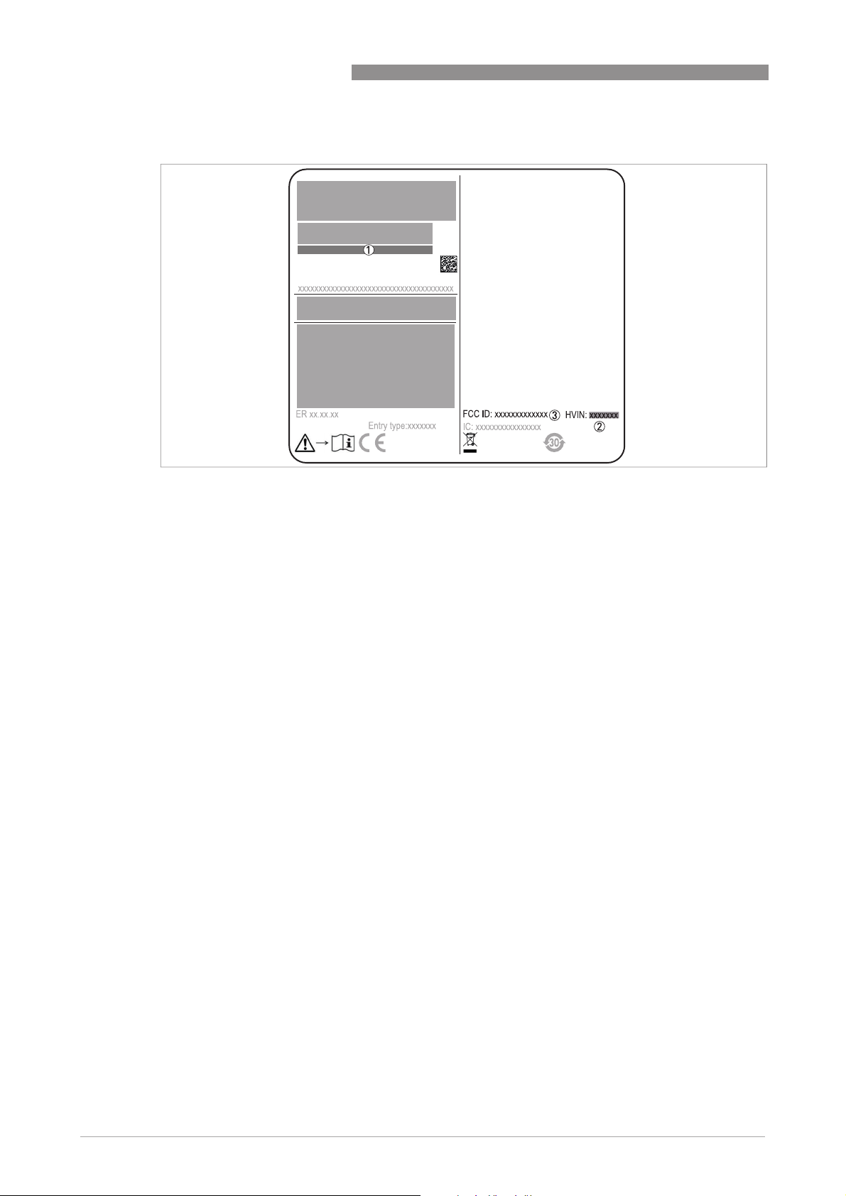
Figure 1-2: FCC ID
1 Type code (defined in order)
2 HVIN (Hardware Version Identification Number). This number gives the radar signal frequency (80G = 80 GHz), the lo-
cation of the device (T=TLPR or L=LPR) and the type of signal converter (compact (C))
TLPR device: HVIN: 80G-T-C
LPR device: HVIN: 80G-L-C
3 FCC ID
TLPR device: FCC-ID: Q6BFMCW80G74T-A
LPR device: FCC-ID: Q6BFMCW80G74L-A
OPTIWAVE 7500 C
12
www.krohne.com 10/2016 - 4004375401 - MA OPTIWAVE 7500 R01 en
Page 13

OPTIWAVE 7500 C
1.5.3 Canada
INFORMATION!
LPR (Level Probing Radar)
LPR (Level Probing Radar) equipment are devices for the measurement of level in the open air
LPR (Level Probing Radar)LPR (Level Probing Radar)
or in a closed space (a metallic tank etc.). TLPR (Tank Level Probing Radar)
devices for the measurement of level in a closed space only.
This level transmitter is approved to be used outside metallic tanks. If you use the device in the
open air, read the device nameplate to make sure that the device can be used for your
application:
PEEK / Lens Ø20 mm / ¾¨ VFDFxxxxxxxxxxxxx1xx... TLPR
PEEK / Lens Ø25 mm / 1¨ VFDFxxxxxxxxxxxxx2xx... TLPR
PEEK / Lens Ø40 mm / 1.57¨ VFDFxxxxxxxxxxxxx3xx... LPR
PEEK / Lens Ø70 mm / 2.75¨ VFDFxxxxxxxxxxxxx4xx... LPR
LEGAL NOTICE!
This device complies with Industry Canada licence-exempt RSS standard(s).
Operation is subject to the following conditions:
1. this device may not cause harmful interference, and
2. this device must accept any interference received, including interference that may cause un-
desired operation.
SAFETY INSTRUCTIONS
TLPR (Tank Level Probing Radar) equipment are
TLPR (Tank Level Probing Radar)TLPR (Tank Level Probing Radar)
Antenna type Order code Permitted for:
1
This device and the handbook complies with the requirements of RSS-Gen. Operation is subject
to the conditions that follow:
1. The installation of the LPR/TLPR device shall be done by trained installers, in strict compliance
with the manufacturer
’
s instructions.
2. The use of this device is on a "no-interference, no-protection" basis. That is, the user shall ac-
cept operations of high-powered radar in the same frequency band which may interfere with or
damage this device. However, devices found to interfere with primary licensing operations will
be required to be removed at the user
’
s expense.
3. The TLPR device shall be installed and operated in a completely enclosed container to prevent
RF emissions, which can otherwise interfere with aeronautical navigation.
4. LPR devices: Ensure a vertically downward orientation of the transmit antenna and a installa-
tion only at fixed locations.
5. The installer / user of this device shall ensure that it is at least 10 km from the Dominion Radio
Astrophysical Observatory (DRAO) near Penticton, British Columbia. The coordinates of the
DRAO are latitude 49
°
19'15" N and longitude 119°37'12" W. For devices not meeting this 10 km
separation (e.g. those in the Okanagan Valley, British Columbia) the installer / user must coordinate with, and obtain the written concurrence of, the Director of the DRAO before the equipment can be installed or operated. The Director of the DRAO may be contacted at 250-497-2300
(tel.) or 250-497-2355 (fax). Alternatively, the Manager, Regulatory Standards, Industry Canada,
may be contacted.
The Product Marketing Name (PMN) of this device is "Optiwave x500 series".
This level transmitter is approved to be used outside metallic tanks. If you use the device in the
open air, read the device nameplate to make sure that the device can be used for your
application. Only the antenna that follows is permitted for open-air applications:
www.krohne.com10/2016 - 4004375401 - MA OPTIWAVE 7500 R01 en
13
Page 14
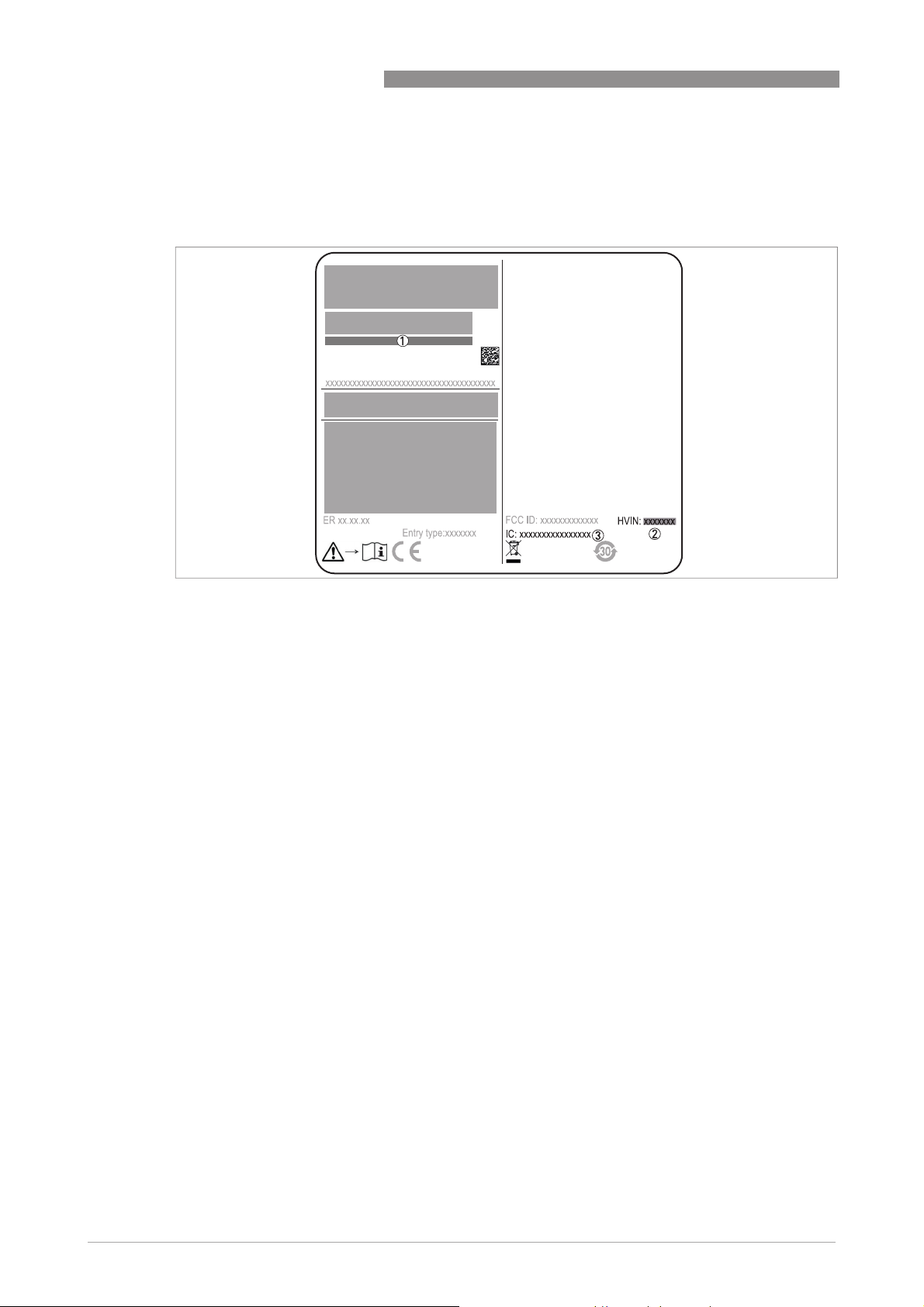
1
SAFETY INSTRUCTIONS
• VFDFxxxxxxxxxxxxx3xx...
• VFDFxxxxxxxxxxxxx4xx...
S/N: xxxxxxxxxxxxxxxxxxx
Manufacturing date: YYYY-MM-DD
Tag No:
OPTIWAVE 7500 C
Figure 1-3: IC number
1 Type code (defined in order)
2 HVIN (Hardware Version Identification Number). This number gives the radar signal frequency (80G = 80 GHz), the lo-
cation of the device (T=TLPR or L=LPR) and the type of signal converter (compact (C))
TLPR device: HVIN: 80G-T-C
LPR device: HVIN: 80G-L-C
3 IC number
TLPR device: 1991D-FMCW80G74T-A
LPR device: 1991D-FMCW80G74L-A
14
www.krohne.com 10/2016 - 4004375401 - MA OPTIWAVE 7500 R01 en
Page 15

OPTIWAVE 7500 C
1.6 Safety instructions from the manufacturer
1.6.1 Copyright and data protection
The contents of this document have been created with great care. Nevertheless, we provide no
guarantee that the contents are correct, complete or up-to-date.
The contents and works in this document are subject to copyright. Contributions from third
parties are identified as such. Reproduction, processing, dissemination and any type of use
beyond what is permitted under copyright requires written authorisation from the respective
author and/or the manufacturer.
The manufacturer tries always to observe the copyrights of others, and to draw on works created
in-house or works in the public domain.
The collection of personal data (such as names, street addresses or e-mail addresses) in the
manufacturer's documents is always on a voluntary basis whenever possible. Whenever
feasible, it is always possible to make use of the offerings and services without providing any
personal data.
SAFETY INSTRUCTIONS
1
We draw your attention to the fact that data transmission over the Internet (e.g. when
communicating by e-mail) may involve gaps in security. It is not possible to protect such data
completely against access by third parties.
We hereby expressly prohibit the use of the contact data published as part of our duty to publish
an imprint for the purpose of sending us any advertising or informational materials that we have
not expressly requested.
1.6.2 Disclaimer
The manufacturer will not be liable for any damage of any kind by using its product, including,
but not limited to direct, indirect or incidental and consequential damages.
This disclaimer does not apply in case the manufacturer has acted on purpose or with gross
negligence. In the event any applicable law does not allow such limitations on implied warranties
or the exclusion of limitation of certain damages, you may, if such law applies to you, not be
subject to some or all of the above disclaimer, exclusions or limitations.
Any product purchased from the manufacturer is warranted in accordance with the relevant
product documentation and our Terms and Conditions of Sale.
The manufacturer reserves the right to alter the content of its documents, including this
disclaimer in any way, at any time, for any reason, without prior notification, and will not be liable
in any way for possible consequences of such changes.
www.krohne.com10/2016 - 4004375401 - MA OPTIWAVE 7500 R01 en
15
Page 16

1
SAFETY INSTRUCTIONS
1.6.3 Product liability and warranty
The operator shall bear responsibility for the suitability of the device for the specific purpose.
The manufacturer accepts no liability for the consequences of misuse by the operator. Improper
installation or operation of the devices (systems) will cause the warranty to be void. The
respective "Standard Terms and Conditions" which form the basis for the sales contract shall
also apply.
1.6.4 Information concerning the documentation
To prevent any injury to the user or damage to the device it is essential that you read the
information in this document and observe applicable national standards, safety requirements
and accident prevention regulations.
If this document is not in your native language and if you have any problems understanding the
text, we advise you to contact your local office for assistance. The manufacturer can not accept
responsibility for any damage or injury caused by misunderstanding of the information in this
document.
This document is provided to help you establish operating conditions, which will permit safe and
efficient use of this device. Special considerations and precautions are also described in the
document, which appear in the form of icons as shown below.
OPTIWAVE 7500 C
16
www.krohne.com 10/2016 - 4004375401 - MA OPTIWAVE 7500 R01 en
Page 17
OPTIWAVE 7500 C
1.6.5 Warnings and symbols used
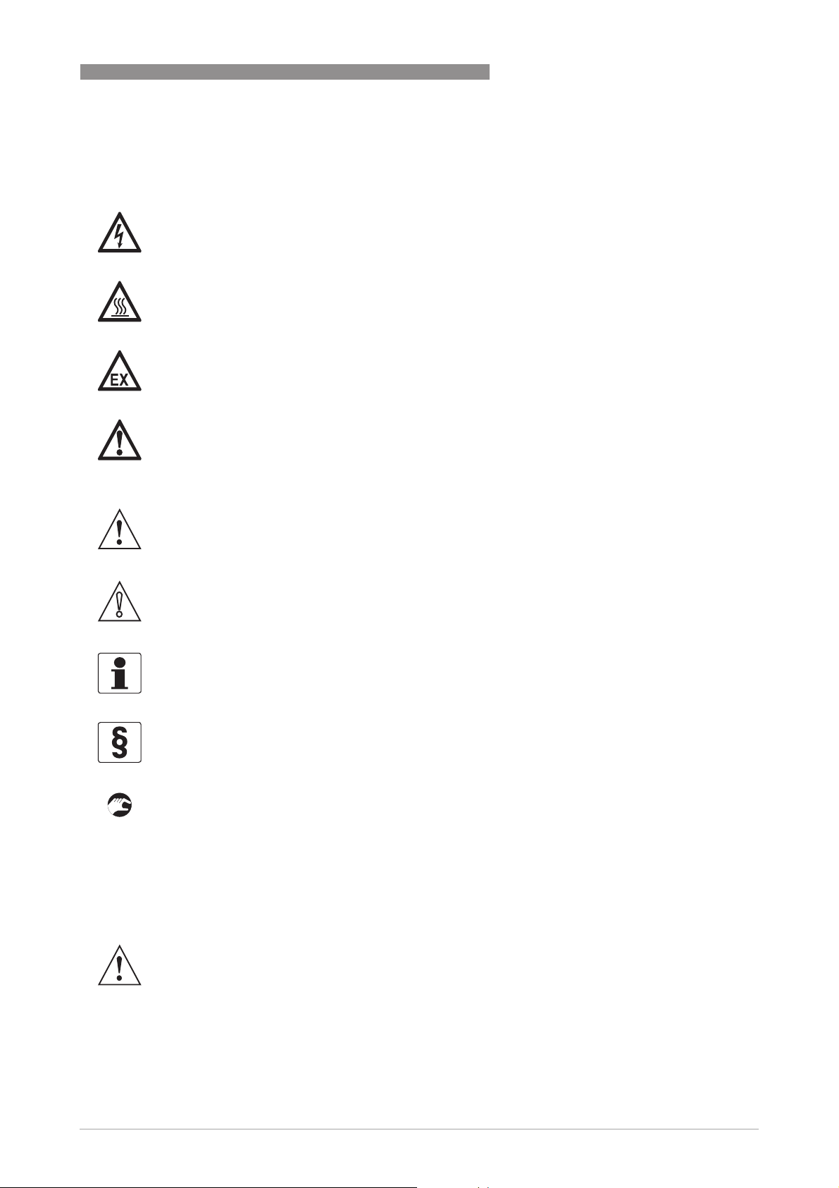
Safety warnings are indicated by the following symbols.
DANGER!
This warning refers to the immediate danger when working with electricity.
DANGER!
This warning refers to the immediate danger of burns caused by heat or hot surfaces.
DANGER!
This warning refers to the immediate danger when using this device in a hazardous atmosphere.
DANGER!
These warnings must be observed without fail. Even partial disregard of this warning can lead to
serious health problems and even death. There is also the risk of seriously damaging the device
or parts of the operator's plant.
SAFETY INSTRUCTIONS
1
WARNING!
Disregarding this safety warning, even if only in part, poses the risk of serious health problems.
There is also the risk of damaging the device or parts of the operator's plant.
CAUTION!
Disregarding these instructions can result in damage to the device or to parts of the operator's
plant.
INFORMATION!
These instructions contain important information for the handling of the device.
LEGAL NOTICE!
This note contains information on statutory directives and standards.
• HANDLING
HANDLING
HANDLINGHANDLING
This symbol designates all instructions for actions to be carried out by the operator in the
specified sequence.
i RESULT
RESULT
RESULTRESULT
This symbol refers to all important consequences of the previous actions.
1.7 Safety instructions for the operator
WARNING!
In general, devices from the manufacturer may only be installed, commissioned, operated and
maintained by properly trained and authorized personnel.
This document is provided to help you establish operating conditions, which will permit safe and
efficient use of this device.
www.krohne.com10/2016 - 4004375401 - MA OPTIWAVE 7500 R01 en
17
Page 18
2
DEVICE DESCRIPTION
2.1 Scope of delivery
INFORMATION!
Do a check of the packing list to make sure that you have all the elements given in the order.
Scope of delivery
OPTIWAVE 7500 C
Figure 2-1: Scope of delivery
1 Signal converter and antenna in the ordered version
2 Antenna extensions (option)
3 Quick start
4 Certificates and calibration report (if the device has the appropriate options)
5 DVD-ROM (including handbook, quick start, technical data sheet and related software)
6 Bar magnet
7 Handle (for removal of the optional display module)
8 Wrench (for removal of the device covers)
18
www.krohne.com 10/2016 - 4004375401 - MA OPTIWAVE 7500 R01 en
Page 19
OPTIWAVE 7500 C
2.2 Device description
This device is a 80 GHz FMCW-radar level transmitter. It is a non-contact technology and is 2wire loop-powered. It is designed to measure the distance, level, mass, volume and reflectivity of
liquids, pastes and slurries. For more data about the measuring principle,.
Radar level transmitters use an antenna to emit a signal to the surface of the measured product.
The device has many antennas available. Thus, it can measure most products even in difficult
conditions. Also refer to
If the device is ordered with the applicable options, it can be certified for use in hazardous areas.
The signal converter is attached directly to the process connection and the antenna. The
illustration that follows shows the types of antenna.
Technical data
on page 98.
DEVICE DESCRIPTION
2
Figure 2-2: Types of antenna
1 Lens antennas (available antenna sizes: Ø20 mm (0.75¨), Ø25 mm (1¨), Ø40 mm (1.5¨) and Ø70 mm (2.75¨) made of
PEEK)
These accessories are available:
• Stainless steel weather protection.
• RS232 / HART® converter (VIATOR).
• USB / HART® converter.
INFORMATION!
For more data on accessories.
www.krohne.com10/2016 - 4004375401 - MA OPTIWAVE 7500 R01 en
19
Page 20

2
DEVICE DESCRIPTION
2.3 Visual Check
WARNING!
If the display screen glass is broken, do not touch.
INFORMATION!
Inspect the packaging carefully for damages or signs of rough handling. Report damage to the
carrier and to the local office of the manufacturer.
OPTIWAVE 7500 C
Figure 2-3: Visual check
1 Device nameplate (for more data refer to
2 Process connection data (size and pressure rating, material reference and heat number)
3 Gasket material data – refer to the illustration that follows
Figure 2-4: Symbols for the supplied gasket material (on the side of the process connection)
1 EPDM
2 Kalrez® 6375
Nameplate (examples)
on page 21)
If the device is supplied with an FKM/FPM gasket, there is no symbol on the side of the process
connection.
INFORMATION!
Look at the device nameplate to ensure that the device is delivered according to your order.
Check for the correct supply voltage printed on the nameplate.
INFORMATION!
Compare the material references on the side of the process connection with the order.
20
www.krohne.com 10/2016 - 4004375401 - MA OPTIWAVE 7500 R01 en
Page 21
OPTIWAVE 7500 C
2.4 Nameplates
INFORMATION!
Look at the device nameplate to ensure that the device is delivered according to your order.
Check for the correct supply voltage printed on the nameplate.
2.4.1 Nameplate (examples)
DEVICE DESCRIPTION
2
Figure 2-5: Non-Ex nameplate attached to the housing
1 Cable entry size
2 Hardware revision / Software revision (according to NAMUR NE 53)
3 Signal output (analog, HART®, fieldbus, etc.), input voltage and maximum current (fieldbus options: basic current)
4 Degree of ingress protection (according to EN 60529 / IEC 60529)
5 Customer tag number
6 Date of manufacture
7 Order number
8 Type code (defined in order)
9 Model name and number. C = compact version.
10 Company logo, name and postal address
Country of manufacture / Company web address
www.krohne.com10/2016 - 4004375401 - MA OPTIWAVE 7500 R01 en
21
Page 22
3
INSTALLATION
3.1 General notes on installation
INFORMATION!
Inspect the packaging carefully for damages or signs of rough handling. Report damage to the
carrier and to the local office of the manufacturer.
INFORMATION!
Do a check of the packing list to make sure that you have all the elements given in the order.
INFORMATION!
Look at the device nameplate to ensure that the device is delivered according to your order.
Check for the correct supply voltage printed on the nameplate.
3.2 Storage
WARNING!
Do not keep the device in a vertical position. This will damage the antenna and the device will not
measure correctly.
OPTIWAVE 7500 C
• Store the device in a dry and dust-free location.
• Store the device in its original packing.
3.3 Transport
Figure 3-1: How to lift the device
1 Remove the converter before you lift the device with a hoist.
WARNING!
Lift the device carefully to prevent damage to the antenna.
3.4 Pre-installation requirements
INFORMATION!
Obey the precautions that follow to make sure that the device is correctly installed.
• Make sure that there is sufficient space on all sides.
22
www.krohne.com 10/2016 - 4004375401 - MA OPTIWAVE 7500 R01 en
Page 23
OPTIWAVE 7500 C
• Protect the signal converter from direct sunlight. If necessary, install the weather protection
accessory.
• Do not subject the signal converter to heavy vibrations. The devices are tested for vibration
and agree with EN 50178 and IEC 60068-2-6.
3.5 Pressure and temperature ranges
INSTALLATION
3
Figure 3-2: Pressure and temperature ranges
1 Temperature at the process connection
Non-Ex devices: The temperature range depends on the type of antenna, process connection and the seal material.
Refer to the table that follows.
Devices with Hazardous Location approvals: see supplementary instructions
2 Ambient temperature for operation of the display
-20...+70°C / -4...+158°F
If the ambient temperature is not between these limits, then this condition can stop the display. The device continues
to operate.
3 Ambient temperature
Non-Ex devices: -40...+80°C / -40...+185°F
Devices with Hazardous Location approvals: see supplementary instructions
WARNING!
The process connection temperature range must agree with the temperature limits of the
gasket material. The operating pressure range is subject to the process connection used and the
flange temperature.
For more data on pressure ratings,.
Figure 3-3: Ambient temperature / flange temperature, flange and threaded connection, in °C
www.krohne.com10/2016 - 4004375401 - MA OPTIWAVE 7500 R01 en
23
Page 24
3
INSTALLATION
3.6 Recommended mounting position
CAUTION!
Follow these recommendations to make sure that the device measures correctly. They have an
effect on the performance of the device.
We recommend that you prepare the installation when the tank is empty.
3.6.1 General notes
CAUTION!
Follow these recommendations to make sure that the device measures correctly.
Point the cable entries on the housing in the direction of the nearest tank wall.
OPTIWAVE 7500 C
3.6.2 Tanks with conical bottoms
Figure 3-4: Tanks with dish-shaped or conical bottoms
Dish-shaped or conical bottoms have an effect on the measuring range. The device cannot measure to the bottom of the
tank.
1 Axis of radar beam
2 Minimum level reading
3.7 Mounting restrictions
CAUTION!
Follow these recommendations to make sure that the device measures correctly. They have an
effect on the performance of the device.
We recommend that you prepare the installation when the tank is empty.
24
www.krohne.com 10/2016 - 4004375401 - MA OPTIWAVE 7500 R01 en
Page 25

OPTIWAVE 7500 C
3.7.1 General data for TLPR devices
CAUTION!
Do not install the device above objects in the tank (ladder, supports etc). Objects in the tank can
cause parasitic signals. If there are parasitic signals, the device will not measure correctly.
If it is not possible to install the device on another part of the tank, do an empty spectrum scan.
INFORMATION!
If possible, do not install a nozzle on the tank centerline.
3.7.2 Obstacles in the tank
Obstacles in the tank can cause parasitic signals. They have an effect on the performance of the
device.
CAUTION!
If there are parasitic signals, the device will not measure correctly. Parasitic signals are caused
by:
•
Objects in the tank.
•
Sharp corners that are perpendicular to the path of the radar beam.
INSTALLATION
3
Do an Empty Spectrum recording (refer to Operation
Operation) to remove parasitic signals with a filter.
OperationOperation
CAUTION!
Do not put the device near to the product inlet. If the product that enters the tank touches the
antenna, the device will measure incorrectly. If the product fills the tank directly below the
antenna, the device will also measure incorrectly.
Figure 3-5: Product inlets
1 The device is in the correct position.
2 The device is too near to the product inlet.
CAUTION!
Do not put the device near to the product inlet. If the product that enters the tank touches the
antenna, the device will measure incorrectly. If the product fills the tank directly below the
antenna, the device will also measure incorrectly.
www.krohne.com10/2016 - 4004375401 - MA OPTIWAVE 7500 R01 en
25
Page 26
3
INSTALLATION
3.7.3 Process connections
Requirements for flange connections
Figure 3-6: Flange connection
Equipment needed:
• Device
• Flange gasket (not supplied)
• Wrench (not supplied)
OPTIWAVE 7500 C
• Make sure the flange on the nozzle is level.
• Make sure that you use the applicable gasket for the flange dimensions and the process.
• Align the gasket correctly on the flange facing of the nozzle.
• Lower the antenna carefully into the tank.
• Make sure that you point the device in the correct direction. Refer to "Point the device in the
correct direction" in this section.
• Tighten the flange bolts.
i Refer to local rules and regulations for the correct torque to apply to the bolts.
Equipment needed:
• Device
• Gasket for G 1½ connection (not supplied)
• Thread seal tape (PTFE) for 1½ NPT connection (not supplied)
• 50 mm / 2¨ wrench (not supplied)
WARNING!
Do not tighten the connection to a torque more than 40 N
·
m / 29.5 lb·ft. If the connection is too
tight, this will damage the thread.
To prevent damage to the antenna, make sure that the minimum diameter of the hole for a
1
½
NPT or 2 NPT thread connection is not less than 43.4 mm / 1.71¨.
26
• Make sure the tank connection is level.
• ISO 228-1 (G) connection:
ISO 228-1 (G) connection: Make sure that you use the applicable gasket for the connection
ISO 228-1 (G) connection:ISO 228-1 (G) connection:
dimensions and the process.
• ISO 228-1 (G) connection:
ISO 228-1 (G) connection: Align the gasket correctly.
ISO 228-1 (G) connection:ISO 228-1 (G) connection:
• NPT connection:
NPT connection: Wind the thread seal tape around the process connection in agreement with
NPT connection:NPT connection:
good engineering practice.
• Lower the antenna carefully into the tank.
www.krohne.com 10/2016 - 4004375401 - MA OPTIWAVE 7500 R01 en
Page 27
OPTIWAVE 7500 C
• Turn the threaded connection on the antenna to attach the device to the process connection.
• Make sure that you point the device in the correct direction. Refer to "Point the device in the
correct direction" in this section.
• Tighten the connection to the correct torque (not more than 40 N·m/ 29.5lb·ft).
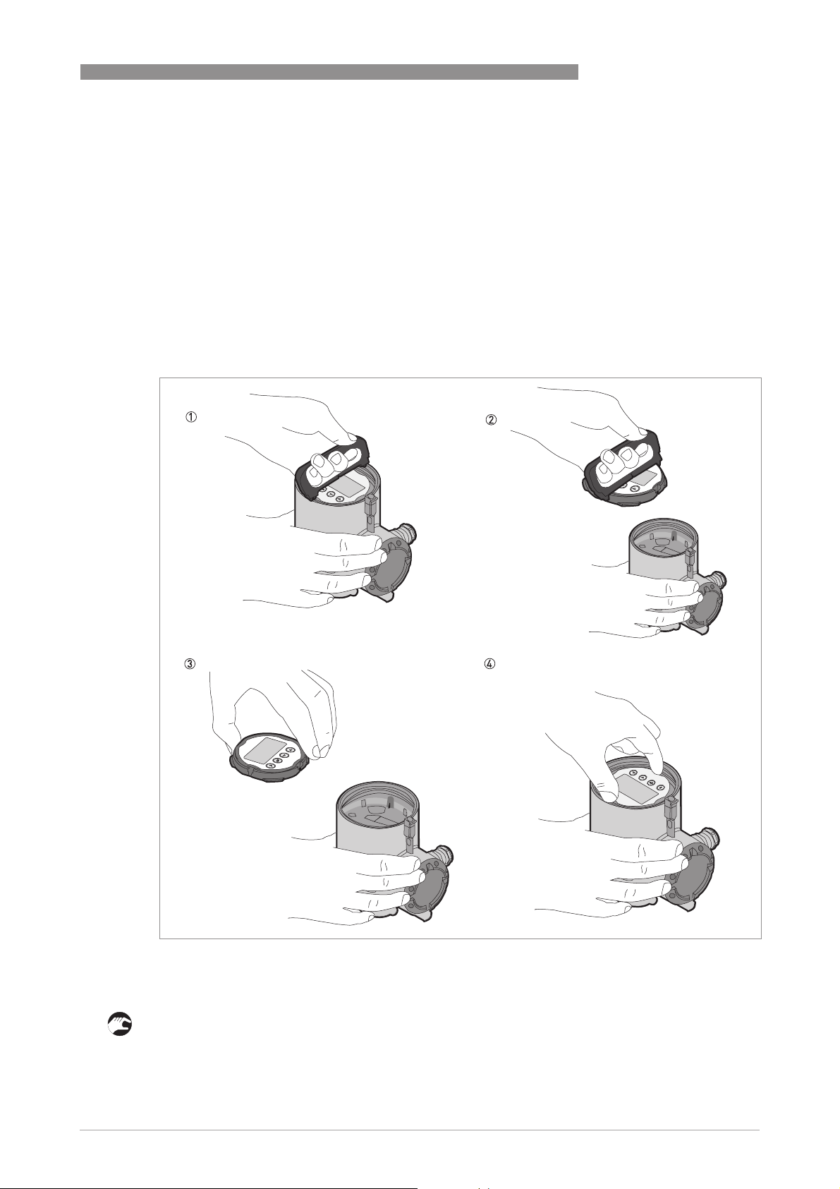
3.8 How to turn or remove the display module (option)
If there is an object adjacent to the device that makes it difficult to read the display, you can
rotate the display in increments of 90°.
INSTALLATION
3
Figure 3-7: How to turn or remove the display module (option)
1 Tool: Wrench (for removal of the device covers)
2 Tool: Handle (for removal of the display module)
Follow this procedure:
• Disconnect the power supply from the device.
• Remove the housing cover with the wrench 1.
www.krohne.com10/2016 - 4004375401 - MA OPTIWAVE 7500 R01 en
27
Page 28

3
INSTALLATION
• Use the handle to remove the display module.
• First put the handle on side "a" and then on side "b" of the display, and then carefully remove
the display 2 from housing. Remove the handle from the display module first on side "a" and
then on side "b".Turn it into the favoured position 3.
• Turn the display module until it points to the user.
• Push the display onto the clips in the housing 4, until they make a click.
• Make sure that the housing cover has a gasket. Attach the cover on the housing and tighten it
by hand.
INFORMATION!
Before you close the housing cover, refer to How to turn or remove the display module (option)
on page 27
.
3.9 How to turn or remove the signal converter
INFORMATION!
The converter turns 360
under process conditions.
°
. The converter can be removed from the process connection assembly
OPTIWAVE 7500 C
28
Figure 3-8: How to turn or remove the signal converter
1 Tool: 5 mm Allen wrench (not supplied)
2 Cover for the wave guide hole on top of the process connection assembly (not supplied)
CAUTION!
If you remove the converter, put a cover on the wave guide hole on top of the process connection
assembly.
When the converter is attached to the process connection assembly, tighten the lock screw.
www.krohne.com 10/2016 - 4004375401 - MA OPTIWAVE 7500 R01 en
Page 29
OPTIWAVE 7500 C
3.10 Weather protection
3.10.1 How to attach the weather protection to the device
Figure 3-9: Equipment needed to assemble the weather protection
1 Weather protection cover (with a split pin to hold the cover on the clamp)
2 Device
3 Weather protection clamp (2 parts)
4 2 locking nuts
5 10 mm socket wrench (not supplied).
INSTALLATION
3
The overall dimensions of the weather protection are on page 105.
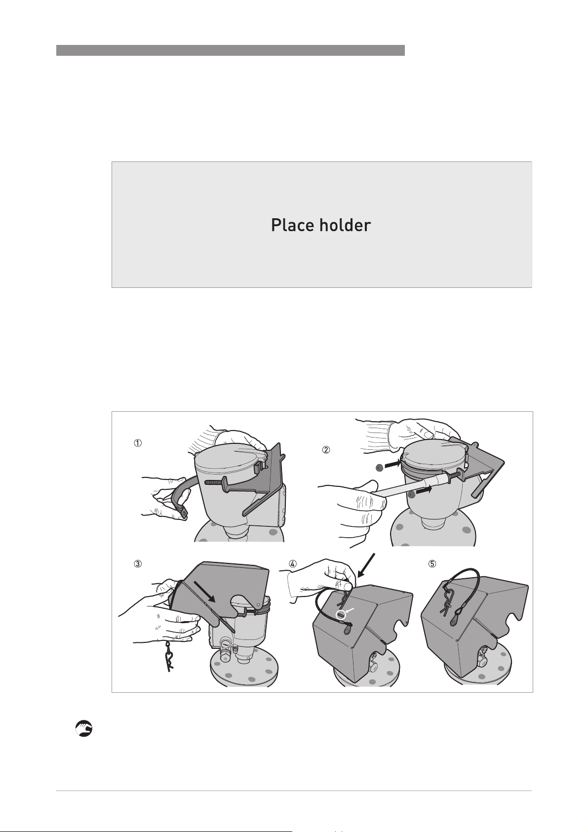
Figure 3-10: Installation of the weather protection
• Put the weather protection clamp around the top of the device.
• Attach the two locking nuts to the threads on the weather protection clamp. Tighten the
locking nuts with a 10 mm socket wrench.
www.krohne.com10/2016 - 4004375401 - MA OPTIWAVE 7500 R01 en
29
Page 30

3
INSTALLATION
• Lower the weather protection cover onto weather protection clamp until the hole for the lock
is in the slot at the front of the cover.
• Put the R-clip into the hole at the front of the weather protection cover.
• End of the procedure.
OPTIWAVE 7500 C
30
www.krohne.com 10/2016 - 4004375401 - MA OPTIWAVE 7500 R01 en
Page 31
OPTIWAVE 7500 C
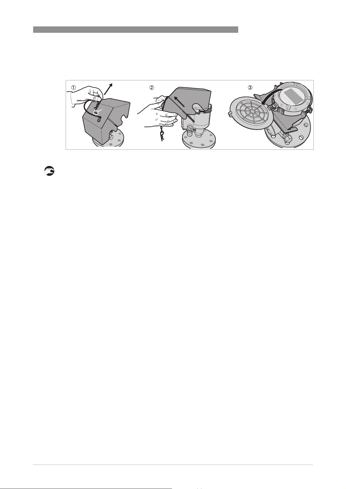
3.10.2 How to open the weather protection
Figure 3-11: How to open the weather protection
1 Remove the R-clip from the hole at the front of the weather protection cover.
2 Remove the weather protection cover.
i Lift the display screen cover.
INSTALLATION
3
www.krohne.com10/2016 - 4004375401 - MA OPTIWAVE 7500 R01 en
31
Page 32
4
ELECTRICAL CONNECTIONS
4.1 Safety instructions
DANGER!
All work on the electrical connections may only be carried out with the power disconnected. Take
note of the voltage data on the nameplate!
DANGER!
Observe the national regulations for electrical installations!
DANGER!
For devices used in hazardous areas, additional safety notes apply; please refer to the Ex
documentation.
WARNING!
Observe without fail the local occupational health and safety regulations. Any work done on the
electrical components of the measuring device may only be carried out by properly trained
specialists.
OPTIWAVE 7500 C
INFORMATION!
Look at the device nameplate to ensure that the device is delivered according to your order.
Check for the correct supply voltage printed on the nameplate.
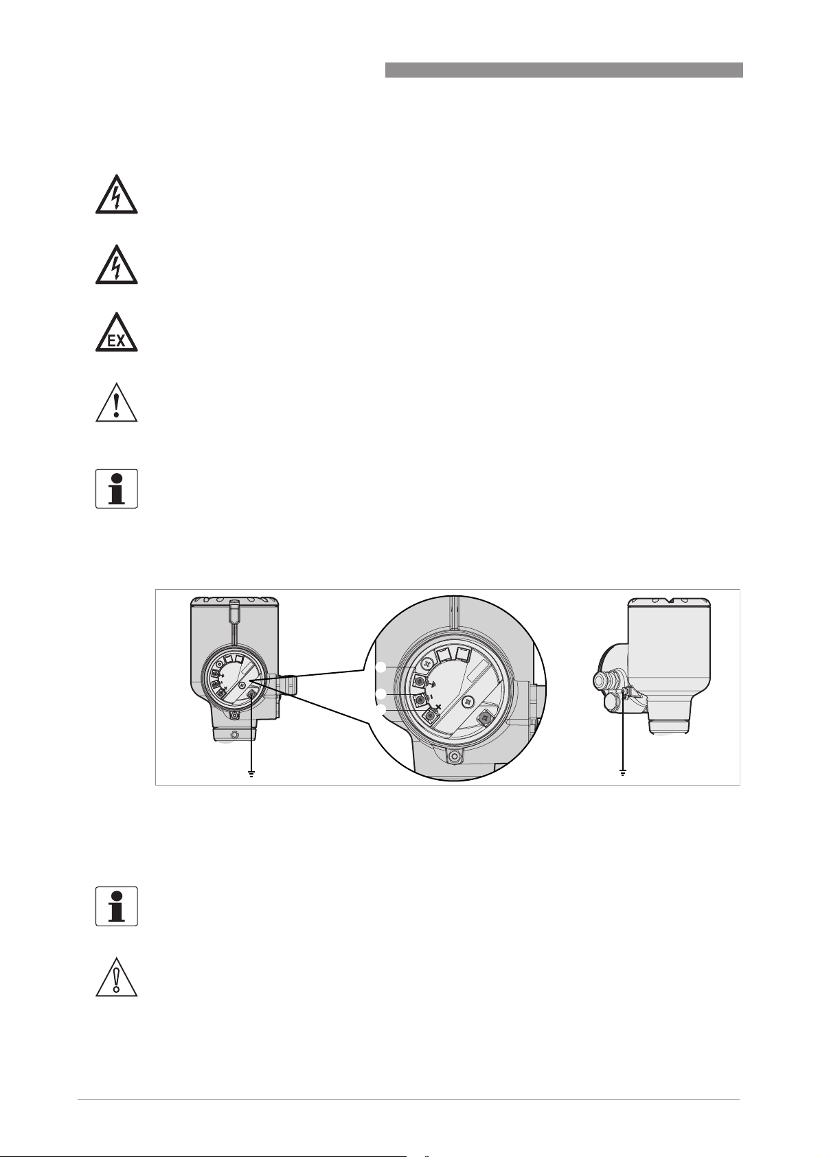
4.2 Electrical installation: 2-wire, loop-powered
Terminals for electrical installation
1
2
3
4
Figure 4-1: Terminals for electrical installation
1 Grounding terminal in the housing (if the electrical cable is shielded)
2 Current output -
3 Current output +
4 Location of the external grounding terminal (at the bottom of the converter)
4
32
INFORMATION!
Electrical power to the output terminal energizes the device. The output terminal is also used for
HART
®
communication.
CAUTION!
•
Use the applicable electrical cables with the cable glands.
•
Make sure that the current is not more than 5 A or that there is 5 A-rated fuse in the
electrical circuit that energizes the device.
www.krohne.com 10/2016 - 4004375401 - MA OPTIWAVE 7500 R01 en
Page 33
OPTIWAVE 7500 C
ELECTRICAL CONNECTIONS
4
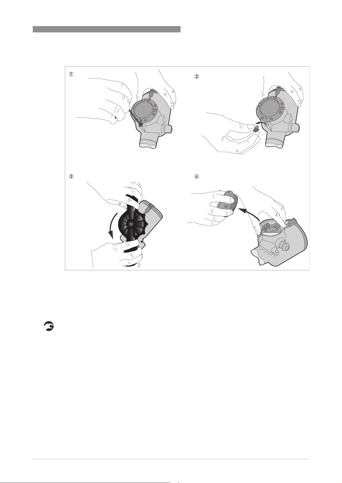
Figure 4-2: How to open the terminal compartment cover
Equipment needed:
• 3 mm Allen wrench (not supplied)
• Cover wrench (supplied).
Procedure
1 Loosen the lock screw with a 3 mm Allen wrench (not supplied).
2 Remove the cover stop.
3 Turn the cover counterclockwise with the cover wrench (supplied).
4 Remove the cover.
www.krohne.com10/2016 - 4004375401 - MA OPTIWAVE 7500 R01 en
33
Page 34
4
ELECTRICAL CONNECTIONS
OPTIWAVE 7500 C
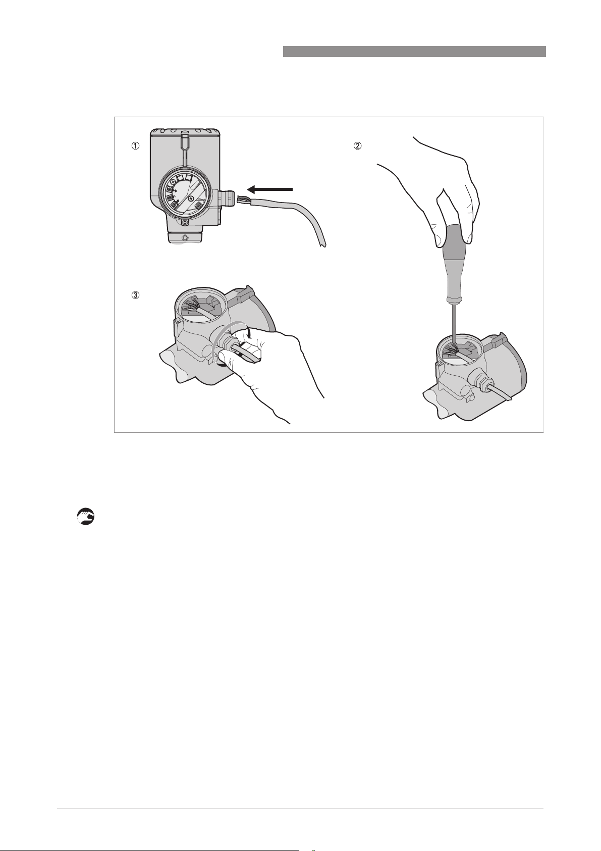
Figure 4-3: Procedure for electrical installation
Equipment needed:
• Small Phillips screwdriver (not supplied)
Procedure
1 Connect the electrical wires to the connector.
34
www.krohne.com 10/2016 - 4004375401 - MA OPTIWAVE 7500 R01 en
Page 35
OPTIWAVE 7500 C
ELECTRICAL CONNECTIONS
4
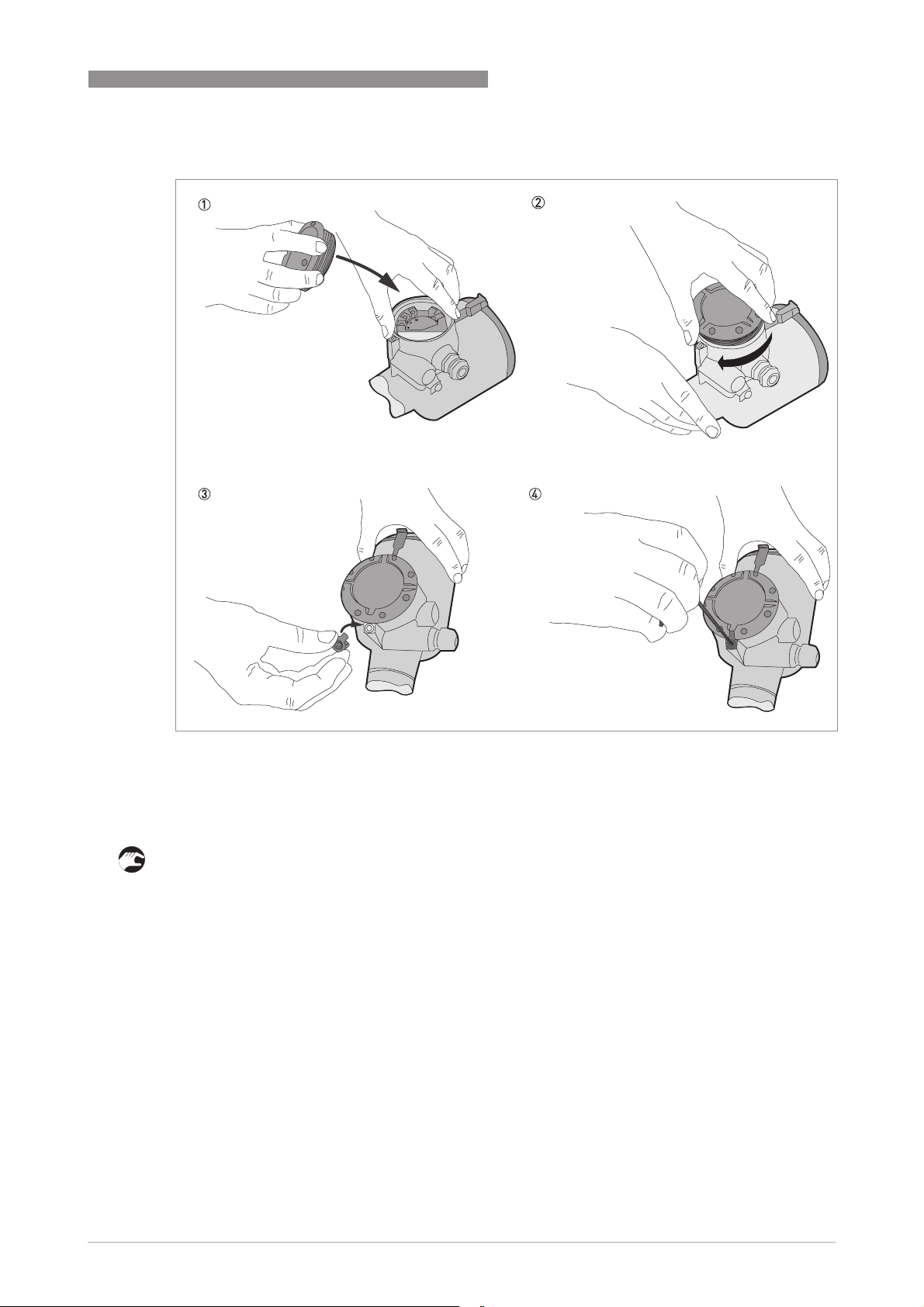
Figure 4-4: How to close the terminal compartment cover
Equipment needed:
• 3 mm Allen wrench (not supplied)
1 Put the cover on the housing and turn the cover clockwise until it is fully engaged.
2 Tighten the lock screw with a 3 mm Allen wrench (not supplied).
www.krohne.com10/2016 - 4004375401 - MA OPTIWAVE 7500 R01 en
35
Page 36

4
ELECTRICAL CONNECTIONS
4.3 Electrical connection for current output
4.3.1 Non-Ex devices
Figure 4-5: Electrical connections for non-Ex devices
1 Power supply
2 Resistor for HART® communication
3 Optional connection to the grounding terminal
4 Output: 12...30 VDC for an output of 22 mA at the terminal
5 Device
OPTIWAVE 7500 C
4.3.2 Devices for hazardous locations
DANGER!
For electrical data for device operation in hazardous locations, refer to the related certificates of
compliance and supplementary instructions (ATEX, IECEx, etc.). You can find this documentation
on the DVD-ROM delivered with the device or it can be downloaded free of charge from the
website (Download Center).
4.4 Protection category
INFORMATION!
The device fulfils all requirements per protection category IP66 / IP67.
DANGER!
Make sure that the cable gland is watertight.
36
Figure 4-6: How to make the installation agree with protection category IP67
• Make sure that the gaskets are not damaged.
• Make sure that the electrical cables are not damaged.
www.krohne.com 10/2016 - 4004375401 - MA OPTIWAVE 7500 R01 en
Page 37
OPTIWAVE 7500 C
• Make sure that the electrical cables agree with the national electrical code.
• The cables are in a loop in front of the device 1 so water does not go into the housing.
• Tighten the cable feedthroughs 2.
• Close unused cable feedthroughs with dummy plugs 3.
The diameter of the outer sheath of the electrical cable (for the power supply and current output)
must be 6…10 mm or 0.24…0.39¨.
4.5 Networks
4.5.1 General information
The device uses the HART® communication protocol. This protocol agrees with the HART®
Communication Foundation standard. The device can be connected point-to-point. It can also
have a polling address of 1 to 63 in a multi-drop network.
The device output is factory-set to communicate point-to-point. To change the communication
mode from point-to-point
4.5.2 Point-to-point connection
point-to-point to multi-drop
point-to-pointpoint-to-point
multi-drop,.
multi-dropmulti-drop
ELECTRICAL CONNECTIONS
4
Figure 4-7: Point-to-point connection (non-Ex)
1 Address of the device (0 for point-to-point connection)
2 4...20 mA + HART®
3 Resistor for HART® communication
4 Power supply
5 HART® converter
6 HART® communication software
www.krohne.com10/2016 - 4004375401 - MA OPTIWAVE 7500 R01 en
37
Page 38
4
ELECTRICAL CONNECTIONS
4.5.3 Multi-drop networks
Figure 4-8: Multi-drop network (non-Ex)
1 Address of the device (each device must have a different address in multidrop networks)
2 4mA + HART®
3 Resistor for HART® communication
4 Power supply
5 HART® converter
6 HART® communication software
OPTIWAVE 7500 C
38
www.krohne.com 10/2016 - 4004375401 - MA OPTIWAVE 7500 R01 en
Page 39
OPTIWAVE 7500 C
5.1 Start-up checklist
Check these points before you energize the device:
• Are all the wetted components (antenna, flange and gaskets) chemically resistant to the
product in the tank?
• Does the information on the signal converter nameplate agree with the operating data?
• Did you correctly install the device on the tank?
• Do the electrical connections agree with the national electrical codes? Use the applicable
electrical cables with the cable glands.
DANGER!
Before you energize the device, make sure that the supply voltage and polarity are correct.
5.2 How to start the device
• Connect the converter to the power supply.
• Energize the converter.
i Devices with the LCD display option only:
Devices with the LCD display option only: After 10 seconds the screen will display "Optiwave
Devices with the LCD display option only:Devices with the LCD display option only:
7500" and the logo of the supplier. After 40 seconds the default screen will appear. The
device will show measurement data. Measurements agree with specifications given in the
customer order.
START-UP
5
INFORMATION!
This chapter and the start of the chapter that follows tell you what data is given on the device
display in display mode and how to change device settings in configuration mode. If you know
about how this device operates, you can ignore this data. Continue with the quick setup
procedures. For more data about these procedures,.
5.3 Operating concept
You can read measurements and configure the device with:
• A digital display screen (optional).
• A connection to a system or PC with PACTware™. You can download the Device Type
Manager (DTM) file from the website. It is also supplied on the DVD-ROM delivered with the
device.
• A connection to a system or PC with AMS™. You can download the Device Description (DD)
file from the website. It is also supplied on the DVD-ROM delivered with the device.
• A connection to a HART® Field Communicator. You can download the Device Description (DD)
file from the website. It is also supplied on the DVD-ROM delivered with the device.
www.krohne.com10/2016 - 4004375401 - MA OPTIWAVE 7500 R01 en
39
Page 40
5
START-UP
5.4 Digital display screen
5.4.1 Display screen layout
Display in normal mode
OPTIWAVE 7500 C
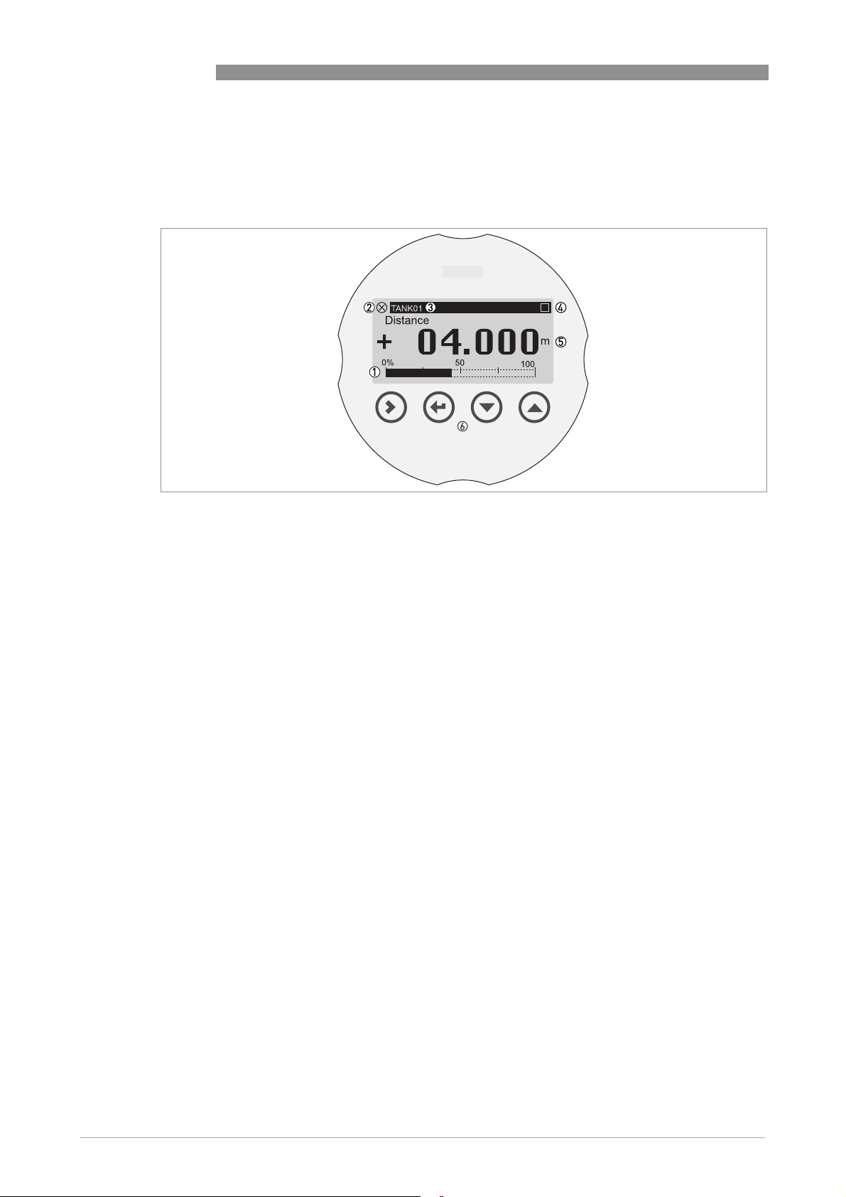
Figure 5-1: Display screen layout in normal mode (measurement data)
1 Current output percentage (bar graph)
2 Device status (NAMUR NE 107 symbols)
3 Device tag name
4 Keypad operation indicator (shown when you push a button or operate the keypad with a bar magnet)
5 Measurement value and units
6 Keypad buttons with Hall effect sensors (sensors sensitive to large changes in magnetic field strength)
If you remove the housing cover, you can push the buttons on the keypad. If you cannot remove
the housing cover, you can operate the keypad with a bar magnet.
The output percentage bar graph is only shown if you set "One Value and Bar" or "Two Values
and Bar" in menu items C6.4.1 Function
Function (1st Meas. page) or C6.5.1 Function
FunctionFunction
Function (2nd Meas. Page). If
FunctionFunction
menu item C6.4.2 1st Value Variable (1st Meas. page) is set to "Level", then the device shows
"Level" as the current output percentage in normal mode (refer to item 1 in the illustration).
40
www.krohne.com 10/2016 - 4004375401 - MA OPTIWAVE 7500 R01 en
Page 41
OPTIWAVE 7500 C
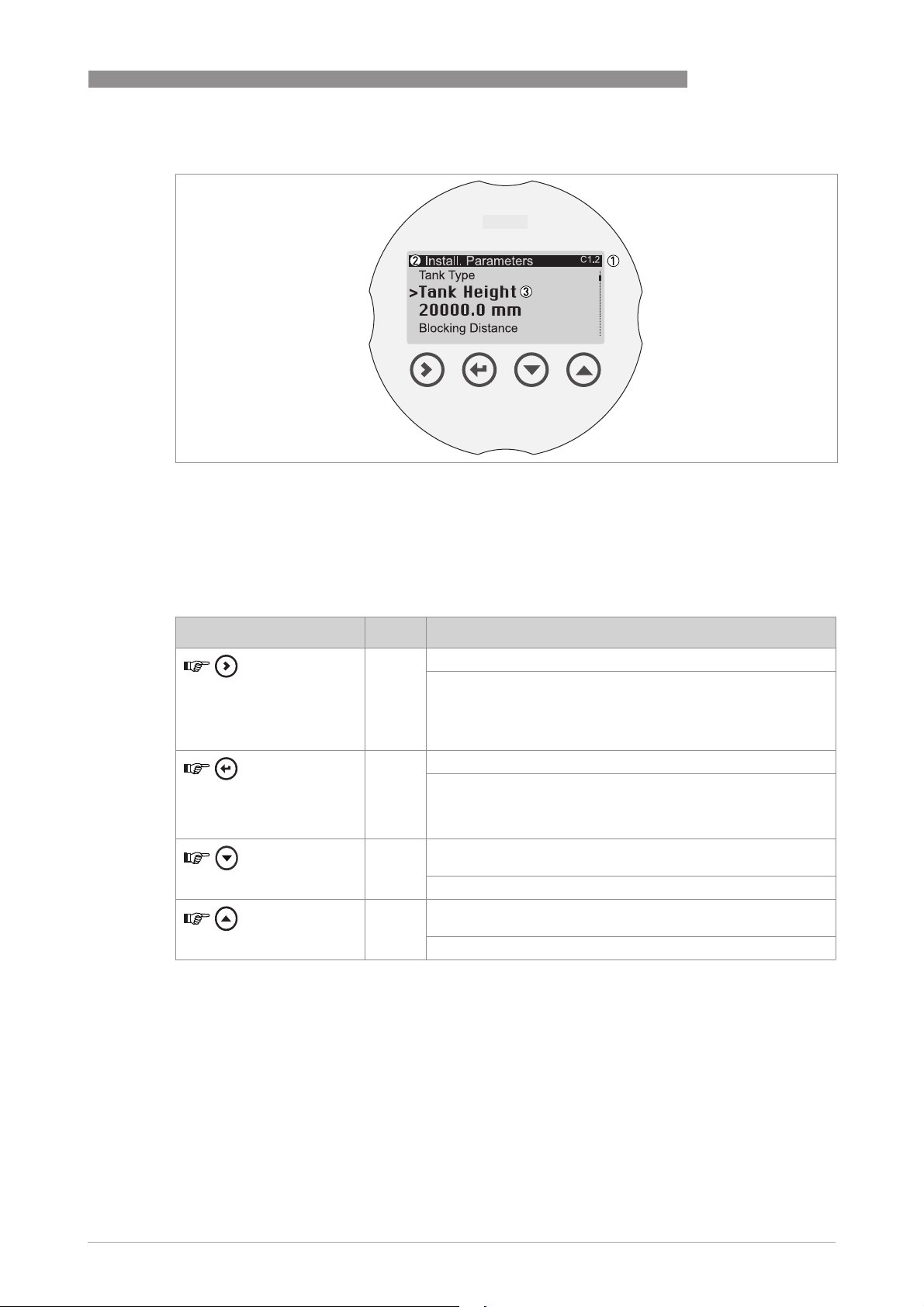
Display in program mode
Figure 5-2: Display screen layout in program mode
1 Menu number or menu item number
2 Location (menu) of sub-menu or menu item
3 Menu item name
START-UP
5
5.4.2 Keypad buttons
Functions of keypad buttons
Keypad button Symbol Function
[Right]
[Return / Escape]
[Down]
[Up]
For more data on keypad functions,.
[>>>>] Normal mode:
[^^^^] Normal mode:
[] Normal mode:
[] Normal mode:
Normal mode: Enter Program mode
Normal mode:Normal mode:
Configuration mode:
Configuration mode:
Configuration mode:Configuration mode:
Menu:
Menu: Enter the sub-menu or menu item
Menu:Menu:
Menu item:
Menu item: Move cursor one digit to the right (this includes the
Menu item:Menu item:
decimal point). If the cursor is on the last digit, a push of this
button will move the cursor to the first digit.
Normal mode: None
Normal mode:Normal mode:
Configuration mode:
Configuration mode:
Configuration mode:Configuration mode:
Menu:
Menu: Exit the menu. If you are in the top level menu (R), the
Menu:Menu:
device goes back to normal mode.
Menu item:
Menu item: Exit the menu item.
Menu item:Menu item:
Normal mode: Change screen (measurement pages 1 and 2 and
Normal mode:Normal mode:
the status message page)
Configuration mode:
Configuration mode: Decrease value or change parameter
Configuration mode:Configuration mode:
Normal mode: Change screen (measurement pages 1 and 2 and
Normal mode:Normal mode:
the status message page)
Configuration mode:
Configuration mode: Increase value or change parameter
Configuration mode:Configuration mode:
www.krohne.com10/2016 - 4004375401 - MA OPTIWAVE 7500 R01 en
41
Page 42
5
START-UP
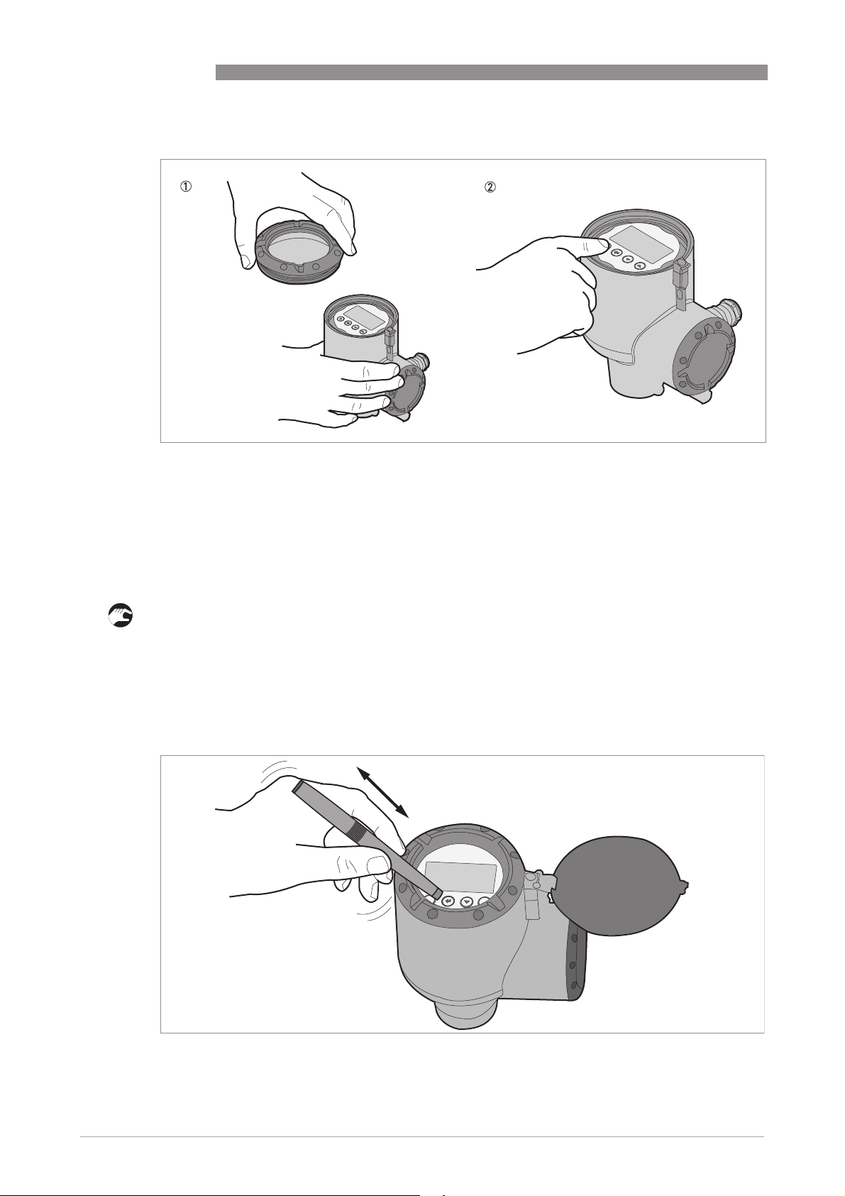
How to push the keypad buttons with your hand
Figure 5-3: How to push the keypad buttons with your hand
1 Display housing cover
2 Keypad
OPTIWAVE 7500 C
Equipment needed
• Wrench for the housing cover (supplied)
• 2.5 mm Allen wrench (not supplied)
• Undo the housing cover locking screw with a 2.5 mm Allen wrench.
• Remove the housing cover with the wrench supplied with the device.
• Push the buttons on the keypad.
i This will operate the device. Refer also to the table at the start of this section.
How to operate the keypad buttons with a bar magnet
42
www.krohne.com 10/2016 - 4004375401 - MA OPTIWAVE 7500 R01 en
Page 43

OPTIWAVE 7500 C
Figure 5-4: How to operate the keypad buttons with a bar magnet
1 Display housing cover
2 Keypad
3 Bar magnet
Equipment needed
• Bar magnet (supplied)
INFORMATION!
It is not necessary to remove the display housing cover to do this procedure.
• Hold the bar magnet near to a keypad button.
i The keypad button will operate. If you must operate the button more than one time, remove
the bar magnet and then hold it near to the button again.
5.5 Remote communication with PACTware™
START-UP
5
PACTware™ displays measurement information clearly and lets you configure the device from a
remote location. It is an Open Source, open configuration software for all field devices. It uses
Field Device Tool (FDT) technology. FDT is a communication standard for sending information
between the system and the field device. This standard agrees with IEC 62453. Field devices are
easily integrated. Installation is supported by a user-friendly Wizard.
Install these software programs and equipment:
• Microsoft® .NET Framework version 1.1 or later.
• PACTware.
• HART® converter (USB, RS232...).
• The Device Type Manager (DTM) for the device.
The software and installation instructions are given on the DVD-ROM supplied with the device.
You can also download the latest version of PACTware™ and the DTM from our website.
Refer also to the PACTware™ consortium site at http://www.pactware.com.
www.krohne.com10/2016 - 4004375401 - MA OPTIWAVE 7500 R01 en
43
Page 44
5
START-UP
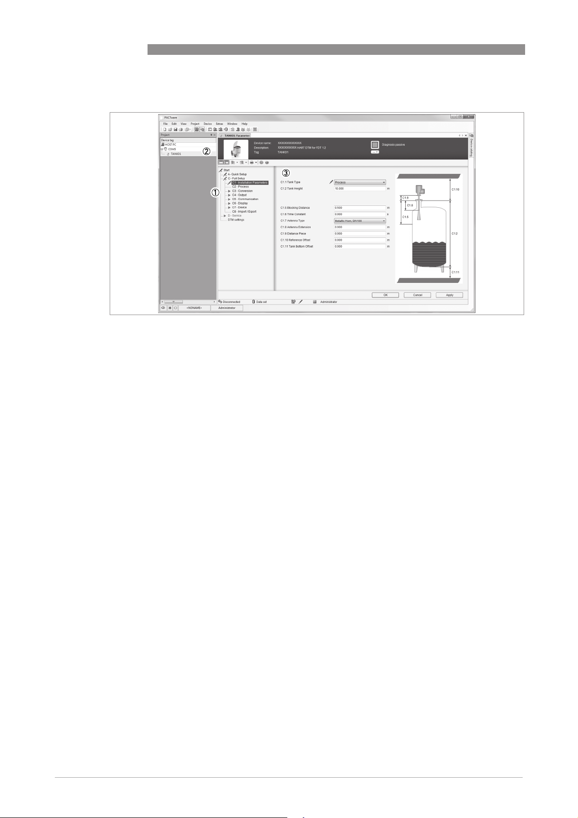
Figure 5-5: Screen from the PACTware™ user interface
1 DTM menu
2 Information for device identification
3 Installation parameters menu and menu items
OPTIWAVE 7500 C
5.6 Remote communication with the AMS™ Device Manager
The AMS™ Device Manager is an industrial Plant Asset Management (PAM) software tool. Its
role is to:
• Store configuration information for each device.
• Store and read process data.
• Store and read diagnostic status information.
• Help plan preventive maintenance to reduce a plant's downtime to a minimum.
The DD file is given on the DVD-ROM supplied with the device. You can also download it from our
website.
44
www.krohne.com 10/2016 - 4004375401 - MA OPTIWAVE 7500 R01 en
Page 45
OPTIWAVE 7500 C
6.1 User modes
Normal mode
Normal mode This mode shows measurement data and status messages. For more data,.
Normal modeNormal mode
Program mode
Program mode Use this mode to read and change parameters, commission the device,
Program modeProgram mode
6.2 Normal mode
This mode shows measurement data. Use the display keypad to change the type of
measurement data shown on the screen (on 2 "measurement data pages") and to read the
device status message page.
OPERATION
create tables for volume or mass measurement, and change critical values
to measure in difficult process conditions.To change settings in Program
mode, you must use the device with the correct security level (user,
operator or expert). For more data about menu items,.
All users can read the settings in Program mode, but only users with
"Operator" and "Expert" security levels can change settings. For more data
about security levels,.
6
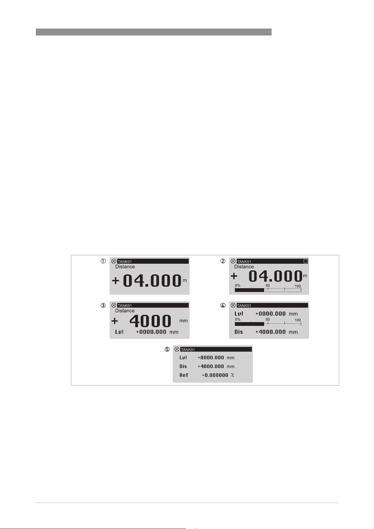
There are 5 options to show the measurement data on the display screen. Refer to the
illustration that follows:
Measurement data options
Figure 6-1: Measurement data options in normal mode
1 One value
2 One value and current output (%) bar
3 Two values
4 Two values and current output (%) bar
5 Three values
www.krohne.com10/2016 - 4004375401 - MA OPTIWAVE 7500 R01 en
45
Page 46
6
OPERATION
INFORMATION!
Go to C6.4.1 Function
Display > 2nd Measur. Page
Display > 2nd Measur. Page) in Program mode to change the layout of the display screen.
Display > 2nd Measur. PageDisplay > 2nd Measur. Page
Users of all security levels can change this setting.
Measurement data includes different measurement types (level, distance volume, ullage
volume, mass etc.). Some measurement tyypes will only be available if you entered the correct
parameters in Program mode.
Measurement data format errors
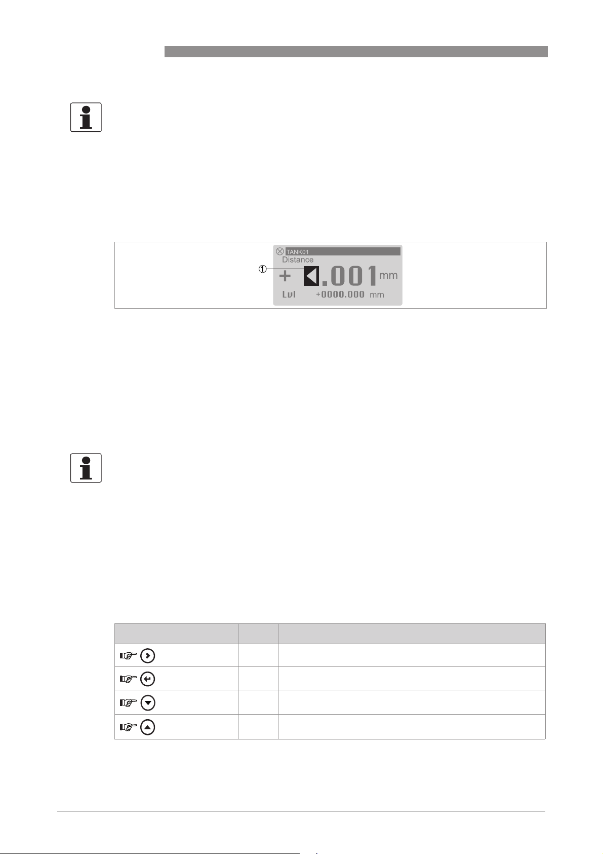
Figure 6-2: Error symbol: the number of digits and decimal places is not sufficient for the measurement data
1 Error symbol: the number of digits and decimal places is not sufficient for the measurement data. It is possible that
the length units must be changed from "mm" to "m".
Function or C6.5.1 Function
FunctionFunction
Function (Full Setup > Display > 1st Measur. Page
Function Function
OPTIWAVE 7500 C
Full Setup > Display > 1st Measur. Page or Full Setup >
Full Setup > Display > 1st Measur. PageFull Setup > Display > 1st Measur. Page
Full Setup >
Full Setup > Full Setup >
In this example, the device measures a distance of 10 m, but C7.5.1 Length Unit is set to mm and
menu C6.4.5 Format 1st Value is set to X.XXXX (five digits with four decimal places). This is not
sufficient to measure 10 m.
You can change the number of digits and decimal places in the measurement values shown in
normal mode.
INFORMATION!
Go to C6.4.5 Format 1st value
1st value
1st value, C6.5.7 Format 2nd value
1st value1st value
Page
Page or Full Setup > Display > 2nd Measur. Page
PagePage
Format 1st value, C6.4.7 Format 2nd value
Format 1st valueFormat 1st value
Format 2nd value or C6.5.9 Format 3rd value
Format 2nd valueFormat 2nd value
Full Setup > Display > 2nd Measur. Page) in Program mode to change the number of
Full Setup > Display > 2nd Measur. PageFull Setup > Display > 2nd Measur. Page
Format 2nd value, C6.4.9 Format 3rd value
Format 2nd valueFormat 2nd value
Format 3rd value (Full Setup > Display > 1st Measur.
Format 3rd valueFormat 3rd value
Format 3rd value, C6.5.5 Format
Format 3rd valueFormat 3rd value
Full Setup > Display > 1st Measur.
Full Setup > Display > 1st Measur. Full Setup > Display > 1st Measur.
Format
Format Format
digits and decimal places. If there is a large change in a measurement value, set the related
menu item to "Automatic".
Volume measurement
You must make a conversion table (strapping table) to show measurement data as a volume or a
mass. Go to C3.2 Input table (Full Setup > Conversion
data,.
Full Setup > Conversion) to make the strapping table. For more
Full Setup > ConversionFull Setup > Conversion
Functions of keypad buttons (normal mode)
Keypad button Symbol Function
[Right]
[Return / Escape]
[Down]
[Up]
[>>>>] Enter Program mode
[^^^^] —
[] Change screen (measurement pages 1 and 2, and the status
message page)
[] Change screen (measurement pages 1 and 2 and the status
message page)
46
www.krohne.com 10/2016 - 4004375401 - MA OPTIWAVE 7500 R01 en
Page 47
OPTIWAVE 7500 C
6.3 Program mode
6.3.1 General notes
OPERATION
6
Change the settings of your device in Program
• Use the A Quick Setup
change settings, do standard setup and empty recording procedures.
• Use the B Test
• Use the C Full Setup
or mass measurement, change current output values, use the device as a limit switch,
change HART® settings, change how the measurement data is shown in normal mode, read
device identification data, change critical parameters for difficult process conditions, change
the password, change measurement units or reset the device to factory default settings.
A Quick Setup menu to change the display language, change the tag name, log in to
A Quick SetupA Quick Setup
B Test menu to run diagnostic tests, read measurement and spectrum data.
B TestB Test
C Full Setup menu to change settings. You can set up a conversion table for volume
C Full SetupC Full Setup
Program mode. Data about the menus is given. You can:
ProgramProgram
CAUTION!
If you did not supply all installation data to the supplier before the delivery, the standard setup
procedure in the Quick Setup menu is mandatory.
INFORMATION!
It is not possible to enter the D Service
D Service menu. This menu is for factory calibration and approved
D ServiceD Service
personnel only.
6.3.2 Protection of the device settings (security levels)
The settings of this device have three levels of data protection: "User", "Operator" and "Expert".
"Expert" is the highest level of protection. It is necessary to enter a different password for
"Operator" and "Expert" security levels. There is no password for the "User" security level.
Security levels and applicable functions in program mode
Security level
Security level Default password
Security levelSecurity level
Expert 0058
Default password Applicable functions in program mode (overview)
Default passwordDefault password
Applicable functions in program mode (overview)
Applicable functions in program mode (overview)Applicable functions in program mode (overview)
•
Read: Measurement data and error messages available at
the "User" security level (normal mode and menu items B2
Actual Values and C7.3.1 Message View)
•
Change: All sub-menus in menus A Quick Setup, B Test and
C Full Setup
NOTE:
NOTE: You can change the password for the "Expert" security
NOTE:NOTE:
level in menu item C7.2.2 Change Password. Refer to the
INFORMATION! note that follows.
www.krohne.com10/2016 - 4004375401 - MA OPTIWAVE 7500 R01 en
47
Page 48
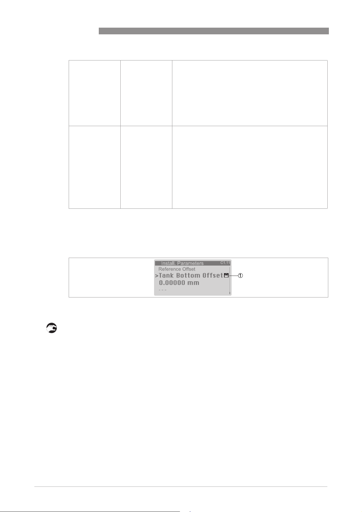
6
OPERATION
OPTIWAVE 7500 C
Operator 0009
User —
•
Read: Measurement data and error messages available at
the "User" security level (normal mode and menu items B2
Actual Values and C7.3.1 Message View)
•
Change: Binary Output (C4.3)
•
Change: All HART® settings (C5) – but not C5.1.1 Current
Loop Mode
NOTE:
NOTE: You can change the password for the "Operator"
NOTE:NOTE:
security level in menu item C7.2.2 Change Password. Refer to
the INFORMATION! note that follows.
•
Read: Measurement data and error messages (normal mode
and men items B2 Actual Values and C7.3.1 Message View)
•
Read: All settings in menus A Quick Setup, B Test and C Full
Setup
•
Change: All settings in menu C6 Display (language, backlight
on/off, screen contrast and measurement data display
options (normal mode, pages 1 and 2)) and C7.5 Units
(length, volume, mass and custom units)
•
Change: Security level. Go to menu item A3 Login or C7.2.1
Login to change from "User" to "Operator" or "Expert"
security levels
If your security level is too low, the display will show a "lock" symbol adjacent to menu items in
Program mode. If it is necessary to change this setting, go to menu item menu item A3 Login or
C7.2.1 Login and set the device to the correct security level.
Figure 6-3: Lock symbol
1 Lock symbol. If the display shows this symbol, you cannot change the setting.
How to change the password
• Push [>>>>] to enter Program Mode.
• Push 2 × [], [>>>>], 5 × [], [>>>>], [] and [>>>>] to go to the menu item C7.2.1 Login.
• Push [>>>>] to enter the menu item.
• Enter the password used at this time for a given security level ("Operator" or "Expert"). If it is
the default password, refer to the table at the start of this section.
• Push [^^^^] and [] to go to the menu item C7.2.2 Change Password.
• Push [>>>>] to enter the menu item.
• Enter the password used at this time for the security level set at the start of this procedure. If
it is the default password, refer to the table at the start of this section.
• Enter the new password.
i If you change the password for the "Operator" security level, then the first three digits must
be zero (000x). The last digit can be a number (1...9) or a letter (A...F). If you change the
password for the "Expert" security level, then the first two digits must be zero (00xx). The
last two digits can be a number (1...9) or a letter (A...F).
• Enter the new password again.
• Push 6 × [^^^^] to go back to normal mode.
48
www.krohne.com 10/2016 - 4004375401 - MA OPTIWAVE 7500 R01 en
Page 49
OPTIWAVE 7500 C
i End of the procedure.
INFORMATION!
Each security level has a four-digit hexadecimal password.
The first three digits of the password for the "Operator" security level must be zero (000x). The
last digit can be a number (1...9) or a letter (A...F).
The first two digits of the password for the "Expert" security level must be zero (00xx). The last
two digits can be a number (1...9) or a letter (A...F).
INFORMATION!
Make a note of the password and keep it in a safe place. If you lose the password, please speak
or write to your supplier.
INFORMATION!
If you de-energize and then energize the device, the security level will go back to "User".
OPERATION
6
6.3.3 How to get access to the Quick Setup menu
The Quick Setup menu contains the menu items that are necessary for most configurations of
the device. The menu items are divided into 2 groups: "Standard Setup" and "Empty Spectrum".
The "Standard Setup" group lets the user (with security level "expert") set the tank height, tank
type (process, storage etc.), output variable, output current range, 0% range, 100% range, error
function and error delay. "Empty Spectrum" is a procedure that finds interference signals in the
tank and uses a filter to remove them from the measurement data.
Do the steps that follow:
• Push [>>>>] to enter Program Mode.
• Push [>>>>], 2 × [] to go to the menu item A3 Login.
• Enter the password used at this time for the "Expert" security level. If it is the default
password, refer to
• Push [^^^^], [] and [>>>>] to go to the menu item A4.1 Standard Setup.
• Push [>>>>]. Do the basic configuration of the device in the "Standard Setup" menu. For more data
on the procedure, refer to
procedure to continue to the next step.
• Push [] and [>>>>] to go to the menu item A4.2.1 Record Spectrum.
• Push [>>>>] to start the empty spectrum recording procedure. For more data,. Push [^^^^] at the end
of each step of the procedure to continue to the next step.
CAUTION!
If you did not supply all installation data to the supplier before the delivery, the standard setup
procedure in the Quick Setup menu is mandatory.
Protection of the device settings (security levels)
Standard Setup
on page 79. Push [^^^^] at the end of each step of the
on page 47.
www.krohne.com10/2016 - 4004375401 - MA OPTIWAVE 7500 R01 en
49
Page 50
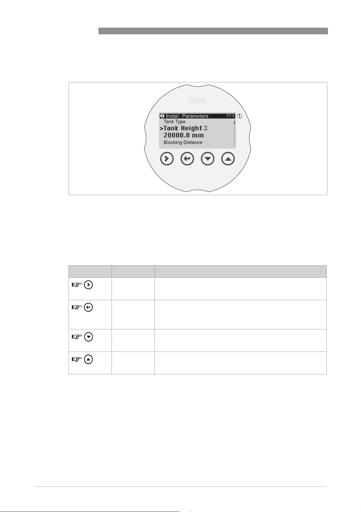
6
OPERATION
6.3.4 Keypad functions
Menu navigation
Figure 6-4: Menu navigation
1 Menu number or menu item number
2 Location (menu) of sub-menu or menu item
3 Menu item name
OPTIWAVE 7500 C
This is what you see when you are in Program mode. The functions of the buttons are given in the
table that follows:
Functions of buttons for menu navigation
Button Description Function
Right
Enter / Esc
(Escape)
Down
Up
•
Go down a menu level (for example, from menu C1 to sub-menu
C1.1).
•
Enter the menu item.
•
Go up a menu level (for example, from sub-menu C1.1 to menu C1).
•
Go to Normal mode. If you changed settings in Program mode, you
must save or cancel your new settings. For more data, refer to
to save settings changed in program mode
•
Scroll down the menu list (for example, from menu C1 to menu C2.
•
Scroll down the sub-menu list (for example, from sub-menu C2.1 to
sub-menu C2.2).
•
Scroll up the menu list (for example, from menu C2 to menu C1).
•
Scroll up the sub-menu list (for example, from sub-menu C2.2 to
sub-menu C2.1).
on page 53.
How
50
www.krohne.com 10/2016 - 4004375401 - MA OPTIWAVE 7500 R01 en
Page 51
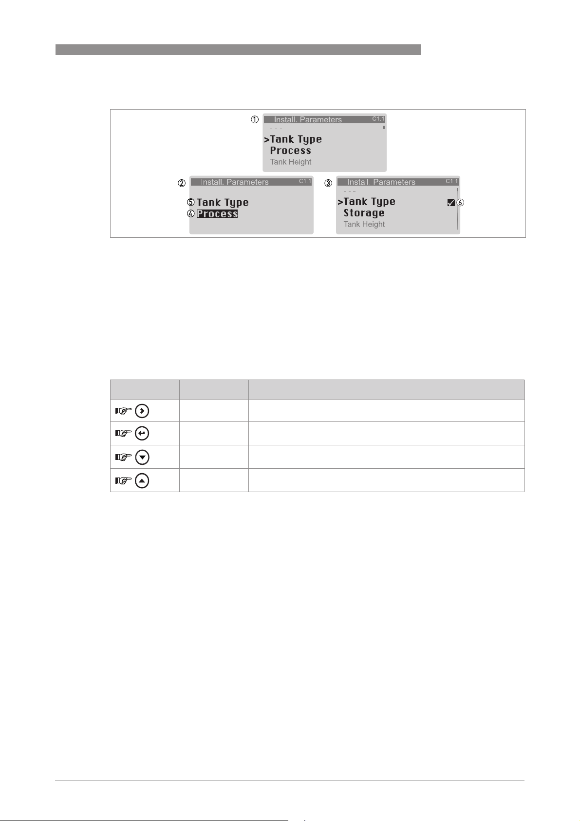
OPTIWAVE 7500 C
Lists of parameters in menu items
Figure 6-5: Lists of parameters in menu items
1 Menu item with parameter stored at this time (first screen). Push [>>>>] to enter the menu item.
2 Push [] or [] to change the parameter
3 Push [^^^^] to set the new parameter and go back to the menu level
4 Parameter
5 Menu item name
6 A "tick" symbol shows that there is a new setting (the new setting is not saved at this time)
This is what you see when you select a menu item that has a list of parameters. The functions of
the buttons are given in the table that follows:
OPERATION
6
Function of buttons in menu items that have a list of parameters
Button Description Function
Right —
Enter / Esc
(Escape)
Down Move down the list
Up Move up the list
Select the parameter and go back to the menu
www.krohne.com10/2016 - 4004375401 - MA OPTIWAVE 7500 R01 en
51
Page 52
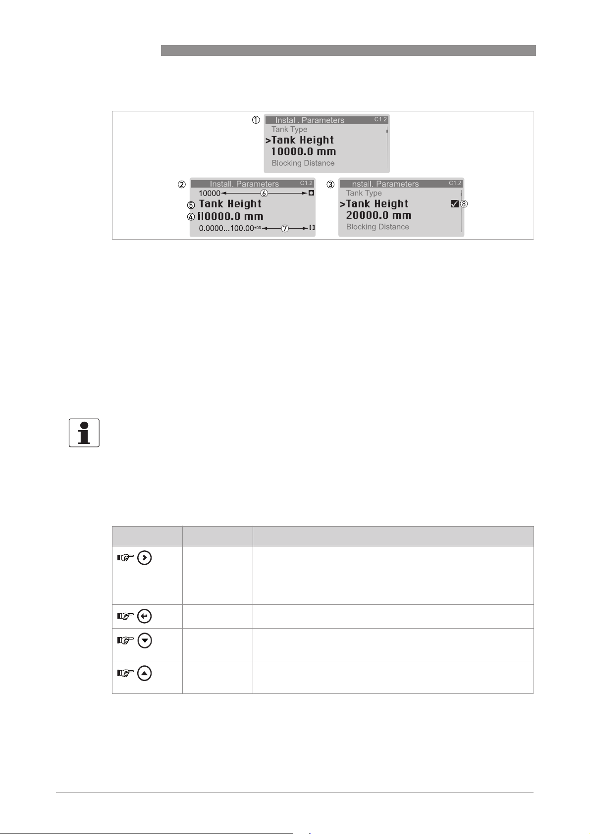
6
OPERATION
Values in menu items
Figure 6-6: Values in menu items
1 Menu item with values stored at this time (first screen). Push [>>>>] to enter the menu item. A cursor shows on the first
digit.
2 Push [>>>>] again and again to move the cursor. Push [] or [] to change the value of the digit. If the digit is part of a
number, then make a selection from 0...9. If the digit is part of a custom unit name, then refer to the tables at the end
of this section for a list of the available characters. If the cursor is on the decimal point, you can change the position
of the decimal point.
3 Push [^^^^] to set the new parameter and go back to the menu level
4 Make a selection: put the cursor on a digit or the decimal point.
5 Menu item name
6 The factory default value (left side) and factory default symbol (right side)
7 The minimun and maximum values (min./max.) for this menu item (left side) and min./max. symbol (right side)
8 A "tick" symbol shows that there is a new setting (the new setting is not saved at this time)
OPTIWAVE 7500 C
This is what you see when you select a menu item that has a value.
INFORMATION!
If menu items have values that you can change, very large and very small values can be written
as a value with an exponent (b
3
value is equal to 100 × 10
or 100000.
n
). For example, if the value shown on the display is 100.00
+03
, this
The functions of the buttons are given in the table that follows:
Function of buttons in menu items that have values
Button Description Function
Right
Enter / Esc
(Escape)
Down If the cursor is on a number, this button decreases the digit value. If
Up If the cursor is on a number, this button increases the digit value. If
•
Enter the menu item and see the value stored at this time.
•
Enter the menu item configuration level to change the value.
•
Move the cursor to the next digit on the right. If the cursor is on the
last digit, push [>>>>] again to go back to the first digit. You can also put
the cursor on the decimal point.
Accept the value and go back to the sub-menu.
the cursor is on the decimal point, this button moves the decimal
point to the left (this decreases the value by a factor of 10).
the cursor is on the decimal point, this button moves the decimal
point to the right (this increases the value by a factor of 10).
52
www.krohne.com 10/2016 - 4004375401 - MA OPTIWAVE 7500 R01 en
Page 53
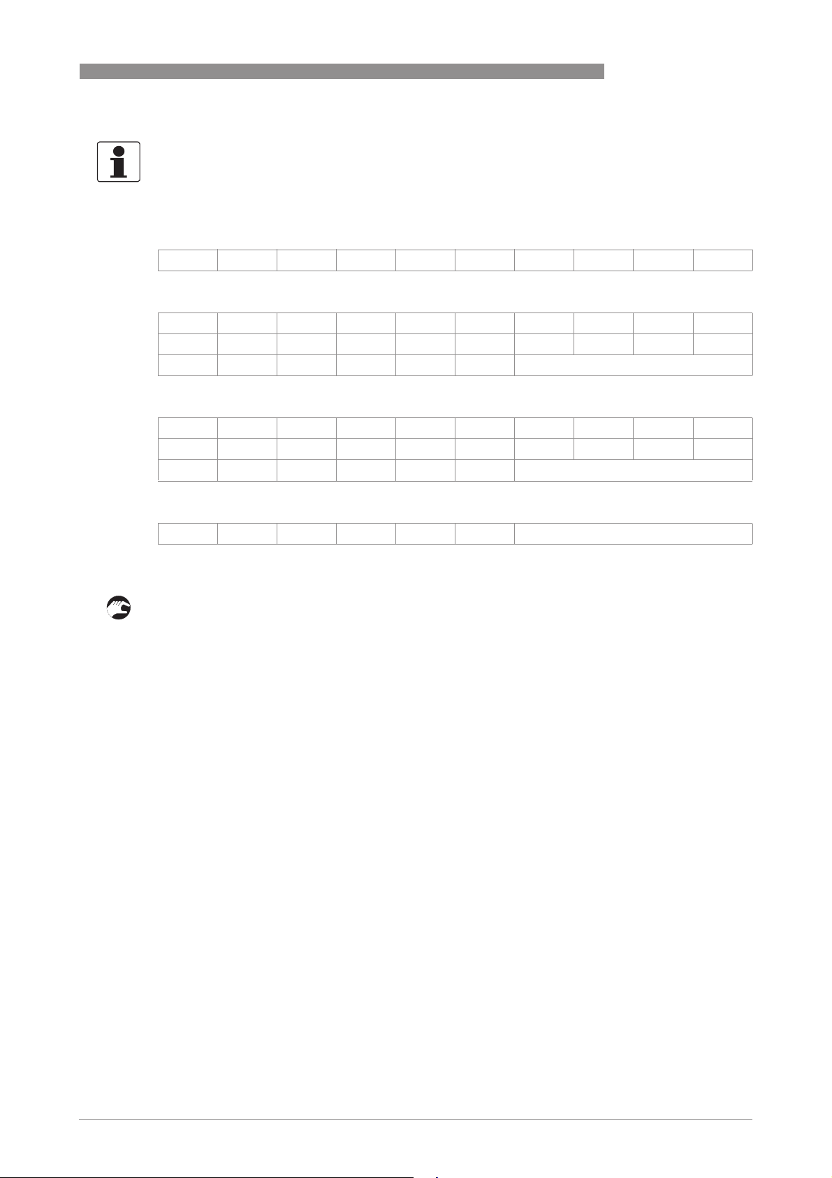
OPTIWAVE 7500 C
INFORMATION!
Values in menu items
Values in menu items
Values in menu itemsValues in menu items
If the digit is part of a custom unit name, then refer to the list of available characters that
follows:
Numbers
0 1 2 3 4 5 6 7 8 9
Lower case letters
a b c d e f g h i j
k l m n o p q r s t
u v w x y z
Upper case letters
A B C D E F G H I J
K L M N O P Q R S T
U V W X Y Z
OPERATION
6
Special characters
2 3
_ - / ....
6.3.5 How to save settings changed in program mode
• When you have changed parameters in all the necessary menu items, push [^^^^] to accept the
new parameter.
• Push [^^^^] again and again to go back to the "Save Configuration?" screen.
• The device will ask you to save or cancel your settings. Push [] or [] to make a selection
from Yes
Yes, No
No or Back
Back. Back
YesYes
NoNo
to "Yes" or No", push [^^^^] to accept (Yes) or reject (No) the new settings.
i If you push [^
mode.
^] when the screen is set to "Yes" or No", the display goes back to normal
^^
Back makes the display go back to Program mode. If this screen is set
BackBack
BackBack
www.krohne.com10/2016 - 4004375401 - MA OPTIWAVE 7500 R01 en
53
Page 54
6
OPERATION
6.3.6 Menu overview
Menu overview: A – Quick Setup
Normal Program
Menu A Submenus
> ^ ↓ ↑ > ^ ↓ ↑ > ^ ↓ ↑ > ^
A Quick Setup A1 Language
A2Tag
A3 Login
A4 Application
Assistant
A4.1 Standard Setup A4.1.1.1 Length Unit
A4.2 Empty
Spectrum /
A4.2.1 Record
Spectrum
OPTIWAVE 7500 C
A4.1.2.1 Tank Type
A4.1.2.2 Tank Height
A4.1.2.2 Stillwell Height
A4.1.2.3 Stillwell Diameter
A4.1.3.1 Current Out. 1 Var.
A4.1.3.2 0% Range
A4.1.3.3 100% Range
A4.1.3.4 Current Out. Range
A4.1.3.5 Error Function
A4.1.3.6 Error Delay
A4.2.1.1 Empty Spectrum Type
A4.2.1.2 Partial Distance
A4.2.1.3 Partial Distance
A4.2.1.4 Start Recording?
A4.2.1.5 Empty Spectrum
A4.2.1.6 Empty Spectrum
Graph
A4.2.1.7 Save Spectrum?
A4.2.1.8 Empty Spectrum
Enable
54
www.krohne.com 10/2016 - 4004375401 - MA OPTIWAVE 7500 R01 en
Page 55
OPTIWAVE 7500 C
OPERATION
Menu overview: B – Test
Normal Program
Menu B Submenus
> ^ ↓ ↑ > ^ ↓ ↑ > ^ ↓ ↑ > ^ ↓ ↑ >
B Test B1 Simulation B1.1 Set Value B1.1.1 Sensor Value
B1.1.2 Level
B1.1.3 Distance
B1.1.4 Reflection
B1.1.5 Level Lin.
B1.1.6 Volume
B1.1.7 Mass
B1.1.8 Distance Lin.
B1.1.9 Ullage Volume
B1.1.10 Ullage Mass
B1.2 Output B1.2.1 Current Output 1
B2 Actual
Values
B3 Power
Spectrum
B4 Corrected
Spectrum
B5 Empty
Spectrum
B2.1 Operating Time
B2.2 Time/Date
B2.3 Sensor Value
B2.4 Level
B2.5 Distance
B2.6 Reflection
B2.7 Level Lin.
B2.8 Volume
B2.9 Mass
B2.10 Distance Lin.
B2.11 Ullage Volume
B2.12 Ullage Mass
B2.13 Sensor Temp.
B2.14 Converter Temp.
B3.1 Request Spectrum
Pressure
B3.2 Power Spectrum
B4.1 Request Spectrum
B4.2 Corrected
Spectrum
B5.1 Request Spectrum
B5.2 Empty Spectrum
6
www.krohne.com10/2016 - 4004375401 - MA OPTIWAVE 7500 R01 en
55
Page 56
6
OPERATION
Menu overview: C – Full Setup
Normal Program
Menu C Submenus
> ^ ↓ ↑ > ^ ↓ ↑ > ^ ↓ ↑ > ^ ↓ ↑ >
OPTIWAVE 7500 C
C Setup C1 Install
Parameters
C Setup C2 Process C2.1 Tracking
C Setup C3 Conversion C3.1 Edit Table C3.1.1 Erase Table?
C1.1 Tank Type
C1.2 Tank Height
C1.3 Stillwell Height
C1.4 Stillwell
Diameter
C1.5 Blocking
Distance
C1.6 Time Constant
C1.7 Antenna Type
C1.8 Antenna
Extension
C1.9 Distance Piece
C1.10 Reference
Offset
C1.11 Tank Bottom
Offset
Velocity
C2.2 Epsilon R
Product
C2.3 Epsilon R Gas
C2.4 Measuring
Mode
C2.5 Overfill
Detection
C2.6 Overfill
Threshold
C2.7 Mult. Refl.
Enable
C2.8 Empty
Spectrum Enable
C2.9 Min Peak req.
C2.10 Min Plaus.
Window
C3.1.2 Select Conversion
C3.2 Input Table C3.2.2 Point
C3.2.4 Level
C3.2.5 Conv. Value
56
www.krohne.com 10/2016 - 4004375401 - MA OPTIWAVE 7500 R01 en
Page 57
OPTIWAVE 7500 C
OPERATION
Normal Program
Menu C Submenus
> ^ ↓ ↑ > ^ ↓ ↑ > ^ ↓ ↑ > ^ ↓ ↑ >
6
C Setup C4 Output C4.1 Current Output
1
C4.1.1 Current Out. 1 Var.
C4.1.2 0% Range
C4.1.3 100% Range
C4.1.4 Current Out. Range
C4.1.5 Error Function
C4.1.6 Error Delay
C4.1.7 Low Error Current
C4.1.8 High Error Current
C4.1.9.2 Trimming / 4mA
Trimming
C4.1.9.5 Trimming / 20mA
Trimming
www.krohne.com10/2016 - 4004375401 - MA OPTIWAVE 7500 R01 en
57
Page 58
6
OPERATION
Normal Program
Menu C Submenus
> ^ ↓ ↑ > ^ ↓ ↑ > ^ ↓ ↑ > ^ ↓ ↑ >
OPTIWAVE 7500 C
C Setup C5
Communication
C Setup C6 Display C6.1 Language
C5.1.2 HART C5.1.1Current Loop Mode
C6.2 Backlight
C6.3 Contrast
C5.1.2.1 Identification / Polling
Adress
C5.1.2.2 Identification / Tag
C5.1.2.3 Identification / Long
Tag
C5.1.2.4 Identification /
Manufacturer ID
C5.1.2.5 Identification / Device
Type
C5.1.2.6 Identification / Device
ID
C5.1.2.7 Identification /
Universal Revison
C5.1.2.8 Identification / Device
Revison
C5.1.2.9 Identification /
Software Revison
C5.1.2.10 Identification /
Hardware Revison
C5.1.3.1 Device Information /
Descriptor
C5.1.3.1 Device Information /
Message
C5.1.3.1 Device Information /
Date
C5.1.3.1 Device Information /
Cfg. Change Counter
C5.1.4.1 HART Variables /
Current Out. 1 Var.
C5.1.4.2 HART Variables / HART
sec./CO2 Var.
C5.1.4.3 HART Variables /
Tertiary Var.
C5.1.4.4 HART Variables /
Quarternary Var.
58
www.krohne.com 10/2016 - 4004375401 - MA OPTIWAVE 7500 R01 en
Page 59
OPTIWAVE 7500 C
OPERATION
Normal Program
Menu C Submenus
> ^ ↓ ↑ > ^ ↓ ↑ > ^ ↓ ↑ > ^ ↓ ↑ >
C6.4 1st Meas. page C6.4.1 Function
C6.4.2 1st Value Variable
C6.4.3 0% Range
C6.4.4 100% Range
C6.4.5 Format 1st Value
C6.4.6 2nd Value Variable
C6.4.7 Format 2nd Value
C6.4.8 3rd Value Variable
C6.4.9 Format 3rd Value
C6.5 2nd Meas. page C6.5.1 Function
C6.5.2 1st Value Variable
C6..3 0% Range
C6.5.4 100% Range
C6.5.5 Format 1st Value
C6.5.6 2nd Value Variable
C6.5.7 Format 2nd Value
C6.5.8 3rd Value Variable
C6.5.9 Format 3rd Value
C Setup C7 Device C7.1 Information C7.1.1 Tag
C7.1.2 Serial Number
C7.1.3 Device Name
C7.1.4 V Number
C7.1.5 Electronic Revision
C7.1.6 Software Revision
C7.1.7 Electronic serial No.
C7.1.8 Production Date
C7.1.9 Calibration Date
C7.1.10 SIL Mode
C7.1.11 Custody Transfer Mode
C7.1.12 WHG Mode
C7.1.13 API-2350 Mode
C7 Device C7.2 Security C7.2.1 Login
C7.2.2 Change Password
C7.2.3 Reset Passwords
C7.3 Errors C7.3.1 Message
C7.3.2.1 Error-Mapping /
Sensor: Information
C7.4 Real Time Clock C7.4.1 Set Time
C7.4.2 Set Time
6
www.krohne.com10/2016 - 4004375401 - MA OPTIWAVE 7500 R01 en
59
Page 60
6
OPERATION
Normal Program
Menu C Submenus
> ^ ↓ ↑ > ^ ↓ ↑ > ^ ↓ ↑ > ^ ↓ ↑ >
C7.5 Units C7.5.1 Length Unit
C7.5.2.1 Cst. Length / Text
C7.5.2.2 Cst. Length / Offset
C7.5.2.3 Cst. Length / Factor
C7.5.3 Volume
C7.5.4.1 Cst. Volume / Text
C7.5.4.2 Cst. Volume / Offset
C7.5.4.1 Cst. Volume / Factor
C7.5.5 Mass
C7.5.6.1 Cst. Mass / Text
C7.5.6.2 Cst. Mass / Offset
C7.5.6.3 Cst. Mass / Factor
C7.6 Factory Default C7.6.1 Reset to Fact. Def.?
OPTIWAVE 7500 C
6.3.7 Function description
A – Quick Setup menu
Menu
No.
A1 Language Make a selection to show the
A2 Tag You can see the TAG name here. The
A3 Login Enter the appropriate password here
A4 Application Assistant
A4 Application Assistant
A4 Application AssistantA4 Application Assistant
Function Function description Selection list Default
measurement data and settings in one
of the languages stored in in the
device.
Minimum security level to change the
Minimum security level to change the
Minimum security level to change the Minimum security level to change the
setting:
setting: User
setting:setting:
tag name can be a maximum of 8
characters long and it can have
numbers, upper-case and lower-case
letters and special characters. For
more data, , refer to
on page 50 (values in menu items).
Minimum security level to change the
Minimum security level to change the
Minimum security level to change the Minimum security level to change the
setting:
setting: Operator
setting:setting:
to change settings. If you do not enter
the password, you can only change
settings for the "user" security level.
For more data, refer to
Keypad functions
Protection of
the device settings (security levels)
page 47.
English, French, German,
Italian, Japanese, Chinese
(simplified), Portuguese,
Russian, Spanish, Czech, Polish,
Turkish
Refer to "Function description" 00000000
4-digit hexadecimal password Refer to
on
English
"Function
description
"
60
www.krohne.com 10/2016 - 4004375401 - MA OPTIWAVE 7500 R01 en
Page 61

OPTIWAVE 7500 C
OPERATION
6
Menu
Function Function description Selection list Default
No.
A4.1 Standard Setup This starts a quick set-up procedure
A4.2 Fixed and moving objects in the tank
applicable to most applications. You
can set the length unit, installation
specifications (tank type, tank height,
still well height, still well diameter
etc.) and current output specifications
(0% range, 1000% range, error function
etc.). For more data about the
functions, refer to Table C – Full Setup,
in this section. For more data about the
procedure, refer to
page 79.
Minimum security level to do the
Minimum security level to do the
Minimum security level to do the Minimum security level to do the
procedure:
procedure: Expert
procedure:procedure:
cause interference signals. Put them
through this filter to correctly measure
the tank contents. This menu item
starts a quick set-up procedure. We
recommend that the tank is empty or
only filled to the minimum level before
you do the procedure. We also
recommend that if you installed the
device on a tank that has equipment
with parts that move (e.g. agitators),
start the equipment. Set the Save
Spectrum?
Spectrum? step to "Yes", Empty
Spectrum? Spectrum?
Spectrum Enable
Spectrum Enable step to "Enable" at
Spectrum EnableSpectrum Enable
the end the procedure and set the Save
Configuration? screen to "Yes" to use
the data. For more data about the
procedure, refer to
recording
"How to make a filter to remove radar
signal interference" on page 87.
on page 82. Refer also to
Standard Setup
Save
Save Save
Empty
Empty Empty
Empty spectrum
on
Minimum security level to do the
Minimum security level to do the
Minimum security level to do the Minimum security level to do the
procedure:
procedure: Expert
procedure:procedure:
B – Test menu
Menu
No.
Function Function description Selection list Default
B1 Simulation
B1.1 Set Value
B1.1 Set Value
B1.1 Set ValueB1.1 Set Value
B1.1.2 Level This sets the device to a given test level
value. This procedure sends an output
signal that agrees with the test
reading. Output will change to the
selected value, independent of the
measurement data.
When you push [^^^^] to confirm the
value, the display shows the question
"Start Simulation?" Push [] or [] to
set the display to "Yes". Push [^^^^]again
to start the test.
Minimum security level to do the
Minimum security level to do the
Minimum security level to do the Minimum security level to do the
procedure:
procedure: User
procedure:procedure:
min-max:
-4900.0...+5100.0 m / -
1076...+16732 ft
+0 m
www.krohne.com10/2016 - 4004375401 - MA OPTIWAVE 7500 R01 en
61
Page 62

6
OPERATION
OPTIWAVE 7500 C
Menu
Function Function description Selection list Default
No.
B1.1.3 Distance This sets the device to a given test
B1.1.4 Reflection This sets the device to a given test
B1.1.5 Level Lin. This sets the device to a given test level
distance value. This procedure sends
an output signal that agrees with the
test reading. Output will change to the
selected value, independent of the
measurement data.
When you push [^^^^] to confirm the
value, the display shows the question
"Start Simulation?" Push [] or [] to
set the display to "Yes". Push [^^^^]again
to start the test.
Minimum security level to do the
Minimum security level to do the
Minimum security level to do the Minimum security level to do the
procedure:
procedure: User
procedure:procedure:
reflection value. This procedure sends
an output signal that agrees with the
test reading. Output will change to the
selected value, independent of the
measurement data.
When you push [^^^^] to confirm the
value, the display shows the question
"Start Simulation?" Push [] or [] to
set the display to "Yes". Push [^^^^]again
to start the test.
Minimum security level to do the
Minimum security level to do the
Minimum security level to do the Minimum security level to do the
procedure:
procedure: User
procedure:procedure:
value (linearized). This menu item is
only available if you set up a
linearization table in menu item C3.1
Edit Table
Edit Table. This procedure sends an
Edit TableEdit Table
output signal that agrees with the test
reading. Output will change to the
selected value, independent of the
measurement data.
C3.1
C3.1 C3.1
min-max:
-4900.0...+5100.0 m / -
1076...+16732 ft
min-max:
0...100%
min-max:
-4900.0...+5100.0 m / -
1076...+16732 ft
+20.0 m
0%
+0 m
When you push [^^^^] to confirm the
value, the display shows the question
"Start Simulation?" Push [] or [] to
set the display to "Yes". Push [^^^^]again
to start the test.
Minimum security level to do the
Minimum security level to do the
Minimum security level to do the Minimum security level to do the
procedure:
procedure: User
procedure:procedure:
B1.1.6 Volume This sets the device to a given test
volume value. This menu item is only
available if you set up a conversion
(volume) table in menu item C3.1 Edit
Table
Table. This procedure sends an output
TableTable
signal that agrees with the test
reading. Output will change to the
selected value, independent of the
measurement data.
When you push [^^^^] to confirm the
value, the display shows the question
"Start Simulation?" Push [] or [] to
set the display to "Yes". Push [^^^^]again
to start the test.
Minimum security level to do the
Minimum security level to do the
Minimum security level to do the Minimum security level to do the
procedure:
procedure: User
procedure:procedure:
C3.1 Edit
C3.1 Edit C3.1 Edit
min-max:
+06
0...1.00
+0 m³
m³
62
www.krohne.com 10/2016 - 4004375401 - MA OPTIWAVE 7500 R01 en
Page 63

OPTIWAVE 7500 C
OPERATION
6
Menu
Function Function description Selection list Default
No.
B1.1.7 Mass This sets the device to a given test
B1.1.8 Distance Lin. This sets the device to a given test
mass value. This menu item is only
available if you set up a conversion
(mass) table in menu item C3.1 Edit
Table
Table. This procedure sends an output
TableTable
signal that agrees with the test
reading. Output will change to the
selected value, independent of the
measurement data.
When you push [^^^^] to confirm the
value, the display shows the question
"Start Simulation?" Push [] or [] to
set the display to "Yes". Push [^^^^]again
to start the test.
Minimum security level to do the
Minimum security level to do the
Minimum security level to do the Minimum security level to do the
procedure:
procedure: User
procedure:procedure:
distance value (linearized). This menu
item is only available if you set up a
linearization table in menu item C3.1
Edit Table
Edit Table. This procedure sends an
Edit TableEdit Table
output signal that agrees with the test
reading. Output will change to the
selected value, independent of the
measurement data.
When you push [^^^^] to confirm the
value, the display shows the question
"Start Simulation?" Push [] or [] to
set the display to "Yes". Push [^^^^]again
to start the test.
C3.1 Edit
C3.1 Edit C3.1 Edit
C3.1
C3.1 C3.1
min-max:
0...10.000
min-max:
-4900.0...+5100.0 m
+09
kg
0kg
+0 m
Minimum security level to do the
Minimum security level to do the
Minimum security level to do the Minimum security level to do the
procedure:
procedure: User
procedure:procedure:
B1.1.9 Ullage Volume This sets the device to a given test
ullage volume value. This menu item is
only available if you set up a conversion
(volume) table in menu item C3.1 Edit
Table
Table. This procedure sends an output
TableTable
signal that agrees with the test
reading. Output will change to the
selected value, independent of the
measurement data.
When you push [^^^^], the display shows
the question "Start Simulation?" Push
[] or [] to set the display to "Yes".
Push [^^^^]again to start the test.
Minimum security level to do the
Minimum security level to do the
Minimum security level to do the Minimum security level to do the
procedure:
procedure: User
procedure:procedure:
C3.1 Edit
C3.1 Edit C3.1 Edit
min-max:
+06
0...1.00
1
m³
www.krohne.com10/2016 - 4004375401 - MA OPTIWAVE 7500 R01 en
63
Page 64

6
OPERATION
OPTIWAVE 7500 C
Menu
Function Function description Selection list Default
No.
B1.1.10 Ullage Mass This sets the device to a given test
B1.2 Output
B1.2 Output
B1.2 OutputB1.2 Output
B1.2.1 Current Output 1 This sets analogue output 1 to a test
ullage mass value. This menu item is
only available if you set up a conversion
(mass) table in menu item C3.1 Edit
Table
Table. This procedure sends an output
TableTable
signal that agrees with the test
reading. Output will change to the
selected value, independent of the
measurement data.
When you push [^^^^] to confirm the
value, the display shows the question
"Start Simulation?" Push [] or [] to
set the display to "Yes". Push [^^^^]again
to start the test.
Minimum security level to do the
Minimum security level to do the
Minimum security level to do the Minimum security level to do the
procedure:
procedure: User
procedure:procedure:
value [mA]. Output will change to the
selected value, independent of the
measured value.
When you push [^^^^] to confirm the
value, the display shows the question
"Start Simulation?" Push [] or [] to
set the display to "Yes". Push [^^^^]again
to start the test.
Minimum security level to do the
Minimum security level to do the
Minimum security level to do the Minimum security level to do the
procedure:
procedure: User
procedure:procedure:
C3.1 Edit
C3.1 Edit C3.1 Edit
min-max:
0...10.000
3.6...21.5 mA 21.5 mA
+09
kg
1
B2 Actual Values
B2.1 Operating Time
[s]
B2.4 Level This menu item shows the level
B2.5 Distance This menu item shows the distance
B2.6 Reflection This menu item shows the percentage
B2.7 Level Lin. This menu item shows the level
B2.8 Volume This menu item shows the volume
This is the total time that the device is
energized in seconds.
readings measured at this time. This
measurement data is shown with the
units set in menu C7.5 Units
readings measured at this time. This
measurement data is shown with the
units set in menu C7.5 Units
of the emitted radar signal which
makes a reflection on the surface of
the tank or silo contents and is
received by the device.
readings (linearized) measured at this
time. This measurement data is shown
with the units set in menu C7.5 Units
This menu item is only available if you
set up a linearization table in menu
item C3.1 Edit Table
C3.1 Edit Table.
C3.1 Edit TableC3.1 Edit Table
readings measured at this time. This
measurement data is shown with the
units set in menu C7.5 Units
menu item is only available if you set
up a conversion (volume) table in menu
item C3.1 Edit Table
C3.1 Edit Table.
C3.1 Edit TableC3.1 Edit Table
C7.5 Units.
C7.5 UnitsC7.5 Units
C7.5 Units.
C7.5 UnitsC7.5 Units
C7.5 Units.
C7.5 UnitsC7.5 Units
C7.5 Units. This
C7.5 UnitsC7.5 Units
Read only —
Read only —
Read only —
Read only —
Read only —
Read only —
64
www.krohne.com 10/2016 - 4004375401 - MA OPTIWAVE 7500 R01 en
Page 65

OPTIWAVE 7500 C
OPERATION
6
Menu
Function Function description Selection list Default
No.
B2.9 Mass This menu item shows the mass
B2.10 Distance Lin. This menu item shows the distance
B2.11 Ullage Volume This menu item shows the ullage
B2.12 Ullage Mass This menu item shows the ullage mass
B2.13 Sensor Temp. Temperature of the sensor (antenna)
B2.14 Converter Temp. Temperature of the converter
readings measured at this time. This
measurement data is shown with the
units set in menu C7.5 Units
menu item is only available if you set
up a conversion (mass) table in menu
item C3.1 Edit Table
C3.1 Edit Table.
C3.1 Edit TableC3.1 Edit Table
readings (linearized) measured at this
time. This measurement data is shown
with the units set in menu C7.5 Units
This menu item is only available if you
set up a linearization table in menu
item C3.1 Edit Table
C3.1 Edit Table.
C3.1 Edit TableC3.1 Edit Table
volume readings measured at this
time. This measurement data is shown
with the units set in menu C7.5 Units
This menu item is only available if you
set up a conversion (volume) table in
menu item C3.1 Edit Table
readings measured at this time. This
measurement data is shown with the
units set in menu C7.5 Units
menu item is only available if you set
up a conversion (mass) table in menu
item C3.1 Edit Table
C3.1 Edit Table.
C3.1 Edit TableC3.1 Edit Table
electronics block.
electronics block. Operation of display
can stop if the temperature is below 20°C/ -4°F or above +70°C / +158°F.
C7.5 Units. This
C7.5 UnitsC7.5 Units
C3.1 Edit Table.
C3.1 Edit TableC3.1 Edit Table
C7.5 Units. This
C7.5 UnitsC7.5 Units
C7.5 Units.
C7.5 UnitsC7.5 Units
C7.5 Units.
C7.5 UnitsC7.5 Units
Read only —
Read only —
Read only —
Read only —
Read only —
Read only —
B3 Power Spectrum
B3.2 Power Spectrum This menu item shows the uncorrected
B4 Corrected Spectrum
B4.2 Corrected
Spectrum
B5 Empty Spectrum
spectra of the radar signal which
makes a reflection on the surface of
the tank or silo contents and is
received by the device. This data is
shown as a graph of the percentage of
the full-scale signal against distance.
This menu item shows the corrected
spectra of the radar signal which
makes a reflection on the surface of
the tank or silo contents and is
received by the device. This is the
result of the spectra from an empty
tank or silo subtracted from the power
spectra. This data is shown as a graph
of the percentage of the full-scale
signal against distance.
Read only —
Read only —
www.krohne.com10/2016 - 4004375401 - MA OPTIWAVE 7500 R01 en
65
Page 66

6
OPERATION
OPTIWAVE 7500 C
Menu
Function Function description Selection list Default
No.
B5.2 Empty Spectrurm This menu item shows the spectra of
1 The maximum value in the conversion table
the radar signal which makes a
reflection at the bottom of an empty
tank (or a partially full tank, if it is not
possible to remove all the tank
contents). This data is shown as a
graph of the percentage of the fullscale signal against distance.
C – Full Setup menu
Menu
No.
Function Function description Selection list Default
C1 Install Parameters
C1.1 Tank Type The conditions in which the device is used. If
C1.2 Tank Height Tank height is the distance from the flange
the surface of the product is flat, select
"Storage". If the surface of the product is
disturbed, select "Process". If the surface of
the product is agitated with vortexes and
foam, select "Agitator". If the device is
installed in a still well, select "Still Well".
Minimum security level to change the
Minimum security level to change the
Minimum security level to change the Minimum security level to change the
setting:
setting: Expert
setting:setting:
face/thread stop of the process connection
to the tank bottom. If you use the device for
an LPR (open-air) application, this value is
the maximum distance that the device must
measure (the measuring range). If you set
menu item C1.1 Tank Height to "Still Well",
this menu item is not available.
Read only —
Agitator, Still Well,
Process, Storage
min-max:
0.0...100.00
0...196.85 ft
+03
mm /
Process
10000 mm /
32.808 ft
Minimum security level to change the
Minimum security level to change the
Minimum security level to change the Minimum security level to change the
setting:
setting: Expert
setting:setting:
C1.3 Still Well Height The height of the still well. This menu item
C1.4 Still Well
Diameter
C1.5 Blocking
Distance
is available if you set "Still Well" in menu
item C.1.1 Tank Type.
Minimum security level to change the
Minimum security level to change the
Minimum security level to change the Minimum security level to change the
setting:
setting: Expert
setting:setting:
The inner diameter of the still well. This
menu item is available if you set "Still Well"
in menu item C.1.1 Tank Type.
Minimum security level to change the
Minimum security level to change the
Minimum security level to change the Minimum security level to change the
setting:
setting: Expert
setting:setting:
The distance from the flange facing or the
thread stop to the top limit of the measuring
range (a zone given by the user where it is
not possible to measure). We recommend a
minimum blocking distance of 100 mm / 4¨
below the bottom of the antenna. If the
distance is less than the blocking distance,
the device continues to show the blocking
distance on the display screen.
Minimum security level to change the
Minimum security level to change the
Minimum security level to change the Minimum security level to change the
setting:
setting: Expert
setting:setting:
min-max:
500.0...100.00
1.6404...328.08 ft
min-max:
22.0...999.0 mm / 866.14
03
...39.331¨
min-max:
75.0...5000.0 mm /
2.9528...196.85¨
+03
mm /
10000 mm /
32.808 ft
100 mm /
-
3.937¨
500 mm /
19.685¨
66
www.krohne.com 10/2016 - 4004375401 - MA OPTIWAVE 7500 R01 en
Page 67

OPTIWAVE 7500 C
OPERATION
6
Menu
Function Function description Selection list Default
No.
C1.6 Time Constant Using this function, the device processes
C1.7 Antenna Type The type of antenna attached to the device. If
C1.8 Antenna
Extension
C1.9 Distance piece Optional distance piece between the
several measurement readings to filter out
disturbances. Increasing the time constant
will smoothen the integrated readings,
decreasing will roughen the readings. s =
seconds.
Minimum security level to change the
Minimum security level to change the
Minimum security level to change the Minimum security level to change the
setting:
setting: Expert
setting:setting:
you change the antenna, this setting will
have an effect on C1.2 Tank Height and C1.5
Blocking Distance. For more data, <Antenna
Selection>.
Minimum security level to change the
Minimum security level to change the
Minimum security level to change the Minimum security level to change the
setting:
setting: Expert
setting:setting:
Optional antenna extension. These are
attached between the flange and the
antenna. Each segment is 105 mm / 4.1¨
long.
Minimum security level to change the
Minimum security level to change the
Minimum security level to change the Minimum security level to change the
setting:
setting: Expert
setting:setting:
converter and the process connection. This
is for the high-temperature version of the
device. Each segment is 105 mm / 4.1¨ long.
min-max:
0....100.0 sec (seconds)
Metallic Horn (DN40),
Metallic Horn (DN50),
Metallic Horn (DN65),
Metallic Horn,(DN80),
Metallic Horn (DN100),
Metallic Horn (DN200),
Drop (PP, DN80), Drop
(PP, DN150); Drop (PTFE,
DN80), Drop (PTFE,
DN150); Drop (PEEK,
DN80), Drop (PEEK,
DN150) Hygienic (PEEK,
DN50)
min-max:
0.0…10000 mm /
0.0...393.7¨
min-max:
0.0…2000 mm /
0.0...78.74¨
0s
Metallic Horn
(DN100)
0mm/0¨
0mm/ 0¨
C1.10 Reference
Offset
C1.11 Tank Bottom
Offset
C2 Process
C2.1 Tracking
Velocity
Minimum security level to change the
Minimum security level to change the
Minimum security level to change the Minimum security level to change the
setting:
setting: Expert
setting:setting:
Offset relating to a reference location
(distance). This value is positive when the
reference location is above the device flange
face and negative if below. For more
data,<Distance>.
Minimum security level to change the
Minimum security level to change the
Minimum security level to change the Minimum security level to change the
setting:
setting: Expert
setting:setting:
Offset relating to a reference location
(level). The device reference point for this
parameter is the bottom of the tank (set in
menu item C1.2 Tank Height). This value is
positive when the reference location is
below the tank bottom and negative if above.
For more data,<Level>.
Minimum security level to change the
Minimum security level to change the
Minimum security level to change the Minimum security level to change the
setting:
setting: Expert
setting:setting:
This menu item sets the maximum rate of
change of level in metres per minute or feet
per minute. The measured value cannot
change faster than the tracing velocity.
Minimum security level to change the
Minimum security level to change the
Minimum security level to change the Minimum security level to change the
setting:
setting: Expert
setting:setting:
min-max:
-5000.0+0…+5000.0 m / -
16404...+164404 ft
min-max:
-
5000.0+0…+5000.0 mm /
-16404...+164404 ft
min-max:
+03
1.2
3.937
…60.0
+03
...196.85 ft
+06
m/min /
0m/ 0ft
0m/ 0ft
-
60.0
03
m 196.85
03
ft/min
-
www.krohne.com10/2016 - 4004375401 - MA OPTIWAVE 7500 R01 en
67
Page 68

6
OPERATION
OPTIWAVE 7500 C
Menu
Function Function description Selection list Default
No.
C2.2 Epsilon R
Product
C2.3 Epsilon R Gas A major parameter for radar level
C2.4 Measuring
Mode
The device automatically calculates the
level based on the product εr. If you select
"TBF Full" or "TBF Auto" in menu item C2.4
Measuring Mode, you can change this value
manually to adjust readings.
Minimum security level to change the
Minimum security level to change the
Minimum security level to change the Minimum security level to change the
setting:
setting: Expert
setting:setting:
measurement devices. If the gas is not air,
set the εrvalue to the εr value of the gas.
Minimum security level to change the
Minimum security level to change the
Minimum security level to change the Minimum security level to change the
setting:
setting: Expert
setting:setting:
The device uses the dielectric constant (εr)
of the tank contents to monitor level. In
"Direct" mode (if the dielectric constant is
high), the level signal is a reflection on the
surface of the tank contents. If the dielectric
constant is low, the device uses "TBF Auto"
or "TBF Full" mode. The device in "TBF"
mode uses the radar reflection on the
bottom of the tank (the signal goes through
the tank contents). The tank must have a flat
bottom for the device to operate correctly in
TBF mode. This menu item is set by default
to "Direct" for tank contents with an ε
is very low (<1.6), use "TBF Full". If εr is
If ε
r
low (εr = 1.5...1.7), use "TBF Auto" mode.
"TBF Auto" is an automatic mode that lets
the device make a selection between
"Direct" mode and "TBF" mode. If you use
"TBF Full" or "TBF Auto", enter the
dielectric constant in menu item C2.2
Epsilon R Product. Refer also to "Measuring
principle" on page 98.
>1.8.
r
1.1...20 2.0
1.0...20 1.0
Direct, TBF Partial, TBF
Full
Direct
C2.5 Overfill
Detection
C2.6 Overfill
Threshold
Minimum security level to change the
Minimum security level to change the
Minimum security level to change the Minimum security level to change the
setting:
setting: Expert
setting:setting:
If this function is in operation, the device will
monitor the level even if it is in the blocking
distance. The output shown on the display
screen stays fixed at the blocking distance,
but an error message will warn the user
that the tank is too full.
Minimum security level to change the
Minimum security level to change the
Minimum security level to change the Minimum security level to change the
setting:
setting: Expert
setting:setting:
If you have set 2.5 Overfill Detection to
"Enabled", this menu item will be available.
If the device cannot easily measure in the
blocking distance (see menu item C1.5),
then you can change the overfill threshold.
This value is a percentage of the radar
signal amplitude. To enter the correct value,
we recommend that you speak or write to
your supplier.
Minimum security level to change the
Minimum security level to change the
Minimum security level to change the Minimum security level to change the
setting:
setting: Expert
setting:setting:
Disabled, Enabled Disabled
min-max:
0.0...100.0%
9.6602%
68
www.krohne.com 10/2016 - 4004375401 - MA OPTIWAVE 7500 R01 en
Page 69

OPTIWAVE 7500 C
OPERATION
6
Menu
Function Function description Selection list Default
No.
C2.7 Mult. Refl.
C2.8 Empty
Enable
Spectrum
Enable
Multiple reflections will cause the device to
display smaller level readings. Installation
of the device on a manhole or at the centre
of a dome roof, and high dielectric products
(εr > 5) can cause multiple reflections. A
very calm surface or a tank with a small
convex or flat roof can also cause multiple
reflections.
If this function is in operation, the device
looks for the first signal peak below the
process connection. This signal peak is then
used to measure the level of the tank
contents. If this function is not in operation,
the device looks for the largest signal below
the process connection.
Minimum security level to change the
Minimum security level to change the
Minimum security level to change the Minimum security level to change the
setting:
setting: Expert
setting:setting:
This function starts and stops the
interference signal filter. Interference
signals are the result of fixed and moving
obstacles inside the tank. If you must do a
spectrum analysis, record an empty
spectrum first. Do the "Empty Spectrum"
procedure (menu A4.2) in the Quick Setup
menu.
Minimum security level to change the
Minimum security level to change the
Minimum security level to change the Minimum security level to change the
setting:
setting: Expert
setting:setting:
Disabled, Enabled Disabled
Disabled, Enabled Disabled
C3 Conversion
C3.1 Edit Table
C3.1 Edit Table
C3.1 Edit TableC3.1 Edit Table
C3.1.1 Erase Table? Before you can make a conversion table, you
C3.1.2 Select
C3.2 Input Table
C3.2 Input Table
C3.2 Input TableC3.2 Input Table
C3.2.2 Point This adds a point on the conversion table.
Conversion
must delete the data that is stored in the
device at this time. If you set this menu item
to "No" you will go back to menu C3.1. If you
set it to "Yes", you will go to menu item
C3.1.2 Select Conversion.
Minimum security level to change the
Minimum security level to change the
Minimum security level to change the Minimum security level to change the
setting:
setting: Expert
setting:setting:
If you must make a volume conversion table,
set this menu item to "Volume". If you must
make a mass conversion table, set this
menu item to "Mass". If you must make a
linearization table to make sure that the
readings always agree with reference
measurements, set this menu item to
"Linearization".
Minimum security level to change the
Minimum security level to change the
Minimum security level to change the Minimum security level to change the
setting:
setting: Expert
setting:setting:
Each time you enter this menu item, this
number will automatically increment by 1
point. If it is necessary to change the data
for a point, change the point number. When
you push [^^^^], you go to menu item C3.2.4
Level.
Yes, No No
Volume, Mass,
Linearization
min-max:
001...050
Volume
001
Minimum security level to do the procedure:
Minimum security level to do the procedure:
Minimum security level to do the procedure:Minimum security level to do the procedure:
Expert
www.krohne.com10/2016 - 4004375401 - MA OPTIWAVE 7500 R01 en
69
Page 70

6
OPERATION
OPTIWAVE 7500 C
Menu
Function Function description Selection list Default
No.
C3.2.4 Level Enter the level value for the point given in
C3.2.5 Conv. Value Enter the conversion value (volume, mass or
C3.2.2. Push [^^^^] to confirm the level value
and go to C3.2.5 Conv. Value.
Minimum security level to do the procedure:
Minimum security level to do the procedure:
Minimum security level to do the procedure:Minimum security level to do the procedure:
Expert
linearization) for the point given in C3.2.2.
Push [^^^^] to confirm the conversion value
and go back to menu C3.2.
Minimum security level to do the procedure:
Minimum security level to do the procedure:
Minimum security level to do the procedure:Minimum security level to do the procedure:
Expert
C4 Output
C4.1 Current Output 1
C4.1 Current Output 1
C4.1 Current Output 1C4.1 Current Output 1
C4.1.1 Current Out. 1
Var.
C4.1.2 0% Range Give a measurement value to 0% output
Make a selection from the available output
functions to scale the current output values.
This is not shown in the normal mode.
Minimum security level to change the
Minimum security level to change the
Minimum security level to change the Minimum security level to change the
setting:
setting: Expert
setting:setting:
(refer also to C4.1.1 Current Out. 1 Var for
the output function). This is the minimum
loop current (this does not include the error
current). The parameter set in menu item
C.4.1.4 Current Out. Range
C.4.1.4 Current Out. Range has an effect on
C.4.1.4 Current Out. RangeC.4.1.4 Current Out. Range
this current value.
min-max:
0.0...100.0
+03
mm /
0.0...3937.0¨
min-max:
Volume:
0.0...100.0
0.0...26.417
Mass: 0.0...100.0
0.0...220.46
Linearization:
0.0...100.0
0.0...3.937
+09
+12
+12
+12
+09
¨
m³ /
gal
+09
lb
mm /
kg /
Level, Sensor Value,
Reflection, Lin. Distance,
Lin. Level, Distance
min-max:
+06
-4.9
192.91
...+5.1
+03
...+200.79
+06
mm / -
+03
¨
0.0 mm / 0.0¨
Volume:0.0 m³
/ 0.0 gal
Mass:0.0 kg /
0.0 lb
Linearization:
0.0 mm / 0.0¨
Distance
0.0 mm
Minimum security level to change the
Minimum security level to change the
Minimum security level to change the Minimum security level to change the
setting:
setting: Expert
setting:setting:
C4.1.3 100% Range Give a measurement value to 100% output
(refer also to C4.1.1 Current Out. 1 Var for
the output function). This is the maximum
loop current (this does not include the error
current). The parameter set in menu item
C.4.1.4 Current Out. Range
C.4.1.4 Current Out. Range has an effect on
C.4.1.4 Current Out. RangeC.4.1.4 Current Out. Range
this current value.
Minimum security level to change the
Minimum security level to change the
Minimum security level to change the Minimum security level to change the
setting:
setting: Expert
setting:setting:
C4.1.4 Current Out.
Range
This menu item sets the limits of the output
current range to 1 of 4 available options:
standard limits (4...20 mA), NAMUR NE 43compliant limits (3.8...20.5 mA), reversed
standard limits and reversed NAMUR NE
43-compliant limits. You use standard limits
when you want the 0% output to be 3.8 or
4 mA and the 100% output to be 20 mA or
20.5m A. You use reversed limits when you
want the 0% output to be to be 20 mA or
20.5 mA and 100% output to be 3.8 mA or
4mA.
Minimum security level to change the
Minimum security level to change the
Minimum security level to change the Minimum security level to change the
setting:
setting: Expert
setting:setting:
min-max:
+06
-4.9
192.91
...+5.1
+03
...+200.79
+06
mm / -
+03
¨
4-20 mA, 3.8-20.5 mA
(NAMUR), 4-20 mA
(reversed), 3.8-20.5 mA
(reversed)
10000 mm
4-20 mA
70
www.krohne.com 10/2016 - 4004375401 - MA OPTIWAVE 7500 R01 en
Page 71

OPTIWAVE 7500 C
OPERATION
6
Menu
Function Function description Selection list Default
No.
C4.1.5 Error Function This sets the behaviour of current output 1 if
C4.1.7 Low Error
Current
C4.1.8 High Error
Current
an error occurs. If this menu item is set to
"Off", no signal is given (this parameter is
not available if menu item C4.1.4 is set to
"3.8-20.5 mA" (NAMUR) or "3.8-20.5 mA
(reversed)"). If this menu item is set to
"Hold", the output current stays at the value
where the error occurred (this parameter is
not available if menu item C4.1.4 is set to
"3.8-20.5 mA" (NAMUR) or "3.8-20.5 mA
(reversed)"). If this menu item is set to
"Low", the output current changes to 3.5 mA
(default value) if an error occurs. If this
menu item is set to "High", the output
current changes to 21.5 mA (default value) if
an error occurs.
Minimum security level to change the
Minimum security level to change the
Minimum security level to change the Minimum security level to change the
setting:
setting: Expert
setting:setting:
This menu item is available if C4.1.5 Error
Function is set to "Low". You can change the
value to which the current output will
change if an error occurs.
Minimum security level to change the
Minimum security level to change the
Minimum security level to change the Minimum security level to change the
setting:
setting: Expert
setting:setting:
This menu item is available if C4.1.5 Error
Function is set to "High". You can change
the value to which the current output will
change if an error occurs.
Off, Low, High, Hold Low
min-max:
3.5...3.6 mA
min-max:
21.0...21.5 mA
3.5 mA
21.5 mA
Minimum security level to change the
Minimum security level to change the
Minimum security level to change the Minimum security level to change the
setting:
setting: Expert
setting:setting:
C4.1.9 Trimming
C4.1.9.1 4mA Trimming Use this menu item if the current output of
C4.1.9.2 20mA Trimming Use this menu item if the current output of
the device is set to 4 mA, but the measured
loop current is not 4 mA. Enter the
measured value.
Minimum security level to change the
Minimum security level to change the
Minimum security level to change the Minimum security level to change the
setting:
setting: Expert
setting:setting:
the device is set to 20 mA, but the measured
loop current is not 20 mA. Enter the
measured value.
Minimum security level to change the
Minimum security level to change the
Minimum security level to change the Minimum security level to change the
setting:
setting: Expert
setting:setting:
C5 Communication
C5.1 HART
C5.1 HART
C5.1 HARTC5.1 HART
C5.1.1 Current Loop
Mode
C5.1.2 Identification
Set this menu item to "On" if the "Primary
Variable" for current output 1 must also be
transmitted as a 4…20 mA signal. If this
menu item is set to "Off', this stops the
4…20 mA signal and starts HART® multidrop mode.
Minimum security level to change the
Minimum security level to change the
Minimum security level to change the Minimum security level to change the
setting:
setting: Expert
setting:setting:
min-max:
0.0...25.0 mA
min-max:
0.0...25.0 mA
On, Off On
4mA
20 mA
www.krohne.com10/2016 - 4004375401 - MA OPTIWAVE 7500 R01 en
71
Page 72

6
OPERATION
OPTIWAVE 7500 C
Menu
Function Function description Selection list Default
No.
C5.1.2.1 Polling Address A polling address more than 0 will start
C5.1.2.2 Tag Use this menu item to change the Tag name.
C5.1.2.3 Long Tag Use this menu item to change the long Tag
C5.1.2.4 Manufacturer ID This is the manfacturer ID number given to
C5.1.2.5 Device Type This is the device type number given to the
C5.1.2.6 Device ID This is the device ID number given to the
C5.1.2.7 Universal
Revision
C5.1.2.8 Device Revision This is the revision number for the HART®
C5.1.2.9 Software
Revision
C5.1.2.10Hardware
Revision
C5.1.3 Device Information
C5.1.3.1 Descriptor You can give a short description (16
HART® multidrop mode. If you start HART®
multidrop mode, the current output stays
constant at 4 mA.
Minimum security level to change the
Minimum security level to change the
Minimum security level to change the Minimum security level to change the
setting:
setting: Operator
setting:setting:
It can have a maximum of 8 characters. For
more data about the characters available,
refer to
,(values in menu items).
Minimum security level to change the
Minimum security level to change the
Minimum security level to change the Minimum security level to change the
setting:
setting: Operator
setting:setting:
name. It can have a maximum of 32
characters. For more data about the
characters available, refer to
functions
items).
Minimum security level to change the
Minimum security level to change the
Minimum security level to change the Minimum security level to change the
setting:
setting: Operator
setting:setting:
the supplier by the HART Foundation.
supplier by the HART Foundation.
supplier by the HART Foundation. This
shows that the HART Foundation registered
the HART® device description (DD) file.
This is the version of the HART protocol
used by the device.
device description.
This is the revision number for the device
software.
This is the revision number for the device
hardware.
characters maximum) of the device in this
menu item.
Keypad functions
on page 50
Keypad
on page 50 ,(values in menu
000...063 0
— TANK01
— —
Read Only —
Read Only —
Read Only —
Read Only —
Read Only —
Read Only —
Read Only —
— —
Minimum security level to change the
Minimum security level to change the
Minimum security level to change the Minimum security level to change the
setting:
setting: Operator
setting:setting:
C5.1.3.2 Message You can give more data in this menu item
C5.1.3.3 Date You can enter the date in this menu item
C5.1.3.4 Cfg. Change
Counter
C5.1.4 HART Variables
72
(32 characters maximum).
Minimum security level to change the
Minimum security level to change the
Minimum security level to change the Minimum security level to change the
setting:
setting: Expert
setting:setting:
(Format: Year-Month-Day / YYYY-MM-DD)
This function counts the number of changes
to the HART® device settings
www.krohne.com 10/2016 - 4004375401 - MA OPTIWAVE 7500 R01 en
— —
— 2014-01-01
Read Only —
Page 73

OPTIWAVE 7500 C
OPERATION
6
Menu
Function Function description Selection list Default
No.
C5.1.4.1 Current Out. 1
Var.
C5.1.4.2 HART/sec./CO2
Var.
C5.1.4.2 Tertiary Var. This is the third measurement type shown
C5.1.4.2 Quaternary Var. This is the fourth measurement type shown
C6 Display
C6.1 Language Data can be shown in one of the languages
C6.2 Backlight If you set this menu item to "Enabled", a
This is the first measurement type shown on
HART® controllers. Make a selection from
the list.
Minimum security level to change the
Minimum security level to change the
Minimum security level to change the Minimum security level to change the
setting:
setting: Expert
setting:setting:
This is the second measurement type shown
on HART® controllers. Make a selection
from the list.
Minimum security level to change the
Minimum security level to change the
Minimum security level to change the Minimum security level to change the
setting:
setting: Expert
setting:setting:
on HART® controllers. Make a selection
from the list.
Minimum security level to change the
Minimum security level to change the
Minimum security level to change the Minimum security level to change the
setting:
setting: Operator
setting:setting:
on HART® controllers. Make a selection
from the list.
Minimum security level to change the
Minimum security level to change the
Minimum security level to change the Minimum security level to change the
setting:
setting: Operator
setting:setting:
stored in the device. Make a selection from
the list.
Minimum security level to change the
Minimum security level to change the
Minimum security level to change the Minimum security level to change the
setting:
setting: User
setting:setting:
light comes on when you push a buton on
the display keypad and if the loop current is
more than 6 mA.
Distance, Level, Sensor
Value, Reflection
Distance, Level, Sensor
Value, Reflection
Distance, Level, Sensor
Value, Reflection
Distance, Level, Sensor
Value, Reflection
English, German, French,
Italian Portuguese,
Spanish, Czech, Polish,
Chinese (simplified),
Japanese, Russian,
Turkish
Disabled, Enabled Disabled
Distance
Level
Reflection
Sensor Value
English
Minimum security level to change the
Minimum security level to change the
Minimum security level to change the Minimum security level to change the
setting:
setting: User
setting:setting:
C6.3 Contrast The contrast control for the display screen.
C6.4 1st Meas. Page
C6.4 1st Meas. Page
C6.4 1st Meas. PageC6.4 1st Meas. Page
C6.4.1 Function This menu item changes the configuration
C6.4.2 1st Value
C6.4.3 0% Range This is the 0% value given to the bar graph
Variable
You can select a shade of grey between light
grey (-10) and black (+10).
Minimum security level to change the
Minimum security level to change the
Minimum security level to change the Minimum security level to change the
setting:
setting: User
setting:setting:
of data shown on the display screen in
normal mode. There are two measurement
pages available to show readings in normal
mode. This setting is for the first page.
Minimum security level to change the
Minimum security level to change the
Minimum security level to change the Minimum security level to change the
setting:
setting: User
setting:setting:
This changes the measurement type of the
first value on the measurement page.
indicator in normal mode. The range is
related to the measurement type set in
C6.4.2 1st Value Variable. This menu item is
only available if you set C6.4.1 Function to
"One Value & Bar" or "Two Values & Bar".
min-max:
-10...+10
One Value, One Value &
Bar, Two Values, Two
Values & Bar, Three
Values
Distance, Level,
Reflection, Sensor Value
Refer to "Function
description".
0
One Value &
Bar
Distance
Refer to
"Function
description".
www.krohne.com10/2016 - 4004375401 - MA OPTIWAVE 7500 R01 en
73
Page 74

6
OPERATION
OPTIWAVE 7500 C
Menu
Function Function description Selection list Default
No.
C6.4.4 100% Range This is the 100% value given to the bar graph
C6.4.5 Format 1st
Value
C6.4.6 2nd Value
Variable
C6.4.7 Format 2nd
Value
indicator in normal mode. The range is
related to the measurement type set in
C6.4.2 1st Value Variable. This menu item is
only available if you set C6.4.1 Function to
"One Value & Bar" or "Two Values & Bar".
Minimum security level to change the
Minimum security level to change the
Minimum security level to change the Minimum security level to change the
setting:
setting: User
setting:setting:
You can change the number of decimal
places that are shown for the first value on
the measurement page in normal mode. For
example, if you set this menu item to "X.XX",
the value shown will be corrected to 2
decimal places. If you set this menu item to
"Automatic", the device will adjust the
number of decimal places automatically.
Minimum security level to change the
Minimum security level to change the
Minimum security level to change the Minimum security level to change the
setting:
setting: User
setting:setting:
This changes the measurement type of the
second value on the measurement page.
This menu item is only available if you set
C6.4.1 Function to "Two Values", "Two
Values & Bar" or "Three Values".
Minimum security level to change the
Minimum security level to change the
Minimum security level to change the Minimum security level to change the
setting:
setting: User
setting:setting:
You can change the number of decimal
places that are shown for the second value
on the measurement page in normal mode.
For example, if you set this menu item to
"X.XX", the value shown will be corrected to
2 decimal places. If you set this menu item
to "Automatic", the device will adjust the
number of decimal places automatically.
Refer to "Function
description".
X, X.X, X.XX, X.XXX,
X.XXXX, X.XXXXX,
X.XXXXXXX, Automatic
Distance, Level,
Reflection, Sensor Value
X, X.X, X.XX, X.XXX,
X.XXXX, X.XXXXX,
X.XXXXXXX, Automatic
Refer to
"Function
description".
X.XXX
Level
X.XXX
C6.4.8 3rd Value
C6.4.9 Format 3rd
C6.5 2nd Meas. Page
C6.5 2nd Meas. Page
C6.5 2nd Meas. PageC6.5 2nd Meas. Page
Variable
Value
Minimum security level to change the
Minimum security level to change the
Minimum security level to change the Minimum security level to change the
setting:
setting: User
setting:setting:
This changes the measurement type of the
third value on the measurement page. This
menu item is only available if you set C6.4.1
Function to "Three Values".
Minimum security level to change the
Minimum security level to change the
Minimum security level to change the Minimum security level to change the
setting:
setting: User
setting:setting:
You can change the number of decimal
places that are shown for the second value
on the measurement page in normal mode.
For example, if you set this menu item to
"X.XX", the value shown will be corrected to
2 decimal places. If you set this menu item
to "Automatic", the device will adjust the
number of decimal places automatically.
Minimum security level to change the
Minimum security level to change the
Minimum security level to change the Minimum security level to change the
setting:
setting: User
setting:setting:
Distance, Level,
Reflection, Sensor Value
X, X.X, X.XX, X.XXX,
X.XXXX, X.XXXXX,
X.XXXXXXX, Automatic
Reflection
X.XXX
74
www.krohne.com 10/2016 - 4004375401 - MA OPTIWAVE 7500 R01 en
Page 75

OPTIWAVE 7500 C
OPERATION
6
Menu
Function Function description Selection list Default
No.
C6.5.1 Function This menu item changes the configuration
C6.5.2 1st Value
Variable
C6.5.3 0% Range This is the 0% value given to the bar graph
C6.5.4 100% Range This is the 100% value given to the bar graph
of data shown on the display screen in
normal mode. There are two measurement
pages available to show readings in normal
mode. This setting is for the second page.
Minimum security level to change the
Minimum security level to change the
Minimum security level to change the Minimum security level to change the
setting:
setting: User
setting:setting:
This changes the measurement type of the
first value on the measurement page.
Minimum security level to change the
Minimum security level to change the
Minimum security level to change the Minimum security level to change the
setting:
setting: User
setting:setting:
indicator in normal mode. The range is
related to the measurement type set in
C6.4.2 1st Value Variable. This menu item is
only available if you set C6.4.1 Function to
"One Value & Bar" or "Two Values & Bar".
Minimum security level to change the
Minimum security level to change the
Minimum security level to change the Minimum security level to change the
setting:
setting: User
setting:setting:
indicator in normal mode. The range is
related to the measurement type set in
C6.4.2 1st Value Variable. This menu item is
only available if you set C6.4.1 Function to
"One Value & Bar" or "Two Values & Bar".
One Value, One Value &
Bar, Two Values, Two
Values & Bar, Three
Values
Distance, Level,
Reflection, Sensor Value
Refer to "Function
description".
Refer to "Function
description".
Three Values
Distance
Refer to
"Function
description".
Refer to
"Function
description".
C6.5.5 Format 1st
Value
C6.5.6 2nd Value
Variable
C6.5.7 Format 2nd
Value
Minimum security level to change the
Minimum security level to change the
Minimum security level to change the Minimum security level to change the
setting:
setting: User
setting:setting:
You can change the number of decimal
places that are shown for the first value on
the measurement page in normal mode. For
example, if you set this menu item to "X.XX",
the value shown will be corrected to 2
decimal places. If you set this menu item to
"Automatic", the device will adjust the
number of decimal places automatically.
Minimum security level to change the
Minimum security level to change the
Minimum security level to change the Minimum security level to change the
setting:
setting: User
setting:setting:
This changes the measurement type of the
second value on the measurement page.
This menu item is only available if you set
C6.4.1 Function to "Two Values", "Two
Values & Bar" or "Three Values".
Minimum security level to change the
Minimum security level to change the
Minimum security level to change the Minimum security level to change the
setting:
setting: User
setting:setting:
You can change the number of decimal
places that are shown for the second value
on the measurement page in normal mode.
For example, if you set this menu item to
"X.XX", the value shown will be corrected to
2 decimal places. If you set this menu item
to "Automatic", the device will adjust the
number of decimal places automatically.
Minimum security level to change the
Minimum security level to change the
Minimum security level to change the Minimum security level to change the
setting:
setting: User
setting:setting:
X, X.X, X.XX, X.XXX,
X.XXXX, X.XXXXX,
X.XXXXXXX, Automatic
Distance, Level,
Reflection, Sensor Value
X, X.X, X.XX, X.XXX,
X.XXXX, X.XXXXX,
X.XXXXXXX
X.XXX
Level
X.XXX
www.krohne.com10/2016 - 4004375401 - MA OPTIWAVE 7500 R01 en
75
Page 76

6
OPERATION
OPTIWAVE 7500 C
Menu
Function Function description Selection list Default
No.
C6.5.8 3rd Value
Variable
C6.5.9 Format 3rd
Value
This changes the measurement type of the
third value on the measurement page. This
menu item is only available if you set C6.4.1
Function to "Three Values".
Minimum security level to change the
Minimum security level to change the
Minimum security level to change the Minimum security level to change the
setting:
setting: User
setting:setting:
You can change the number of decimal
places that are shown for the second value
on the measurement page in normal mode.
For example, if you set this menu item to
"X.XX", the value shown will be corrected to
2 decimal places. If you set this menu item
to "Automatic", the device will adjust the
number of decimal places automatically.
Minimum security level to change the
Minimum security level to change the
Minimum security level to change the Minimum security level to change the
setting:
setting: User
setting:setting:
Distance, Level,
Reflection, Sensor Value
X, X.X, X.XX, X.XXX,
X.XXXX, X.XXXXX,
X.XXXXXXX, Automatic
C7 Device
C7.1 Information
C7.1 Information
C7.1 InformationC7.1 Information
C7.1.1 Tag Use this menu item to change the Tag name.
C7.1.2 Serial Number This is the device fabrication number Ready only —
C7.1.3 Device Name This gives the device family name and model
C7.1.4 C7.1.4 V
C7.1.5 Electronic
C7.1.6 C7.1.6 Software
C7.1.7 Electronic serial
C7.1.8 Production Date This the date that the manufacturer finished
C7.1.9 Calibration Date This the date that the manufacturer
C7.2 Security
C7.2 Security
C7.2 SecurityC7.2 Security
C7.2.1 Login Enter the appropriate password here to
Number
Revision
Revision
No.
It can have a maximum of 8 characters. For
more data about the characters available,
refer to
,(values in menu items).
code.
This is the manufacturer's option code for
device configuration.
This is the hardware revision number. This
number agrees with NAMUR NE 53
Guidelines.
This is the software revision number. This
number agrees with NAMUR NE 53
Guidelines.
This is the hardware fabrication number.
This number agrees with NAMUR NE 53
Guidelines.
the device. The date format is: Year-MonthDay.
calibrated the device. The date format is:
Year-Month-Day.
change settings. If you do not enter the
password, you can only change settings for
the "user" security level. For more data and
the default passwords for the "operator"
and "expert" security levels, refer to
Keypad functions
on page 50
Protection of the device settings (security
levels)
on page 47.
TANK01 —
Ready only —
Ready only —
Ready only —
Ready only —
Ready only —
Ready only —
Ready only —
4-digit hexadecimal
password
Reflection
X.XXX
Refer to
"Function
description"
76
www.krohne.com 10/2016 - 4004375401 - MA OPTIWAVE 7500 R01 en
Page 77

OPTIWAVE 7500 C
OPERATION
6
Menu
Function Function description Selection list Default
No.
C7.2.2 Change
C7.2.3 Reset
C7.2.4 Unlock
C7.2.5 Unlock SIL This menu item can only be unlocked at the
C7.3 Errors
C7.3 Errors
C7.3 ErrorsC7.3 Errors
C7.3.1 Message View A log of device errors. Scroll down the list
C7.3.2 Error-Mapping
C7.3.2.1 Sensor:
C7.5 Units
C7.5.1 Length Unit The length unit shown in normal mode. If
Password
Passwords
Extended Range
Information
This changes the password for the
"operator" and "expert" security levels. For
the procedure to change the password,
refer to
(security levels)
the password).
This makes the passwords for the
"operator" and "expert" security levels go
back to the default passwords.
This menu item can only be unlocked at the
factory.
factory.
and push [>>>>] to show the error details. The
error will have a letter code ("F", "S", "M",
"C" and "I") that agrees with NAMUR NE 107
Guidelines.
This permits you to change the error code
that is given to an incident.
Minimum security level to change the
Minimum security level to change the
Minimum security level to change the Minimum security level to change the
setting:
setting: User
setting:setting:
you set this menu item to "Cst." (custom
length unit), enter values in menu items
C7.5.2.1 thru C7.5.2.3.
Protection of the device settings
on page 47 (How to change
4-digit hexadecimal
password
— E8EC
— —
— —
Ready only —
None, Information (I),
Maintenance Request
(M), Out of Specification
(S), Function Check (C),
Failure (F)
m, cm, mm, ft, in, Cst. m
Refer to
"Function
description"
Information
Minimum security level to change the
Minimum security level to change the
Minimum security level to change the Minimum security level to change the
setting:
setting: User
setting:setting:
C7.5.2 Cst. Length
C7.5.2.1 Text Enter a text (8 characters maximum) for the
C7.5.2.2 Offset Enter an offset value. — 0.0 m
C7.5.2.3 Factor Enter an offset factor. Multiply the value in
C7.5.3 Volume The volume unit shown in normal mode if
C7.5.4 Cst. Volume
C7.5.4.1 Text Enter a text (8 characters maximum) for the
C7.5.4.2 Offset Enter an offset value. — 0.0 m³
custom length unit.
C7.5.4.3 Offset by this offset factor to
change m (metres) to the custom length
unit.
you made a volume table in the C3
Conversion menu. If you set this menu item
to "Cst. Volume" (custom volume unit),
enter values in menu items C7.5.4.1 thru
C7.5.4.3.
Minimum security level to change the
Minimum security level to change the
Minimum security level to change the Minimum security level to change the
setting:
setting: User
setting:setting:
custom volume unit.
— Cst.
— 1.0
m³, L, hL, in³, ft³, gal,
ImpGal, yd³, bbl, bbl
(beer, US), Cst. Volume
— Cst.
m³
www.krohne.com10/2016 - 4004375401 - MA OPTIWAVE 7500 R01 en
77
Page 78

6
OPERATION
OPTIWAVE 7500 C
Menu
Function Function description Selection list Default
No.
C7.5.4.3 Factor Enter an offset factor. Multiply the value in
C7.5.5 Mass The mass unit shown in normal mode if you
C7.5.6 Cst. Mass
C7.5.6.1 Text Enter a text (8 characters maximum) for the
C7.5.6.2 Offset Enter an offset value. — 0.0kg
C7.5.6.3 Factor Enter an offset factor. Multiply the value in
C7.6 Factory Default
C7.6 Factory Default
C7.6 Factory DefaultC7.6 Factory Default
C7.6.1 Reset to Fact.
Def.?
C7.5.4.3 Offset by this offset factor to
change m³ (cubic metres) to the custom
volume unit.
made a mass table in the C3 Conversion
menu. If you set this menu item to "Cst.
Mass" (custom mass unit), enter values in
menu items C7.5.6.1 thru C7.5.6.3.
Minimum security level to change the
Minimum security level to change the
Minimum security level to change the Minimum security level to change the
setting:
setting: User
setting:setting:
custom volume unit.
C7.5.4.3 Offset by this offset factor to
change kg (kilogram) to the custom mass
unit.
If you set this menu item to "YES", the
device goes back to its initial settings (set by
the manufacturer in the factory).
— 1.0
kg, t, lb, tn.sh., tn.l., Cst.
Mass
— Cst.
— 1.0
Yes, No No
Minimum security level to change the
Minimum security level to change the
Minimum security level to change the Minimum security level to change the
setting:
setting: Expert
setting:setting:
C7.7 Proof Test (for use in SIL mode)
C7.7 Proof Test (for use in SIL mode)
C7.7 Proof Test (for use in SIL mode)C7.7 Proof Test (for use in SIL mode)
C7.7.1 1 Unsaved parameters will be lost!
C7.7.2 2 Run Proof Test?
C7.7.3 Proof Test
C7.7.3.1 3 Proof Test is running...
C7.7.3.2 4 Device will be reset now!
Unsaved parameters will be lost! If you have
Unsaved parameters will be lost!Unsaved parameters will be lost!
made changes to the settings before this
test and you did not go back to normal mode
to save the settings, this data will not be
saved. Push [^^^^] to continue.
Minimum security level to do the procedure:
Minimum security level to do the procedure:
Minimum security level to do the procedure:Minimum security level to do the procedure:
User
Run Proof Test?
Run Proof Test?Run Proof Test?
This menu item starts a proof test to make
sure that the device can be used in SIL
mode. Push [^^^^] to continue.
Proof Test is running...
Proof Test is running...Proof Test is running...
At the end of the test, push [^^^^] to continue.
Device will be reset now!
Device will be reset now!Device will be reset now!
Push [^^^^] to continue. This will restart the
device. End of the "Proof Test" procedure.
3. Service menu
Menu
No.
Function Function description Selection list Default
Ready only —
Yes, No No
— —
— —
3.0.0 SERVICE Advanced settings. The settings in this
78
menu are protected with a password.
Only approved personnel can change
the parameters in this menu. For more
data, speak or write to your local sales
office.
www.krohne.com 10/2016 - 4004375401 - MA OPTIWAVE 7500 R01 en
Page 79
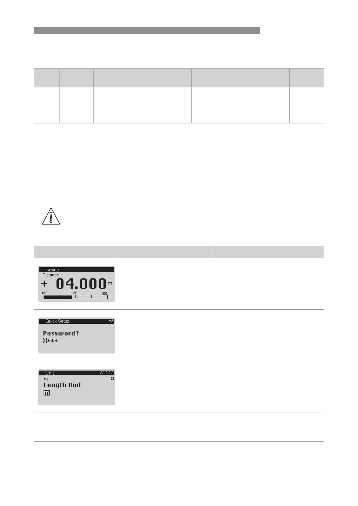
OPTIWAVE 7500 C
4. Master menu
OPERATION
6
Menu
Function Function description Selection list Default
No.
4.0.0 MASTER Factory settings. The settings in this
menu are protected with a password.
Only approved personnel can change
the parameters in this menu. For more
data, speak or write to your local sales
office.
6.4 Further information on device configuration in program mode
6.4.1 Standard Setup
Use this procedure (menu item A4.1 Standard Setup) to change the length unit, tank type, tank
height (this includes the stilliing well diameter and stilling well height if Tank Type
"Stilling Well"), current output variable, 0% range, 100% range, current output range and error
function. Values and parameters that can be changed are shown between the « ... » marks in the
illustrations that follow. Push the keypad buttons in the correct sequence:
CAUTION!
Make sure that you do this procedure before you use the device. The settings in this procedure
have an effect on the performance of the device.
Procedure
Tank Type is set to
Tank TypeTank Type
Screen Steps Description
•
2× [>>>>], 2 × [] and [>>>>].
•
2× [>>>>], 5 × [, [>>>>], 8 × [] and [^^^^]
•
[] and 2 × [>>>>]
•
[] or [] for the selection of the
length unit (m, Cst., in, ft, mm or
cm).
•
[^^^^] to confirm.
•
[] or [] for the selection of the
tank type ().
•
[^^^^] to confirm.
Default screen.
Enter Program Mode and go to menu item
A3 Login.
Enter the password used at this time for the
"Expert" security level. If it is the default
password, refer to
settings (security levels)
Push these buttons to start the Standard
Setup procedure.
Length unit. Make a selection from the list
of parameters.
Tank type. Make a selection from the list of
parameters. .
Protection of the device
on page 47.
www.krohne.com10/2016 - 4004375401 - MA OPTIWAVE 7500 R01 en
79
Page 80
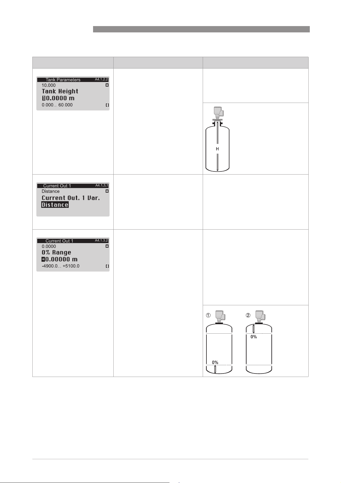
6
OPERATION
Screen Steps Description
•
[>>>>] to change the position of the
cursor.
•
[] to decrease the value (or move
the decimal point one digit to the
left) or [] to increase the value (or
move the decimal point one digit to
the right).
•
[^^^^] to confirm.
•
[] or [] for the selection of the
measurement name (Distance,
Level, Sensor Value or Reflection,
Volume (Mass), Ullage Volume
(Ullage Volume).
•
[^^^^] to confirm.
OPTIWAVE 7500 C
Tank height. The distance from the flange
face / thread stop of the tank connection
down to the tank bottom. If the tank has a
dish-shaped or conical bottom, the tank
height is measured to a point on the tank
bottom directly below the antenna.
Current output 1 variable. The manufacturer
sets the current output variable (for current
output 1) to "Distance” before delivery.
If it is necessary to measure volume, ullage
volume, mass or ullage mass, refer to
How
to configure the device to measure volume
or mass
on page 86.
•
[>>>>] to change the position of the
cursor.
•
[] to decrease the value (or move
the decimal point one digit to the
left) or [] to increase the value (or
move the decimal point one digit to
the right).
•
[^^^^] to confirm.
0% range. Use this step to give the 0%
output setting in the tank.
Refer to the illustrations that follow. When
menu item A4.1.3.1 Current Out. 1 Var.
to "Level", illustration 1 shows the position
of 0% output as a level above the tank
bottom. When menu item A4.1.3.1 Current
Out. 1 Var.
Out. 1 Var. is set to "Distance", illustration
Out. 1 Var.Out. 1 Var.
2 shows the position of 0% output as a
distance below the flange facing or thread
stop of the process connection.
A4.1.3.1 Current Out. 1 Var. is set
A4.1.3.1 Current Out. 1 Var.A4.1.3.1 Current Out. 1 Var.
A4.1.3.1 Current
A4.1.3.1 Current A4.1.3.1 Current
80
www.krohne.com 10/2016 - 4004375401 - MA OPTIWAVE 7500 R01 en
Page 81
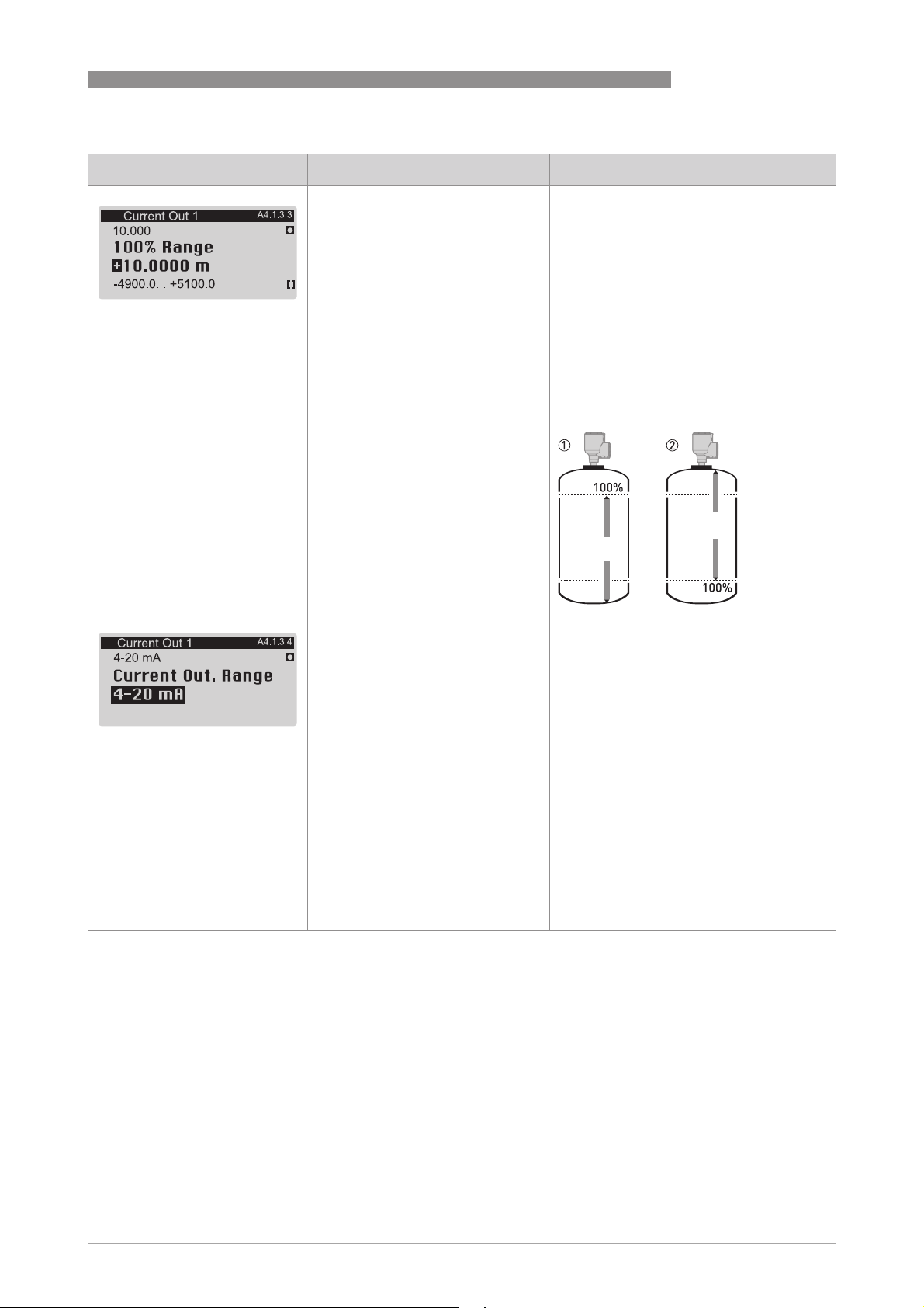
OPTIWAVE 7500 C
Screen Steps Description
•
[>>>>] to change the position of the
cursor.
•
[] to decrease the value (or move
the decimal point one digit to the
left) or [] to increase the value (or
move the decimal point one digit to
the right).
•
[^^^^] to confirm.
OPERATION
100% range. Use this step to give the 0%
output setting in the tank. Refer to the
illustrations that follow. Illustration 1
shows the settings for level. Illustration 2
shows the settings for distance.
Refer to the illustrations that follow. When
menu item A4.1.3.1 Current Out. 1 Var.
to "Level", illustration 1 shows the position
of 100% output as a level above the tank
bottom. When menu item A4.1.3.1 Current
Out. 1 Var.
Out. 1 Var. is set to "Distance", illustration
Out. 1 Var.Out. 1 Var.
2 shows the position of 100% output as a
distance below the flange facing or thread
stop of the process connection.
A4.1.3.1 Current Out. 1 Var. is set
A4.1.3.1 Current Out. 1 Var.A4.1.3.1 Current Out. 1 Var.
A4.1.3.1 Current
A4.1.3.1 Current A4.1.3.1 Current
6
•
[] or [] for the selection of the
current output range (3.8-20.5 mA
(NAMUR), 4-20 mA, 3.8-20.5 mA
(reversed) or 4-20 mA (reversed).
•
[^^^^] to confirm.
Current output range. This menu item gives
current output values to the measuring
range between 0% and 100% values given in
the "0% range" and "100% range" steps.
If you set this menu item to "3.8-20.5 mA":
•
0% Range = 3.8 mA
•
100% Range = 20.5 mA
If you set this menu item to "4-20 mA":
•
0% Range = 4 mA
•
100% Range = 20 mA
If you set this menu item to "3.8-20.5 mA
(reversed)":
•
0% Range = 20.5 mA
•
100% Range = 3.8 mA
If you set this menu item to "4-20 mA
(reversed)":
•
0% Range = 20 mA
•
100% Range = 4 mA
www.krohne.com10/2016 - 4004375401 - MA OPTIWAVE 7500 R01 en
81
Page 82
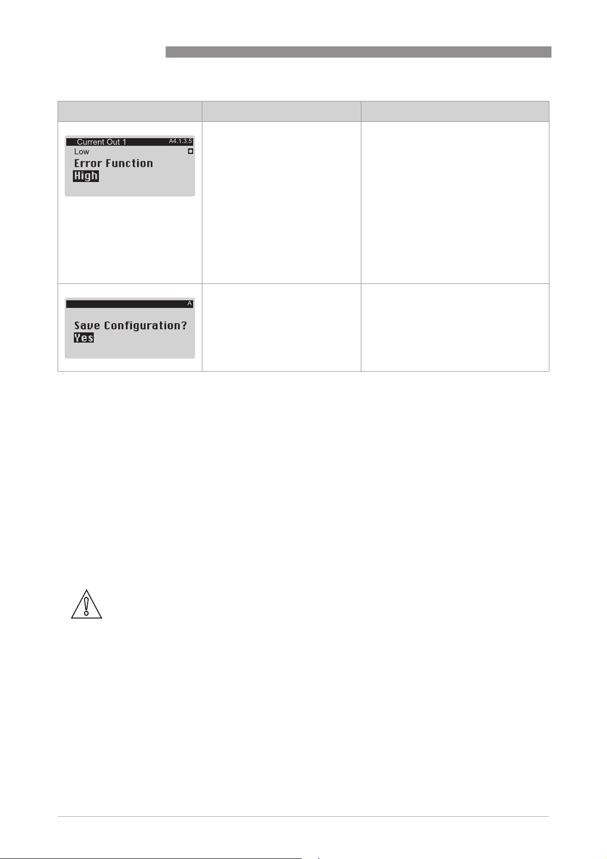
6
OPERATION
Screen Steps Description
•
[] or [] for the selection of the
error function (Off, Hold, High or
Low).
•
[^^^^] to confirm.
•
3× [^^^^] to confirm.
•
[] or [] for the selection of the
save option (Yes, No or Back).
•
[^^^^] to confirm.
OPTIWAVE 7500 C
Error Function. This sets the behaviour of
current output 1 if an error occurs.
If this menu item is set to "Off", no signal is
given (this parameter is not available if
menu item C4.1.4 is set to "3.8-20.5 mA"
(NAMUR) or "3.8-20.5 mA (reversed)"). If
this menu item is set to "Hold", the output
current stays at the value where the error
occurred (this parameter is not available if
menu item C4.1.4 is set to "3.8-20.5 mA"
(NAMUR) or "3.8-20.5 mA (reversed)"). If
this menu item is set to "Low", the output
current changes to 3.5 mA (default value) if
an error occurs. If this menu item is set to
"High", the output current changes to
21.5 mA (default value) if an error occurs.
Save Configuration?
Save Configuration? screen.
Save Configuration?Save Configuration?
Set to "Yes" to save and use the settings and
data and go back to Normal Mode. Set to
"No" to cancel the changes to the device
settings and go back to Normal Mode. Set to
"Back" to stay in Program Mode.
6.4.2 Empty spectrum recording
The empty spectrum recording procedure is important for the performance of the device. We
recommend that the tank is empty or only filled to the minimum level before you do the
procedure.
Use this procedure (menu item A4.2. Empty Spectrum) if there are fixed and moving objects in
the tank that can cause parasitic signals. The device does a scan for objects that do not change
their vertical positions in the tank (heating tubes, agitators, fuel assemblies etc.) and records the
data. The device can then use this data to put the measurement signal through a filter (empty
spectrum).
When the empty spectrum filter is on (when menu item C2.8 Empty Spectrum Enable is set to
"Enable"), it will ignore the parasitic signals. Because the device records the data from the
procedure, it is also not necessary to do the procedure again if you de-energize the device.
CAUTION!
Make sure that the tank is empty or only filled to the minimum level.
Before you do the empty spectrum recording procedure, install the device on the tank. For more
data about how to install the device, refer to
Values and parameters that can be changed are shown between the « ... » marks in the
illustrations that follow. Push the keypad buttons in the correct sequence:
Installation
on page 22.
82
www.krohne.com 10/2016 - 4004375401 - MA OPTIWAVE 7500 R01 en
Page 83
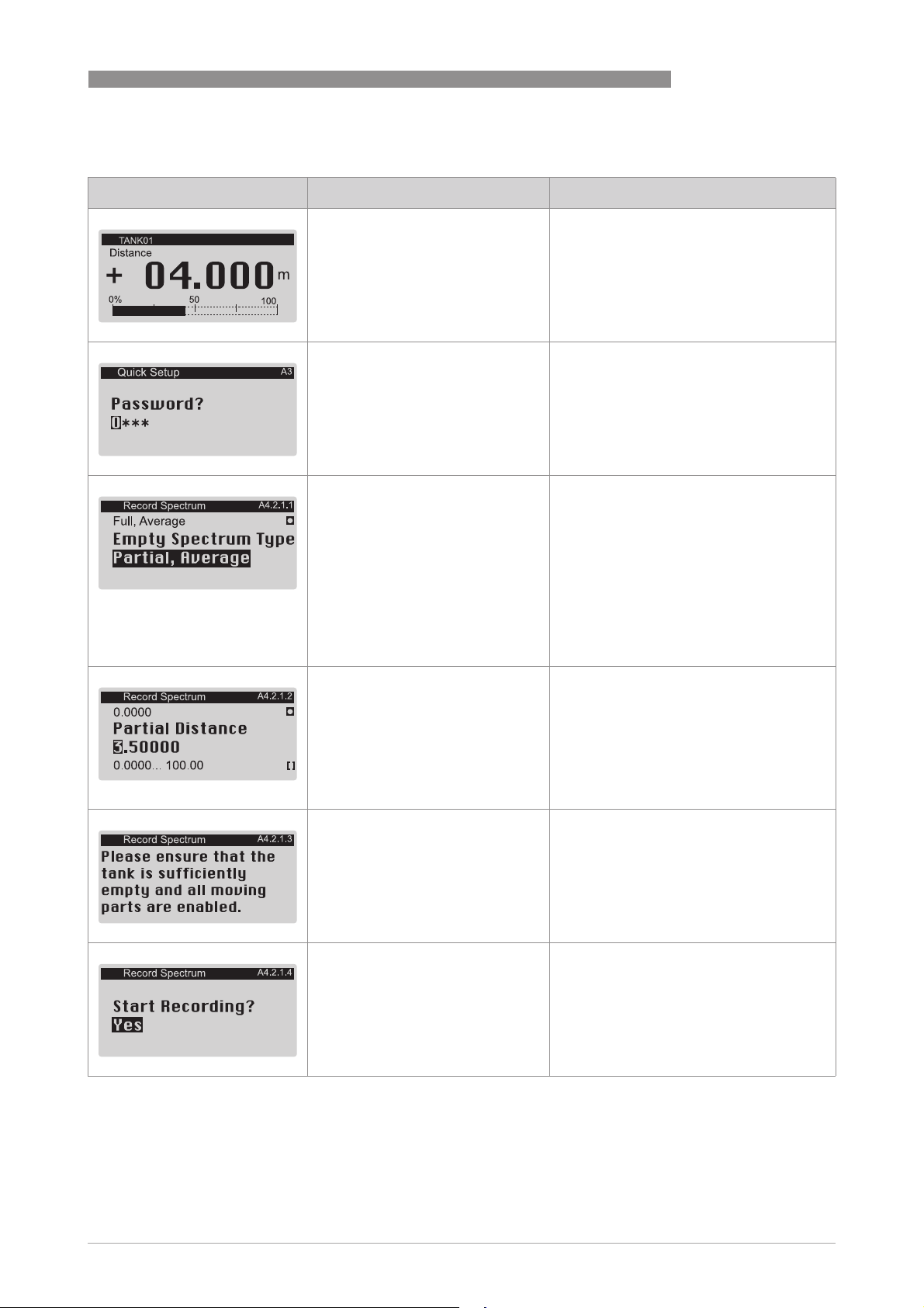
OPTIWAVE 7500 C
Procedure
Screen Steps Description
•
2× [>>>>], 2 × [] and [>>>>].
•
2× [>>>>], 5 × [, [>>>>], 8 × [] and [^^^^]
•
[], [>>>>], [] and 2 × [>>>>].
•
[] or [] for the selection of the
empty spectrum type (Full
(Average), Full (Max), Partial
(Average), Partial (Max)).
•
[^^^^] to confirm.
OPERATION
Default screen.
Enter Program Mode and go to menu item
A3 Login.
Enter the password used at this time for the
"Expert" security level. If it is the default
password, refer to
settings (security levels)
Push these buttons to start the Record
Spectrum (Empty Spectrum) procedure.
Empty spectrum type. Make a selection
from the list of parameters. If you can empty
the tank, set this menu item to "Full,
Average" or "Full, Max". If you cannot empty
the tank, set this menu item to "Partial,
Average" or "Partial, Max".
Protection of the device
on page 47.
6
.
•
[>>>>] to change the position of the
cursor.
•
[] to decrease the value (or move
the decimal point one digit to the
left) or [] to increase the value (or
move the decimal point one digit to
the right).
•
[^^^^] to confirm.
•
[^^^^] to confirm. Make sure that the tank is empty or it
•
[] or [] to change the parameter
("No" or "Yes".
•
[^^^^] to confirm.
Partial distance. If you set Empty Spectrum
Type
Type to "Partial, Average" or "Partial, Max",
TypeType
you will have one more step to do in this
procedure. You must give the distance
(partial distance) of the product surface
from the flange facing or thread stop of the
process connection.
contains not more than the minimum
quantity. .
Start recording? Set this menu item to "Yes"
to continue to the subsequent step. Set this
menu item to "No" to go back to the menu.
Empty Spectrum
Empty Spectrum Empty Spectrum
www.krohne.com10/2016 - 4004375401 - MA OPTIWAVE 7500 R01 en
83
Page 84
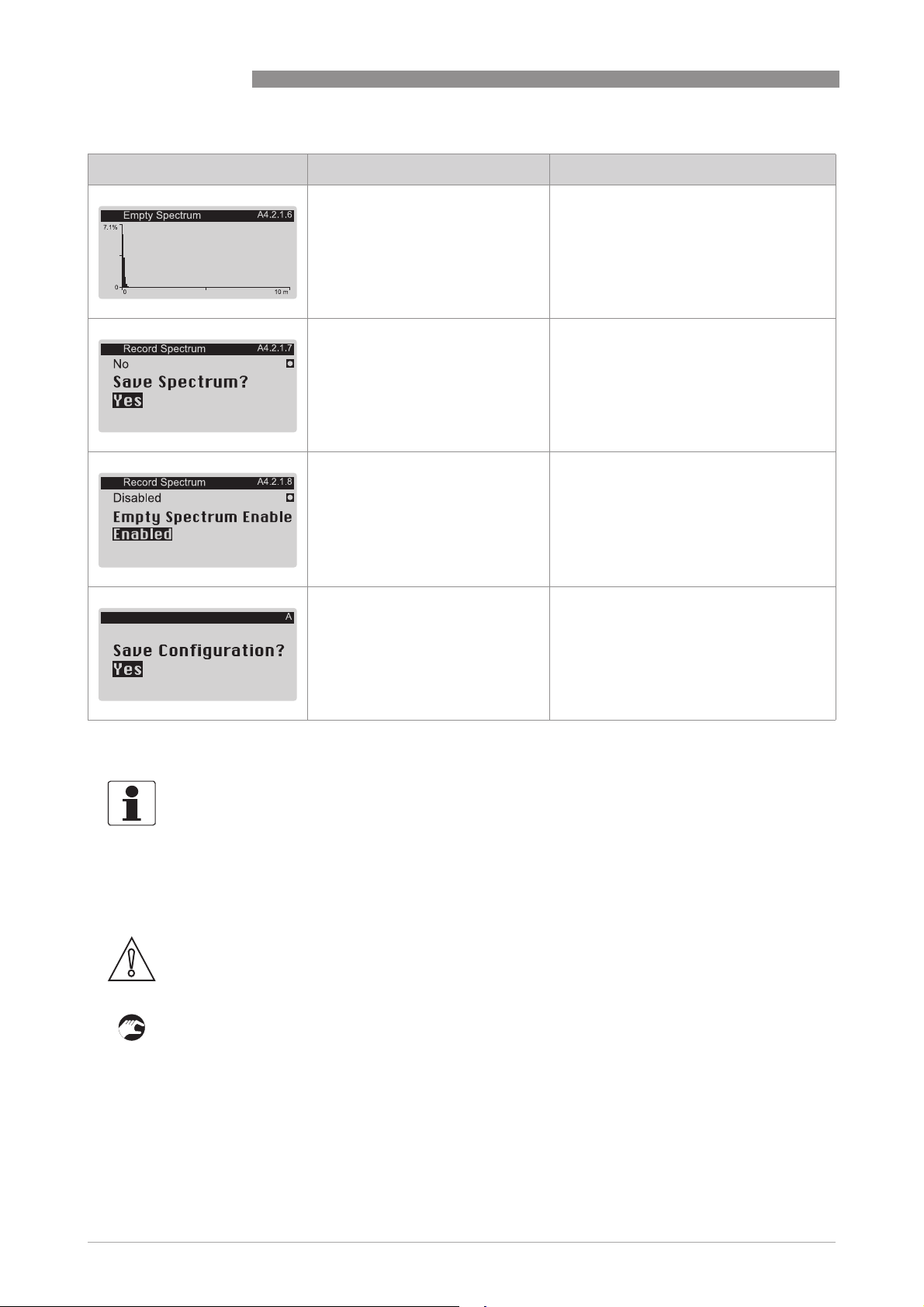
6
OPERATION
Screen Steps Description
•
[^^^^] to confirm.
•
[] or [] to change the parameter
("No" or "Yes".
•
[^^^^] to confirm.
•
[] or [] to change the parameter
("Disable" or "Enable".
•
[^^^^] to confirm.
OPTIWAVE 7500 C
Graph with the results of the empty
spectrum recording.
Save spectrum? If you set the menu item to
"Yes", the device will keep this empty
spectrum recording. If you set the menu
item to "No", the device will reject this data.
Empty Spectrum Enable. If you set the menu
item to "Enable", the device will use the
empty spectrum recording data. If you set
the menu item to "Disable", the device will
not use the empty recording data at this
time.
•
4× [^^^^] to confirm.
•
[] or [] for the selection of the
save option (Yes, No or Back).
•
[^^^^] to confirm.
6.4.3 HART® network configuration
INFORMATION!
For more data, refer to Networks on page 37
The device uses HART® communication to send information to HART®-compatible equipment. It
can operate in either point-to-point or multidrop mode. The device will communicate in
multidrop mode if you change the polling address.
CAUTION!
Make sure that the address for this device is different from others in the multidrop network.
How to change from point-to-point to multidrop mode
• Enter Program mode.
• Push 2 × [], [>>>>], 4 × [], 2 × [>>>>], [] and 2 × [>>>>] to go to menu item C5.1.2.1 Polling Adress.
• Enter a value between 001 and 063 and push [^^^^] to confirm.
• Push [^^^^] again and again to go back to the Save Configuration
• Push [] or [] to set the screen to "Yes" and push [^^^^].
Save Configuration?
Save Configuration? screen.
Save Configuration?Save Configuration?
Set to "Yes" to save and use the settings and
data and go back to Normal Mode. Set to
"No" to cancel the changes to the device
settings and go back to Normal Mode. Set to
"Back" to stay in Program Mode.
.
Save Configuration screen.
Save ConfigurationSave Configuration
84
www.krohne.com 10/2016 - 4004375401 - MA OPTIWAVE 7500 R01 en
Page 85
OPTIWAVE 7500 C
i The output is set to multidrop mode. The current output is set to 4 mA. This value does not
change in multidrop mode.
How to change from multidrop to point-to-point mode
• Enter Program mode.
• Push 2 × [], [>>>>], 4 × [], 2 × [>>>>], [] and 2 × [>>>>] to go to menu item C5.1.2.1 Polling Address.
• Enter the value 000 and push [^^^^] to confirm.
• Push [^^^^] again and again to go back to the Save Configuration
• Push [] or [] to set the screen to "Yes" and push [^^^^].
i The output is set to point-to-point mode. The current output changes to a range of 4...20 mA
or 3.8...20.5 mA (this range is set in menu item C4.1.4 Current Out. Range).
6.4.4 Distance measurement
Menu items related to distance measurement are:
• Current output 1 menu (C4.1)
• Tank Height (C1.2 – if C1.1 Tank Type is set to 'Storage", "Process" or Agitator") or Stilling
Well Height (C1.3 – if C1.1 Tank Type is set to "Stilling Well")
• Blocking Distance (C1.5)
Save Configuration screen.
Save ConfigurationSave Configuration
OPERATION
6
INFORMATION!
Reference Offset
Reference Offset
Reference OffsetReference Offset
If you move the reference point above the flange, add this value when you give a distance for the
0% Range and 100% Range settings. If you move the reference point below the flange, subtract
this value when you give a distance for the 0% Range and 100% Range settings.
CAUTION!
If the distance for 0% Range (standard scale) is set in the blocking distance, it is possible that the
device will not be able to use the full current output range.
6.4.5 Level measurement
Menu items related to level measurement are:
• Current output 1 menu (C4.1)
• Tank Height (C1.2 – if C1.1 Tank Type is set to 'Storage", "Process" or Agitator") or Stilling
Well Height (C1.3 – if C1.1 Tank Type is set to "Stilling Well")
• Blocking Distance (C1.5)
INFORMATION!
Tank Bottom Offset
Tank Bottom Offset
Tank Bottom OffsetTank Bottom Offset
If you move the tank bottom offset below the tank bottom (or the bottom of the stilling well), add
this value when you give a level for the 0% Range and 100% Range settings. If you move the tank
bottom offset above the tank bottom (or the bottom of the stilling well), subtract this value when
you give a level for the 0% Range and 100% Range settings.
CAUTION!
If the distance for 100% Range (standard scale) is set in the blocking distance, it is possible that
the device will not be able to use the full current output range.
www.krohne.com10/2016 - 4004375401 - MA OPTIWAVE 7500 R01 en
85
Page 86

6
OPERATION
6.4.6 How to configure the device to measure volume or mass
The device can be configured to measure volume or mass. It can also be configured to a custom
quantity to be measured. You can set up a strapping table in the conversion menu (C3
Conversion). Each entry is a pair of data (level – volume, level – mass or level – custom
measurement). The strapping table must have a minimum of 2 entries and a maximum of 50. The
reference point for the table is the bottom of the tank (as given in menu item Tank Height (C1.2)
or Stilling Well Height (C1.3)
CAUTION!
Enter the data in numerical sequence (strapping table entry number 01, 02 etc.).
How to prepare a strapping table (conversion table)
• Enter Program Mode.
• Push 2 × [], [>>>>], 6 × [], [>>>>], 3 × [] and 3 × [>>>>] to go to C7.5.1 Length Unit.
• Push [] and [] to find the length unit that you will use in the table.
• If it is necessary to make a volume table, push [^^^^] to go back to the sub-menu level and then
push 2 × [] and [>>>>] to go to C7.5.3 Volume.
• Push [] and [] to find the volume unit that you will use in the table.
• Push 3 × [^^^^] to go to the sub-menu level and then 4 × [], 2 × [>>>>] to delete strapping table data
that the device uses at this time (Erase Table?). Push [] and [] to set this menu item to
"Yes" to delete the data.
• Push [^^^^
mass linearization).
• Push [^^^^] to go to the sub-menu level and then [] and [>>>>] to enter the first point on the table.
• Push [^^^^] to make the strapping table.
• Enter the length value and push [^^^^].
• Enter the conversion value and push [^^^^] to go to the sub-menu level.
• Push [>>>>] to enter the subsequent point (02, 03, ..., 50) on the table.
• Repeat the last 3 steps to complete the table.
• If the table is complete, push [^^^^] again and again to go back to the "Save Configuration?"
screen.
• The device will ask you to save or cancel your settings. Push [] or [] to make a selection
from Yes
to "Yes" or No", push [^^^^] to accept (Yes) or reject (No) the new settings.
i If you push [^
] and then [] and [] to make a selection from the conversion table options (volume,
Yes, No
No or Back
Back. Back
YesYes
NoNo
^] when the screen is set to "Yes", the device will store the data for the
^^
strapping table and go back to normal mode.
Back makes the display go back to Program mode. If this screen is set
BackBack
BackBack
OPTIWAVE 7500 C
86
The device will give more accurate volume readings if you give more conversion data in these
areas:
• Surfaces with curves.
• Sudden changes in the cross section.
Refer also to the illustration that follows:
www.krohne.com 10/2016 - 4004375401 - MA OPTIWAVE 7500 R01 en
Page 87
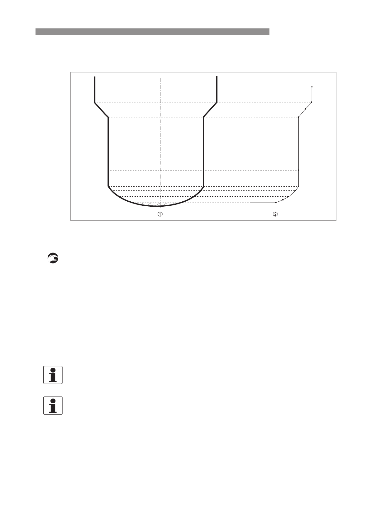
OPTIWAVE 7500 C
OPERATION
6
Figure 6-7: A plot of points for a volume or mass table
1
2
How to delete a volume or mass table
• Enter Program Mode.
• Push 2 × [], [>>>>], 2 × [] and 2 × [>>>>] to go to C3.1.1 Erase Table?.
• To delete strapping table data that the device uses at this time (Erase Table?), push [] and
[] to set this menu item to "Yes".
• Push [^^^^] again and again to go back to the "Save Configuration?" screen.
• The device will ask you to save or cancel your settings. Push [] or [] to make a selection
from Yes
Yes, No
No or Back
Back. Back
YesYes
NoNo
to "Yes" or No", push [^^^^] to accept (Yes) or reject (No) the new settings.
i If you push [^
strapping table and go back to normal mode.
^] when the screen is set to "Yes", the device will delete the data for the
^^
Back makes the display go back to Program mode. If this screen is set
BackBack
BackBack
6.4.7 How to make a filter to remove radar signal interference
INFORMATION!
.
INFORMATION!
6.4.8
You can offset the tank bottom reference point to find the delayed radar reflection. Obey the
instructions that follow:
www.krohne.com10/2016 - 4004375401 - MA OPTIWAVE 7500 R01 en
87
Page 88
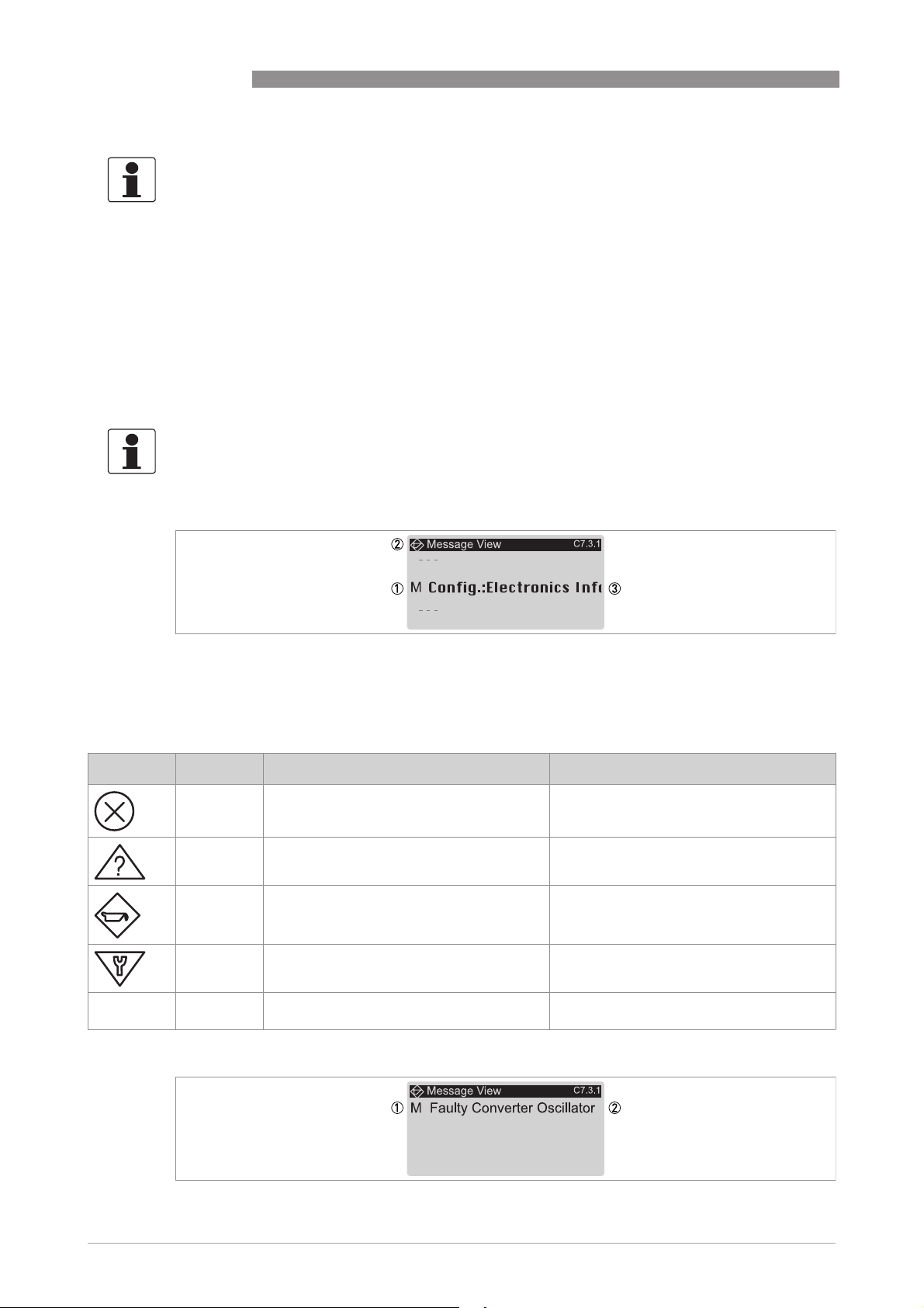
6
OPERATION
INFORMATION!
6.5 Status messages and diagnostic data
Messages shown agree with NAMUR Guidelines NE 107. The error messages for the device are
divided into status groups, each with one status signal. There are 16 status groups with fixed
status signals and 8 groups with status signals that can be changed. The status groups are also
divided into 4 groups: Sensor, Electronics, Configuration and Process.
Each status message (or status signal) has a special symbol which agrees with the NAMUR
Guidelines. This symbol is shown with the message.
INFORMATION!
The status group name and the status signal (F/S/M/C) are shown. For more data, refer to the
table that follows.
OPTIWAVE 7500 C
Figure 6-8: Device status and error messages
1 Device status letter code (NAMUR NE 107). In this example, M = Maintenance required.
2 Device status symbol (NAMUR NE 107)
3 Error message
Status messages (NAMUR NE 107)
Symbol Letter Message Description and effect
FFFF Failure No measurement is possible.
S Out of specification Measurements are available but they are
M Maintenance required Measurements continue to be accurate but
C Function check A test function is on. The value shown does
I Information This status message does not have an effect
not sufficiently accurate. Do a check.
this could change after a short time.
not agree with the correct measured value.
on device measurements.
88
www.krohne.com 10/2016 - 4004375401 - MA OPTIWAVE 7500 R01 en
Page 89
OPTIWAVE 7500 C
Figure 6-9: Description of the error (C7.3.1 Message View)
1 Device status letter code (NAMUR NE 107). In this example, M = Maintenance required.
2 Description of error
OPERATION
6
Status
Status group Error message Description Corrective action
type
FFFF Sensor
FFFF Electronics
Sensor
SensorSensor
Corrupt Sensor Parameter The device settings do not
No Signal There is no signal from the
Microwave Tuning Voltage
Error
Sensor Comm. Error Internal bus communication
No measurement value The converter receives no
Electronics
ElectronicsElectronics
Fatal Converter Error (DM)
1
Fatal Converter Error (CO)
2
Fatal Converter Error
(Generic)
CO Safety Reaction
Internal Comm. Error Internal bus communication
Power Supply Error Internal voltage is too low to
Sensor/Conv. FW Mismatch The sensor firmware version
Max. Number of Restarts The device could not start
Inconsistent Parameters Internal bus communication
Sensor Comm. Error Internal bus communication
3
agree with the correct
process conditions
antenna or the antenna
signal is too weak for a long
time.
A microwave error occurred. De-energize and then
error or hardware failure.
measurement data for a
long time.
An electronics or hardware
failure occurred.
An electronics or hardware
failure occurred.
An electronics or hardware
failure occurred.
Current Output Safety
Reaction. This error
message is shown if the
current output is less than
3.6 mA or more than 21 mA.
error.
energize the sensor.
in the sensor does not agree
with the converter firmware
version.
the measuring mode after a
given number of times that
the device was de-energized
and then energized again.
error.
error or hardware failure.
Do a check of the device
settings (tank height etc.).
Do a check the device
installation. For more data
about installation, refer to
the handbook. If the
message is shown again,
speak or write to the
manufacturer.
energize the device again.
If the message is shown
again, speak or write to the
manufacturer.
De-energize and then
energize the device again.
If the message is shown
again, speak or write to the
manufacturer.
Check the electrical
connections to the power
supply connection or replace
the converter.
De-energize and then
energize the device again.
If the message is shown
again, speak or write to the
manufacturer.
www.krohne.com10/2016 - 4004375401 - MA OPTIWAVE 7500 R01 en
89
Page 90
6
OPERATION
OPTIWAVE 7500 C
Status
Status group Error message Description Corrective action
type
FFFF Configuration
Configuration
ConfigurationConfiguration
Inconsistent NVRAM Incorrect data in the
Incons. Converter Calib. Incorrect calibration data in
Incons. Sensor Calibration Incorrect calibration data in
NVRAMs Mismatch The serial number of the
Conv. NVRAM Layout Error Incorrect data in the
Disp. NVRAM Layout Error Incorrect data after an
CO Float Error
2
parameter memory
the converter module
the sensor module
display screen does not
agree with the serial
number of the electronics
module.
parameter memory
update of the firmware.
The device cannot use the
measurement data because
the device settings are
incorrect.
De-energize and then
energize the device again.
If the message is shown
again, speak or write to the
manufacturer.
Speak or write to the
manufacturer.
Make sure that the display
screen agrees with the
electronic module. Go to
Full Setup
Full Setup > Device
Full SetupFull Setup
Information
Information and record the
InformationInformation
data in menu items C7.1.5
Electronic Revision
Electronic Revision and
Electronic RevisionElectronic Revision
C7.1.6 Software Revision
C7.1.6 Software Revision. If
C7.1.6 Software RevisionC7.1.6 Software Revision
it is necessary, speak or
write to the manufacturer.
De-energize and then
energize the device again.
If the message is shown
again, speak or write to the
manufacturer.
You must make the device
go back to its factory
settings. Enter Program
Mode. Set the device to the
"Expert" security level. Go to
Full Setup
Full Setup > Device
Full SetupFull Setup
Factory Default
Factory Default > Reset to
Factory DefaultFactory Default
Factory Default?
Factory Default? and set this
Factory Default?Factory Default?
menu item to "Yes". Then go
back to Normal Mode and
set the "Save
Configuration?" page to
"Yes". De-energize and then
energize the device again.
Device >
DeviceDevice
Device >
DeviceDevice
Reset to
Reset to Reset to
C7.1.5
C7.1.5 C7.1.5
CCCC Electronics
90
Electronics
ElectronicsElectronics
FW Update A firmware update of the
If the message is shown
again, speak or write to the
manufacturer.
converter module continues.
www.krohne.com 10/2016 - 4004375401 - MA OPTIWAVE 7500 R01 en
Wait for the firmware update
to finish.
Page 91
OPTIWAVE 7500 C
OPERATION
6
Status
Status group Error message Description Corrective action
type
CCCC Configuration
SSSS Sensor
Configuration
ConfigurationConfiguration
Sensor Sim. Active The device simulates a
Current Out. Sim. Active The device simulates a
HART Sim. Active You can use a HART®
LCO Simulation Active The device simulate a a
SysMon Simulation Active A system monitor sets the
Sensor
SensorSensor
Sensor Voltage Low The voltage supplied to the
Strong Signal The signal amplitude is too
measurement value that is
set in menu item B1.1 Set
Value
Value. This measurement
ValueValue
value can be a level,
distance or reflection value.
If you made a strapping
table, the device can also
simulate a volume or mass
value.
current output value that is
set in menu item B1.2
Output
Output. The current output
OutputOutput
test range is 3.6...21.5 mA.
interface to simulate a
measurement value in the
device.
current output value set in
sub-menu B1 Simulation
(distance, level, ullage
volume, ullage mass,
linearized distance, volume,
mass or linearized level).
device to a simulated
current output value.
sensor is too low.
large. It is possible that the
signal is saturated.
B1.1 Set
B1.1 Set B1.1 Set
B1.2
B1.2 B1.2
Push "Enter" to stop the
test.
Push "Enter" to stop the
test.
Use the HART® interface to
stop the test.
Push "Enter" to stop the
test.
Push "Enter" to stop the
test.
Do a check of the power
supply.
Make sure that the device
installation agrees with the
data in the handbook.
Peak Lost (Level Lost) No signal peak was found in
Overfill The signal peak is in the
Elec. Temp. Out Of Spec. The temperature of the
SSSS Electronics
Electronics
ElectronicsElectronics
Elec. Temp. Out Of Spec. The temperature of the
the Search Window for a
long time (>20 s).
blocking distance (refer to
menu item C1.5 Blocking
Distance). .
sensor is not in the specified
limits.
converter is not in the
specified limits.
www.krohne.com10/2016 - 4004375401 - MA OPTIWAVE 7500 R01 en
If the message is shown
again, speak or write to the
manufacturer.
Make sure that the device
installation agrees with the
data in the handbook. . If it is
necessary, change the
device settings and do a new
empty spectrum recording.
If the message is shown
again, speak or write to the
manufacturer.
Make sure that the device
settings are correct and the
process conditions are in the
specified limits.
Make sure that the device is
operated in the permitted
ambient temperature range.
Make sure that the device is
operated in the permitted
ambient temperature range.
91
Page 92

6
OPERATION
OPTIWAVE 7500 C
Status
Status group Error message Description Corrective action
type
SSSS Process
MMMM Sensor
Process
ProcessProcess
CO Undersaturation
CO Oversaturation
Sensor
SensorSensor
Weak Signal The signal amplitude is too
Bad Measurement Quality
(Old Measurement)
2
2
The measurement value is
less than the minimum
value of the current output
range. The current output
cannot go lower than its
minimum value and thus
does not agree with the
correct measurement value.
The measurement value is
more than the maximum
value of the current output
range. The current output
cannot go higher than its
maximum value and thus
does not agree with the
correct measurement value.
small.
The measurement value is
incorrect and does not
change for more than 10 s.
Do a check of the process
conditions and the minimum
current output value.
Do a check of the process
conditions and the
maximum current output
value.
Make sure that the device
installation agrees with the
data in the handbook.
If the message is shown
again, it is possible that a
different antenna must be
installed. Speak or write to
the manufacturer.
Make sure that the device
installation agrees with the
data in the handbook.
Empty Spectrum invalid The empty spectrum
recording does not agree
with the process conditions
at this time (e.g. tank
height).
Speak or write to the
manufacturer.
Do a new empty spectrum
recording.
92
www.krohne.com 10/2016 - 4004375401 - MA OPTIWAVE 7500 R01 en
Page 93

OPTIWAVE 7500 C
OPERATION
6
Status
Status group Error message Description Corrective action
type
MMMM Sensor Information
1 DM = data manager
2 CO = current output
3 This error message is shown if the device is in SIL mode. CO = current output.
Sensor Information
Sensor InformationSensor Information
Failed Sensor MCU Test The sensor electronics does
Failed Sensor Input Test
Bad Spectrum Quality There is a large change in
Peak Lost in Tank Bottom The signal was lost near the
RC-Oscillator out of bounds The sensor electronics does
Sensor Reference out of
range
XCO out of bounds
Microwave Lock Error
Microwave Sweep Duration
Error
Microwave Supply Voltage
Error
a continuous self test
procedure. The test finds a
fault.
signal strength.
tank bottom. Spherical or
conical tanks can cause the
device to show this status
message.
a continuous self test
procedure. The test finds a
fault.
De-energize and then
energize the device again.
If the message is shown
again, speak or write to the
manufacturer.
Make sure that the device
installation agrees with the
data in the handbook.
If the message is shown
again, we recommend that
you install the device in a
stilling well.
The device will measure the
level of tak contents if you
fill the tank.
If the message is shown,
speak or write to the
manufacturer.
De-energize and then
energize the device again.
If the message is shown
again, speak or write to the
manufacturer.
www.krohne.com10/2016 - 4004375401 - MA OPTIWAVE 7500 R01 en
93
Page 94
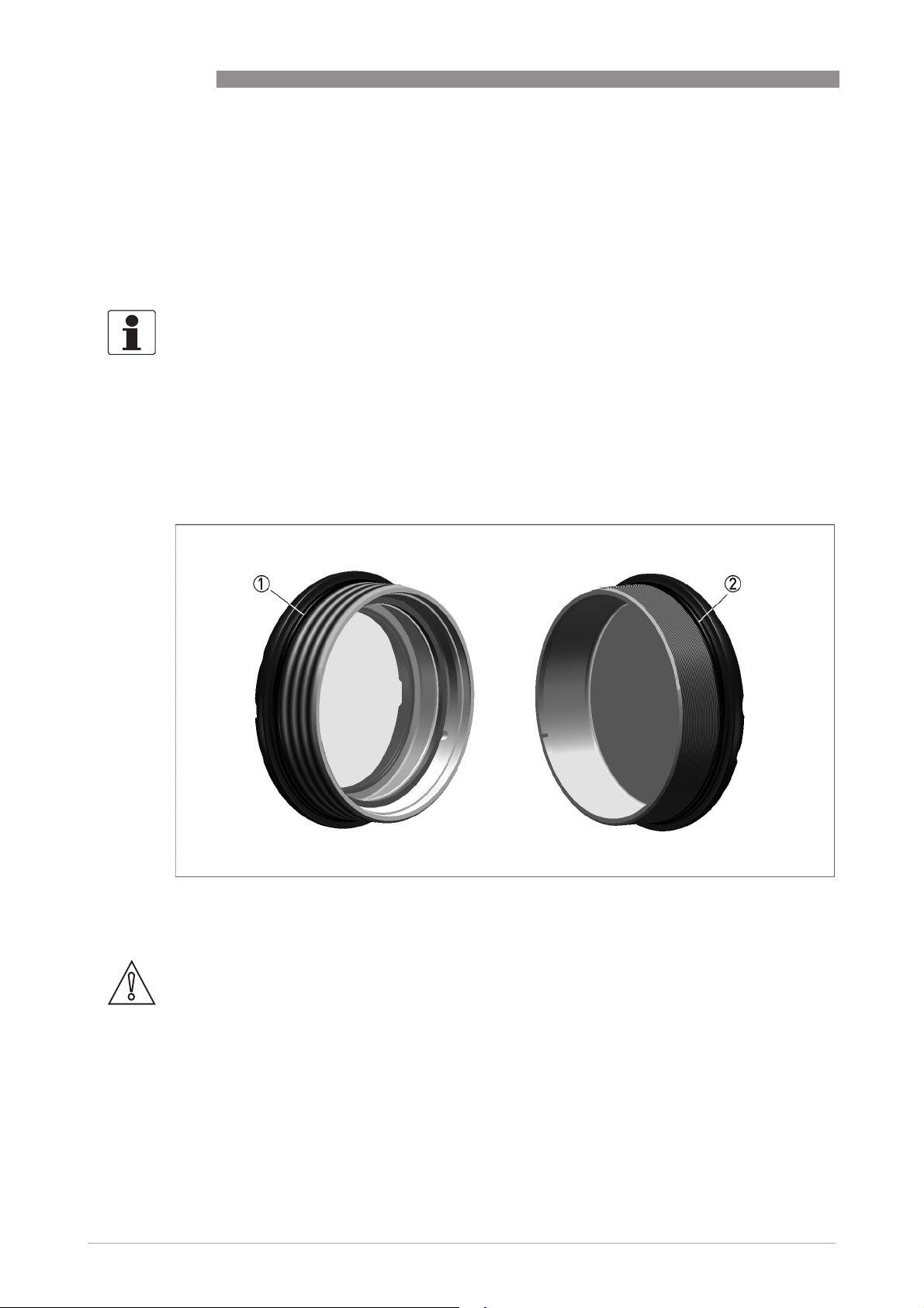
7
SERVICE
7.1 Periodic maintenance
7.1.1 General notes
In normal operational conditions, no maintenance is necessary. If it is necessary, maintenance
must be done by approved personnel (the manufacturer or personnel approved by the
manufacturer).
INFORMATION!
For more data about regular inspections and maintenance procedures for devices with Ex and
other approvals, refer to the related supplementary instructions.
7.1.2 Maintainance of the O-rings for the housing covers
If the display cover 1 or the terminal compartment cover 2 of the housing is opened and closed,
make sure that the O-rings are correctly greased or, if it is necessary, replaced. For more data
about the replacement of the O-rings, refer to
Spare parts
OPTIWAVE 7500 C
on page 116.
94
Figure 7-1: Maintainance of the O-rings
1 Display cover
2 Terminal compartment cover
CAUTION!
Use multi-purpose grease that is appicable for the operating temperature range the O-ring with
the properties that follow:
•
Operating temperature range of -30...+130°C / -22...+266°F without a negative effect on the
lubrification of the O-ring
•
Without silicone
•
The bonding properties must be satisfactory
•
Lithium-saponified
•
Water-resistant
•
Agrees with the O-ring material
www.krohne.com 10/2016 - 4004375401 - MA OPTIWAVE 7500 R01 en
Page 95
OPTIWAVE 7500 C
7.1.3 How to clean the top surface of the device
WARNING!
Do not let more than 5 mm / 0.2
possible source of ignition in a potentially explosive atmosphere.
¨
of dust collect on the top surface of the device. This is a
Obey these instructions:
• Keep the thread of the terminal compartment cover clean.
• If dirt collects on the device, clean it. Wipe the plastic sun cover with a damp cloth.
7.1.4 How to clean horn antennas under process conditions
If it is possible that there will be build-up, a purging option is available for horn antennas.
CAUTION!
Purge the antenna at intervals to make sure that the inner surface of the antenna stays clean
and the device measures accurately.
For more data, refer to the table that follows:
SERVICE
7
7.2 Service warranty
WARNING!
Only approved personnel can do an inspection of the device and repairs. If you find a problem,
send the device back to the supplier for inspection and/or repairs.
Servicing by the customer is limited by warranty to:
• The removal and installation of the device.
• Compact version:
Compact version: The removal and installation of the signal converter (with the weather
Compact version:Compact version:
protection, if this option is attached). For more data, refer to
converter
For more data on how to prepare the device before you send it back,, refer to
device to the manufacturer
on page 28.
7.3 Spare parts availability
The manufacturer adheres to the basic principle that functionally adequate spare parts for each
device or each important accessory part will be kept available for a period of 3 years after
delivery of the last production run for the device.
This regulation only applies to spare parts which are subject to wear and tear under normal
operating conditions.
How to turn or remove the signal
Returning the
on page 96.
7.4 Availability of services
The manufacturer offers a range of services to support the customer after expiration of the
warranty. These include repair, maintenance, technical support and training.
www.krohne.com10/2016 - 4004375401 - MA OPTIWAVE 7500 R01 en
95
Page 96
7
SERVICE
INFORMATION!
For more precise information, please contact your local sales office.
7.5 Returning the device to the manufacturer
7.5.1 General information
This device has been carefully manufactured and tested. If installed and operated in accordance
with these operating instructions, it will rarely present any problems.
CAUTION!
Should you nevertheless need to return a device for inspection or repair, please pay strict
attention to the following points:
•
Due to statutory regulations on environmental protection and safeguarding the health and
safety of the personnel, the manufacturer may only handle, test and repair returned devices
that have been in contact with products without risk to personnel and environment.
•
This means that the manufacturer can only service this device if it is accompanied by the
following certificate (see next section) confirming that the device is safe to handle.
OPTIWAVE 7500 C
CAUTION!
If the device has been operated with toxic, caustic, radioactive, flammable or water-endangering
products, you are kindly requested:
•
to check and ensure, if necessary by rinsing or neutralising, that all cavities are free from
such dangerous substances,
•
to enclose a certificate with the device confirming that is safe to handle and stating the
product used.
96
www.krohne.com 10/2016 - 4004375401 - MA OPTIWAVE 7500 R01 en
Page 97
OPTIWAVE 7500 C
7.5.2 Form (for copying) to accompany a returned device
CAUTION!
To avoid any risk for our service personnel, this form has to be accessible from outside of the
packaging with the returned device.
Company: Address:
Department: Name:
Tel. no.: Fax no. and/or Email address:
Manufacturer's order no. or serial no.:
The device has been operated with the following medium:
This medium is: radioactive
water-hazardous
toxic
caustic
flammable
We checked that all cavities in the device are free from such substances.
We have flushed out and neutralized all cavities in the device.
SERVICE
7
We hereby confirm that there is no risk to persons or the environment through any residual media contained in the
device when it is returned.
Date: Signature:
Stamp:
7.6 Disposal
CAUTION!
Disposal must be carried out in accordance with legislation applicable in your country.
Separate collection of WEEE (Waste Electrical and Electronic Equipment) in the European Union:
Separate collection of WEEE (Waste Electrical and Electronic Equipment) in the European Union:
Separate collection of WEEE (Waste Electrical and Electronic Equipment) in the European Union:Separate collection of WEEE (Waste Electrical and Electronic Equipment) in the European Union:
According to the directive 2012/19/EU, the monitoring and control instruments marked with the
WEEE symbol and reaching their end-of-life must not be disposed of with other waste
The user must dispose of the WEEE to a designated collection point for the recycling of WEEE or
send them back to our local organisation or authorised representative.
must not be disposed of with other waste.
must not be disposed of with other wastemust not be disposed of with other waste
www.krohne.com10/2016 - 4004375401 - MA OPTIWAVE 7500 R01 en
97
Page 98
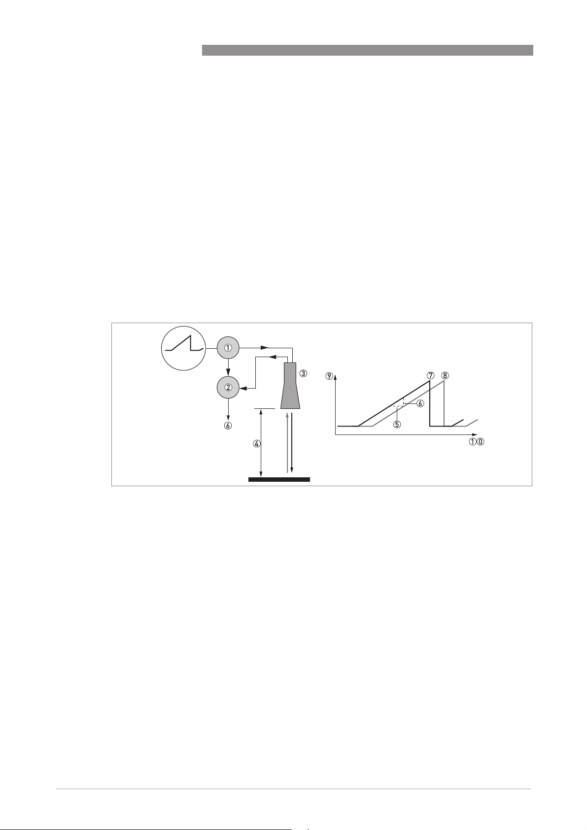
8
TECHNICAL DATA
8.1 Measuring principle
A radar signal is emitted via an antenna, reflected from the product surface and received after a
time t. The radar principle used is FMCW (Frequency Modulated Continuous Wave).
The FMCW-radar transmits a high frequency signal whose frequency increases linearly during
the measurement phase (called the frequency sweep). The signal is emitted, reflected on the
measuring surface and received with a time delay, t. Delay time, t=2d/c, where d is the distance
to the product surface and c is the speed of light in the gas above the product.
For further signal processing the difference Δf is calculated from the actual transmitted
frequency and the received frequency. The difference is directly proportional to the distance. A
large frequency difference corresponds to a large distance and vice versa. The frequency
difference Δf is transformed via a Fourier transformation (FFT) into a frequency spectrum and
then the distance is calculated from the spectrum. The level results from the difference between
the tank height and the measured distance.
OPTIWAVE 7500 C
Figure 8-1: Measuring principle of FMCW radar
1 Transmitter
2 Mixer
3 Antenna
4 Distance to product surface, where change in frequency is proportional to distance
5 Differential time delay, Δt
6 Differential frequency, Δf
7 Frequency transmitted
8 Frequency received
9 Frequency
10 Time
98
www.krohne.com 10/2016 - 4004375401 - MA OPTIWAVE 7500 R01 en
Page 99
OPTIWAVE 7500 C
TECHNICAL DATA
8.2 Technical data
INFORMATION!
•
The following data is provided for general applications. If you require data that is more
relevant to your specific application, please contact us or your local sales office.
•
Additional information (certificates, special tools, software,...) and complete product
documentation can be downloaded free of charge from the website (Downloadcenter).
Measuring system
Measuring principle 2-wire loop-powered level transmitter; FMCW radar
Frequency range W-band (78...82 GHz)
Max. transmitted power 0.3 mW EIRP (TLPR: outside of the tank; LPR: in half sphere)
Application range Level measurement of liquids, pastes and slurries
Primary measured value Distance and reflection
Secondary measured value Level, volume and mass
Design
Construction The measurement system consists of a measuring sensor (antenna) and a signal
Options Integrated LCD display (-20..+70°C/ -4…+158°F); if the ambient temperature is not
Max. measuring range 37.5 m / 123 ft (option: 100 m / 328 ft)
Min. tank height 0.3 m / 12¨
Top dead zone 75 mm / 3¨, when tank height ≤ 37.5 m / 123 ft
Beam angle Convex lens, Ø25 mm: 11°
Display and user interface
Display and user interface
Display and user interfaceDisplay and user interface
Display LCD display
Interface languages English, French, German, Italian, Spanish, Portuguese, Chinese (simplified),
converter
in these limits, then this condition can stop the display
Weather protection
Also depends on the dielectric constant of the product and the installation type.
Refer also to "Antenna selection".
200 mm / 7.9¨, when tank height > 37.5 m / 123 ft
Convex lens, Ø40 mm: 7.8°
128 × 64 pixels in 8-step greyscale with 4-button keypad
Japanese, Czech, Polish and Turkish
8
Measuring accuracy
Resolution 1mm/ 0.04¨
Repeatability ±1mm/ ±0.04¨
Accuracy Standard: ±2mm/ ±0.8¨, when distance <10m/ 33ft;
Digital temperature drift Max. ±10 mm / ±0.39¨ for the full temperature range
Reference conditions acc. to EN 61298-1
Reference conditions acc. to EN 61298-1
Reference conditions acc. to EN 61298-1Reference conditions acc. to EN 61298-1
Temperature +15...+25°C / +59...+77°F
Pressure 1013 mbara ±50 mbar / 14.69 psia ±0.73 psi
Relative air humidity 60% ±15%
±0.02% of measured distance, when distance > 10 m / 33 ft
www.krohne.com10/2016 - 4004375401 - MA OPTIWAVE 7500 R01 en
99
Page 100
8
TECHNICAL DATA
Target Metal plate in an anechoic chamber
Operating conditions
Temperature
Temperature
TemperatureTemperature
Ambient temperature -40…+80°C/ -40…+176°F
Relative humidity 0...99%
Storage temperature -50…+85°C/ -58…+185°F
Process connection temperature
(higher temperature on request)
Pressure
Pressure
PressurePressure
Process pressure -1…40 barg / -14.5…580 psig;
Other conditions
Other conditions
Other conditionsOther conditions
Dielectric constant (εr) Direct mode: ≥1.5
Ingress protection IEC 60529: IP66/67
Maximum rate of change 10 m/min / 32.8 ft/min
Ex: see supplementary operating instructions or approval certificates
-20…+150°C/ -4…+302°F (the process connection temperature must agree with
the temperature limits of the gasket material. Refer to "Materials" in this table.)
Ex: see supplementary operating instructions or approval certificates
subject to the process connection used and the flange temperature
TBF mode: ≥1.1
Refer also to "Technical data: Antenna selection".
NEMA 250: NEMA type 4X (housing) and type 6P (antenna)
OPTIWAVE 7500 C
Installation conditions
Process connection size The nominal diameter (DN) should be equal to or larger than the antenna diameter.
Process connection position Make sure that there are not any obstructions directly below the process
Dimensions and weights For dimensions and weights data, refer to on page .
connection for the device. For more data, refer to
Installation
on page 22.
Materials
Housing Standard: Polyester-coated aluminium
Option: Stainless steel (1.4404 / 316L)
Wetted parts, including antenna PEEK – this material agrees with FDA regulations
Process connection PEEK
Gaskets (and o-rings for the
sealed antenna extension option)
Feedthrough PEI (-50...+150°C / -58...+302°F – max. range. The feedthrough temperature limits
Cable gland Standard: none
Weather protection (Option) Stainless steel (1.4404 / 316L)
BioControl®: FKM/FPM (-20…+150°C/ -4…+302°F); EPDM (-20°C…+150°C/ -
4…+302°F)
SMS, Tri-Clamp®, VARIVENT®, DIN 11851: without
must agree with the temperature limits of the gasket material and antenna type. If
the distance piece option is not attached, the maximum temperature is 150°C/
300°F.)
Options: Plastic (Non-Ex: black, Ex i-approved: blue); nickel-plated brass; stainless
steel
1
Process connections
Thread G1½ (ISO 228); 1½ NPT (ASME B1.20.1)
Lens antenna, Ø25 mm
Lens antenna, Ø25 mm
Lens antenna, Ø25 mmLens antenna, Ø25 mm
Hygienic with G 1A adaptor BioControl® DN50; Tri-Clamp® 1½ or 2¨; DIN 11851 DN40 or DN50; SMS 51;
100
VARIVENT® Type N (DN40...150); others on request
www.krohne.com 10/2016 - 4004375401 - MA OPTIWAVE 7500 R01 en
 Loading...