

Page 1
DWM 2000 D
DWM 2000 Electromagnetic Flowmeter with LCD Indicator
Operating instructions
Page 2

Contents
1
Display data in operating mode…………………………………………………………………..3
2Functions of the LCD indicator for the DWM 2000 D ………………………………………..4
2.1
Programmable parameters ………………………………………………………………………..4
2.1.1 Flow calibration ………………………………………………………………………4
2.1.2 Current output adjustment ………………………………………………………….4
2.1.3 Time constant ………………………………………………………………………..4
2.2 Electronics module checks ……………………………………………………………………..5
2.3 Programming structure (Software n° 1.02) ………………………………………………………5
2.3.1 User interface buttons ………………………………………………………………5
2.3.2 Menu naviagation ……………………………………………………………………6
2.3.3 Summary of programming menus …………………………………………………8
Parameters stored in the EEPROM (menu 2.4.3) …………………………………………….10
2.4
2.5 Error message list ………………………………………………………………………………..11
2 Operating Instructions DWM 2000 D
Page 3
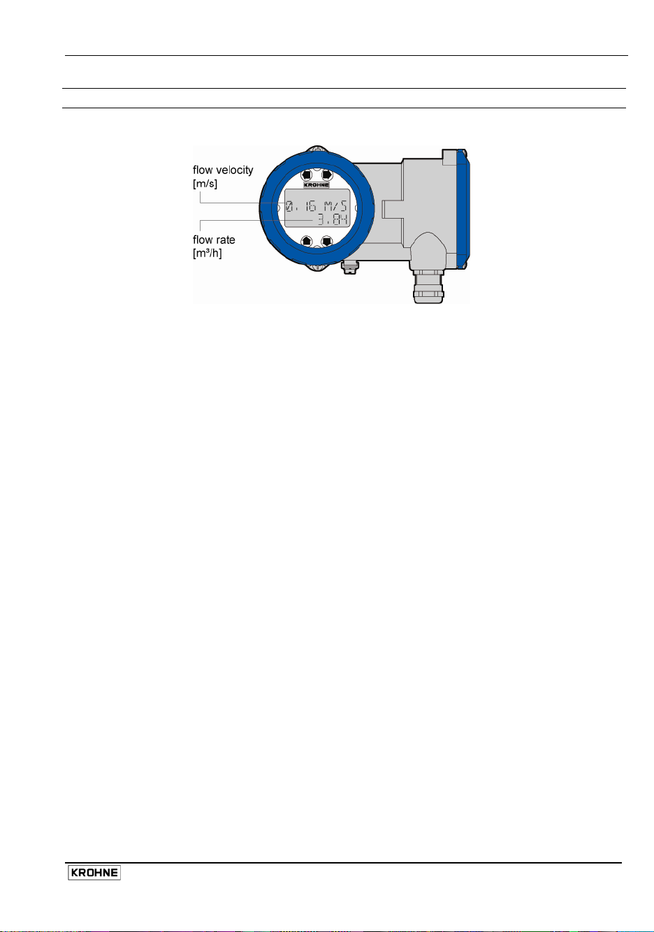
1 Display data in operating mode
Operating Instructions DWM 2000 D 3
Page 4

2 Functions of the LCD indicator for the DWM 2000 D
2.1 Programmable parameters
2.1.1 Flow calibration
can be modified in menu 2.1.3 in order to obtain the maximum accuracy at operating
The G
K
conditions. A field calibration requires an accurate reference of velocity. The meter recalibration (G
modification) is also recommended after an exchange of electronics module.
The value of the new calibration constant (GK new) can be calculated as follows:
GK
Vm
with:
Va = actual velocity
Vm = measured velocity (reference value)
2.1.2 Current output adjustment
The minimum value (i
conditions can be adjusted from menus 2.2.2. and 2.2.3.
The actual values of the i0% and the i
4...20 mA loop.
i0% must be in the range 3....12 mA. The factory setting is 4 mA.
i
must be in the range 12....21 mA. The factory setting is 20 mA.
100%
2.1.3 Time constant
The time constant value can be set in menu 2.2.4. This value represents the time needed to detect
63% of a simulated flow rate instantaneously raised from 0 to 100%. Time constant range : 5, 10,
15, 20, 25, 30, 50 m.
new = GKold x Va
) and the maximum value (i
0%
must be measured with an accurate milliammeter in a
100%
) of the current output at normal operating
100%
K
4 Operating Instructions DWM 2000 D
Page 5

2.2 Electronics module checks
Various parameters from the electronics module can be viewed directly for troubleshooting
purposes.
The DWM 2000 switches to alarm mode when the current output is permanently below 3 mA. In this
case the current output value indicates the type of error that occurs:
Obey the instructions that follow to find faults and the corrective actions to be undertaken.
Call up the error messages (menu 1.2.2.) and note the last one.
Refer to the error message list. Replace the electronics module in case of fatal error, deactivate the
alarm mode in menu 1.2.1. or the alarm count in menu 1.2.4 (in case of minor error).
CAUTION
Make sure that the instrument is correctly grounded.
Install the instrument in the sequence given in the installation manual.
A bad mechanical or electrical connection will cause the DWM 2000 to operate
incorrectly.
2.3 Programming structure (Software n° 1.02)
2.3.1 User interface buttons
Operating Instructions DWM 2000 D 5
Page 6

2.3.2 Menu navigation
Go through the steps given in the illustrations that follow to get to the required menu.
6 Operating Instructions DWM 2000 D
Page 7

Operating Instructions DWM 2000 D 7
Page 8

2.3.3 Summary of programming menus
Fct. n° Text Description and settings
1.0.0. TEST Main menu 1.0.0.
1.1.0. CHECK ALL Sub menu 1.1.0. for check of electronic components
1.1.1. MAG. FEQ. Frequency of magnetic field
10 Hz ≤ frequency ≤ 14.5 Hz, operating mode
1.1.2. FULL SCALE Programmed full scale
1 m/s ≤ full scale ≤ 8 m/s
1.1.3. U REF Internal voltage reference
U Ref. = 2.5 V
1.1.4. AMPLI Test value of amplifier control loop
Value ≥ 40 in test mode
1.1.5. EEP CHECKS Result of data check in EEPROM
“XXX”: measured value = test has been successful
“XXX + ALARM”: test has failed and alarm mode has been
activated (current output value < 4 mA).
1.1.6. EP CHECKS Result of data check in EEPROM
Value = 22309
1.1.7. ZERO KEY Result of zero calibration push button test
“OK”: test has been successful; “ALARM”: The test has failed
and alarm mode has been activated (current output < 4 mA).
This is only a test and does not reset the instrument to zero.
Refer to the installation manual to use the Zero Cal button on
the DWM 2000 electronics block correctly.
1.2.0. DIAGNOSTIC Sub menu 1.2.0. Diagnostic
1.2.1 ALARM MODE Deactivation of the alarm mode (current output < 4 mA) caused
by test failure (see menu 1.1.2. to 1.1.7).
“YES”: alarm mode is enabled
“NO”: alarm mode is disabled
1.2.2. REG FAIL. All the error messages that have occurred since the first powerup are listed. Maximum storage capacity: 32 messages
See section “2.5 Error Message List” for the meaning of error
messages.
1.2.3. TEST MODE Activation of PRODUCT (factory auto-diagnostic test mode) or
CUSTOM (field auto-diagnosis test mode = less severe).
Default setting: CUSTOM (field test mode)
1.2.4. ALARM COUNT Reset of the alarms counter
2.0.0. SET UP
PARAMETER
2.1.0. DATA BASE Sub menu 2.1.0. Base data
2.1.1. FULL SCALE Not available.
2.1.3. GK VALUE Primary head calibration constant 0.8 ≤ GK ≤ 1.300
2.1.4. CORRECTION Activation of the low flow linearization for velocity below 3 m/s.
Main menu 2.0.0.
See section “1.1.1. Flow calibration” on how to recalculate G
Select “YES” or “NO”, default setting:“YES”
.
K
8 Operating Instructions DWM 2000 D
Page 9

Fct. n° Text Description and settings
2.2.0. CURRENT OUT Sub menu 2.2.0. Current output
2.2.1. CURRENT? Not available
2.2.2. I 0% Calibrati on of the current output for i0%
Measure the exact value on a milliammeter and press the “+” or
“-” key in order to obtain the wished value for i0%
3 mA ≤ i
2.2.3. I 100% Calibration of the current output for i
Measure the exact value on a milliammeter and press the “+” or
“-” key in order to obtain the wished value for i
12 mA ≤ i
2.2.4. TIME CONST. Time constant for output of the measured values
Range: 5, 10, 15, 20, 25, 30, 50 m
2.4.0. SPECIAL Sub menu 2.4.0. Special functions
2.4.1. LANGUAGE Language for display text
“GB”: English
“F”: French
“D”: German
2.4.2. PASSWORD Not available
2.4.3. EEP PARAM. Display of the different parameters memorised in the
EEPROM: see section “2.4 Parameters Stored in the
EEPROM”. Read only.
2.4.4. FILTER Activation of an electronic filter for noisy applications
(foam, solid contents).
Select “YES” or “NO”, default setting “YES”.
2.4.5. DISPLAY Display of the actual velocity in m/s. The velocity is displayed
after quitting the programming menu.
Select “YES” or “NO”. Default setting “NO”.
It must be programmed to “NO” before you disconnect the
DWM 2000 D.
2.4.6. DIAMETER Diameter of the pipe into which the sensor is inserted. This
value is needed for calculating the flow rate. If you enter a
value of “0”, this switches off flow rate on the indicator display.
Refer also to the CAUTION that follows.
50 mm ≤ diameter ≤ XXXX mm
CAUTION
Do not use menu 2.4.6 to read the setting for the pipe d iameter. This will reset
the value to default “0” and switch off the flow rate line on the indicator
display. Use menu 2.4.3 to read EEPROM settings (this includes DIAMETER).
If the value is reset to “0”, you must re-enter the pipe diameter in menu 2.4.6.
≤ 12 mA
0%
100%
≤ 21 mA
100%
100%
Operating Instructions DWM 2000 D 9
Page 10

r
2.4 Parameters stored in the EEPROM (menu 2.4.3)
Paramete
CHECKS 1 Check EEPROM n°1 CHECKS 2 Check EEPROM n°2 CHECKS BYTE 1 Check EEPROM CHECKS BYTE 2 Check EEPROM CPT ALARM. Counting of all the error messages
CPT ALARM.2: Counting of all the error messages
TEST Indication of auto diagnostic test
CORRECTION
YES/NO
EP CHECKS Result of the d ata check in EPROM
FS Display of the programmed full scale
GK Primary head calibration constant
U REF Internal voltage reference
T CST Time constant (see menu 2.2.4.) 5 s
TEST AMP Test value of the amplifier control
FM Frequency of the magnetic field
DIAMETER Diameter of pipeline
Comment Typical value
-
since the first power-up.
-
since the last reset.
CUSTOM
level
Indication of activation of low velocity
linearization.
(see menu 1.1.6.)
values (see menu 1.1.2.)
(see menu 2.1.3.)
(see menu 1.1.3.)
loop (see menu 1.1.4.)
(see menu 1.1.1.)
(see menu 2.4.6)
YES
Value = 22309
With soft V1.02
1 m/s ... 8 m/s
0.8 ... 1.3
2.4. ... 2.6.
75 ... 95
10 ... 14.5 Hz
≥ 50 mm
10 Operating Instructions DWM 2000 D
Page 11

A
2.5 Error message list
Listed below are the messages which can appear in menu 1.2.2. This function stores all the faults
that have occurred since the first connection to power.
Error
messages
MAG. FREQ
AMPLI
F.S.
ZERO KEY
EP CHECK
EEP CHECK
U REF
CURR. OUT
FS SWIT EEP
ZERO
Comment
No magnetic field frequency out of range
10 Hz ≤ frequency ≤ 14.5 Hz
Dysfunction of the amplifier loop
Programmed full scale out of range
(>8 m/s or <1 m/s).
Dysfunction of ZERO key (short circuit) Replace the electronics module
Data loss in EPROM (software) Repl ace the electronics module
Data loss in EEPROM (calibration and
calculation data)
Amplifier voltage reference is damaged Replace the electronics module
Incorrect position of the internal current output
switch
Modification of the full scale power on Program the full scale power off
Velocity measurement during the zero
adjustment is more than 0.2 m/s.
ctions
Replace the electronics module
Replace the electronics module
Replace the electronics module
Replace the electronics module
Replace the electronics module
Deactivate the alarm mode and
adjust the zero again
Operating Instructions DWM 2000 D 11
Page 12

DWM 2000 D
nn
nnnnnnnnnnnnnnnnnnnnnnnnnnnnnnnnnnnnnnnnn
KROHNE measuring technology - Product overview
• Electromagnetic flowmeters • Level measuring instruments
• Variable area flowmeters • Temperature measuring instruments
• Mass flowmeters • Pressure measuring instruments
• Ultrasonic flowmeters • Analysis
• Vortex flowmeters • Oil and gas industry
• Flow controllers
Addresses:
Germany
Northern sales office
KROHNE Messtechnik GmbH & Co. KG
Bremer Str. 133
D-21073 Hamburg
Phone:+49 (0)40 767 3340
Fax:+49 (0)40 767 33412
nord@krohne.com
ZIP code: 10000 - 29999, 49000 - 49999
Western and middle sales office
KROHNE Messtechnik GmbH & Co. KG
Ludwig-Krohne-Straße
D-47058 Duisburg
Phone:+49 (0)203 301 4416
Fax:+49 (0)203 301 10416
west@krohne.de
ZIP code: 30000 - 34999, 37000 48000, 50000 - 53999, 57000 - 59999,
98000 - 99999
Southern sales office
KROHNE Messtechnik GmbH & Co. KG
Landsberger Str. 392
D-81241 Munich
Phone:+49 (0)89 121 5620
Fax:+49 (0)89 129 6190
sued@krohne.com
ZIP code: 0 - 9999, 80000 - 89999,
90000 - 97999
Southwestern sales office
KROHNE Messtechnik GmbH & Co. KG
Rüdesheimer Str. 40
D-65239 Hochheim/Main
Phone: +49(0)6146) 827 30
Fax:+49 (0)6146 827 312
rhein-main@krohne.com
ZIP code: 35000 - 36999, 54000 56999, 60000 - 79999
Instrumentation and control
equipment catalog
TABLAR Messtechnik GmbH
Ludwig-Krohne-Straße 5
D-47058 Duisburg
Phone:+49 (0)2 03 305 880
Fax:+49 (0)2 03 305 8888
kontakt@tablar.de; www.tablar.de
KROHNE sales
companies
International
Australia
KROHNE Australia Pty Ltd
Quantum Business Park 10/287
Victoria Rd Rydalmere NSW 2116
Phone: +61 2 8846 1700
Fax: +61 2 8846 1755
krohne@krohne.com.au
Austria
KROHNE Gesellschaft m.b.H.
Modecenterstraße 14
A-1030 Vienna
Phone:+43 (0)1/203 45 32
Fax:+43 (0)1/203 45 32 99
info@krohne.at
Belgium
KROHNE Belgium N.V.
Brusselstraat 320
B-1702 Groot Bijgaarden
Phone:+32 (0)2 4 66 00 10
Fax:+32 (0)2 4 66 08 00
krohne@krohne.be
Brazil
KROHNE Conaut Controles
Automaticos Ltda.
Estrada Das Águas Espraiadas, 230
C.P. 56 06835 - 080 EMBU - SP
Phone:+55 (0)11-4785-2700
Fax:+55 (0)11 4785-2768
conaut@conaut.com.br
China
KROHNE Measurement Instruments
(Shanghai) Co. Ltd., (KMIC)
9th Floor, Xujiahui International
Building
1033 Zhaojiabang Road
Shanghai 200030
Phone: +86 21 6487 9611
Fax:+86 21 6438 7110
info@krohne-asia.com
Czech Republic
Krohne CZ, spol. s r.o.
Sobìsická 156
63800 Brno
Phone: +420 (0)545.242 627
Fax: +420 (0)545 220 093
brno@krohne.cz
France
KROHNE S.A.S.
Les Ors BP 98
F-26103 ROMANS Cedex
Phone:+33 (0)4 75 05 44 00
Fax:+33 (0)4 75 05 00 48
info@krohne.fr
Great Britain
KROHNE Ltd.
Rutherford Drive
Park Farm Industrial Estate
Wellingborough
Northants NN8 6AE
Phone:+44 (0)19 33 408 500
Fax:+44 (0)19 33 408 501
info@krohne.co.uk
CIS
Kanex KROHNE Engineering AG
Business-Centre Planeta
Office 404 ul.
Marxistskaja 3
109147 Moscow/Russia
Phone:+7 (0)095 911 7165
Fax:+7 (0)095 742 8873
krohne@dol.ru
India
Krohne Marshall Ltd.
A-34/35, M.I.D.C. Industrial Area,
H-Block
Pimpri Poona 411018
Phone:+91 (0)202 744 2020
Fax:+91 (0)202 744 2020
pcu@vsnl.net
Iran
KROHNE Liaison Office
North Sohrevardi Ave. 26,
Sarmad St., Apt. #9
Tehran 15539
Phone: +9821 8874 5973
Fax: +9821 8850 1268
krohne@krohneiran.com
Italy
KROHNE Italia Srl.
Via V. Monti 75
I-20145 Milan
Phone:+39 02 4300 661
Fax:+39 02 4300 6666
info@krohne.it
Korea
KROHNE Korea
Room 508 Miwon Bldg 43
Yoido-Dong Youngdeungpo-Ku
Seoul, Korea
Phone: 00-82-2-782-1900
Fax: 00-82-2-780-1749
mail@krohne.co.kr
Netherlands
KROHNE Nederland B.V.
Kerkeplaat 14
NL-3313 LC Dordrecht
Phone:+31 (0)78 630 6200
Fax:+31 (0)78 630 6405
Service Direct: +31 (0)78 630 6222
info@krohne.nl
Norway
KROHNE Norway A.S.
Ekholtveien 114
NO-1521 Moss
Phone:+47 (0)69 264 860
Fax:+47 (0)69 267 333
postmaster@krohne.no
Poland
KROHNE Polska Sp.z.o.o.
ul. Stary Rynek Oliwski 8a
80-324 Gdansk
Phone: +48 (0)58 520 9211
Fax.:+48 (0)58 520 9212
info@krohne.pl
Switzerland
KROHNE AG
Uferstr. 90
CH-4019 Basel
Phone:+41 (0)61 638 30 30
Fax:+41 (0)61 638 30 40
info@krohne.ch
Singapore
Tokyo Keiso - KROHNE (Singapore)
Pte. Ltd.
14, International Business Park,
Jurong East
Chiyoda Building, #01-01/02
Singapore 609922
Phone: (65) 6567 4548
Fax : (65) 6567 9874
tks@tokyokeiso-krohne.com.sg
Republic of South Africa
KROHNE Pty. Ltd.
Bushbock Close
Corporate Park South
Midrand, Gauteng
P.O. Box 2069
Midrand, 1685
Tel.: +27 (0)11 314 1391
Fax: +27 (0)11 314 1681
midrand@krohne.co.za
Spain
I.I. KROHNE IBERIA, S.r.l.
Poligono Industrial Nilo
Calle Brasil, nº. 5
28806 Alcalá de Henares Madrid
Phone: +34 (0)91 883 2152
Fax: +34 (0)91 883 4854
krohne@krohne.es
USA
KROHNE, Inc.
7 Dearborn Road
Peabody, MA 01960
Phone: +1 (800) FLOWING
Phone: +1 (978) 535 6060 (in MA)
info@krohne.com
Representatives
Algeria
Argentina
Cameroon
Canada
Chile
Columbia
Croatia
Denmark
Ecuador
Egypt
Finland
Gabon
Ghana
Greece
Hong Kong
Hungary
Indonesia
Iran
Ireland
Israel
Ivory Coast
Japan
Jordan
Kuwait
Libya
Lithuania
Malaysia
Mauritius
Mexico
Morocco
New Zealand
Peru
Portugal
Romania
Saudi Arabia
Senegal
Slovakia
Slovenia
Sweden
Taiwan
Thailand
Tunisia
Turkey
Venezuela
Yugoslavia
Other countries
KROHNE Messtechnik GmbH & Co. KG
Ludwig-Krohne-Str. 5
D-47058 Duisburg
Phone:+49 (0)203 301 0
Fax:+49 (0)203 301 389
export@krohne.de
© KROHNE 04/2008 Subject to change without notice
www.krohne.com
 Loading...