

Page 1
Supplementary instructions
Supplementary instructions
DW 18 SERIES
DW 18 SERIES
DW 18 SERIESDW 18 SERIES
Supplementary instructions Supplementary instructions
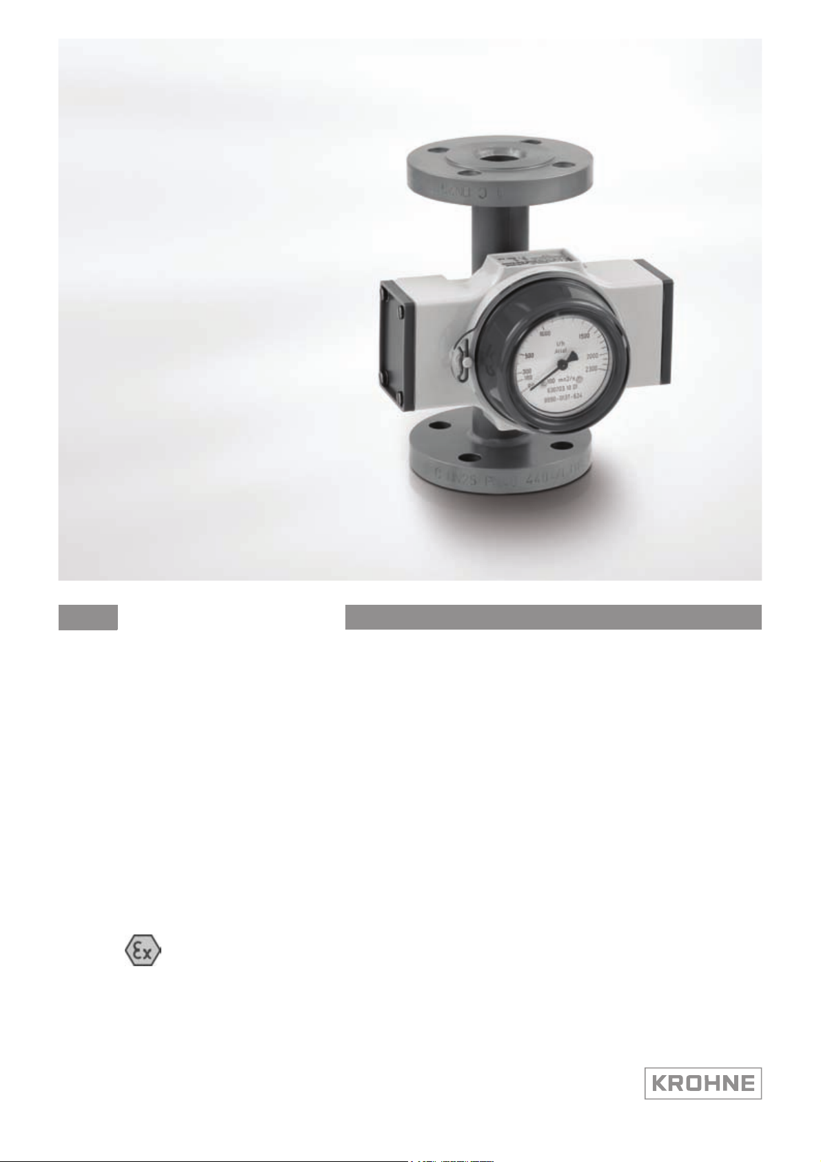
Mechanical Flow Controller
Supplementary Instructions for ATEX applications
Supplementary Instructions for ATEX applications
Supplementary Instructions for ATEX applicationsSupplementary Instructions for ATEX applications
© KROHNE 11/2011 - 4001528201 - AD ATEX DW181-184 R01 en
Page 2

CONTENTS
DW 18 SERIES
1 General safety information 3
1.1 Scope ................................................................................................................................ 3
1.2 Device description ............................................................................................................ 3
1.3 Standards and approvals.................................................................................................. 3
1.4 Device categories ............................................................................................................. 4
1.4.1 Ex c-approved devices ............................................................................................................ 4
1.4.2 Ex ia-approved devices ........................................................................................................... 4
1.4.3 Ex d- / Ex tb-approved devices ...............................................................................................4
1.4.4 Definitions of device categories.............................................................................................. 5
1.5 Equipment protection levels (EPL)................................................................................... 5
1.5.1 Ex ia-approved devices ........................................................................................................... 5
1.5.2 Ex d- / Ex tb-approved devices ...............................................................................................5
1.5.3 Definitions of equipment protection levels ............................................................................ 5
1.6 Nameplates ...................................................................................................................... 5
1.6.1 ATEX nameplates .................................................................................................................... 6
1.6.2 Other labels............................................................................................................................. 8
2 Installation 9
2.1 Special conditions for safe use ........................................................................................ 9
2.2 Operating conditions: ambient and process temperature ............................................ 10
3 Electrical connections 11
3.1 General notes ................................................................................................................. 11
3.2 Ex c equipment ............................................................................................................... 11
3.3 Ex ia equipment .............................................................................................................. 11
3.3.1 How to connect the electrical cables ................................................................................... 11
3.3.2 Maximum intrinsically-safe values for the electrical circuit............................................... 11
3.3.3 Electrical schematics............................................................................................................ 12
3.4 Ex d / Ex tb equipment.................................................................................................... 13
3.4.1 General notes........................................................................................................................ 13
3.4.2 How to connect the electrical cables ................................................................................... 13
3.4.3 Maximum switching capacity values for the electrical circuit............................................. 13
3.4.4 Electrical schematics............................................................................................................ 13
4 Start-up 14
5 Service 15
5.1 Periodic maintenance..................................................................................................... 15
5.2 Returning the device to the manufacturer..................................................................... 15
5.2.1 General information.............................................................................................................. 15
5.2.2 Form (for copying) to accompany a returned device............................................................ 16
6 Notes 17
2
www.krohne.com 11/2011 - 4001528201 - AD ATEX DW181-184 R01 en
Page 3
DW 18 SERIES
1.1 Scope
These instructions are applicable only to devices that have one of the two application options for
use in hazardous areas (intrinsically-safe and explosion-proof devices). For all other data, use
the Quick Start and Handbook for the DW 18 series flow switch. If you do not have these
documents, please contact the nearest sales office or download them from the website
www.krohne.com.
WARNING!
Installation, commissioning and maintenance may only be carried out by "Personnel trained in
explosion protection".
INFORMATION!
The information in this ATEX supplement only contains the data applicable to explosion
protection. The technical data in the installation and operating manual for the non-Ex version
shall be valid in its current version, provided that they are not rendered invalid or are replaced by
this ATEX supplement.
1.2 Device description
GENERAL SAFETY INFORMATION 1
DW 181 - 184 flow switches are mechanical devices that use a hinged, spring-loaded metal disc
to measure the flow rate of homogenous, clean liquids. Adjustable switches in the device
operate an alarm when you have the correct flow rate or velocity.
Several variants (DW181, DW182 etc.) are available for a wide range of pipe diameters. Each
variant has display and application options.
The flow switch is approved for use in potentially explosive atmospheres when equipped with the
appropriate options.
1.3 Standards and approvals
DANGER!
In compliance with European Directive 94/9/EC (ATEX 100a), the ATEX version of the device
described in these Supplementary Instructions conforms to European Standards EN 600790:2009, EN 60079-1:2007, EN 60079-11:2007, prEN 60079-11:2011, EN 60079-31:2009,
EN 13463-1:2009 and EN 13463-5:2004. The Ex ia, Ex d and Ex c versions are certified for use in
hazardous areas by INERIS under INERIS 03ATEX0045 X.
WARNING!
Carefully read the ATEX approval certificate. Obey the boundary conditions.
The certificate is given on the CD-ROM supplied with the device. You can also download the
certificate from our internet site.
www.krohne.com11/2011 - 4001528201 - AD ATEX DW181-184 R01 en
3
Page 4

1 GENERAL SAFETY INFORMATION
1.4 Device categories
1.4.1 Ex c-approved devices
The Ex c-approved device does not have a switch option. It only has an indicator.
The Ex c-approved device is suitable for use in potentially explosive atmospheres of all
flammable substances in Apparatus Group IIC. It is certified for applications requiring Category
1 G (gases, vapours or mists) or 1 D (dust) equipment when fitted with the appropriate options.
1.4.2 Ex ia-approved devices
Ex ia-approved devices have these switch options:
• K1 (1 × N/C (normally closed) switch or 1 × N/O (normally open) switch)
• K2 (2 × N/C switches or 2 × N/O switches)
• K2 (1 × N/C and 1 × N/0 switches or 1 × N/O and 1 × N/C switches)
• K1 changeover (1 × 3-wire SPDT switch)
• K2 changeover (2 × 3-wire SPDT switches)
DW 18 SERIES
The Ex ia-approved device is suitable for use in potentially explosive atmospheres of all
flammable substances in Apparatus Groups IIC and IIIC. It is certified for applications requiring
Category 1 G (gases, vapours or mists), or 1 D (dust) equipment when fitted with the appropriate
options.
INFORMATION!
The mechanical part of the assembly is Ex c-approved.
1.4.3 Ex d- / Ex tb-approved devices
Ex d- / Ex tb-approved devices have these switch options:
• K1 (1 × N/C switch)
• K1 (1 × N/O switch)
• KV1 (1 × N/O switch with relay)
The Ex d- and Ex tb-approved devices are suitable for use in potentially explosive atmospheres
of all flammable substances in Apparatus Groups IIC and IIIC. It is certified for applications
requiring Category 1/2 G (gases, vapours or mists) or 1/2 D (dust) equipment when fitted with the
appropriate options.
INFORMATION!
The mechanical part of the assembly is Ex c-approved.
4
www.krohne.com 11/2011 - 4001528201 - AD ATEX DW181-184 R01 en
Page 5

DW 18 SERIES
GENERAL SAFETY INFORMATION 1
1.4.4 Definitions of device categories
Category 1
Category 1
Category 1Category 1
The device is installed in hazardous areas requiring Category 1 G or 1 D equipment.
Category 1/2
Category 1/2
Category 1/2Category 1/2
The switch housing is installed in hazardous areas requiring Category 2 G or 2 D equipment. The
measuring tube is installed in hazardous areas requiring Category 1 G or 1 D equipment.
1.5 Equipment protection levels (EPL)
1.5.1 Ex ia-approved devices
The Ex ia-approved device is certified for applications for which an EPL of Ga or Da is necessary.
1.5.2 Ex d- / Ex tb-approved devices
The Ex d-approved device is suitable is certified for applications for which an EPL of Gb or Db is
necessary.
1.5.3 Definitions of equipment protection levels
EPL Ga or Da
EPL Ga or Da
EPL Ga or DaEPL Ga or Da
The device is installed in hazardous areas that must have equipment with a very high level of
protection. The device is not a source of ignition in usual conditions of operation or when
possible or unusual faults occur.
EPL Gb or Db
EPL Gb or Db
EPL Gb or DbEPL Gb or Db
The device is installed in hazardous areas that must have equipment with a high level of
protection. The device is not a source of ignition in usual conditions of operation or when
possible faults occur. It is possible that this does not include frequent faults.
1.6 Nameplates
INFORMATION!
Look at the device nameplate to ensure that the device is delivered according to your order.
Check for the correct supply voltage printed on the nameplate.
www.krohne.com11/2011 - 4001528201 - AD ATEX DW181-184 R01 en
5
Page 6
1 GENERAL SAFETY INFORMATION
1.6.1 ATEX nameplates
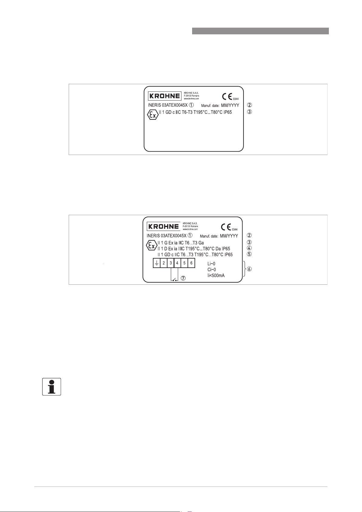
Figure 1-1: Ex c nameplate
1 ATEX certification agency code
2 Year made
3 Gas group, equipment approval category (explosive atmosphere - gas or dust), types of device protection, temperature
classes (T6...T3), maximum surface temperature and degree of ingress protection (if fitted with the appropriate cable
glands)
DW 18 SERIES
Figure 1-2: Ex ia nameplate
1 ATEX certification agency code
2 Year made
3 Gas group, equipment approval category (explosive atmosphere - gas), types of device protection including apparatus
groups, temperature classes (T6...T3) and equipment protection level
4 Gas group, equipment category (explosive atmosphere - dust), types of device protection including apparatus groups,
maximum surface temperature, equipment protection level and degree of ingress protection (if fitted with the appropriate cable glands)
5 Mechanical parts only:
Mechanical parts only: Gas group, equipment approval category (explosive atmosphere - gas or dust), types of device
Mechanical parts only:Mechanical parts only:
protection, temperature classes (T6...T3), maximum surface temperature and degree of ingress protection (if fitted
with the appropriate cable glands)
6 Maximum intrinsically-safe values for the electrical circuit
7 Electrical schematic (type of switch, number of switches and switch position)
INFORMATION!
Cable entry data for Ex i-approved devices is given on the standard device nameplate.
½
Cable entry options: PG13.5, M20×1.5 or
NPT
6
www.krohne.com 11/2011 - 4001528201 - AD ATEX DW181-184 R01 en
Page 7

DW 18 SERIES
Figure 1-3: Ex d nameplate
1 Limit switch code
2 Year made
3 ATEX certification agency code
4 Gas group, equipment approval category (explosive atmosphere - gas), types of device protection including apparatus
5 Gas group, equipment category (explosive atmosphere - dust), types of device protection including apparatus groups,
6 Mechanical parts only:
7 Factory order number
8 Maximum switching capacity
9 Electrical schematic (type of switch, number of switches and switch position)
10 Cable entry type and size (Cable entry options: M20×1.5 or ¾ NPT)
GENERAL SAFETY INFORMATION 1
groups, temperature classes (T6...T3) and equipment protection level
maximum surface temperature, equipment protection level and degree of ingress protection (if fitted with the appropriate cable glands)
Mechanical parts only: Gas group, equipment approval category (explosive atmosphere - gas or dust), types of device
Mechanical parts only:Mechanical parts only:
protection, temperature classes (T6...T3), maximum surface temperature and degree of ingress protection (if fitted
with the appropriate cable glands)
www.krohne.com11/2011 - 4001528201 - AD ATEX DW181-184 R01 en
7
Page 8

1 GENERAL SAFETY INFORMATION
1.6.2 Other labels
ESD warning sticker
PLASTIC PARTS
WARNING:
POTENTIAL ELECTROSTATIC HAZARD
!
SEE INSTRUCTIONS
Figure 1-4: ESD warning sticker (below the device nameplate)
1 Text: Plastic Parts
2 Text: Warning! Potential electrostatic hazard - see instructions
DW 18 SERIES
For more data, refer to
Special conditions for safe use
on page 9.
Warning sticker for Ex d-approved devices
Figure 1-5: Warning sticker for Ex d-approved devices
1 Text (in French and English): Warning - Do not open while energized
For more data, refer to
Ex d / Ex tb equipment
on page 13.
8
www.krohne.com 11/2011 - 4001528201 - AD ATEX DW181-184 R01 en
Page 9

DW 18 SERIES
2.1 Special conditions for safe use
WARNING!
When you install the device, obey the conditions in the EC-Type Examination certificate. These
conditions include:
•
The special conditions for safe use.
•
The Essential Health and Safety Requirements.
DANGER!
This installation must agree with EN 60079-14: Explosive atmospheres - Part 14: Electrical
installations design, selection and erection and EN 61241-14: Electrical apparatus for use in the
presence of combustible dust - Part 14: Selection and installation or other applicable
international standards.
DANGER!
Electrostatic discharge
Electrostatic discharge
Electrostatic dischargeElectrostatic discharge
Risk of electrostatic discharge from plastic parts. Make sure that all personnel and equipment
are correctly grounded.
INSTALLATION 2
Take the necessary antistatic precautions if you:
• handle,
• install or
• use
the device in potentially explosive atmospheres. Do not install in a location (near to ventilation
systems, for example) where the electrostatic charge can increase.
www.krohne.com11/2011 - 4001528201 - AD ATEX DW181-184 R01 en
9
Page 10

2 INSTALLATION
2.2 Operating conditions: ambient and process temperature
The allowable ambient temperature and corresponding flange temperature range for the device
depends on the equipment category, equipment protection level (EPL) and temperature classes
marked on the nameplate.
The equipment category, equipment protection level and temperature class give the ambient
temperature and related process temperature ranges for the device.
-40°C / -40°F is the minimum ambient temperature for all application options for use in
hazardous areas.
Equipment category 1 G or EPL Ga: Ex ia devices
Equipment category 1 D or EPL Da: Ex ia devices
DW 18 SERIES
Temperature class Maximum ambient
temperature
[°C] [°F] [°C] [°F]
T6 +40 +104 +60 +140
T5 +40 +104 +80 +176
T4 +60 +140 +120 +248
T3 +80 +176 +150 +302
Equipment category 1/2 G or EPL Gb: Ex d devices
Equipment category 1/2 D or EPL Db: Ex tb devices
Temperature class Maximum ambient
temperature
[°C] [°F] [°C] [°F]
T6 +50 +122 +60 +140
T5 +50 +122 +80 +176
T4 +60 +140 +120 +248
T3 +80 +176 +150 +302
Equipment category 1 G: Ex c devices
Equipment category 1 D: Ex c devices
Maximum process
temperature
Maximum process
temperature
10
Temperature class Maximum ambient
temperature
[°C] [°F] [°C] [°F]
T6 +40 +104 +60 +140
T5 +40 +104 +80 +176
T4 +60 +140 +120 +248
T3 +80 +176 +150 +302
www.krohne.com 11/2011 - 4001528201 - AD ATEX DW181-184 R01 en
Maximum process
temperature
Page 11

DW 18 SERIES
3.1 General notes
WARNING!
•
Use the applicable cable glands for the cable entry openings in the housing.
•
If ambient temperature >70°C / >158°F, use heat-resistant cables, cable glands and cable
entry plugs certified for continuous operation above +80
•
De-energize the circuit.
3.2 Ex c equipment
The Ex c-approved device does not have a switch option.
3.3 Ex ia equipment
3.3.1 How to connect the electrical cables
INFORMATION!
Cable entries are supplied on customer demand. If you supply the cable entries, this part must
have a degree of ingress protection IP≥65 (EN 60529).
ELECTRICAL CONNECTIONS 3
°
C / +176°F.
• Use the electrical connection procedure in the Handbook.
• Supply the Ex i equipment connected to the device. Use only certified intrinsically-safe
equipment.
• Connect only to separate certified, intrinsically-safe circuits. Make sure that the electrical
circuit characteristics are not more than the values that follow.
3.3.2 Maximum intrinsically-safe values for the electrical circuit
• Ui is not given
≤500 mA
• I
i
=0 nF
• C
i
=0 µH
• L
i
Voltage is not given, but U and I must be intrinisically safe.
www.krohne.com11/2011 - 4001528201 - AD ATEX DW181-184 R01 en
11
Page 12

3 ELECTRICAL CONNECTIONS
3.3.3 Electrical schematics
DW 18 SERIES
Figure 3-1: Electrical schematics for Ex ia-approved equipment (switch options)
1 K1: 1 × N/O (normally open) switch
2 K1: 1 × N/C (normally closed) switch
3 K2: 2 × N/O switches
4 K2: 2 × N/C switches
5 K2: 1 × N/O and 1 × N/C switches
6 K2: 1 × N/C and 1 × N/0 switches
7 K1 changeover: 1 × 3-wire SPDT switch
8 K2 changeover: 2 × 3-wire SPDT switches
12
www.krohne.com 11/2011 - 4001528201 - AD ATEX DW181-184 R01 en
Page 13

DW 18 SERIES
ELECTRICAL CONNECTIONS 3
3.4 Ex d / Ex tb equipment
3.4.1 General notes
DANGER!
Do not open the housing while the device is energized.
3.4.2 How to connect the electrical cables
INFORMATION!
Cable entries are supplied on customer demand. If you supply the cable entries, this part must
have a degree of ingress protection IP≥65 (EN 60529).
WARNING!
Use only Ex d-approved cable entries and plugs for Ex d applications. Use only Ex t-approved
cable entries and plugs for Ex t applications.
¨
Do not remove more than 6 mm / 0.2
3.4.3 Maximum switching capacity values for the electrical circuit
of insulation from the wire.
• U
• P
max
= 20VA
c
= 380 V
3.4.4 Electrical schematics
Figure 3-2: Electrical schematics for Ex d-approved equipment (switch options)
1 K1: 1 × N/O (normally open) switch
2 K1: 1 × N/C (normally closed) switch
3 KV1: 1 × N/O switch with amplifier relay
www.krohne.com11/2011 - 4001528201 - AD ATEX DW181-184 R01 en
13
Page 14

4 START-UP
Do a start-up check:
• Are the wetted components (gasket, measuring tube and measuring disc) resistant to
corrosion by the tank product?
• Does the information given on the nameplate agree with the application?
DW 18 SERIES
14
www.krohne.com 11/2011 - 4001528201 - AD ATEX DW181-184 R01 en
Page 15

DW 18 SERIES
5.1 Periodic maintenance
DANGER!
Make sure that maintenance operations agree with EN 60079-17: Explosive atmospheres - Part
17: Electrical installations inspection and maintenance.
5.2 Returning the device to the manufacturer
5.2.1 General information
This device has been carefully manufactured and tested. If installed and operated in accordance
with these operating instructions, it will rarely present any problems.
CAUTION!
Should you nevertheless need to return a device for inspection or repair, please pay strict
attention to the following points:
•
Due to statutory regulations on environmental protection and safeguarding the health and
safety of our personnel, manufacturer may only handle, test and repair returned devices that
have been in contact with products without risk to personnel and environment.
•
This means that the manufacturer can only service this device if it is accompanied by the
following certificate (see next section) confirming that the device is safe to handle.
SERVICE 5
CAUTION!
If the device has been operated with toxic, caustic, flammable or water-endangering products,
you are kindly requested:
•
to check and ensure, if necessary by rinsing or neutralizing, that all cavities are free from
such dangerous substances,
•
to enclose a certificate with the device confirming that is safe to handle and stating the
product used.
www.krohne.com11/2011 - 4001528201 - AD ATEX DW181-184 R01 en
15
Page 16

5 SERVICE
5.2.2 Form (for copying) to accompany a returned device
Company: Address:
Department: Name:
Tel. no.: Fax no.:
Manufacturer's order no. or serial no.:
The device has been operated with the following medium:
DW 18 SERIES
This medium is: water-hazardous
toxic
caustic
flammable
We checked that all cavities in the device are free from such
substances.
We have flushed out and neutralized all cavities in the
device.
We hereby confirm that there is no risk to persons or the environment through any residual media
contained in the device when it is returned.
Date: Signature:
Stamp:
16
www.krohne.com 11/2011 - 4001528201 - AD ATEX DW181-184 R01 en
Page 17

DW 18 SERIES
NOTES 6
www.krohne.com11/2011 - 4001528201 - AD ATEX DW181-184 R01 en
17
Page 18

6 NOTES
DW 18 SERIES
18
www.krohne.com 11/2011 - 4001528201 - AD ATEX DW181-184 R01 en
Page 19

DW 18 SERIES
NOTES 6
www.krohne.com11/2011 - 4001528201 - AD ATEX DW181-184 R01 en
19
Page 20

KROHNE product overview
• Electromagnetic flowmeters
• Variable area flowmeters
• Ultrasonic flowmeters
• Mass flowmeters
• Vortex flowmeters
• Flow controllers
• Level meters
• Temperature meters
• Pressure meters
• Analysis products
• Measuring systems for the oil and gas industry
• Measuring systems for sea-going tankers
Head Office KROHNE Messtechnik GmbH
Ludwig-Krohne-Str. 5
D-47058 Duisburg (Germany)
Tel.:+49 (0)203 301 0
Fax:+49 (0)203 301 10389
info@krohne.de
© KROHNE 11/2011 - 4001528201 - AD ATEX DW181-184 R01 en - Subject to change without notice.
The current list of all KROHNE contacts and addresses can be found at:
www.krohne.com
 Loading...