

Page 1
Supplementary instructions
Supplementary instructions
DK32 DK34
DK32 DK34
DK32 DK34DK32 DK34
Supplementary instructions Supplementary instructions
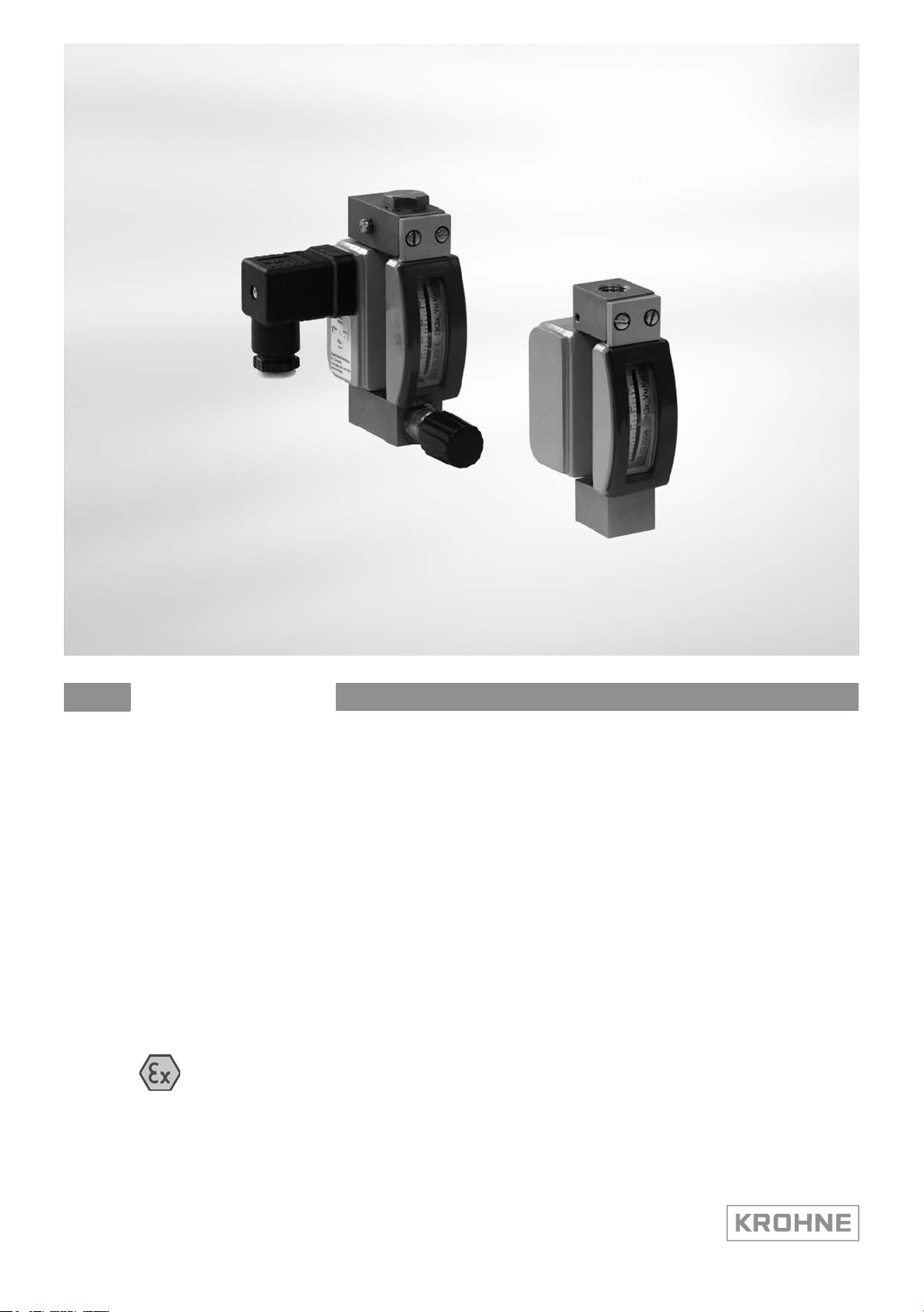
Variable area flowmeter
with electrical built-ins
Equipment category II 3 G
Equipment category II 3 G
Equipment category II 3 GEquipment category II 3 G
© KROHNE 03/2013 - 4002148602 AD DK32/34 II3G R03 en
Page 2

CONTENTS
DK32 DK34
1 Safety instructions 3
1.1 General notes ................................................................................................................... 3
1.2 EC conformity ................................................................................................................... 3
1.3 Security information......................................................................................................... 3
2 Device description 4
2.1 Device description ............................................................................................................ 4
2.2 Description code............................................................................................................... 4
2.3 Marking............................................................................................................................. 4
2.4 Flammable products ........................................................................................................ 5
2.5 Equipment category .........................................................................................................5
2.6 Protection types................................................................................................................ 6
2.7 Ambient temperature / temperature classes.................................................................. 7
2.8 Electrical data................................................................................................................... 8
3 Installation 9
3.1 Special conditions............................................................................................................. 9
3.2 Installation........................................................................................................................ 9
4 Electrical connections 10
4.1 General notes ................................................................................................................. 10
4.2 Earthing and equipotential bonding ............................................................................... 11
5 Operation 12
5.1 Start-up........................................................................................................................... 12
5.2 Operation ........................................................................................................................ 12
5.2.1 Operation as intrinsically safe equipment "ic"..................................................................... 12
5.2.2 Operation as non-sparking equipment "nA" ........................................................................ 12
6 Service 13
6.1 Maintenance ................................................................................................................... 13
6.2 Dismantling .................................................................................................................... 13
7 Notes 14
2
www.krohne.com 03/2013 - 4002148602 AD DK32/34 II3G R03 en
Page 3

DK32 DK34
1.1 General notes
These additional instructions apply to explosion-protected versions of variable area flowmeters
with electrical built-ins and the marking II 3 G. They complete the installation and operation
instructions for the non-explosion protected versions.
The information given in these instructions contains only the data relevant to category 3
explosion protection. The technical details given in the installation and operation instructions for
the non-explosion protected versions apply unchanged unless excluded or superseded by these
instructions.
1.2 EC conformity
The manufacturer declares with the EC Declaration of Conformity on his own responsibility
conformity with the protection goals of Directive 94/9/EC for use in hazardous areas with gas.
The assessment was made according to Directive 94/9/EC, Annex VIII (module "Internal control
of production"), and is registered company-internal under KMT-TDZ-A0121X. This registration
number is also provided on the nameplate.
SAFETY INSTRUCTIONS 1
1.3 Security information
Assembly, installation, start-up and maintenance may only be performed by personnel trained in
explosion protection!
CAUTION!
The operator respectively his agent is responsible to follow further standards, directives or laws
if required due to operating conditions or place of installation. This applies particularly for the
use of easy detachable process connections such as SMS or Clamp when measuring flammable
mediums.
www.krohne.com03/2013 - 4002148602 AD DK32/34 II3G R03 en
3
Page 4

2 DEVICE DESCRIPTION
2.1 Device description
Variable area flowmeters measure and display the volume flow of flammable and nonflammable gases and liquids. The display houses one or two separately adjustable electrical
limit switches.
2.2 Description code
The safety description code * consists of the following elements:
1 32 - with valve and horizontal connection / 34 without valve and vertical connection
2 RE - inlet pressure regulator / RA - outlet pressure regulator
3 K1 - one limit switch / K2 - two limit switches
4 S - plug connector / L - cable gland incl. cable
5 HT - high-temperature version
6 A - Limit switch tested for EC type approval or IECEx tested
7 Ex - Explosion-protected equipment
DK32 DK34
* positions which are not needed are omitted (no blank positions)
2.3 Marking
The marking of the entire device is on the display, where the following identification plate can be
found. An additional marking is located on the inside of the display with the serial number (SN or
P/A number).
1 Device type
2 Manufacturer
3 PED data
4 Sizing data: temperature & pressure rating
5 Ex data
6 Built-in equipment
7 Note manual
8 KROHNE website
4
www.krohne.com 03/2013 - 4002148602 AD DK32/34 II3G R03 en
Page 5
DK32 DK34
2.4 Flammable products
Atmospheric conditions
Atmospheric conditions
Atmospheric conditionsAtmospheric conditions
An explosive atmosphere is a mixture of air and flammable gases, vapours, mists or dusts under
atmospheric conditions. The following values define it T
-4°F...140°F and P
behaviour for most mixtures.
Operating conditions
Operating conditions
Operating conditionsOperating conditions
Variable area flowmeters operate outside of atmospheric conditions, which means that
explosion protection according to Directive 94/9/EC (ATEX) – regardless of the zone assignment
– is fundamentally not applicable due to the lack of key safety data for the interior of the
measuring section.
CAUTION!
Operation with flammable products is only permissible if no explosive fuel/air mixture is formed
on the interior of the flowmeter under operating conditions. The user is responsible for the safe
operation of the flowmeter with regard to the temperatures and pressures of the products used.
In case of operation with flammable products the measuring units must be included in the
periodic pressure tests of the system.
atm
DEVICE DESCRIPTION 2
= -20°C...+60°C /
atm
= 0.8...1.1bar. Outside of this range, no key data are available as to ignition
2.5 Equipment category
The flowmeters are designed in category II 3G according to EN 60079-0, EN 60079-11 and EN
60079-15 for use in zone 2.
INFORMATION!
Definition of Zone 2 according to EN 1127-1, Appendix B:
An area in which an explosive atmosphere as a result of the mixture of flammable substances in
the form of gas, steam or mist with air is not expected to occur under normal operation. If,
however, such an atmosphere does occur it only lasts for a brief period of time.
For more information see the chapter entitled "Flammable products".
www.krohne.com03/2013 - 4002148602 AD DK32/34 II3G R03 en
5
Page 6

2 DEVICE DESCRIPTION
2.6 Protection types
Variable area flowmeters can be operated as protection type "non-sparking" or "intrinsic safety
protection level ic". Explanations of the individual protection types appear below.
The variable area flowmeter is designed with protection type "non-sparking" in accordance with
EN 60079-15. Protection against explosion is ensured in that no sparking contacts or hot
surfaces lead to ignition under normal operating conditions.
DK32 DK34
The marking is: II 3G Ex nA IIC T6 Gc
The marking contains the following information:
The marking contains the following information:
The marking contains the following information:The marking contains the following information:
II
II Group II explosion protection
IIII
3333 Equipment category 3
GGGG Gas explosion protection
nA
nA Non-sparking equipment
nAnA
IIC
IIC Gas groups IIA, IIB, IIC
IICIIC
T6
T6 Temperature classes T6 ... T1
T6T6
Gc
Gc Equipment protection levels (EPL)
GcGc
II 3G Ex nA IIC T6 Gc
II 3G Ex nA IIC T6 GcII 3G Ex nA IIC T6 Gc
The variable area flowmeter is designed with protection type "intrinsic safety, protection level ic"
in accordance with EN 60079-11. The explosion protection is ensured by way of limiting the
current and voltage so that no energy capable of ignition can occur.
The marking is: II 3G Ex ic IIC T6 Gc
The marking contains the following information:
The marking contains the following information:
The marking contains the following information:The marking contains the following information:
II
II Group II explosion protection
IIII
3333 Equipment category 3
GGGG Gas explosion protection
ic
ic Intrinsically safe equipment, protection level ic
icic
IIC
IIC Gas groups IIA, IIB, IIC
IICIIC
T6
T6 Temperature classes T6 ... T1
T6T6
Gc
Gc Equipment protection levels (EPL)
GcGc
II 3G Ex ic IIC T6 Gc
II 3G Ex ic IIC T6 GcII 3G Ex ic IIC T6 Gc
6
www.krohne.com 03/2013 - 4002148602 AD DK32/34 II3G R03 en
Page 7

DK32 DK34
2.7 Ambient temperature / temperature classes
Because of the influence of the temperature of the product, no fixed temperature class is
assigned to variable area flowmeters. In fact, the temperature class of a device is a function of
the temperature of both the product and the environment. There is no distinction between
devices with one or two contacts. The classification is outlined in the following tables.
The tables take into account the following parameters:
• Ambient temperature T
• Product temperature T
INFORMATION!
The maximum permissible product temperatures listed in the tables are valid under
the following conditions:
•
The measuring device is installed and operated in accordance with the installation
instructions in the installation and operating manual.
•
It must be ensured that the flowmeter is not heated by the effects of additional heat radiation
(sunshine, neighbouring system components) and thus operated above the permissible
ambient temperature range.
•
Insulation must be limited to the piping.
Unobstructed ventilation of the indicator part must be ensured.
amb.
m
DEVICE DESCRIPTION 2
DK3./../.././../A–Ex permissible medium and ambient temperatures
Temperatur
e class
T6 -25...+40 -13...+104 75 167 80 176
T5 -25...+40 -13...+104 100 212 100 212
T4 -25...+40 -13...+104 135 275 135 275
T3...T1 -25...+40 -13...+104 135 275 150 302
Ambient
temperature
[°C] [°F] [°C] [°F] [°C] [°F]
-25...+50 -13...+122 70 158 70 158
-25...+60 -13...+140 60 140 60 140
-25...+50 -13...+122 95 203 100 212
-25...+60 -13...+140 85 185 90 194
-25...+50 -13...+122 130 266 135 275
-25...+60 -13...+140 120 248 130 266
-25...+90 -13...+194 90 194 90 194
-25...+50 -13...+122 130 266 140 284
-25...+60 -13...+140 120 248 130 266
-25...+90 -13...+194 90 194 90 194
Maximum permitted product temperature
with plug (P) or cable entry (C)
Type DK32 Type DK34
www.krohne.com03/2013 - 4002148602 AD DK32/34 II3G R03 en
7
Page 8

2 DEVICE DESCRIPTION
2.8 Electrical data
The electrical signal circuits are connected depending on the selected protection type:
Design DK3./../.././../A–Ex
When supplying as intrinsically safe equipment "ic" only to separate intrinsically safe circuits with the
following maximum values.
U
i
C
i
L
i
Observe the Special Conditions chapter when connecting ( refer to
When supplying as non-sparking equipment "nA" only for connection to switch amplifiers in accordance
with NAMUR (IEC 60947-5-6).
Nominal voltage U
Nominal current I
Consult the Special Conditions chapter when connecting ( refer to
N
N
16 VDC
150 nF
150 µH
8 VDC
1...3 mA
Special conditions
Special conditions
DK32 DK34
on page 9).
on page 9).
8
www.krohne.com 03/2013 - 4002148602 AD DK32/34 II3G R03 en
Page 9
DK32 DK34
3.1 Special conditions
The protective glass on the display of the variable area flowmeter may not be exposed to any
mechanical load.
During operation as non-sparking equipment "nA" only suitable for connection to switch
amplifiers in accordance with NAMUR (IEC 60947-5-6).
During operation as intrinsically safe equipment "ic" only for connection to separated
intrinsically safe circuit. In addition, for the variant with the cable assembly, a light blue hose
must be shrink fitted onto the connecting cable on the connector plug and on the cable end (the
hose is included in delivery) or other appropriate measures must be taken.
INFORMATION!
Marking connecting points in accordance with EN 60079-11:
Marking connecting points in accordance with EN 60079-11: Connecting points, terminal boxes
Marking connecting points in accordance with EN 60079-11:Marking connecting points in accordance with EN 60079-11:
and connectors of intrinsically safe equipment and accompanying equipment must be uniquely
marked and clearly identifiable. If a colour is used for this, it must be light blue.
INSTALLATION 3
3.2 Installation
Installation and setup must be carried out according to the applicable installation installation
standards (e.g. EN 60079-14) by qualified personnel trained in explosion protection. The
information given in the Installation and Operation Instructions and the Supplementary
Installation and Operation Instructions must always be observed.
Variable area flowmeters must be installed in such a way that
• There is no danger from mechanical impact effects.
• There are no external forces affecting the indicator part.
• The device is accessible for any visual inspections that are necessary, and can be viewed from
all sides.
• The nameplate is clearly visible.
• It can be operated from a location with secure footing.
CAUTION!
The manufacturer is not liable for any damage resulting from improper use or use other than the
intended purpose. This applies in particular to hazards due to insufficient corrosion resistance
and suitability of the materials in contact with product.
www.krohne.com03/2013 - 4002148602 AD DK32/34 II3G R03 en
9
Page 10
4 ELECTRICAL CONNECTIONS
4.1 General notes
For version DK3./../../S/../.-Ex (plug), the separate intrinsically safe signal circuits of protection
level "ic" are electrically connected in the terminal compartment of the plug housing and for
version DK3./../../L/../.-Ex (connecting cable) it is the connecting cable as illustrated in the
connection diagram. Permissible maximum values (electrical data) must be observed.
Connecting cable
The connecting cables must be selected according to prevailing installation standards (e.g.
EN 60079-14).. The outer diameter of the connecting cable must be within the sealing range of
the cable entry. The connecting cables must be fixed and laid in such a way as to be sufficiently
protected against damage.
All cores that are not used must be securely connected to the earth potential of the hazardous
area or carefully insulated against each other and against ground (test voltage ≥ 500 V
Cable entries / Blanking plugs
The DK3./../../S/../.-Ex variable area flowmeter is equipped with a connector. The connector
guarantees protection from foreign bodies and water (protection category) IP65 acc. to EN
60529. The cable entry is closed with a plug. The plug is to be replaced with a suitable connecting
cable (nominal diameter range 6...9mm).
DK32 DK34
).
eff
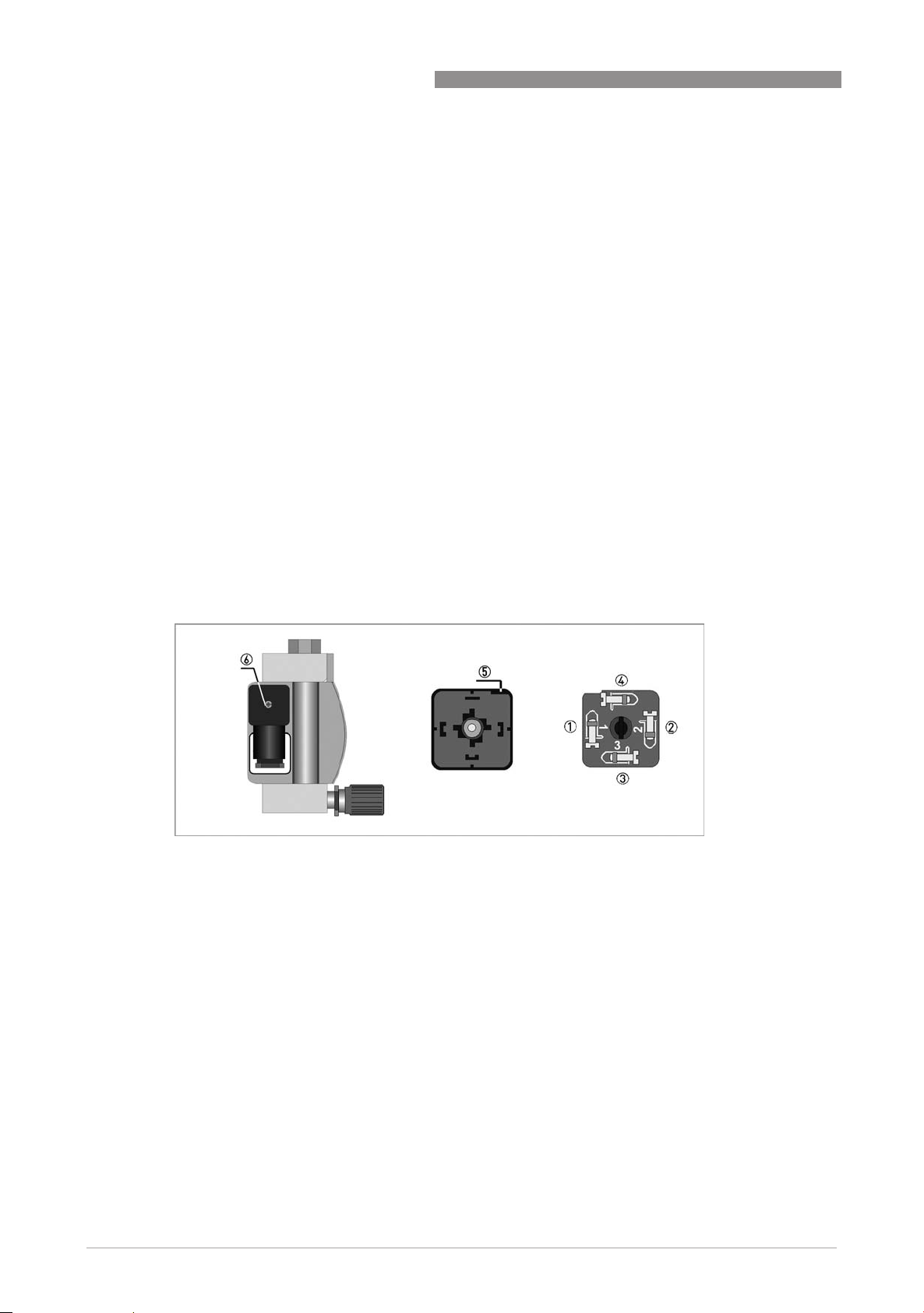
Connection diagrams
Contact connection Cable colors of assembled cable
1 Min minus white
2 Min plus yellow
3 Max minusMax minus green
4 Max plus brown
5 Lift slot
6 Fastening screw of connection box
10
www.krohne.com 03/2013 - 4002148602 AD DK32/34 II3G R03 en
Page 11

DK32 DK34
4.2 Earthing and equipotential bonding
If the device is not sufficiently electrostatically grounded via the process cables, an additional
earth connection must be established using the earth screw 1. The position of the ground
terminal is illustrated below. The connection guarantees only an electrostatic connection of the
device and does not comply with the requirements of an equipotential bonding connection.
DK32 - DK34
ELECTRICAL CONNECTIONS 4
www.krohne.com03/2013 - 4002148602 AD DK32/34 II3G R03 en
11
Page 12

5 OPERATION
5.1 Start-up
Start-up is only permitted when the variable area flowmeter:
• is correctly installed in the system and connected.
• has been checked for the proper state with regard to its installation and connection
requirements.
The user of the system must have it checked before start-up in compliance with the national
regulations for checks before startup.
5.2 Operation
Variable area flowmeters must be operated in such a way that they remain within the maximum
and minimum permissible temperatures and pressures and the electrical limit values.
Variable area flowmeters may only be operated if the equipment parts necessary for safety are
effective in the long run, and are not rendered inoperable during operation.
DK32 DK34
5.2.1 Operation as intrinsically safe equipment "ic"
Adjusting the limit switch during operation is permitted. To do so, remove the housing cover.
Replace the housing cover immediately after adjusting the limit switch.
5.2.2 Operation as non-sparking equipment "nA"
DANGER!
During operation it is only permitted to open the indicator if no explosive atmosphere is present.
12
www.krohne.com 03/2013 - 4002148602 AD DK32/34 II3G R03 en
Page 13
DK32 DK34
6.1 Maintenance
Maintenance work of a safety-relevant nature within the meaning of explosion protection may
only be carried out by the manufacturer, his authorised representative or under the supervision
of authorised inspectors.
For systems in hazardous areas, regular tests are required in order to maintain the proper
condition.
The following checks are recommended:
• Checking the housing, the cable entries and the feed lines for corrosion and/or damage.
• Checking the measuring unit and the piping connections for leakage.
The cover is to be closed following maintenance work on the display unit.
6.2 Dismantling
Replacing the display part
Due to the modular design of the variable area flowmeter, it is possible to replace a complete
display with an identical spare part in accordance with safety guidelines.
SERVICE 6
CAUTION!
There may be a loss of measuring accuracy!
Exchanging the entire device
Removal and installation are the responsibility of the operator.
Before disconnecting the electric connecting cable of the device, make sure that all cables
leading to the indication unit are isolated from the ground of the hazardous area. This also
applies to functional earthing conductors (FE) and equipotential bonding conductors (PA).
CAUTION!
•
Pressurized pipes have to be depressurized before removing the measuring unit.
•
In the case of environmentally critical or hazardous products, appropriate safety precautions
must be taken with regard to residual liquids in the measuring unit.
•
New gaskets have to be used when re-installing the device in the piping.
www.krohne.com03/2013 - 4002148602 AD DK32/34 II3G R03 en
13
Page 14

7 NOTES
DK32 DK34
14
www.krohne.com 03/2013 - 4002148602 AD DK32/34 II3G R03 en
Page 15

DK32 DK34
NOTES 7
www.krohne.com03/2013 - 4002148602 AD DK32/34 II3G R03 en
15
Page 16

KROHNE product overview
• Electromagnetic flowmeters
• Variable area flowmeters
• Ultrasonic flowmeters
• Mass flowmeters
• Vortex flowmeters
• Flow controllers
• Level meters
• Temperature meters
• Pressure meters
• Analysis products
• Products and systems for the oil & gas industry
• Measuring systems for the marine industry
Head Office KROHNE Messtechnik GmbH
Ludwig-Krohne-Str. 5
47058 Duisburg (Germany)
Tel.:+49 (0)203 301 0
Fax:+49 (0)203 301 10389
info@krohne.de
The current list of all KROHNE contacts and addresses can be found at:
© KROHNE 03/2013 - 4002148602 AD DK32/34 II3G R03 en - Subject to change without notice.
www.krohne.com
 Loading...