


VS-44UHDA
Table of contents
 Loading...
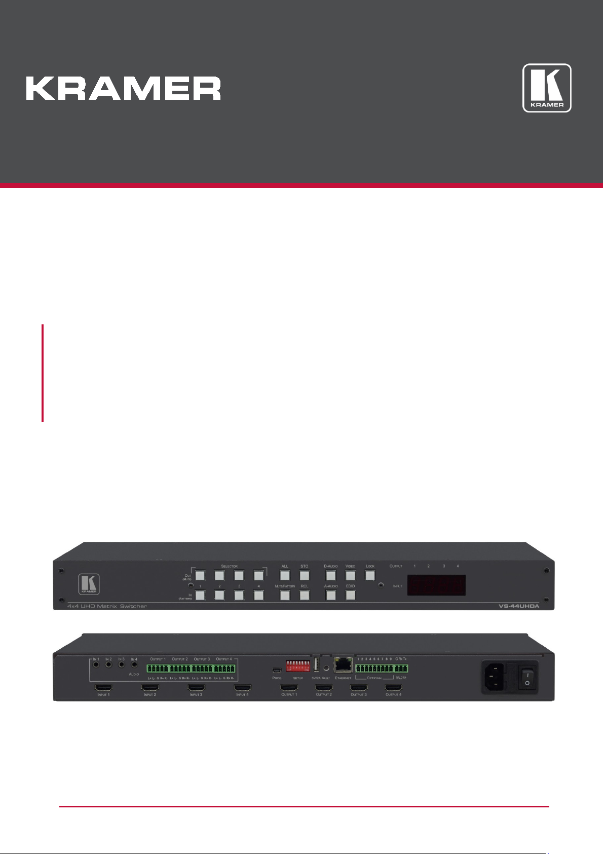
USER MANUAL
MODEL:
VS-44UHDA
4x4 UHD Matrix Switcher
P/N: 2900-300641 Rev 1 www.kramerAV.com

VS-44UHDA - Contents
i
Contents
Introduction 1
Getting Started 1
Overview 2
Typical Applications 3
Controlling your VS-44UHDA 3
Defining the VS-44UHDA 4x4 UHD Matrix Switcher 4
Installing in a Rack 6
Connecting the VS-44UHDA 7
Connecting Balanced/Unbalanced Stereo Audio Output 8
Connecting to VS-44UHDA via RS-232 8
Connecting VS-44UHDA via the ETHERNET Port 9
Operating VS-44UHDA via Front Panel Buttons 12
Routing the Signals 12
Storing and Recalling a Setup 23
Setting the Switching Mode 24
Setting the Switching Speed 25
Setting HDCP 25
Copying the EDID 26
Firmware Upgrade 27
Using the Embedded Web Pages 28
Switching and Setting the Ports 30
Changing Device Settings and Upgrading the Firmware 38
Managing Web Page Security 39
Setting the Timeout 42
Setting Switching Modes 43
Setting Step-in Devices 44
Managing the EDID 46
Viewing the About Us Page 52
Technical Specifications 53
Default Communication Parameters 53
Default Parameters 54
Protocol 3000 55
Understanding Protocol 3000 56
Kramer Protocol 3000 Syntax 57
Protocol 3000 Commands 58

Kramer Electronics Ltd.
VS-44UHDA - Introduction
1
Introduction
Welcome to Kramer Electronics! Since 1981, Kramer Electronics has been providing a world of
unique, creative, and affordable solutions to the vast range of problems that confront the video,
audio, presentation, and broadcasting professional on a daily basis. In recent years, we have
redesigned and upgraded most of our line, making the best even better!
Our 1,000-plus different models now appear in 14 groups that are clearly defined by function:
GROUP 1: Distribution Amplifiers; GROUP 2: Switchers and Routers; GROUP 3: Control
Systems; GROUP 4: Format/Standards Converters; GROUP 5: Range Extenders and
Repeaters; GROUP 6: Specialty AV Products; GROUP 7: Scan Converters and Scalers;
GROUP 8: Cables and Connectors; GROUP 9: Room Connectivity; GROUP 10: Accessories
and Rack Adapters; GROUP 11: Sierra Video Products; GROUP 12: Digital Signage; GROUP
13: Audio; and GROUP 14: Collaboration.
Getting Started
We recommend that you:
• Unpack the equipment carefully and save the original box and packaging materials for
possible future shipment.
• Review the contents of this user manual.
Go to www.kramerav.com/downloads/VS-44UHDA to check for up-to-date user manuals,
application programs, and to check if firmware upgrades are available (where appropriate).
Achieving the Best Performance
• Use only good quality connection cables (we recommend Kramer high-performance,
high-resolution cables) to avoid interference, deterioration in signal quality due to poor
matching, and elevated noise levels (often associated with low quality cables).
• Do not secure the cables in tight bundles or roll the slack into tight coils.
• Avoid interference from neighbouring electrical appliances that may adversely influence
signal quality.
• Position your Kramer VS-44UHDA away from moisture, excessive sunlight and dust.
This equipment is to be used only inside a building. It may only be connected to other
equipment that is installed inside a building.

Kramer Electronics Ltd.
VS-44UHDA - Introduction
2
Safety Instructions
Caution: There are no operator serviceable parts inside the unit.
Warning: Use only the power cord that is supplied with the unit.
Warning: Do not open the unit. High voltages can cause electrical shock! Servicing by
qualified personnel only.
Warning: Disconnect the power and unplug the unit from the wall before installing.
Recycling Kramer Products
The Waste Electrical and Electronic Equipment (WEEE) Directive 2002/96/EC aims to reduce
the amount of WEEE sent for disposal to landfill or incineration by requiring it to be collected
and recycled. To comply with the WEEE Directive, Kramer Electronics has made
arrangements with the European Advanced Recycling Network (EARN) and will cover any
costs of treatment, recycling and recovery of waste Kramer Electronics branded equipment on
arrival at the EARN facility. For details of Kramer’s recycling arrangements in your particular
country go to our recycling pages at www.kramerav.com/support/recycling
.
Overview
Congratulations on purchasing your Kramer VS-44UHDA.
VS-44UHDA is a high-quality 4x4 UHD Matrix Switcher for HDMI signals up to 4K@60Hz
4:2:0 and embedded/de-embedded analog audio. It reclocks and equalizes the signals and
can route any one of four HDMI, HDCP-compliant sources (selectable) to any or all outputs
simultaneously. The VS-44UHDA offers unmatched audio flexibility where any embedded
digital or analog audio input can be routed to any embedded digital or analog audio output in
addition to 4 ARC sources to produce an equivalent 12x12 audio matrix.
The VS-44UHDA provides exceptional quality, advanced and user-friendly operation, and
flexible control.
Exceptional Quality
• Max. data rate – 8.91Gbps data rate (2.97Gbps per graphics channel).
• Max. resolution – Up to 4K@60Hz UHD (4:2:0).
• Step-in over HDMI technology.
• HDMI, HDCP and DVI Compliance.
• HDMI support – Deep color, 3D, ARC, up to 7.1 uncompressed audio channels.
• Kramer reKlocking™ and equalization technology – rebuilds the digital signal to travel
longer distances.
Advanced and User-friendly Operation
• Fast switching.
• Audio level and balance support.

Kramer Electronics Ltd.
VS-44UHDA - Introduction
3
• Embedded pattern generator (480p) – With selectable patterns.
• Selectable HDCP per input.
• Memory locations – 8 presets for quick access to common configurations.
• Advanced EDID management per input.
• Active source and acceptor detection.
• Easy front-panel operation.
• Selectable switching speed.
• Lock button to prevent tampering.
• Kramer protocol 3000 support.
• Firmware upgrade via mini USB, Ethernet or the RS-232 port.
• Control Options – RS-232 serial commands transmitted by a PC, touch screen system or
other serial controller, Ethernet port via LAN.
• 7-segment display, indicating the video and audio status and other functions.
• Audio breakaway and AFV (audio-follow-video) operation support.
• Efficient power-saving features.
• Includes non-volatile memory that retains the last settings, after switching the power off
and then on again.
Flexible Connectivity
• Supports up to four analog audio inputs, four digital audio inputs and 4 ARC inputs.
• 4x4 switching for HDMI signals, 12x12 switching for audio signals.
• ARC from HDMI outputs and analog audio inputs to HDMI inputs 1 to 4.
• Supports Step-in function.
• Housed in a 19” 1U rack mountable enclosure, with rack ears included, and is fed from a
100-240 VAC universal switching power supply.
Typical Applications
The VS-44UHDA is ideal for the following typical applications:
• Presentation and multimedia applications.
• Systems that require automatic HDMI routing.
Controlling your VS-44UHDA
Control your VS-44UHDA directly via the front panel push buttons, or:
• By RS-232 serial commands transmitted by a touch screen system, PC, or other serial
controller.
• Via the Ethernet using built-in user-friendly Web pages.
Kramer Electronics Ltd.
VS-44UHDA - Defining the VS-44UHDA 4x4 UHD Matrix Switcher
4
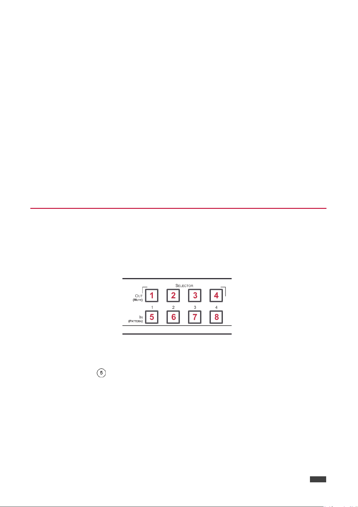
#
Feature
Function
IN (PATTERN)
Press to select the input (1 to 4) to switch after selecting an output (also
pattern in the Pattern mode).
OUT (MUTE) SELECTOR
Buttons
Press to select an output (1 to 4) to which the input is routed. Also used for
storing machine presets.
MUTE/PATTERN Button
Press to view the current pattern status and select the output/s to which a
D-AUDIO/A-AUDIO, and/or VIDEO buttons are pressed (lit).
ALL Button
Press to perform an action on all outputs (for example setting Mute mode,
input 2 to all the outputs.
STO and RCL Buttons
Press STO to store the current switching setting to a preset button.
Press RCL to recall the switching setting from a preset button.
A-AUDIO Button
Press to enable analog audio routing. When pressed together with VIDEO,
the analog audio is routed together with the video signal.
the digital audio is routed together with the video signal.
D-AUDIO/A-AUDIO, video is switched together with audio.
LOCK Button
Press and hold (for about 3 seconds) to toggle locking/releasing of the front
Switch mode.
EDID Button
Press to capture the EDID.
7-segment LED Display
input).
Defining the VS-44UHDA 4x4 UHD Matrix Switcher
This section defines the VS-44UHDA.
Figure 1: VS-44UHDA 4x4 UHD Matrix Switcher Front Panel
The behavior of the front panel buttons and the 7-segment display changes along with the operation
modes. For further details see Operating VS-44UHDA via Front Panel Buttons on page 12
.
SELECTOR Buttons
D-AUDIO Button
VIDEO Button
used for storing machine setups in the STO-RCL modes and for selecting a
pattern is routed.
Press to mute audio or video on a selected output when
Pattern mode and so on).
For switching, press ALL and then a specific INPUT button to route the
selected input to all outputs. For example, press ALL and then IN 2 to route
Press to enable digital audio routing. When pressed together with VIDEO,
Press to select video inputs. When pressed together with
panel buttons.
Press to save the following setups: HDCP (On/Off), ARC, Fast Switch and
OUTPUT/INPUT
Displays the selected inputs switched to the outputs (marked above each
VS-44UHDA - Defining the VS-44UHDA 4x4 UHD Matrix Switcher
5
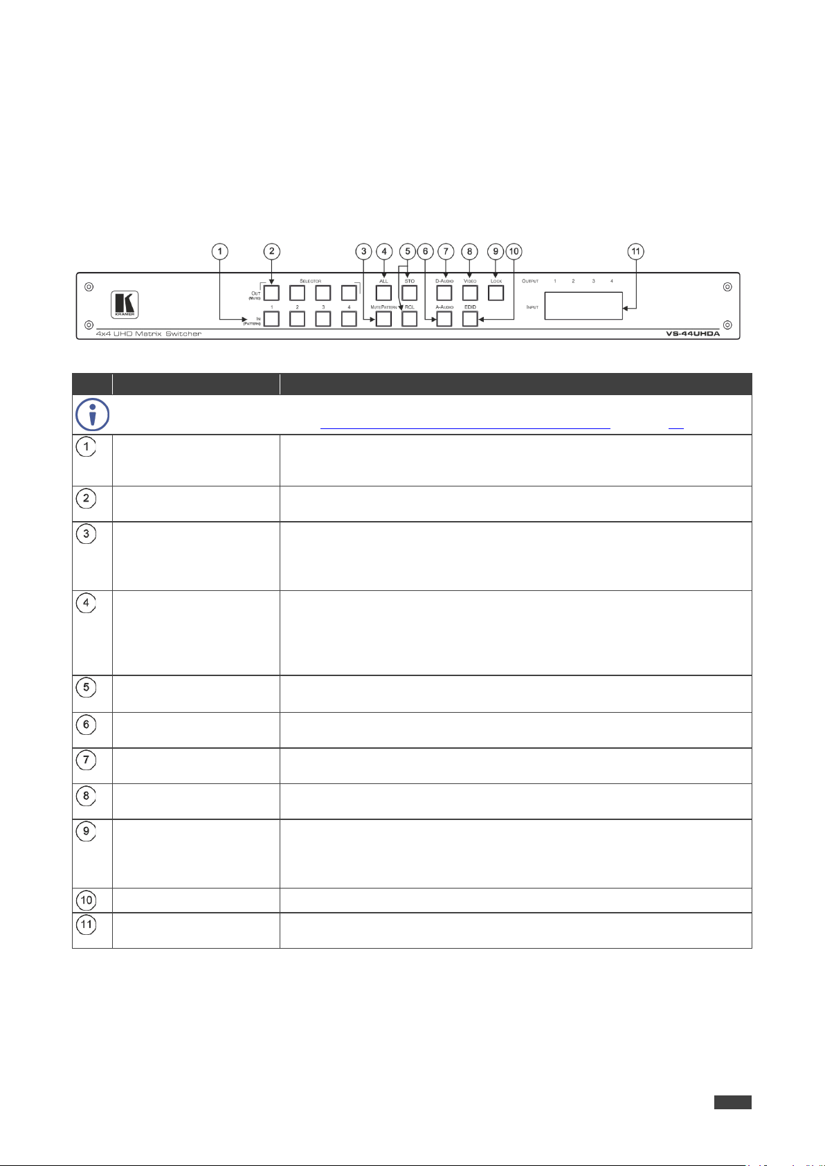
Connectors
INPUT HDMI Connector
Connect to the HDMI source (from 1 to 4).
AUDIO OUTPUT on 5-pin
Terminal Block Connectors
Connect to balanced stereo analog audio acceptor (see pinout below),
from 1 to 4.
OUTPUT HDMI Connectors
Connect to HDMI acceptors (from 1 to 4).
serial controller).
SETUP DIP-Switches
N/A 5V/2A USB Port
Use to charge a device.
Reset Button
Press and hold while powering the device to reset IP settings to factory
default values.
OPTIONAL Terminal Block
Connectors
N/A
RS-232 3-pin Terminal
Block Connectors
Connect to a PC or a serial controller.
Mains Power Connector
Connect to the mains power.
Mains Power Switch
Switch for turning the device on or off.
Figure 2: VS-44UHDA 4x4 UHD Matrix Switcher Rear Panel
# Feature Function
AUDIO IN on 3.5 Mini Jack
Connect to unbalanced stereo analog audio sources (from 1 to 4).
Kramer Electronics Ltd.
PROG Mini USB Port
Use for firmware upgrade or communication (connecting to a PC or a
ETHERNET RJ-45 Port Connect to your LAN.
Mains Power Fuse Fuse for protecting the device.
Kramer Electronics Ltd.
VS-44UHDA - Installing in a Rack
6
is earthed (grounded) and connected only to an electricity socket with
Installing in a Rack
This section provides instructions for rack mounting the VS-44UHDA. Before installing in a
rack, verify that the environment is within the recommended range:
• Operation temperature – 0° to 40°C (32 to 104°F).
• Storage temperature – -40° to +70°C (-40 to +158°F).
• Humidity – 10% to 90%, RHL non-condensing.
When installing on a 19" rack, avoid hazards by taking care that:
• It is located within recommended environmental conditions. Operating ambient
temperature of a closed or multi-unit rack assembly may exceed ambient room
temperature.
• Once rack mounted, there is enough air still flow around the VS-44UHDA.
• The VS-44UHDA is placed upright in the correct horizontal position.
• You do not overload the circuit(s). When connecting the VS-44UHDA to the supply
circuit, overloading the circuits may have a detrimental effect on overcurrent protection
and supply wiring. Refer to the appropriate nameplate ratings for information. For
example, for fuse replacement, see the value printed on the product label.
• The VS-44UHDA
grounding. Pay particular attention when electricity is supplied indirectly (for example,
when the power cord is not plugged directly into the wall socket but to an extension
cable or power strip). Use only the supplied power cord.
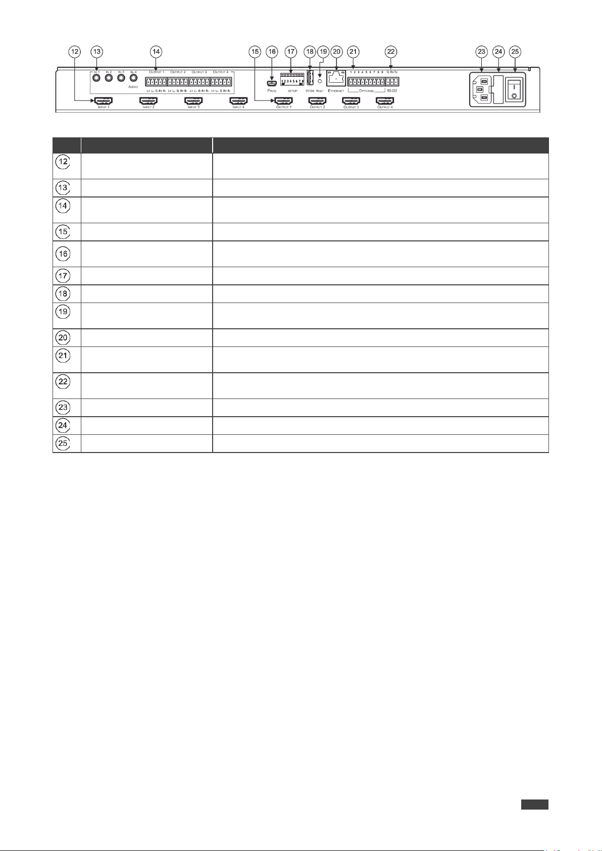
To rack-mount the VS-44UHDA:
1. Attach both ear brackets to the VS-44UHDA:
Remove the screws from each side of the
VS-44UHDA (3 on each side), and replace them
through the ear brackets.
2. Place the ears of the VS-44UHDA against the rack
rails and insert the appropriate screws (not provided)
through each of the four holes in the rack ears.
Some models, may feature built-in rack ears:
• Detachable rack ears can be removed for desktop use.
• Always mount the VS-44UHDA in the rack before connecting any cables or power.
• If you are using a Kramer rack adapter kit (for a machine that is not 19"), see the Rack
Adapters user manual for installation instructions available from our Web site
www.kramerav.com/downloads/VS-44UHDA
.

VS-44UHDA - Connecting the VS-44UHDA
7
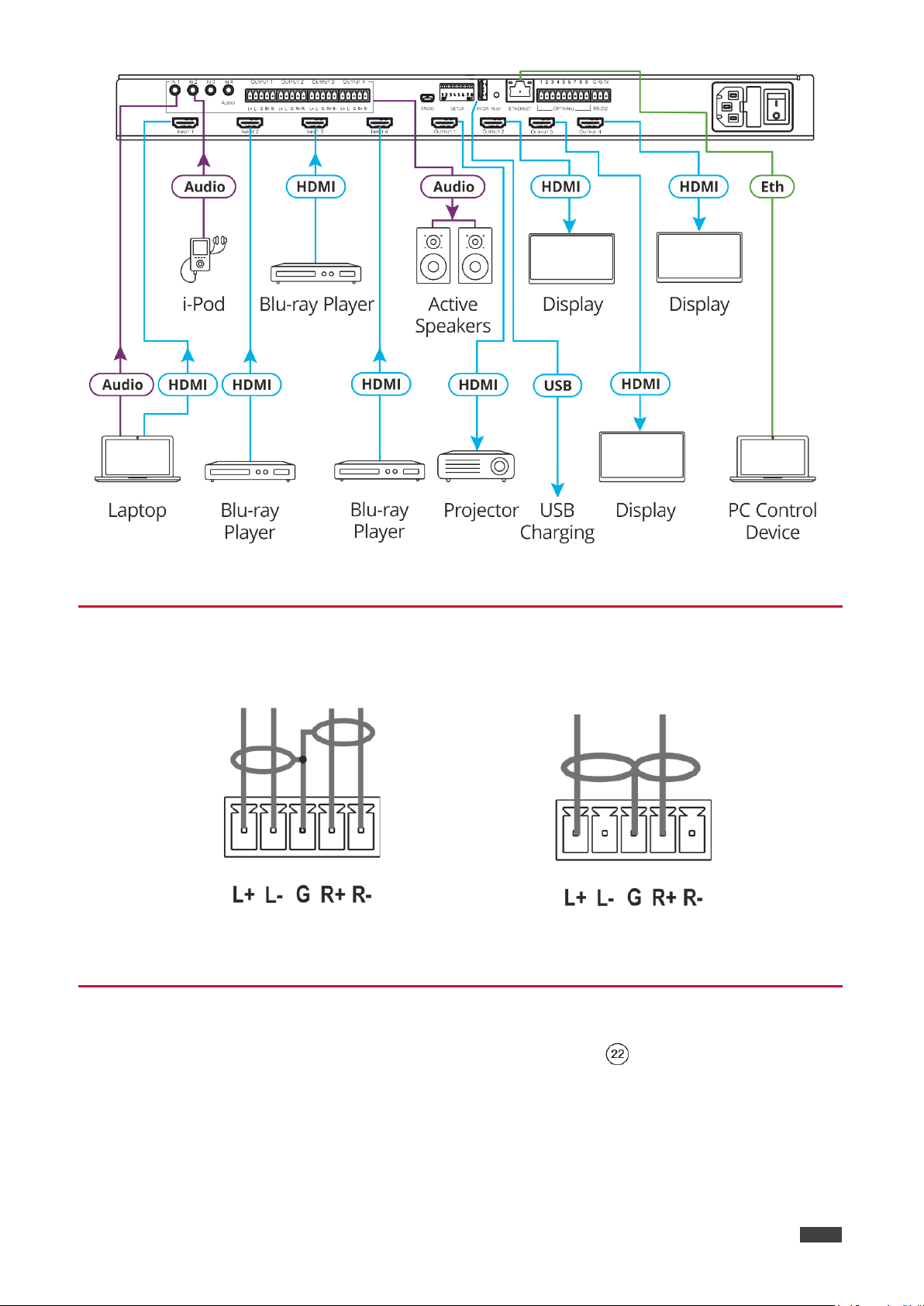
Connecting the VS-44UHDA
Always switch off the power to each device before connecting it to your VS-44UHDA. After
connecting your VS-44UHDA, connect its power and then switch on the power to each
device.
Although this connecting example shows only several inputs and outputs that are
connected, you can connect all the inputs and outputs simultaneously.
Kramer Electronics Ltd.
To connect the VS-44UHDA as illustrated in the example in Figure 3
, do the following:
1. Connect up to four video sources to the inputs (from INPUT 1 to INPUT 4). For example,
connect:
• A laptop to the INPUT 1 HDMI connector.
• Blu-ray players to the INPUT 2, 3 and 4 HDMI connectors.
2. Connect up to four analog stereo audio sources (from IN 1 to IN 4). For example,
connect:
• The analog audio output of a laptop to the AUDIO IN 1 3.5mm mini jack.
• An i-Pod to the AUDIO IN 2 3.5mm jack.
3. Connect the four video HDMI outputs (from OUTPUT 1 to OUTPUT 4) to up to four
acceptors. For example, connect the:
• OUTPUT 1 HDMI connector to a projector.
• OUTPUT 2, OUTPUT 3 and OUTPUT 4 HDMI connectors each to a display.
4. Connect the four balanced analog output 5-pin terminal block connectors (from OUTPUT
1 to OUTPUT 4) to up to four audio acceptors. For example, connect OUTPUT 4 to
active speakers.
5. Connect the power cord.
We recommend that you use only the power cord that is supplied with this machine
6. If required, connect:
• The 5V/2A USB port to the USB port of another device to charge it.
• The ETHERNET port.
Kramer Electronics Ltd.
VS-44UHDA - Connecting the VS-44UHDA
8
Figure 3: Connecting to the VS-44UHDA Rear Panel
Connecting Balanced/Unbalanced Stereo Audio Output
The following are the pinouts for connecting to balanced or unbalanced stereo audio sources:
Figure 4: Connecting to a Balanced
Stereo Audio Output
Figure 5: Connecting an Unbalanced Stereo
Audio Acceptor to the Balanced Output
Connecting to VS-44UHDA via RS-232
You can connect to the VS-44UHDA via an RS-232 connection using, for example, a PC.
To connect to the VS-44UHDA via RS-232:
• Connect the RS-232 rear panel port on the VS-44UHDA unit via a
9-wire straight cable (only pin 2 to pin 2, pin 3 to pin 3, and pin 5 to pin 5 need to be
connected) to the RS-232 9-pin D-sub port on your PC.
Kramer Electronics Ltd.
VS-44UHDA - Connecting the VS-44UHDA
9
Connecting VS-44UHDA via the ETHERNET Port
You can connect to the VS-44UHDA via Ethernet using either of the following methods:
• Directly to the PC using a crossover cable (see
Connecting the Ethernet Port Directly to a
PC on page 9).
• Via a network hub, switch, or router, using a straight-through cable (see Connecting the
Ethernet Port via a Network Hub or Switch on page 11).
If you want to connect via a router and your IT system is based on IPv6, speak to your IT
department for specific installation instructions
Connecting the Ethernet Port Directly to a PC
You can connect the Ethernet port of the VS-44UHDA directly to the Ethernet port on your PC
using a crossover cable with RJ-45 connectors.
This type of connection is recommended for identifying the VS-44UHDA
with the factory configured default IP address.
After connecting the VS-44UHDA to the Ethernet port, configure your PC as follows:
1. Click Start > Control Panel > Network and Sharing Center.
2. Click Change Adapter Settings.
3. Highlight the network adapter you want to use to connect to the device and click Change
settings of this connection.
The Local Area Connection Properties window for the selected network adapter appears
as shown in Figure 6
.
4. Highlight either Internet Protocol Version 6 (TCP/IPv6) or Internet Protocol Version 4
(TCP/IPv4) depending on the requirements of your IT system.
Figure 6: Local Area Connection Properties Window
VS-44UHDA - Connecting the VS-44UHDA
10
5. Click Properties.
The Internet Protocol Properties window relevant to your IT system appears as shown in
Figure 7 or Figure 8
Kramer Electronics Ltd.
.
Figure 7: Internet Protocol Version 4 Properties Window
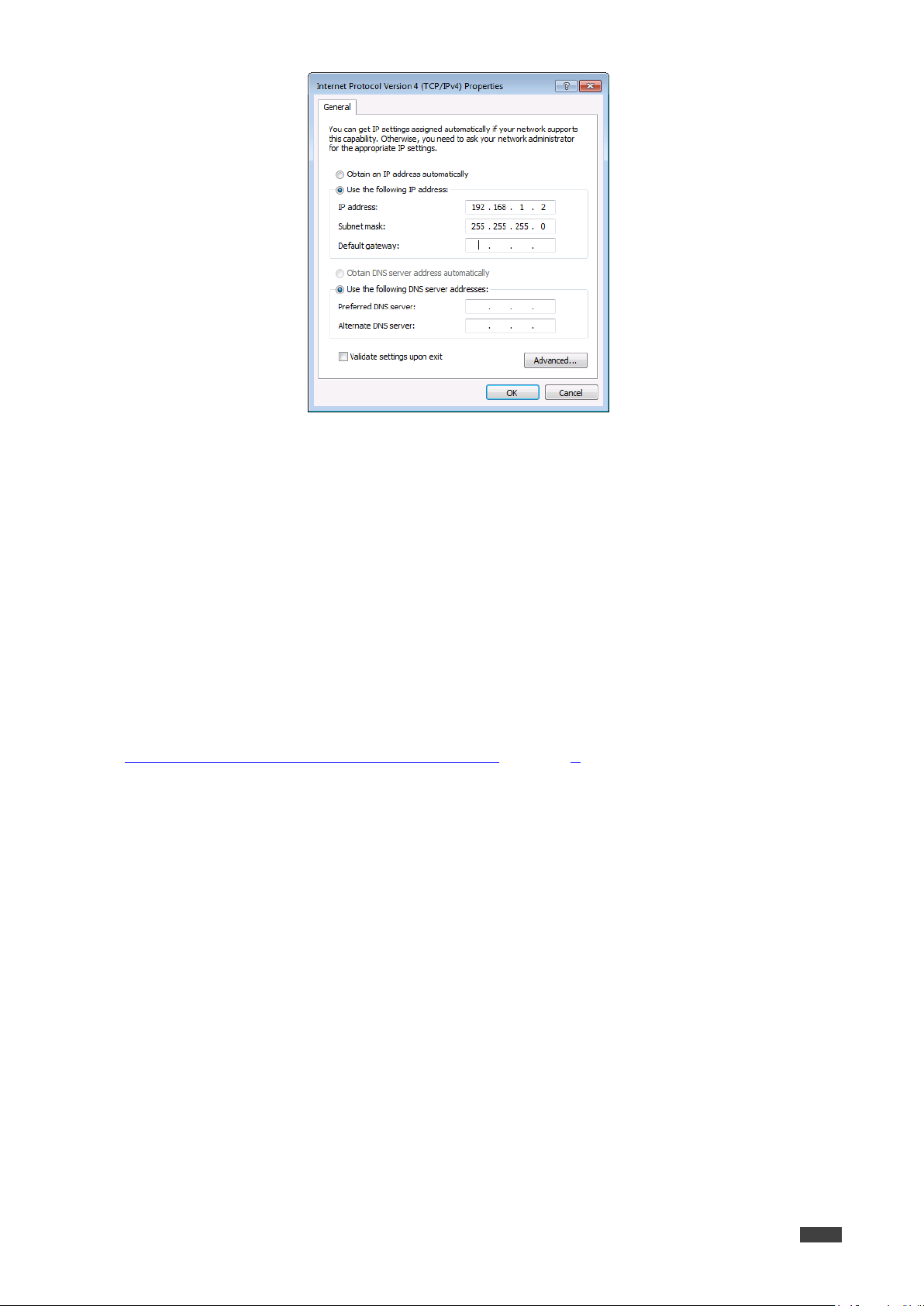
6. Select Use the following IP Address for static IP addressing and fill in the details as
shown in Figure 9
For TCP/IPv4 you can use any IP address in the range 192.168.1.1 to 192.168.1.255
(excluding 192.168.1.39) that is provided by your IT department.
Figure 8: Internet Protocol Version 6 Properties Window
.
VS-44UHDA - Connecting the VS-44UHDA
11
7. Click OK.
Kramer Electronics Ltd.
Figure 9: Internet Protocol Properties Window
8. Click Close.
Connecting the Ethernet Port via a Network Hub or Switch
You can connect the Ethernet port of the VS-44UHDA to the Ethernet port on a network hub or
using a straight-through cable with RJ-45 connectors.
Control Configuration via the Ethernet Port
To control several units via Ethernet, connect the Master unit (Device 1) via the Ethernet port
to the Ethernet port of your PC. Use your PC provide initial configuration of the settings (see
Connecting VS-44UHDA via the ETHERNET Port on page 9
).

Kramer Electronics Ltd.
VS-44UHDA - Operating VS-44UHDA via Front Panel Buttons
12
Operating VS-44UHDA via Front Panel Buttons
Press the power switch to power the device. During the 10-second initialization process,
the:
• 7-segment display LEDs are on.
• All the front panel buttons illuminate.
• The FPGA/EPLD version (P), the firmware version (F) and the build version (b) appear in
succession.
Following initialization, the front panel buttons and 7-segment display enter normal operation:
• The 7-segment display shows the video IN-OUT status.
• The current operation mode button illuminates (VIDEO, by default).
• An illuminated IN (PATTERN) button indicates an active signal connected to the input.
• An illuminated OUT (MUTE) button indicates that an acceptor is connected to the output.
The VS-44UHDA front panel buttons enable performing the following functions:
• Routing the Signals, on page 12
• Storing and Recalling a Setup, on page 23.
• Setting the Switching Mode, on page 24.
• Setting the Switching Speed, on page 25.
• Setting HDCP, on page 25.
• Copying the EDID, on page 26.
.
Routing the Signals
You can switch the video and the audio signals together (AFV) or switch them separately, via
the following switching modes:
• Switching the Video Signal, on page 13
• Routing an Analog Audio Input to HDMI and Analog Audio Outputs, on page 14.
• Routing a Digital Audio Input to HDMI and Analog Outputs, on page 15.
• Switching the Video and the Audio Signal Simultaneously, on page 16.
• Muting/Unmuting an Output, on page 17.
• Routing a Pattern to the Output, on page 18.
• Operating in ARC Mode, on page 19.
.
VS-44UHDA - Operating VS-44UHDA via Front Panel Buttons
13
Switching the Video Signal
The VIDEO button on the VS-44UHDA front panel enables video routing.
To switch a video input to an output:
1. Press VIDEO .
The button illuminates and the 7-segment display shows the current IN-OUT video
status.
On the front panel buttons:
• An illuminated input button means that an active signal is detected on that input.
• An illuminated output button means that a display is connected to that output.
• A flashing output button means that a non-HDCP display is connected to that output.
Note that in the case that an HDCP-encrypted input is routed through the matrix to a
non-HDCP screen, the video will not be presented and the non-HDCP screen will turn
black.
Kramer Electronics Ltd.
On the 7-segment display:
• A digit (from 1 to 4) shows the input number that is currently routed to the output.
• “P” under an output number indicates that a pattern is routed to that output.
• “0” under an output number indicates that the output is muted.
2. Press an OUT (MUTE) button (1 to 4).
The 7-segment display LED, under the selected output, flashes.
Press ALL (instead of an output button) to route the selected input to all the outputs. All
the 7-segment display LEDs flash.
3. Press an IN (PATTERN) button (1 to 4).
The selected input is switched to the selected output (or to all the outputs if ALL was
pressed instead) and the 7-segment display shows the current status.
Kramer Electronics Ltd.
VS-44UHDA - Operating VS-44UHDA via Front Panel Buttons
14
Routing an Analog Audio Input to HDMI and Analog Audio Outputs
The A-AUDIO button on the VS-44UHDA front panel enables to route the analog audio
input signals to the balanced stereo analog audio outputs and the HDMI outputs .
The analog audio input can be routed separately to either HDMI or analog outputs only via
the embedded web pages see Switching Audio in Breakaway Mode on page 36
Generally, analog routing is enabled by pressing A-AUDIO:
• When it is illuminated, the analog audio input is the audio source.
To switch an analog audio input signal to HDMI and analog outputs:
1. Press A-AUDIO .
The button illuminates (analog audio input to HDMI and balanced audio output mode)
and the 7-segment display shows the current IN-OUT analog audio status.
On the front panel buttons:
• An illuminated input button means that an active signal is detected on that input.
.
• An illuminated output button means that a display that supports audio is detected on
that output.
• A dark button means either that the display that is connected does not support audio
or that a display is not connected at all.
On the 7-segment display:
• “d” under an output number indicates that an HDMI audio input is the current audio
source.
• “C” under an output number indicates that ARC audio is routed to that output.
• “0” under an output number indicates that the analog audio output is muted.
• “.” under an output number indicates that the HDMI output port is in ARC mode.
• Any digit shows the analog audio input switching state.
2. While A-AUDIO is on, select an output button (for example, 4) and then an input button
(for example, 2). Analog audio input 2 is routed to balanced stereo audio output 4 and on
the 7-segment display, INPUT 2 appears under OUTPUT 4.
When switching you can also press:
• An output button (1 to 4) and then OUT (MUTE) to mute the selected output (turns 0).
• ALL (instead of an output button) and then an input button to route the selected input
to all the outputs.
All the 7-segment display LEDs flash and then display the selected input.
Kramer Electronics Ltd.
VS-44UHDA - Operating VS-44UHDA via Front Panel Buttons
15
illuminated input button means that an active digital audio signal is detected on that
Routing a Digital Audio Input to HDMI and Analog Outputs
The D-AUDIO button on the VS-44UHDA front panel enables to route the HDMI embedded
audio input signals to the balanced stereo audio outputs and the HDMI outputs .
Generally, digital routing is enabled by pressing D-AUDIO:
• When this button is illuminated, the HDMI input embedded audio is the audio source.
To switch an HDMI audio input to digital and analog outputs:
1. Press D-AUDIO .
The button illuminates (HDMI audio input to HDMI and analog output mode) and the
7-segment display shows the current IN-OUT digital audio status.
On the front panel buttons:
• An
input that supports LPCM audio.
• A dark input button means that there is no active digital audio source on that input (or
that the source is DVI).
• A flashing input button means that a Dolby digital audio, Dolby-TrueHD audio, or AC-3
audio signal from a DVD -player is detected on that input.
• An illuminated output button means that a display that supports LPCM audio is
connected to that output.
• A dark button means either that the display that is connected does not support audio
or that a display is not connected at all.
• A flashing output button means that a display is connected that does not support
LPCM.
On the 7-segment display:
• “A” under an output number indicates that an analog audio signal is currently routed
to that output.
• “0” under an output number indicates that the audio output is muted.
• “.” under an output number indicates that the HDMI output port is in ARC mode.
• Any digit shows the HDMI audio input switching state.
2. While D-AUDIO is on, select an output button (for example, 3) and then an input button
(for example, 1). HDMI audio input 1 is routed to HDMI audio output 3 and the balanced
stereo audio output 3, and on the 7-segment display, INPUT 1 appears under OUTPUT
3.
When switching you can also press:
• An output button (1 to 4) and then OUT (MUTE) to mute the selected output (turns 0).
• ALL (instead of an output button) and then an input button to route the selected input
to all the outputs.
All the 7-segment display LEDs flash and then display the selected input.
Kramer Electronics Ltd.
VS-44UHDA - Operating VS-44UHDA via Front Panel Buttons
16
Switching the Video and the Audio Signal Simultaneously
You can select the analog or the digital audio signal to switch to the output together with the
video signal.
To switch the digital audio and video signals together to an output:
1. Press D-AUDIO and VIDEO simultaneously.
The buttons illuminate and the 7-segment display shows the current IN-OUT video
status.
2. Press an OUT (MUTE) button (1 to 4).
The 7-segment display LED, under the selected output, flashes.
Press ALL (instead of an output button) to route the selected input to all the outputs. All
the 7-segment display LEDs flash.
3. Press an IN (PATTERN) button (1 to 4).
The selected audio input is switched to the selected output (or to all the outputs if ALL
was pressed instead) and the 7-segment display shows the current status.
To switch the analog audio and video signals together to an output:
1. Press A-AUDIO and VIDEO simultaneously.
The buttons illuminate and the 7-segment display shows the current IN-OUT video
status.
2. Press an OUT (MUTE) button (1 to 4).
The 7-segment display LED, under the selected output, flashes.
Press ALL (instead of an output button) to route the selected input to all the outputs. All
the 7-segment display LEDs flash.
3. Press an IN (PATTERN) button (1 to 4).
The selected audio input is switched to the selected output (or to all the outputs if ALL
was pressed instead) and the 7-segment display shows the current status.
VS-44UHDA - Operating VS-44UHDA via Front Panel Buttons
17
Muting/Unmuting an Output
You can mute/unmute an audio signal and a video signal separately.
To mute/unmute an audio signal:
1. Press A-AUDIO or D-AUDIO.
The buttons illuminate.
2. Press an OUT (MUTE) button (1 to 4).
Press ALL (instead of an output button) to mute/unmute all the outputs. All the
7-segment display LEDs flash.
3. Press MUTE/PATTERN to mute/unmute the output.
The muted output appears as “0” on the 7-segment display.
To mute/unmute a video signal:
1. Press VIDEO.
The button illuminates and the 7-segment display shows the current IN-OUT video
status.
Kramer Electronics Ltd.
2. Press an OUT (MUTE) button (1 to 4).
The 7-segment display LED, under the selected output, flashes.
Press ALL (instead of an output button) to mute/unmute all the outputs. All the
7-segment display LEDs flash.
3. Press MUTE/PATTERN to mute/unmute the output.
The muted output appears as “0” on the 7-segment display.
Kramer Electronics Ltd.
VS-44UHDA - Operating VS-44UHDA via Front Panel Buttons
18
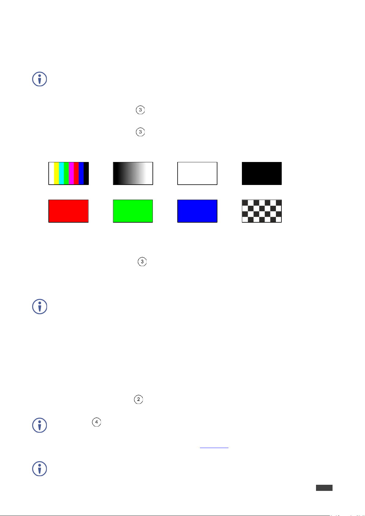
1 (Color Bars)
2 (Ramp)
3 (Solid White)
4 (Solid Black)
5 (Solid Red)
6 (Solid Green)
7 (Solid Blue)
8 (Checkboard)
Routing a Pattern to the Output
VS-44UHDA generates 8 embedded patterns. These patterns can be routed at a resolution of
480p to any of the outputs.
Once a pattern is selected, that same pattern is routed to all the selected outputs.
A pattern is selected by pressing inputs 1 to 4 when in the Pattern mode as follows:
• When MUTE/PATTERN is illuminated, press IN1 for pattern 1, IN 2 for pattern 2, IN 3
for pattern 3 and IN 4 for pattern 4.
• When MUTE/PATTERN flashes, press IN1 for pattern 5, IN 2 for pattern 6, IN 3 for
pattern 7 and IN 4 for pattern 8.
Figure 10: VS-44UHDA Embedded Patterns
To route a pattern:
1. Press MUTE/PATTERN :
• Once: button illuminates, press IN 1 to IN 4 to select patterns 1 to 4.
• Twice: button flashes, press IN 1 to IN 4 to select patterns 5 to 8.
On the front panel buttons:
• An illuminated output button means that a display is connected on that output.
• An illuminated input button indicates the current pattern selected.
On the 7-segment display:
• “P” under an output number indicates that a pattern is routed to that output.
• “-” under an output number indicates that a video input is routed to that output.
• “0” under an output number indicates that the output is muted.
2. Press an OUT (MUTE) button (1 to 4).
The 7-segment display LED, under the selected output, flashes.
Press ALL (instead of an output button) to route a pattern to all the outputs. All the
7-segment display LEDs flash.
3. Press an input button to select a pattern (see Figure 10
The 7-segment display shows the new pattern status.
Press VIDEO, D-AUDIO or A-AUDIO to exit pattern mode.
).
Kramer Electronics Ltd.
VS-44UHDA - Operating VS-44UHDA via Front Panel Buttons
19
Operating in ARC Mode
ARC (Audio Return Channel) can be set via the front panel buttons or the embedded
webpages (see Switching Audio in Breakaway Mode on page 36 and Setting Input Parameters
on page 32).
VS-44UHDA features three types of audio return channels (ARC):
• Routing HDMI Audio Output Signals to the Balanced Audio Outputs on page 19
.
• Routing HDMI Audio Output Signals to HDMI Input Ports on page 20.
• Routing Analog Audio Inputs to HDMI Input Ports on page 22.
Routing HDMI Audio Output Signals to the Balanced Audio Outputs
To route an HDMI audio output to a balanced stereo audio output, enable ARC on the HDMI
output ports and then route them.
To set an HDMI output to ARC mode:
ARC can be enabled or disabled at any time, regardless of whether a display is connected
to the HDMI output or not.
1. Press and hold MUTE/PATTERN and ALL simultaneously until both buttons illuminate
and the device enters ARC mode:
On the front panel button:
• A flashing output button means that the audio of that output is set to ARC mode.
• An illuminated Output button means that the output is not in ARC mode.
2. Press one or more output buttons:
• If the selected button flashes, that output to set to ARC mode.
• If the selected button stops flashing, ARC mode is disabled for that output.
The LOCK button flashes.
3. Press LOCK to save changes.
The LOCK button flashes until the changes are saved. The device exits the ARC mode
and returns to Video switching mode.
The ARC can be routed to any of the balanced audio outputs (and to the inputs).

VS-44UHDA - Operating VS-44UHDA via Front Panel Buttons
20
To route an HDMI OUT ARC to a balanced stereo audio output port:
1. Press D-AUDIO and A-AUDIO simultaneously.
Both buttons illuminate and the device enters the ARC routing mode (for example, HDMI
OUT 1, 2, 3 and 4 are enabled).
On the front panel button:
• An illuminated output button means that the corresponding output port is ARC
enabled.
• A dark output button means that the corresponding output port is not ARC enabled.
On the 7-segment display:
• “.” under an output number indicates that arc is enabled on the corresponding output
(outputs 1 to 4 in this example).
• “A” under an output number indicates that an analog audio input is routed to that
output.
• “d” under an output number indicates that the embedded audio is routed to that output.
Kramer Electronics Ltd.
• “0” under an output number indicates that the audio output is muted.
2. Press an ARC enabled output button (for example OUT 3). The corresponding
7-segment display LED flashes.
3. Press an output button (for example OUT 2) to select the balanced audio output routing
destination.
The flashing 7-segment display LED shows the selected output number and
ARC (for example, OUT 3) is routed to the selected balanced audio output (for example,
OUT 2).
Routing HDMI Audio Output Signals to HDMI Input Ports
To route an HDMI audio output to HDMI input ports, enable ARC on the HDMI output ports
and then route them.
To set an HDMI output to ARC mode:
ARC can be enabled or disabled at any time, regardless of whether a display is connected
to the HDMI output or not.
1. Press and hold MUTE/PATTERN and ALL simultaneously until both buttons illuminate
and the device enters ARC mode:
On the front panel button:
• A flashing output button means that the audio of that output is set to ARC mode.
• An illuminated Output button means that the output is not in ARC mode.

VS-44UHDA - Operating VS-44UHDA via Front Panel Buttons
21
2. Press one or more output buttons:
• If the selected button flashes, that output to set to ARC mode.
• If the selected button stops flashing, ARC mode is disabled for that output.
The LOCK button flashes.
3. Press LOCK to save changes.
The LOCK button flashes until the changes are saved. The device exits the ARC mode
and returns to Video switching mode.
The ARC can be routed to the inputs and to any of the balanced audio outputs.
To route an HDMI OUT ARC to an HDMI input port:
1. Press D-AUDIO and A-AUDIO simultaneously.
Both buttons illuminate and the device enters the ARC routing mode (for example, HDMI
OUT 1, 2, 3 and 4 are enabled).
Kramer Electronics Ltd.
2. Press D-AUDIO until it flashes.
The out HDMI Arc-enabled outputs illuminate, as before.
The ARC-enabled inputs flash (for example, 1, 2 and 4 are ARC enabled, 3 is illuminated
therefore not enabled).
On the front panel button:
• An illuminated output button means that the corresponding output port is ARC
enabled.
• A dark output button means that the corresponding output port is not ARC enabled.
• An illuminated input button means that it is a disabled ARC input.
• A flashing input button means that it is ARC-enabled.
On the 7-segment display:
• “.” under an output number indicates that arc is enabled on the corresponding output
(outputs 1 to 4 in this example).
• “A” under an output number indicates that an analog audio input is routed to that
output.
• “d” under an output number indicates that the embedded audio is routed to that output.
• “0” under an output number indicates that the audio output is muted.
3. Press an ARC enabled input button (for example, IN 2) to select the destination port.
The corresponding 7-segment display LED flashes.
4. Press an output button (for example OUT 4) to select the HDMI audio output that will be
routed to the input.
The flashing 7-segment display LED shows the selected input number and
after selecting the HDMI audio OUT the port number appears (4).
HDMI OUT 4 audio signal is routed to ARC input 2.
Kramer Electronics Ltd.
VS-44UHDA - Operating VS-44UHDA via Front Panel Buttons
22
Routing Analog Audio Inputs to HDMI Input Ports
To route an analog audio input to an HDMI input, enable ARC on the HDMI input ports and
then route them.
To set an HDMI input to ARC mode:
ARC can be enabled or disabled at any time, regardless of whether an amplifier is
connected to the HDMI input or not.
Inputs can be set either to the Step-in mode or the ARC mode.
1. Press and hold EDID and ALL simultaneously until both buttons illuminate and the
device enters ARC mode:
On the front panel button:
• A flashing input button means that it is set to ARC mode.
• An illuminated input button means that it is set to Step-in mode.
2. Press one or more output buttons:
• If the selected button flashes, that input to set to ARC mode.
• If the selected button stops flashing, ARC mode is disabled for that input.
The LOCK button flashes.
3. Press LOCK to save changes.
The LOCK button flashes until the changes are saved. The device exits the ARC mode
and returns to Video switching mode.
The analog inputs can be routed to inputs 1 to 4.
To route an analog audio input to an HDMI input port:
1. Press D-AUDIO and A-AUDIO simultaneously.
Both buttons illuminate and the device enters the ARC routing mode (for example, HDMI
OUT 1, 2, 3 and 4 are enabled).
2. Press A-AUDIO until it flashes.
The out HDMI Arc-enabled outputs illuminate, as before.
The ARC-enabled inputs flash (for example, 1, 2 and 4 are ARC enabled, 3 is illuminated
therefore not enabled).
On the front panel button:
• An illuminated output button means that the corresponding output port is ARC
enabled.
• A dark output button means that the corresponding output port is not ARC enabled.
• An illuminated input button means that it is a disabled ARC input.
• A flashing input button means that it is ARC-enabled.
Kramer Electronics Ltd.
VS-44UHDA - Operating VS-44UHDA via Front Panel Buttons
23
On the 7-segment display:
• “.” under an output number indicates that arc is enabled on the corresponding output
(outputs 1 to 4 in this example).
• “A” under an output number indicates that an analog audio input is routed to that
output.
• “d” under an output number indicates that the embedded audio is routed to that output.
• “0” under an output number indicates that the audio output is muted.
3. Press an ARC enabled input button (for example IN 1) to select the input destination
port.
The corresponding 7-segment display LED flashes.
4. Press an input button (for example IN 2) to select the analog audio input that will be
routed to the input destination port.
The flashing 7-segment display LED shows the selected input number and
after selecting the HDMI audio IN the port number appears (2).
Analog audio input 2 is routed to ARC input 1.
Storing and Recalling a Setup
VS-44UHDA can store up to 8 setups. Each setup includes the video and audio current
switching state, the output audio volume and balance, the EDID, the ARC/audio mode, and the
switch mode and speed.
In Store-Recall mode, OUT 1 corresponds to setup 1, IN 1 corresponds to setup 5, and so on.
Figure 11: VS-44UHDA 4x4 UHD Matrix Switcher Front Panel
To store a setup:
1. Press STO .
The STO button illuminates.
2. Press an IN or an OUT button (from 1 to 4).
For example, when pressing IN 4, the current device state is stored to setup 8.
3. Press STO.
The current device state is stored to setup 8 and the STO button no longer illuminates.
VS-44UHDA - Operating VS-44UHDA via Front Panel Buttons
24
To recall a setup:
1. Press RCL .
The RCL button illuminates.
2. Press an IN or OUT button to recall the setup stored in that IN/OUT.
The selected button flashes.
If a setup is stored in the selected setup button, the corresponding 7-segment display LED
flashes. If nothing is stored the 7-segment LED is on.
3. Press RCL.
The recalled setup is applied and the RCL button no longer illuminates.
You need to press RCL within 10 seconds, to apply settings.
Setting the Switching Mode
Set the following switching modes separately for each output:
Kramer Electronics Ltd.
• Manual mode (IN 1): inputs are switched to outputs via the front panel buttons.
• Priority mode (IN 2): the VS-44UHDA switches the source with the highest priority to the
output.
• Last connected mode (IN 3): the last detected active source is switched to the output.
To select the switching mode:
1. Press RCL and MUTE/PATTERN simultaneously. Both buttons illuminate.
2. Press an output button (or press ALL).
The corresponding 7-segment display LEDs flash and LOCK button flashes.
3. Press IN 1, IN 2 or IN 3.
4. Press LOCK to save the settings to that output and exit Switching mode.
Loading...