


 Loading...
USER MANUAL
MODEL:
VS-42UHD
4x2 HDMI Matrix Switcher
P/N: 2900-300609 Rev 4 |
www.kramerAV.com |


Contents
1 |
Introduction |
1 |
2 |
Getting Started |
2 |
2.1 |
Achieving the Best Performance |
2 |
2.2 |
Safety Instructions DC |
2 |
2.3 |
Recycling Kramer Products |
3 |
3 |
Overview |
4 |
3.1 |
Using the IR Transmitter |
5 |
3.2 |
Defining the VS-42UHD 4x2 HDMI Matrix Switcher |
6 |
4 |
Connecting the VS-42UHD |
8 |
4.1 |
Connecting a Serial Controller via RS-232 |
9 |
4.2 |
Connecting to the VS-42UHD via Ethernet |
9 |
4.3 |
Connecting the Remote Contact-Closure Switches |
12 |
5 |
Principles of Operation |
14 |
5.1 |
Automatic Signal Detection |
14 |
5.2 |
Input Switching Modes |
14 |
5.3 |
EDID Operation |
15 |
5.4 |
Step-in Functionality |
15 |
6 |
Operating the VS-42UHD 4x2 HDMI Matrix Switcher |
16 |
6.1 |
Switching an Input to an Output |
16 |
6.2 |
Acquiring an EDID from an Output |
16 |
6.3 |
Muting and Unmuting the Outputs |
17 |
6.4 |
Locking and Unlocking the Front Panel Buttons |
18 |
6.5 |
Generating a Test Pattern |
18 |
7 |
Configuring and Maintaining the VS-42UHD |
19 |
7.1 |
Setting the DIP-Switches |
19 |
7.2 |
Resetting the VS-42UHD to Factory Default Settings |
20 |
7.3 |
Upgrading the Firmware |
20 |
8 |
Operating the VS-42UHD Remotely via the Web Pages |
21 |
8.1 |
Browsing the VS-42UHD Web Pages |
21 |
8.2 |
Routing Page |
23 |
8.3 |
EDID Page |
27 |
8.4 |
Device Setting Page |
29 |
8.5 |
Firmware Upgrade Page |
30 |
8.6 |
About Us Page |
31 |
9 |
Wiring the Twisted Pair RJ-45 Connectors |
32 |
10 |
Technical Specifications |
33 |
11 |
Default Communication Parameters |
34 |
12 |
Default EDID |
35 |
13 |
Protocol 3000 |
37 |
13.1 |
Understanding Protocol 3000 |
38 |
13.2 |
Kramer Protocol 3000 Syntax |
40 |
13.3 |
Protocol 3000 Commands |
41 |
VS-42UHD – Contents |
i |
Figures
Figure 1: VS-42UHD 4x2 HDMI Matrix Switcher Front |
6 |
Figure 2: VS-42UHD 4x2 HDMI Matrix Switcher Rear |
7 |
Figure 3: Connecting the VS-42UHD 4x2 HDMI Matrix Switcher |
9 |
Figure 4: Local Area Connection Properties Window |
10 |
Figure 5: Internet Protocol Version 4 Properties Window |
11 |
Figure 6: Internet Protocol Properties Window |
12 |
Figure 7: Remote Contact-closure Switch Connections |
13 |
Figure 8: Available Test Patterns |
18 |
Figure 9: The Loading Page |
22 |
Figure 10: The General Info Page |
22 |
Figure 11: The Routing Page |
23 |
Figure 12: The Output Buttons |
24 |
Figure 13: The Input Buttons |
24 |
Figure 14: The Remote Device Control Window |
25 |
Figure 15: Test Pattern Tab |
26 |
Figure 16: The EDID Page |
27 |
Figure 17: The Device Setting Page |
29 |
Figure 18: The Firmware Upgrade Page |
30 |
Figure 19: The About Us Page |
31 |
Figure 20: TP Pinout Wiring |
32 |
ii |
VS-42UHD – Contents |

1 Introduction
Welcome to Kramer Electronics! Since 1981, Kramer Electronics has been providing a world of unique, creative, and affordable solutions to the vast range of problems that confront video, audio, presentation, and broadcasting professionals on a daily basis. In recent years, we have redesigned and upgraded most of our line, making the best even better!
Our 1,000-plus different models now appear in 14 groups that are clearly defined by function: GROUP 1: Distribution Amplifiers; GROUP 2: Switchers and Routers; GROUP 3: Control Systems; GROUP 4: Format/Standards Converters; GROUP 5: Range Extenders and Repeaters; GROUP 6: Specialty AV Products; GROUP 7: Scan Converters and Scalers; GROUP 8: Cables and Connectors; GROUP 9: Room Connectivity; GROUP 10: Accessories and Rack Adapters; GROUP 11: Sierra Video Products; GROUP 12: Digital Signage; GROUP 13: Audio; and GROUP 14: Collaboration.
Congratulations on purchasing your Kramer VS-42UHD 4x2 HDMI Matrix Switcher. This product, which incorporates HDMI™ technology, is ideal for:
•Conference rooms
•Education
•Hospitality
VS-42UHD - Introduction |
1 |
2 Getting Started
We recommend that you:
•Unpack the equipment carefully and save the original box and packaging materials for possible future shipment
•Review the contents of this user manual
Go to www.kramerav.com/downloads/VS-42UHD to check for up-to-date user manuals, application programs, and to check if firmware upgrades are available (where appropriate).
2.1Achieving the Best Performance
To achieve the best performance:
•For optimum range and performance, use the recommended Kramer cables available at www.kramerav.com/product/VS-42UHD
•Do not secure the cables in tight bundles or roll the slack into tight coils
•Avoid interference from neighbouring electrical appliances that may adversely influence signal quality
•Position your VS-42UHD away from moisture, excessive sunlight and dust
This equipment is to be used only inside a building. It may only be connected to other equipment that is installed inside a building.
2.2Safety Instructions DC
Caution: There are no operator serviceable parts inside the unit
Warning: Use only the Kramer Electronics power supply that is provided with the unit
Warning: Disconnect the power and unplug the unit from the wall before installing
2 |
VS-42UHD - Getting Started |
2.3Recycling Kramer Products
The Waste Electrical and Electronic Equipment (WEEE) Directive 2002/96/EC aims to reduce the amount of WEEE sent for disposal to landfill or incineration by requiring it to be collected and recycled. To comply with the WEEE Directive, Kramer Electronics has made arrangements with the European Advanced Recycling Network (EARN) and will cover any costs of treatment, recycling and recovery of waste Kramer Electronics branded equipment on arrival at the EARN facility. For details of Kramer’s recycling arrangements in your particular country go to our recycling pages at www.kramerav.com/support/recycling/.
VS-42UHD - Getting Started |
3 |

3 Overview
The VS-42UHD is a high quality, 4x2 matrix switcher for HDMI signals. It reclocks and equalizes the signals and can route any input to either or both outputs simultaneously.
In particular, the VS-42UHD features:
•Up to 8.91Gbps data rate (2.97Gbps per graphics channel)
Suitable for resolutions up to UXGA and 4K x 2K
•Support for HDCP (High Definition Digital Content Protection)
•True video clock detection
•Automatic switching modes (last connected and priority switching)
•HDMI Support – 3D, Deep Color, x.v.Color™, Lip Sync , Dolby® TrueHD,
Dolby Digital Plus, DTS−HD®, and 7.1 multi-channel audio
•I-EDIDPro™ Kramer Intelligent EDID Processing™ – Intelligent EDID handling & processing algorithm ensures Plug and Play operation for HDMI systems
•Programmable step-in functionality when used in conjunction with compatible step-in devices, such as SID-X3N and DIP-31 (using an HDMI cable that supports HEC, the HDMI Ethernet Channel)
•Non-volatile EDID storage
•Kramer reKlocking™ & Equalization Technology that rebuilds the digital signal to travel longer distances
•Static or dynamic DHCP IP addressing
•Embedded Web pages that provide remote configuration and operation
•A lock button to prevent unwanted tampering with the buttons on the front panel
•Support for Kramer Protocol 3000
4 |
VS-42UHD - Overview |
You can control the VS-42UHD using the front panel buttons, or remotely via:
•RS-232 serial commands transmitted by a PC, touch screen system or other serial controller
•The Kramer RC-IR3 infrared, remote control transmitter
•A PC connected via a LAN to the Ethernet port on the VS-42UHD
•An optional, external, remote IR receiver (see Section 3.1)
3.1Using the IR Transmitter
You can use the RC-IR3 IR transmitter to control the machine via the built-in IR receiver on the front panel or, instead, via an optional external IR receiver (for example, P/N C-A35M/IRR-50). The external IR receiver can be located up to 15m away from the machine. This distance can be extended to up to 60m when used with three extension cables (for example, P/N C-A35M/A35F-50).
Before using the external IR receiver, be sure to arrange for your Kramer dealer to insert the internal IR connection cable (for example, P/N: 505-70434010-S) with the 3.5mm connector that fits into the REMOTE IR opening on the rear panel. Connect the external IR receiver to the REMOTE IR 3.5mm connector.
VS-42UHD - Overview |
5 |
3.2Defining the VS-42UHD 4x2 HDMI Matrix Switcher
This section defines the VS-42UHD.
Figure 1: VS-42UHD 4x2 HDMI Matrix Switcher Front
# |
Feature |
Function |
|||
1 |
IR LED |
Lights yellow when receiving an IR signal |
|||
2 |
IR Sensor |
Signal receiver for the infrared remote control |
|||
|
|
transmitter |
|||
3 |
ON LED |
Lights green when the device is powered on |
|||
4 |
INPUT SELECTOR |
Press one of the four inputs to switch it to Output 1 |
|||
|
TO OUT 1 1~4 |
Press the currently selected input button to mute the |
|||
|
|
output |
|||
5 |
INPUT SELECTOR |
Press one of the four inputs to switch it to Output 2 |
|||
|
TO OUT 2 1~4 |
Press the currently selected input button to mute the |
|||
|
|
output |
|||
6 |
LOCK Button |
Press and hold to lock the front panel buttons. Press |
|||
|
|
and hold again to unlock (see Section 6.4) |
|||
7 |
MUTE Button |
Press to toggle mute of both output signals (see |
|||
|
|
Section 6.3) |
|||
8 |
EDID Button |
Press to capture the EDID (see Section 6.2) |
|||
9 |
FUNCTION Button |
Press to activate the test pattern generator. When |
|||
|
|
the generator is active, press one of the input buttons |
|||
|
|
to select a test pattern (see Section 6.5) |
|||
|
|
|
|
|
|
6 |
VS-42UHD - Overview |

Figure 2: VS-42UHD 4x2 HDMI Matrix Switcher Rear
# |
Feature |
Function |
|
10 |
INPUT 1~4 HDMI Input |
Connect to up to four HDMI sources (see |
|
|
Connectors |
Section 6.1) |
|
11 |
REMOTE IR Opening |
Connect to an external IR receiver for controlling the |
|
|
|
device via an IR remote controller (see Section 3.1). |
|
|
|
Covered by a cap. The 3.5mm mini jack at the end of the internal IR |
|
|
|
connection cable fits into this opening |
|
12 |
REMOTE |
Connect to up to four remote, contact-closure input |
|
|
INPUT To OUT 1 |
selection switches for Output 1 (see Section 4.3) |
|
|
4-pin Terminal Block |
|
|
13 |
REMOTE |
Connect to up to four remote, contact-closure input |
|
|
INPUT To OUT 2 |
selection switches for Output 2 (see Section 4.3) |
|
|
4-pin Terminal Block |
|
|
14 |
RS-232 3-pin Terminal |
Connect to a PC/serial controller (see Section 4.1) |
|
|
Block |
|
|
15 |
SETUP 8-way DIP-switch |
Sets the device configuration (see Section 7.1) |
|
16 |
PROG VIA USB Connector |
Connect to a PC to upgrade the firmware (see |
|
|
|
Section 7.3) |
|
17 |
PROG VIA RS-232 Upgrade |
Press to upgrade the firmware via the RS-232 port, |
|
|
Switch |
release for normal operation |
|
18 |
ETHERNET RJ-45 |
Connect to a PC via a LAN (see Section 4.2) |
|
|
Connector |
|
|
19 |
RESET Switch |
Press while power-cycling the device to reset to |
|
|
|
factory default parameters (see Section 7.2) |
|
20 |
5V DC Connector |
Connect to the power adapter, center pin positive |
|
21 |
OUT 1 and OUT 2 HDMI |
Connect to up to two HDMI acceptors |
|
|
Output Connectors |
|
VS-42UHD - Overview |
7 |

4 Connecting the VS-42UHD
Always switch off the power to each device before connecting it to your VS-42UHD. After connecting your VS-42UHD, connect its power and then switch on the power to each device.
You do not have to connect all the inputs and outputs, connect only those that are required.
To connect the VS-42UHD, as illustrated in the example in Figure 3, do the following:
1.Connect up to four HDMI sources, (for example, Blu-ray Disc players) to the HDMI Input connectors.
2.Connect the two OUT HDMI connectors to up to two HDMI acceptors, (for example, LCD displays with built-in speakers).
3.If required, connect a PC/controller to the RS-232 port (see Section 4.1) and/or the Ethernet port (see Section 4.2).
4.Connect the power adapter to the device and plug the power adapter into the mains electricity (not shown in Figure 3).
5.If required, acquire the EDID (see Section 6.1).
8 |
VS-42UHD - Connecting the VS-42UHD |

Figure 3: Connecting the VS-42UHD 4x2 HDMI Matrix Switcher
4.1Connecting a Serial Controller via RS-232
To connect a serial controller to the VS-42UHD:
•From the RS-232 9-pin D-sub serial port on the serial controller connect:
Pin 2 to the TX pin on the VS-42UHD RS-232 terminal block
Pin 3 to the RX pin on the VS-42UHD RS-232 terminal block
Pin 5 to the GND pin on the VS-42UHD RS-232 terminal block
4.2Connecting to the VS-42UHD via Ethernet
You can connect to the VS-42UHD via Ethernet using either of the following methods:
•Directly to the PC using a crossover cable (see Section 4.2.1)
•Via a network hub, switch, or router, using a straight-through cable (see Section 4.2.2)
VS-42UHD - Connecting the VS-42UHD |
9 |
Note: If you want to connect via a router and your IT system is based on IPv6, speak to your IT department for specific installation instructions.
4.2.1Connecting the Ethernet Port Directly to a PC
You can connect the Ethernet port of the VS-42UHD directly to the Ethernet port on your PC using a crossover cable with RJ-45 connectors.
This type of connection is recommended for identifying the VS-42UHD with the factory configured default IP address.
After connecting the VS-42UHD to the Ethernet port, configure your PC as follows:
1.Click Start > Control Panel > Network and Sharing Center.
2.Click Change Adapter Settings.
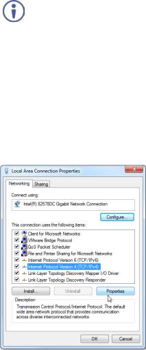
3.Highlight the network adapter you want to use to connect to the device and click Change settings of this connection.
The Local Area Connection Properties window for the selected network adapter appears as shown in Figure 4.
Figure 4: Local Area Connection Properties Window
10 |
VS-42UHD - Connecting the VS-42UHD |
4.Highlight Internet Protocol Version 4 (TCP/IPv4) by clicking on the item.
5.Click Properties.
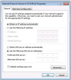
The Internet Protocol Properties window appears as shown in Figure 5.
Figure 5: Internet Protocol Version 4 Properties Window
6.Select Use the following IP Address for static IP addressing and fill in the details as shown in Figure 6.
For TCP/IPv4 you can use any IP address in the range 192.168.1.1 to 192.168.1.255 (excluding 192.168.1.39) that is provided by your IT department.
VS-42UHD - Connecting the VS-42UHD |
11 |

Figure 6: Internet Protocol Properties Window
7.Click OK.
8.Click Close.
4.2.2Connecting the Ethernet Port via a Network Hub or Switch
You can connect the Ethernet port of the VS-42UHD to the Ethernet port on a network hub or using a straight-through cable with RJ-45 connectors.
4.3Connecting the Remote Contact-Closure Switches
You can connect up to four remote, contact-closure switches per output to control the VS-42UHD remotely. These switches replicate the Input selection buttons on the front panel of the VS-42UHD.
12 |
VS-42UHD - Connecting the VS-42UHD |

Figure 7 illustrates the wiring of the switch connections to the terminal block.
Figure 7: Remote Contact-closure Switch Connections
VS-42UHD - Connecting the VS-42UHD |
13 |

5 Principles of Operation
This section describes the operating theory of the VS-42UHD and includes:
•Automatic signal detection (see Section 5.1)
•Input switching modes (see Section 5.2)
•EDID operation (see Section 5.3)
5.1Automatic Signal Detection
The VS-42UHD can automatically detect the presence of a video signal on an input based on the presence of a video sync or clock signal.
5.2Input Switching Modes
5.2.1Manual Mode
In Manual switching mode, routing is performed according to the front panel button selection or according to the remote command selection.
5.2.2Automatic Mode
Automatic switching can be performed in either of the following ways:
•Input priority. Upon detection of an active input, the input with the highest priority is automatically selected. Input priority is from the lowest input number
(1) to the highest (4)
•Last Connected. The device automatically selects the most recently connected input. Should this source become inactive, the device automatically switches to the last connected input that was active. When turning the device on and more than one input is active, the input with the highest priority is selected
If a manual selection is made when the device is in Automatic mode, the device enters Manual Override mode. The manually selected input remains selected as long as it is active. When a manually selected input becomes inactive, the device returns to Automatic mode.
14 |
VS-42UHD - Principles of Operation |
5.3EDID Operation
The VS-42UHD has a default EDID (see Section 12) stored on all inputs. This EDID can be exchanged for either:
•A custom EDID which is uploaded to one or more inputs using Protocol 3000 commands (see Section 13.3.5)
–OR–
•The EDID of a display device connected to an output by using either the front panel buttons (see Section 6.2), a Protocol 3000 command, or the Web pages
The EDID is non-volatile and the last valid EDID is used when the device is powered up.
5.4Step-in Functionality
The VS-42UHD can function as a step-in switcher when connected to a suitable HDMI transmitter, (for example, the SID-X3N or DIP-31) using the correct HDMI cable with HEC support.
Use the Web pages (see Section 8.2.2) to assign remote device button actions. The default button actions are shown in the following table. Up to three buttons can be active at the same time.
Command |
Action |
|
Echo |
Allows a connected controller to be programmed to perform a variety of |
|
|
tasks triggered by the user buttons, such as, room control, (lights, |
|
|
screen, and so on) |
|
Out1 |
Step in current input to Output 1 |
|
Out2 |
Step in current input to Output 2 |
VS-42UHD - Principles of Operation |
15 |
6Operating the VS-42UHD 4x2 HDMI Matrix Switcher
This section describes operating the VS-42UHD and consists of:
•Switching an input to an output (see Section 6.1)
•Acquiring an EDID from an output (see Section 6.2)
•Muting and unmuting the outputs (see Section 6.3)
•Locking and unlocking the front panel buttons (see Section 6.4)
•Generating a test pattern (see Section 6.5)
6.1Switching an Input to an Output
To switch an input to an output, (for example, Input 4 to Output 2):
•Press the Input 4 button in the bottom Output (To OUT 2) row. The LED lights red and Input 4 is switched to Output 2
6.2Acquiring an EDID from an Output
You can acquire the EDID from OUT 1 or OUT 2 and copy it to any or all of the four inputs to be stored in non-volatile memory. You can also reset any or all of the inputs to the default EDID.
To copy the EDID from an Output to one or more Inputs:
1.Press the EDID button to enter the EDID setting mode.
The EDID button lights.
Note: If there is no button activity for 10 seconds, the device automatically exits the EDID setting mode to normal operation, the EDID button no longer lights and any changes made are lost.
2.From the To OUT 1 (top) row, press each of the Inputs to which you want to copy the EDID from Output 1.
Each selected Input LED lights.
16 |
VS-42UHD - Operating the VS-42UHD 4x2 HDMI Matrix Switcher |
Loading...