


 Loading...
USER MANUAL
MODELS:
KDS-EN6
Video Encoder
KDS-DEC6
Video Decoder
P/N: 2900-300655 Rev 2 |
www.KramerAV.com |

Contents
1 |
Introduction |
1 |
2 |
Getting Started |
2 |
2.1 |
Achieving the Best Performance |
2 |
2.2 |
Safety Instructions |
3 |
2.3 |
Recycling Kramer Products |
3 |
3 |
Overview |
4 |
3.1 |
Defining KDS-EN6 |
5 |
3.2 |
Defining KDS-DEC6 |
6 |
4 |
Initial Setup |
8 |
4.1 |
Initial Setup via Channel Buttons |
8 |
4.2 |
Initial Setup via Web Pages |
10 |
5 |
Connecting the KDS-EN6 and KDS-DEC6 |
12 |
5.1 |
KDS-DEC6/KDS-EN6 Unicast Installation |
13 |
5.2 |
One-to-Many Configuration |
16 |
5.3 |
Matrix Configuration |
17 |
5.4 |
Video Wall Setup |
18 |
5.5 |
KVM Setup |
22 |
6 |
Using the Embedded Web Pages |
23 |
6.1 |
Modifying and Viewing the System |
23 |
6.2 |
Setting the Video Wall |
31 |
6.3 |
Setting Up the Network |
37 |
6.4 |
Setting the Operation Functions |
38 |
7 |
Operating the KDS-EN6 and KDS-DEC6 |
45 |
7.1 |
Setting Up RS-232 over IP |
45 |
7.2 |
Setting Up USB over IP |
50 |
7.3 |
Setting Up IR over IP |
50 |
7.4 |
Fast Video Switching |
50 |
7.5 |
Resetting the KDS-EN6/ KDS-DEC6 to Factory Default Values |
51 |
8 |
Technical Specifications |
52 |
Figures
Figure 1: KDS-EN6 Video Encoder Front Panel |
5 |
Figure 2: KDS-EN6 Video Encoder Rear Panel |
5 |
Figure 3: KDS-DEC6 Video Decoder Front Panel |
6 |
Figure 4: KDS-DEC6 Video Decoder Rear Panel |
7 |
Figure 5: Connecting an Encoder and Decoder System |
15 |
Figure 6: Connecting a One-to-Many System |
16 |
Figure 7: Connecting a Daisy-Chain System |
17 |
Figure 8: Connecting the KDS-EN6, KDS-DEC6 Video Encoder |
18 |
Figure 9: Video Wall Setup |
20 |
Figure 10: KVM Setup |
22 |
Figure 11: The System Tab – Version Information |
24 |
Figure 12: The System Tab – Firmware upgrade |
25 |
Figure 13: The System Tab – selecting the Firmware File |
25 |
Figure 14: The System Tab – Utilities for KDS-DEC6 |
26 |
Figure 15: The System Tab – Utilities Window for KDS-EN6 |
27 |
|
|
KDS-DEC6 – Contents |
i |
|
|
Figure 16: The System Tab – Utilities, Machine State and Network Information |
29 |
Figure 17: The System Tab – Utilities, Video Information |
30 |
Figure 18: The System Tab – Video Wall, Basic Setup |
32 |
Figure 19: The System Tab – Video Wall, Applying the Basic Setup to a Device |
33 |
Figure 20: Video Wall Tab – Advanced Setup, Selecting a specific Device, Column or Row35
Figure 21: Video Wall Tab – Advanced Setup Configuration |
36 |
|
Figure 22: Network Tab – IP Setup |
37 |
|
Figure 23: The Network Tab – Casting Mode |
38 |
|
Figure 24: Functions Tab – Video over IP for KDS-DEC6 |
39 |
|
Figure 25: The Functions Tab – Video over IP for KDS-EN6 |
40 |
|
Figure 26: The Functions Tab – USB over IP for KDS-DEC6 |
41 |
|
Figure 27: The Functions Tab – USB over IP for KDS-EN6 |
42 |
|
Figure 28: The Functions Tab – RS-232 over IP |
43 |
|
Figure 29: Serial over IP – RS-232 over IP |
45 |
|
Figure 30: Serial over IP – Type 1 |
Operation Mode |
46 |
Figure 31: Serial over IP – Type 2 connection |
47 |
|
Figure 32: Serial over IP – Type 2 |
Operation Mode |
48 |
Figure 33: Serial over IP – Type 2 |
Guest connection |
49 |
Figure 34: Serial over IP – Type 2 Guest Operation Mode |
49 |
|
ii |
KDS-DEC6 – Contents |

1 Introduction
Welcome to Kramer Electronics! Since 1981, Kramer Electronics has been providing a world of unique, creative, and affordable solutions to the vast range of problems that confront video, audio, presentation, and broadcasting professionals on a daily basis. In recent years, we have redesigned and upgraded most of our line, making the best even better!
Our 1,000-plus different models now appear in 14 groups that are clearly defined by function: GROUP 1: Distribution Amplifiers; GROUP 2: Switchers and Routers; GROUP 3: Control Systems; GROUP 4: Format/Standards Converters; GROUP 5: Range Extenders and Repeaters; GROUP 6: Specialty AV Products; GROUP 7:
Scan Converters and Scalers; GROUP 8: Cables and Connectors; GROUP 9: Room Connectivity; GROUP 10: Accessories and Rack Adapters; GROUP 11: Sierra Video Products; GROUP 12: Digital Signage; GROUP 13: Audio; and GROUP 14: Collaboration.
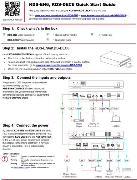
Congratulations on purchasing your Kramer KDS-EN6 Video Encoder and KDSDEC6 Video Decoder, which are ideal for the following typical applications:
•Real-time essential installations such as sports bars and interactive solutions.
•AV distribution systems with one or more sources and many displays in schools, universities, and public venues.
•Long-distance transmission of signals using existing wires and infrastructure in corporate offices or government applications.
•Advanced applications requiring recording, archiving, scaling and more.
KDS-EN6, KDS-DEC6 - Introduction |
1 |
2 Getting Started
We recommend that you:
•Unpack the equipment carefully and save the original box and packaging materials for possible future shipment
•Review the contents of this user manual
Go to www.kramerav.com/downloads/KDS-DEC6 to check for up-to-date user manuals, application programs, and to check if firmware upgrades are available (where appropriate).
2.1Achieving the Best Performance
To achieve the best performance:
•Use only good quality connection cables (we recommend Kramer highperformance, high-resolution cables) to avoid interference, deterioration in signal quality due to poor matching, and elevated noise levels (often associated with low quality cables)
•Do not secure the cables in tight bundles or roll the slack into tight coils
•Avoid interference from neighboring electrical appliances that may adversely influence signal quality
•Position your Kramer KDS-EN6 / KDS-DEC6 away from moisture, excessive sunlight and dust
This equipment is to be used only inside a building. It may only be connected to other equipment that is installed inside a building.
2 |
KDS-EN6, KDS-DEC6 - Getting Started |

2.2Safety Instructions
Caution: There are no operator serviceable parts inside the unit
Warning: Use only the Kramer Electronics power supply (purchased separately)
Warning: Disconnect the power and unplug the unit from the wall before installing
2.3Recycling Kramer Products
The Waste Electrical and Electronic Equipment (WEEE) Directive 2002/96/EC aims to reduce the amount of WEEE sent for disposal to landfill or incineration by requiring it to be collected and recycled. To comply with the WEEE Directive, Kramer Electronics has made arrangements with the European Advanced Recycling Network (EARN) and will cover any costs of treatment, recycling and recovery of waste Kramer Electronics branded equipment on arrival at the EARN facility. For details of Kramer’s recycling arrangements in your particular country go to our recycling pages at www.kramerav.com/support/recycling/.
KDS-EN6, KDS-DEC6 - Getting Started |
3 |

3 Overview
Kramer MegaTOOL® KDS-EN6 Encoder and KDS-DEC6 Decoder units provide AV over IP network and include 4K video, audio, IR, RS-232 and USB over IP with HDCP 2.2.
KDS-EN6 / KDS-DEC6 features:
•Video Support − HDMI 4K@60Hz (4:2:0), HDMI 4K@30Hz (4:4:4).
•Audio Support − HDMI/line in, 7.1 PCM, Dolby True−HD, and DTS−HD
Master audio.
•Virtualization − IR, USB, RS−232 over IP.
•Network − Managed switch, 1G, multicast, jumbo frames, IGMP snooping layer 2.
•Power − PoE or external power supply.
•Control − Kramer Network, Kramer Control, Web UI, API.
•HDCP − 2.2 compliance.
•Flexible video wall setups.
•Size − MegaTOOLS® letting you mount two units side-by-side in a 1U rack space with the optional RK-T2B rack adapter.
4 |
KDS-EN6, KDS-DEC6 - Overview |
3.1Defining KDS-EN6
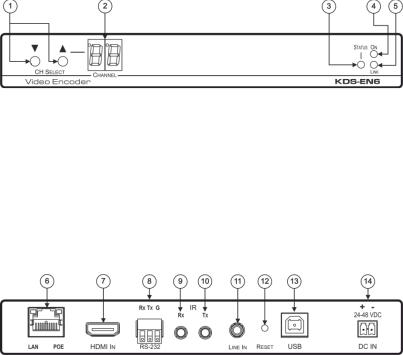
Figure 1: KDS-EN6 Video Encoder Front Panel
# |
|
Feature |
|
Function |
1 |
|
CH SELECT Buttons |
|
Press the up or down arrow buttons to select the channel ID |
2 |
|
CHANNEL Display |
|
Displays the selected channel. If the channel number exceeds |
|
|
|
|
99, the 100 indicator turns on (for example, channel 124 |
|
|
|
|
appears as “°24”) |
3 |
|
STATUS LED |
|
Identifies a device in a system. When sending a P3K FIND-ME |
|
|
|
|
command to the system, the LED of the device to be identified |
|
|
|
|
flashes for 5 seconds |
4 |
|
ON LED |
|
Flashes during power up and lights when on |
5 |
|
LINK LED |
|
On when a KDS-EN6 to KDS-DEC6 link is established and is |
|
|
|
|
transmitting A/V signals |
Figure 2: KDS-EN6 Video Encoder Rear Panel
|
# |
|
Feature |
|
Function |
|
|
|
|
6 |
|
LAN/POE RJ-45 Connector |
|
Connect the KDS-EN6 to the network using |
|
||
|
|
|
|
|
recommended Kramer cables. Note that this port |
|
||
|
|
|
|
|
supports power over Ethernet (PoE) |
|
||
|
|
|
|
|
LAN LED |
Green LED flashes during data transmission |
|
|
|
|
|
|
|
POE LED |
Orange LED lights when power is supplied |
|
|
|
7 |
|
HDMI IN Connector |
|
Connect an HDMI source |
|
||
|
8 |
|
RS-232 (Rx,Tx,Gnd) Terminal |
|
Connect to an RS-232 controller device (to control a |
|
||
|
|
|
Block Connectors |
|
device on the decoder side) |
|
||
|
9 |
|
IR RX on a 3.5mm Mini Jack |
|
Connect to a receiver |
|
||
|
10 |
|
IR TX on a 3.5mm Mini Jack |
|
Connect to an emitter |
|
||
|
11 |
|
LINE In on a 3.5mm Mini Jack |
|
Connect to an audio source |
|
||
|
12 |
|
RESET Button |
|
Press to reset KDS-EN6 to its default settings |
|
||
|
13 |
|
USB Type B Port |
|
Connect to a USB host, for example, a PC |
|
||
|
14 |
|
DC IN 24~48VDC Power |
|
Connect to the Kramer power adapter (DC voltage range |
|
||
|
|
|
Terminal Block Connector |
|
should be 24V to 48V), purchased separately |
|
||
|
|
|
|
|
(PN: 60-0009390) |
|
||
|
|
|
|
|
|
|
|
|
KDS-EN6, KDS-DEC6 - Overview |
|
|
|
5 |
|
|||
|
|
|
|
|
|
|
|
|
3.2Defining KDS-DEC6
Figure 3: KDS-DEC6 Video Decoder Front Panel
# |
Feature |
Function |
|
1 |
IR TX on a 3.5mm Mini Jack |
Connect to an emitter |
|
2 |
IR RX on a 3.5mm Mini Jack |
Connect to a receiver |
|
3 |
RESET Button |
Press to reset KDS-DEC6 to its default settings |
|
4 |
CH Select Buttons |
Press the arrow buttons up or down to select the channel ID |
|
5 |
CHANNEL Display |
Displays the selected channel. If the channel number |
|
|
|
exceeds 99, the 100 indicator turns on (for example, channel |
|
|
|
125 appears as “°25”) |
|
6 |
USB Type A Ports (2) |
Connect to a mouse and keyboard |
|
7 |
STATUS LED |
Identifies a device in a system. When sending a P3K |
|
|
|
FIND-ME command to the system, the LED of the device to |
|
|
|
be identified flashes for 5 seconds |
|
8 |
ON LED |
Flashes during power up and lights when on |
|
9 |
LINK LED |
On when a KDS-EN6 to KDS-DEC6 link is established and |
|
|
|
transmitting A/V signals |
6 |
KDS-EN6, KDS-DEC6 - Overview |
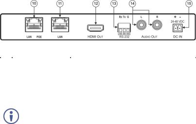
Figure 4: KDS-DEC6 Video Decoder Rear Panel
# |
Feature |
|
Function |
|
10 |
LAN/POE RJ-45 |
|
Connect the KDS-EN6 to the network using the |
|
|
Connector |
|
recommended Kramer cable. Note that this port supports |
|
|
|
|
power over Ethernet (PoE) |
|
|
|
|
LAN LED |
Green LED flashes during data transmission |
|
|
|
POE LED |
Orange LED lights when power is supplied |
11 |
LAN RJ-45 Connector |
|
Connect the KDS-DEC6 to the network or directly to the |
|
|
|
|
KDS-EN6 using the recommended Kramer cable. |
|
|
Use the LAN port (that is not used for connecting to the network or directly to the |
|||
|
encoder) to connect to the next KDS-DEC6 device in a daisy chain configuration |
|||
|
|
|
|
|
12 |
HDMI Out Connector |
|
Connect to an HDMI acceptor |
|
13 |
RS-232 (Rx,Tx,Gnd) on |
|
Connect to an RS-232 controlled device |
|
|
Terminal Block Connectors |
|
|
|
14 |
L, R Audio on RCA |
|
Connect to a powered speaker or an amplifier |
|
|
Connectors |
|
|
|
15 |
DC IN 24~48VDC Power |
|
Connect to the Kramer power adapter (DC voltage range |
|
|
Terminal Block Connector |
|
should be 24V to 48V), purchased separately |
|
|
|
|
(PN: 60-0009390 |
|
KDS-EN6, KDS-DEC6 - Overview |
7 |

4 Initial Setup
Before installing the KDS-EN6/KDS-DEC6:
•Set a static IP address or set it automatically via DHCP.
•Set the channel number.
If the channel number exceeds 99, the indicator on the display lights.
The KDS-EN6 and KDS-DEC6 can be powered either via PoE (using the RJ-45 LAN/POE port) if available or via a 24-48V DC power adapter.
If 24-48V DC power is connected, PoE is disabled automatically.
KDS-EN6 and KDS-DEC6 IP address and channel number can be set using:
•The channel buttons on the KDS-EN6 / KDS-DEC6, see Section 4.1.
•The embedded web pages, see Section 4.2.
4.1Initial Setup via Channel Buttons
The initial setup includes setting the following:
•IP address
•Channel number
4.1.1Setting the IP Address
To set the KDS-EN6 / KDS-DEC6 IP address via channel buttons:
1.Connect the KDS-EN6 / KDS-DEC6 LAN/POE RJ-45 port to your network (if your network does not support PoE, connect a 24-48V DC power adapter). The ON LED lights green and the LINK flashes (indicating that no streaming activity is detected).
2.Press and hold for 3 seconds.
3.Press or to select DH (DHCP) or SC (static) IP address setup.
8 |
KDS-EN6, KDS-DEC6 - Initial Setup |

4.If you selected DHCP (for Static, go to the next step):
For KDS-DEC6, press and hold or for 3 seconds to save your selection.
The channel display flashes “--” 3 times and the device reboots.
For KDS-EN6, the channel display flashes “ID” 3 times. Continue to set the channel number for the KDS-EN6.
When setting to DHCP we recommend that you contact your IT administrator for setting the system IP addresses.
5.If you selected Static, press and hold or for 3 seconds to save your selection.
The channel display flashes “IP” 3 times and the device reboots.
6.Press or to set the IP address.
You can only define the last three digits of the IP address when setting the IP address via the channel buttons. To change the entire IP address, go to Section 4.2.1).
7.Press and hold and for 3 seconds to save your selection.
4.1.2Setting the Channel Number
The KDS-DEC6 channel number is set by simply pressing the or buttons at any time.
The KDS-EN6 channel number can be set immediately after the IP address is set (via either static or DHCP).
To set the channel number for the encoder:
1.Wait until the channel display flashes “ID” 3 times.
2.Press or to select the channel number.
3.Press and hold and for 3 seconds to save your selection. The channel display flashes “--” 3 times and the device reboots.
KDS-EN6, KDS-DEC6 - Initial Setup |
9 |

4.1.3Viewing the IP Address and Channel Number
You can view the current IP address and channel number any time.
To view the IP address and channel number:
1.Press and hold for 3 seconds.
2.The channel display shows “IP” for 3 seconds and then shows the IP address for 3 seconds followed by the channel number.
4.2Initial Setup via Web Pages
Use the web pages to set the:
•IP address, see Section 4.2.1.
•Channel numbers, see Section 4.2.2.
4.2.1Setting the IP Address via Web Pages
Using the embedded web pages you can change the entire IP address.
To set the IP address:
1.Connect the KDS-EN6 / KDS-DEC6 Ethernet port to the Network and power the device (either by using the power adapter or via PoE).
2.Access the embedded Web pages (see Section 6).
3.In the Network tab (see Section 6.3) select the IP mode.
4.If you selected Static, type in the IP address.
When setting to DHCP we recommend that you contact your IT administrator for setting the system IP addresses.
5.Click Apply and reboot the device.
4.2.2Setting the Channel Number via Web Pages
Use API commands to set channel numbers.
10 |
KDS-EN6, KDS-DEC6 - Initial Setup |

A KDS-EN6 channel number usually remains constant during normal operation. However, a KDS-DEC6 channel number must be modified according to the channel number of the currently linked encoder (for example, in a matrix configuration). This enables linking to different encoders in the network
To set the channel number:
1.Connect the KDS-EN6 / KDS-DEC6 Ethernet port to the Network and power the device (either using the power adapter or via PoE).
2.Access the embedded Web pages (see Section 6).
3.In the System tab select Utilities (see Section 6.1.3).
4.In the Console API Command text box enter the following command: For the KDS-EN6:
"astparam s multicast_ip 225.0.100.X; astparam s hostname_id 000X; astparam s reset_ch_on_boot n; astparam save;"
where X=Channel number, for example:
for multicast_ip: 225.0.100.8 or 225.0.100.10 for hostname_id: 0008 or 0010
Click Apply.
Power cycle the device
For the KDS-DEC6:
"Switchto X"
where X=Channel number
Click Apply.
API commands can also be entered directly via Telnet. The default is
Telnet port 24. Use "root" to log in. No password is required.
KDS-EN6, KDS-DEC6 - Initial Setup |
11 |

5 Connecting the KDS-EN6 and KDS-DEC6
Always switch off the power to each device before connecting it to your KDS-DEC6. After connecting your KDS-DEC6, connect its power and then switch on the power to each device.
Before connecting the KDS-EN6 and KDS-DEC6 note that:
•When connecting KDS-EN6 to KDS-DEC6 via the Ethernet, use a 1 Giga LAN switch and make sure that jumbo frame (over 8k) and IGMP snooping are enabled.
•The BC-UNIKAT cable length connecting KDS-EN6/KDS-DEC6 to the network should not exceed 330 feet (100m).
•The KDS-EN6 operates with a default EDID. If you need to copy the EDID from the acceptor, do so via the Web pages.
Following the initial setup (see Section 4), you can configure the KDS-EN6 and KDS-DEC6 devices in any of the following ways:
•Unicast setup: single encoder-decoder unicast connection, see Section 5.1.
•Multicast configuration setup: a multicast setup can include any of the following configurations:
One encoder to many decoders, see Section 5.2.
Many encoders to many decoders (matrix switcher configuration), see Section 5.3.
Video wall configuration, see Section 5.4.
•KVM (Keyboard, Video, Mouse) setup: many encoders to a single decoder see Section 5.5.
12 |
KDS-EN6, KDS-DEC6 - Connecting the KDS-EN6 and KDS-DEC6 |

5.1KDS-DEC6/KDS-EN6 Unicast Installation
You can use one KDS-EN6 device and one KDS-DEC6 device to configure an encoder and decoder system (see Figure 5).
The encoder and decoder devices can be connected directly or via LAN.
Always switch off the power to each device before connecting it to your
KDS-DEC6/KDS-EN6. After connecting your KDS-DEC6/KDS-EN6, connect its power and then switch on the power to each device.
To connect the encoder and decoder system as shown in the example in Figure 5:
1.On the KDS-EN6, connect an HDMI source (for example, a media player) to the HDMI IN connector.
2.On the KDS-DEC6, connect the HDMI OUT connector to an HDMI acceptor (for example, a display).
3.Connect the LAN RJ-45 connector on the KDS-DEC6 directly to the LAN RJ-45 connector on the KDS-EN6 using an Ethernet cable (or via LAN).
4.If you are not powering the device via PoE, connect the KDS-DEC6 and the KDS-EN6 to the 24-48V DC power adapter and connect the adapter to the mains electricity (not shown in Figure 5).
5.If required, connect a PC and/or controller to the RS-232 terminal block connector on the KDS-EN6.
6.If required, connect the USB ports:
On the KDS-EN6 connect a PC to the USB type B port.
On the KDS-DEC6 connect a mouse and a keyboard to the two USB type A ports.
7.If required, connect an unbalanced stereo audio source to the
KDS-EN6 (for example, the media player’s audio signal) and an unbalanced stereo audio acceptor (for example, speakers) to the KDS-DEC6.
You do not have to use all the possible control options.
KDS-EN6, KDS-DEC6 - Connecting the KDS-EN6 and KDS-DEC6 |
13 |
Loading...