


 Loading...
USER MANUAL
MODEL:
VSM-4x4HFS
4x4 Seamless Matrix Switcher/Multi-Scaler
P/N: 2900-300362 Rev 3 |
www.kramerAV.com |
Contents
1 |
Introduction |
1 |
2 |
Getting Started |
2 |
2.1 |
Achieving the Best Performance |
2 |
2.2 |
Safety Instructions |
3 |
2.3 |
Recycling Kramer Products |
3 |
3 |
Overview |
4 |
3.1 |
Defining the VSM-4x4HFS |
5 |
4 |
Installing in a Rack |
8 |
5 |
Connecting and Operating the VSM-4x4HFS |
9 |
5.1 |
The Matrix Mode |
9 |
5.2 |
The Video Wall Mode |
11 |
5.3 |
The Dual Mode |
14 |
5.4 |
The QUAD Mode |
16 |
6 |
Controlling the VSM-4x4HFS |
18 |
6.1 |
Controlling via the Front Panel Buttons |
18 |
6.2 |
Using the OSD Menu |
24 |
6.3 |
Connecting to the VSM-4x4HFS via RS-232 |
28 |
6.4 |
Operating via Ethernet |
29 |
6.5 |
Controlling via the Infrared Remote Control Transmitter |
33 |
6.6 |
Using the IR Remote Control in the Dual Mode |
34 |
7 |
Firmware Upgrade via USB |
39 |
8 |
Using the Embedded Web Pages |
40 |
8.1 |
Browsing the VSM-4x4HFS Web Pages |
40 |
8.2 |
The Routing Page |
41 |
8.3 |
The Device Settings Page |
48 |
8.4 |
The Output Settings Page |
51 |
8.5 |
The HDCP Settings Page |
53 |
8.6 |
The EDID Management Page |
54 |
8.7 |
The About Page |
56 |
8.8 |
Save or Upload a Configuration |
56 |
9 |
Technical Specifications |
57 |
9.1 |
Default Communication Parameters |
57 |
9.2 |
Table of Supported Input Resolutions |
58 |
9.3 |
Table of Supported Output Resolutions |
58 |
10 |
The VSM-4x4HFS RS-232/Ethernet (UDP) Communication Protocol |
59 |
10.1 |
Protocol 3000 |
59 |
10.2 |
Kramer Protocol 3000 – Detailed Commands |
64 |
VSM-4x4HFS – Contents |
i |
|
|
Figures
Figure 1: VSM-4x4HFS 4x4 Seamless Matrix Switcher/Multi-Scaler Front Panel |
6 |
Figure 2: VSM-4x4HFS 4x4 Seamless Matrix Switcher/Multi-Scaler Rear Panel |
7 |
Figure 3: Connecting the VSM-4x4HFS Presentation Switcher / Scaler |
10 |
Figure 4: The VSM-4x4HFS Video Wall Operation Mode |
11 |
Figure 5: Connecting the VSM-4x4HFS in the Video Wall Operation Mode |
12 |
Figure 6: VSM-4x4HFS Bezel Correction |
13 |
Figure 7: Connecting the VSM-4x4HFS in the Dual Operation Mode |
15 |
Figure 8: the VSM-4x4HFS QUAD Operation Mode Input Orientation |
16 |
Figure 9: Connecting the VSM-4x4HFS in the Quad Operation Mode |
17 |
Figure 10: Local Area Connection Properties Window |
30 |
Figure 11: Internet Protocol Version 4 Properties Window |
31 |
Figure 12: Internet Protocol Version 6 Properties Window |
31 |
Figure 13: Internet Protocol Properties Window |
32 |
Figure 14: Infrared Remote Control Transmitter |
33 |
Figure 15: IR Remote Control Transmitter Dual Mode Shortcuts |
34 |
Figure 16: The Routing Page |
41 |
Figure 17: The Matrix Tab output Resolution |
42 |
Figure 18: The Matrix Tab – Set the Output Resolution |
43 |
Figure 19: The Matrix Tab – the Input Edit Window |
43 |
Figure 20: The Matrix Tab – Type the new label |
43 |
Figure 21: The Matrix Tab – View the LabelDVD |
44 |
Figure 22: The Matrix Tab – Store a Configuration |
44 |
Figure 23: The Matrix Tab – Recall a Configuration |
45 |
Figure 24: The Video Wall Tab |
45 |
Figure 25: The Video Wall Tab – Bezel Correction |
46 |
Figure 26: The Dual Tab – POP Mode |
46 |
Figure 27: The Dual Tab – PIP Mode |
47 |
Figure 28: The Dual Tab – PIP Position |
47 |
Figure 29: The Quad Tab |
48 |
Figure 30: The Device Settings Page |
48 |
Figure 31: The Device Settings Page – Ethernet Settings |
49 |
Figure 32: The Device Settings Page – IP Number Settings |
49 |
Figure 33: The Device Settings Page – the Information Window |
50 |
Figure 34: The Device Settings Page – Factory Reset Message |
50 |
Figure 35: The Device Settings Page – Factory Reset |
50 |
Figure 36: The Output Settings Page – Matrix and Video Wall Modes |
51 |
Figure 37: The Output Settings Page – Dual Mode |
52 |
Figure 38: The Output Settings Page – Quad Mode |
52 |
Figure 39: The HDCP Settings Page |
53 |
Figure 40: The EDID Page |
54 |
Figure 41: The EDID Page – Copying the Native Timing |
54 |
Figure 42: The EDID Page – Copying the Default |
55 |
Figure 43: The EDID Page –The Copy EDID Results |
55 |
Figure 44: The About Page |
56 |
Figure 45: Loading a Configuration |
56 |
ii |
VSM-4x4HFS - Contents |
|
|

1 Introduction
Welcome to Kramer Electronics! Since 1981, Kramer Electronics has been providing a world of unique, creative, and affordable solutions to the vast range of problems that confront video, audio, presentation, and broadcasting professionals on a daily basis. In recent years, we have redesigned and upgraded most of our line, making the best even better!
Our 1,000-plus different models now appear in 14 groups that are clearly defined by function: GROUP 1: Distribution Amplifiers; GROUP 2: Switchers and Routers; GROUP 3: Control Systems; GROUP 4: Format/Standards Converters; GROUP 5: Range Extenders and Repeaters; GROUP 6: Specialty AV Products; GROUP 7: Scan Converters and Scalers; GROUP 8: Cables and Connectors; GROUP 9: Room Connectivity; GROUP 10: Accessories and Rack Adapters; GROUP 11: Sierra Video Products; GROUP 12: Digital Signage; GROUP 13: Audio; and GROUP 14: Collaboration.
Congratulations on purchasing your Kramer VSM-4x4HFS 4x4 Seamless Matrix Switcher/Multi-Scaler.
The VSM-4x4HFS, which incorporates HDMI™ technology, is ideal for:
Conference room presentations
Advertising applications, shopping malls and museums
Post production applications
Rental and staging
Security applications
Video-wall scaling
Applications with multiple inputs and outputs
Applications where quick, sleek, seamless switching is required
Any application requiring 4 scalers in a single 1RU rack space
VSM-4x4HFS – Introduction |
1 |
|
|

2 Getting Started
We recommend that you:
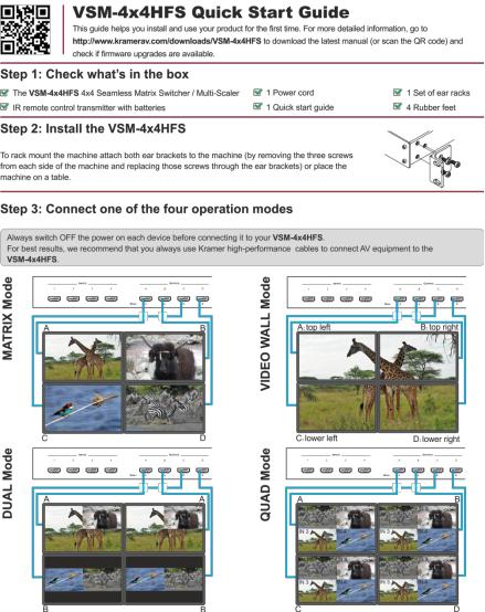
Unpack the equipment carefully and save the original box and packaging materials for possible future shipment
Review the contents of this user manual
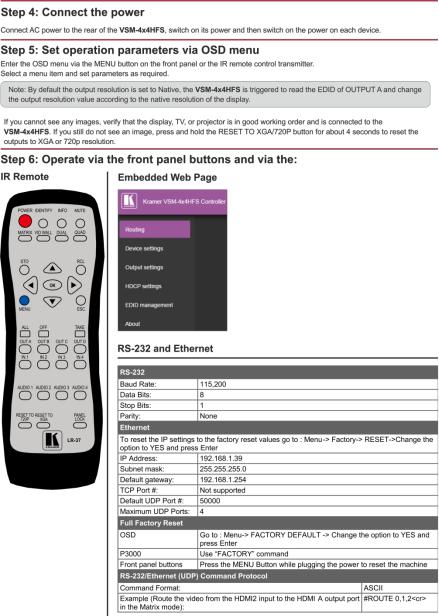
Go to http://www.kramerav.com/downloads/VSM-4x4HFS to check for up- to-date user manuals, application programs, and to check if firmware upgrades are available (where appropriate).
2.1Achieving the Best Performance
To achieve the best performance:
Use only good quality connection cables (we recommend Kramer highperformance, high-resolution cables) to avoid interference, deterioration in signal quality due to poor matching, and elevated noise levels (often associated with low quality cables)
Do not secure the cables in tight bundles or roll the slack into tight coils
Avoid interference from neighbouring electrical appliances that may adversely influence signal quality
Position your Kramer VSM-4x4HFS away from moisture, excessive sunlight and dust
This equipment is to be used only inside a building. It may only be connected to other equipment that is installed inside a building.
2 |
VSM-4x4HFS - Getting Started |
|
|

2.2Safety Instructions
Caution: There are no operator serviceable parts inside the unit
Warning: Use only the power cord that is supplied with the unit
Warning: Do not open the unit. High voltages can cause electrical shock! Servicing by qualified personnel only
Warning: Disconnect the power and unplug the unit from the wall before installing
2.3Recycling Kramer Products
The Waste Electrical and Electronic Equipment (WEEE) Directive 2002/96/EC aims to reduce the amount of WEEE sent for disposal to landfill or incineration by requiring it to be collected and recycled. To comply with the WEEE Directive, Kramer Electronics has made arrangements with the European Advanced Recycling Network (EARN) and will cover any costs of treatment, recycling and recovery of waste Kramer Electronics branded equipment on arrival at the EARN facility. For details of Kramer’s recycling arrangements in your particular country go to our recycling pages at http://www.kramerelectronics.com/support/recycling/.
VSM-4x4HFS – Getting Started |
3 |
|
|

3 Overview
The VSM-4x4HFS is a high−performance 4x4 Seamless Matrix Switcher/MultiScaler that allows switching between inputs via a clean video CUT (frame-to-frame switching with no glitches). The VSM-4x4HFS can perform as a matrix switcher, a 2x2 video wall, and also features dual and quad multi-viewing options.
It supports HDMI resolutions with deep color and up to 8 channels of audio, and supports per-port HDCP and EDID settings.
The VSM-4x4HFS features:
PixPerfect™ scaling technology – Kramer’s precision pixel mapping and high quality scaling technology
HDTV compatibility
HDCP compliance – The HDCP (High Definition Content Protection) license agreement allows copy−protected data on the HDMI input to pass only to the
HDMI outputs
4 HDMI inputs and four scaled HDMI outputs
Selectable operation modes – seamless matrix switcher, video wall, dual display (Split/PIP/POP) or quad display
Bezel correction options – in the video wall mode
HDMI support for Deep Color, Dolby Digital Plus, DTS, DTS−HD®, LPCM
2CH/6CH/8CH, AC3
HDCP and EDID settings per port
VGA to WUXGA and 480i to 1080p Input resolution range
480p to 1080p Output resolution range
Multiple aspect ratio selections - full, 4:3, 16:9 and best fit
Built-in ProcAmp - color, hue, sharpness, noise, contrast and brightness
Front panel control – operation mode, TAKE button, and menu buttons
4 preset memory locations for each operation mode for quick access to common IN-OUT configurations
4 |
VSM-4x4HFS - Overview |
|
|
Front panel lockout
Non-volatile memory – saves final settings
Program mini USB connector for firmware upgrade
Control your VSM-4x4HFS:
Directly, via the front panel push buttons
By RS-232 serial commands transmitted by a touch screen system, PC, or other serial controller
Remotely, from the infrared remote control transmitter with OSD (on-screen display)
Via the Ethernet with built-in Web pages
The VSM-4x4HFS is housed in a 19” 1U rack mountable enclosure, with rack “ears” included, and is fed from a 100-240 VAC universal switching power supply.
3.1Defining the VSM-4x4HFS
This section defines the VSM-4x4HFS.
VSM-4x4HFS – Overview |
5 |
|
|
6
Figure 1: VSM-4x4HFS 4x4 Seamless Matrix Switcher/Multi-Scaler Front Panel
|
|
# |
|
|
|
Feature |
|
|
|
|
|
Function |
|
||||||||||||||||||||||
|
|
|
|
|
|
|
|
|
|
|
|
|
|
|
|
|
|
|
|
|
|
|
|
|
|
|
|
|
|
|
|
|
|
|
|
|
1 |
|
|
IR LED |
|
|
|
|
Lights when the unit accepts IR remote commands |
||||||||||||||||||||||||||
|
|
|
|
|
IR Receiver |
|
|
Receives signals from the remote control transmitter |
|||||||||||||||||||||||||||
|
|
|
|
|
|
|
|
|
|
|
|
|
|
|
|
|
|
|
|
|
|
|
|
|
|
|
|
|
|||||||
|
2 |
|
|
OUTPUT/WINDOW |
|
In the MATRIX mode: select the output to which the input is switched (A, B, C or D) |
|||||||||||||||||||||||||||||
|
|
|
|
|
Selector Buttons |
|
In the VIDEO WALL mode: not used |
||||||||||||||||||||||||||||
|
|
|
|
|
|
|
|
|
|
|
In the DUAL mode: select one of the two DUAL windows: A or B for DUAL A; C or D for DUAL B (see Section 5.3) |
||||||||||||||||||||||||
|
|
|
|
|
|
|
|
|
|
|
In the QUAD mode: not used |
|
|
||||||||||||||||||||||
|
3 |
|
|
INPUT Selector Buttons |
|
Press to select an HDMI input (from 1 to 4) to switch to the output |
|||||||||||||||||||||||||||||
|
|
|
|
|
|
|
|
|
|
|
|
|
|
|
|
|
|
|
|
|
|
|
|
|
|
|
|
|
|
||||||
|
4 |
|
|
ALL Button |
|
|
Press ALL followed by an INPUT button to connect that input to all the outputs (not available for the video wall mode) |
||||||||||||||||||||||||||||
|
|
|
|
|
|
|
|
|
|
|
|
|
|
|
|
|
|
|
|
|
|
|
|
|
|
|
|
|
|
||||||
|
5 |
|
|
OFF Button |
|
|
Press after pressing an output button to disconnect the selected output from the inputs. To disconnect all the outputs, press ALL followed |
||||||||||||||||||||||||||||
|
|
|
|
|
|
|
|
|
|
|
by OFF |
||||||||||||||||||||||||
|
6 |
|
|
TAKE Button |
|
|
Press to toggle between the Confirm mode (when in the Confirm mode, the TAKE button lights ) and the At Once mode. When in TAKE |
||||||||||||||||||||||||||||
|
|
|
|
|
|
|
|
|
|
|
mode, front panel buttons actions are implemented after pressing the TAKE button (see Section 6.1.2) |
||||||||||||||||||||||||
|
|
|
|
|
|
|
|
|
|
|
|
|
|
|
|
|
|
|
|
|
|
|
|
|
|
|
|||||||||
|
7 |
|
|
MODE |
MATRIX |
|
Press to operate the system as a matrix switcher (see Section 5.1) |
||||||||||||||||||||||||||||
|
|
|
|
|
Buttons |
|
|
|
|
|
|
|
|
|
|
|
|
|
|
|
|
|
|
|
|
|
|
|
|
|
|
|
|
|
|
|
8 |
|
|
VIDEO WALL |
|
Press to operate as a 2x2 video wall (see Section 5.2) |
|||||||||||||||||||||||||||||
|
|
|
|
|
|
||||||||||||||||||||||||||||||
|
|
|
|
|
|
|
|
|
|
|
|
|
|
|
|
|
|
|
|
|
|
|
|
||||||||||||
|
9 |
|
|
|
|
DUAL |
|
Press to operate as a 4x2 switcher with PIP capabilities (see Section 5.3) |
|||||||||||||||||||||||||||
|
|
|
|
|
|
|
|
|
|
|
|
|
|
|
|
|
|
|
|
|
|
||||||||||||||
|
10 |
|
|
|
|
QUAD |
|
Press to display all four inputs on each of the outputs (see Section 5.4) |
|||||||||||||||||||||||||||
4x4HFS-VSM |
|
|
|
|
|
|
|
|
|
|
|
|
|
|
|
|
|
|
|
|
|
|
|
|
|
|
|
|
|
|
|
|
|
|
|
11 |
|
|
STO Button |
|
|
Press to store a configuration (see Section 6.1.3) |
|||||||||||||||||||||||||||||
|
|
|
|
|
|
|
|
|
|
|
|
|
|
|
|
|
|
||||||||||||||||||
|
12 |
|
|
RCL Button |
|
|
Press to recall a configuration (see Section 6.1.3) |
||||||||||||||||||||||||||||
|
|
|
|
|
|
|
|
|
|
|
|
|
|
|
|||||||||||||||||||||
|
13 |
|
|
IDENTIFY Button |
|
Press to indicate on each output, which input is displayed on the output. The display time is set via the OSD menu (see Section 6.2.1) |
|||||||||||||||||||||||||||||
|
|
|
|
|
|
|
|
|
|
|
|
|
|
|
|
||||||||||||||||||||
|
14 |
|
|
MENU |
|
|
|
|
Press to access the OSD menu, exit the OSD menu and, when in the OSD menu, move to the previous level in the OSD screen (see |
||||||||||||||||||||||||||
|
|
|
|
|
|
|
|
|
|
|
Section 6.1.2) |
||||||||||||||||||||||||
– |
|
|
|
|
|
|
|
|
|
|
|||||||||||||||||||||||||
15 |
|
|
Navigation |
ENTER |
|
Press to access sub-menu items and select from several settings (see Section 6.1.2) |
|||||||||||||||||||||||||||||
Overview |
|
|
|
|
Buttons |
|
|
|
|
|
|
|
|
|
|
|
|
|
|
|
|
|
|
|
|
|
|
|
|
|
|
|
|
|
|
|
|
|
|
|
|
|
|
|
|
|
|
|
|
|
|
|
|
|
|
|
|
|
|
|
|
|
|
|
|
|
|
|
|||
|
|
|
|
|
|
|
|
|
Press to decrease numerical values or select from several definitions |
||||||||||||||||||||||||||
|
|
|
|
|
|
|
|
|
|
||||||||||||||||||||||||||
|
|
|
|
|
|
|
|
|
|
|
Press to move up the menu list values (see Section 6.1.2) |
||||||||||||||||||||||||
|
|
|
|
|
|
|
|
|
|
|
|
|
|
|
|
|
|
|
|
|
|
|
|
|
|
|
|
|
|
|
|
|
|
|
|
4x4HFS-VSM |
|
|
|
|
|
|
|
|
|
|
|
|
|
|
|
# |
|
|
|
Feature |
|
|
|
Function |
|
||||
|
|
|
|
|
|
|
|
|
||||||
|
|
|
|
|
|
|
|
|
Press to increase numerical values or select from several definitions |
|||||
|
|
|
|
|
|
|
|
|
Press to move down the menu list (see Section 6.1.2) |
|||||
|
|
|
|
|
|
|
|
|
|
|||||
|
16 |
|
|
RESET TO XGA/720p |
|
Press and hold for about 4 seconds to toggle resetting the video resolution to XGA or 720p I |
||||||||
– |
|
|
|
|
Button |
|
|
|
|
|
|
|||
Overview |
17 |
|
|
PANEL LOCK Button |
|
Press and hold for about 2 seconds to lock/unlock the front panel buttons |
||||||||
|
|
|
|
|
|
|
|
|
|
|
|
|
|
|
|
|
|
|
|
|
|
|
|
|
|
|
|
|
|
Figure 2: VSM-4x4HFS 4x4 Seamless Matrix Switcher/Multi-Scaler Rear Panel
|
# |
|
|
Feature |
|
|
|
Function |
|
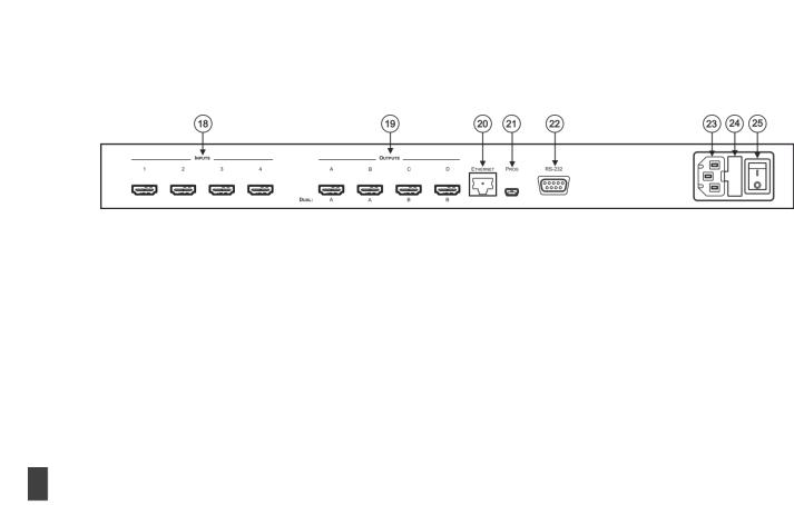
18 |
|
INPUT HDMI Connectors |
|
Connect to the HDMI sources (from 1 to 4) |
|||||
|
|
|
|
|
|||||
19 |
|
OUTPUT HDMI Connectors |
|
Connect to the HDMI acceptors (from A to D); DUAL: when in the dual operation mode, A, A and B, B |
|||||
20 |
|
ETHERNET Connector |
|
Connects to the PC or other Serial Controller through computer networking |
|||||
|
|
|
|
|
|||||
21 |
|
PROG USB Connector |
|
Connect to upgrade the unit |
|||||
22 |
|
RS-232 9-pin D-sub Port |
|
Connect to the PC or a remote controller |
|||||
|
|
|
|
|
|||||
23 |
|
Mains Socket |
|
Connect the mains power cord |
|||||
|
|
|
|
|
|||||
24 |
|
Mains Fuse Holder |
|
Fuse for protecting the device |
|||||
25 |
|
Power Switch |
|
Switch for turning the unit ON or OFF |
|||||
7

4 Installing in a Rack
This section provides instructions for rack mounting the unit.
8 |
VSM-4x4HFS - Installing in a Rack |
|
|

5 Connecting and Operating the VSM-4x4HFS
The VSM-4x4HFS is a four-in-one-box device. It can operate as a:
Matrix switcher
Video wall
Dual switcher
Quad switcher
You can select the different operation modes via front panel buttons, the IR remote control transmitter, the OSD menu or via the Web pages.
This section describes how to connect and operate the VSM-4x4HFS for operating in each of the four operation modes (see Section 5).
Always switch off the power to each device before connecting it to your VSM-4x4HFS. After connecting your VSM-4x4HFS, connect its power and then switch on the power to each device.
You do not have to connect all the inputs and outputs, connect only those that are required.
5.1The Matrix Mode
The VSM-4x4HFS matrix switcher mode is the default operation mode. Any of the four inputs can be switched to any of the four outputs. Switching is immediate and seamless.
5.1.1Connecting the VSM-4x4HFS in the Matrix Operation Mode
To connect the VSM-4x4HFS in the MATRIX mode, as illustrated in the example in Figure 3, do the following:
1.Connect up to four HDMI sources (for example, laptops and/or Blu-ray disk players) to the HDMI INPUT connectors (from INPUT 1 to INPUT 4).
VSM-4x4HFS - Connecting and Operating the VSM-4x4HFS |
9 |
|
|
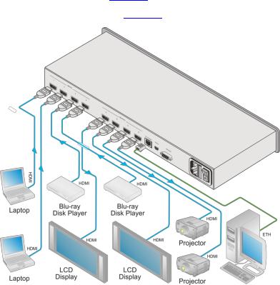
2.Connect the four HDMI OUTPUT connectors (from OUTPUT A to OUTPUT D) to up to four HDMI acceptors (for example, LCD displays and/or projectors).
3.Connect the power cord (not shown in Figure 3).
4.If required, connect:
A PC via RS-232, see Section 6.3
The ETHERNET port, see Section 6.4
Figure 3: Connecting the VSM-4x4HFS Presentation Switcher / Scaler
10 |
VSM-4x4HFS - Connecting and Operating the VSM-4x4HFS |
|
|

5.1.2Operating in the Matrix Mode
To select the inputs via the front panel buttons/IR remote control transmitter:
1.Select the Matrix operation mode.
2.Press an output and then an input to switch to the selected output.
You can also switch several inputs and outputs using the TAKE button (see Section 6.1.2).
5.2The Video Wall Mode
The video wall mode lets you display the output on a set of four monitors / projectors / TV sets that are tiled together in a 2x2 setting to form one large display. Each output shows one quarter of the image as shown in the example in Figure 4. In the video wall mode the audio of the selected input is routed to one of the outputs.
Figure 4: The VSM-4x4HFS Video Wall Operation Mode
5.2.1Connecting the VSM-4x4HFS in the Video Wall Operation Mode
To connect the video wall as illustrated in Figure 5, do the following:
1.Connect an HDMI source (for example, a Blu-ray disk player) to the INPUT 1 connector (you can connect up to four input connectors), not shown in Figure 5.
2.Connect the HDMI output connectors to the video wall screens. Connect the:
OUTPUT A connector to the top left screen
OUTPUT B connector to the top right screen
VSM-4x4HFS - Connecting and Operating the VSM-4x4HFS |
11 |
|
|
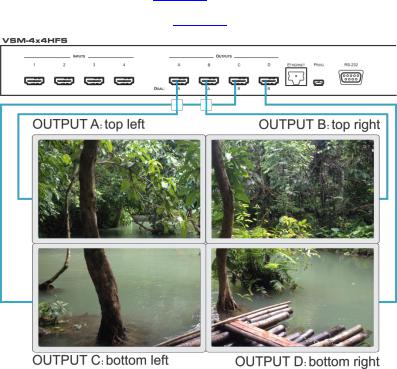
OUTPUT C connector to the bottom left screen
OUTPUT D connector to the bottom right screen
3.Connect the power cord (not shown in Figure 5).
4.If required, connect:
A PC via RS-232, see Section 6.3
The ETHERNET port, see Section 6.4
Figure 5: Connecting the VSM-4x4HFS in the Video Wall Operation Mode
5.2.2Operating in the Video Wall Mode
To select the inputs via the front panel buttons/IR remote control transmitter:
1.Select the Video Wall operation mode.
2.Press an input to switch to the output.
12 |
VSM-4x4HFS - Connecting and Operating the VSM-4x4HFS |
|
|
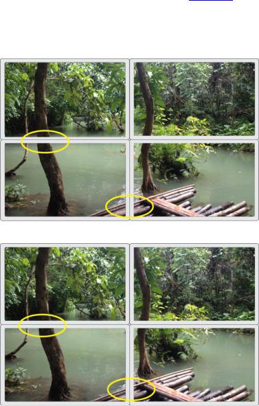
5.2.3Bezel Correction
You can use bezel correction via the OUTPUT menu (see Section 6.2.1) to make up for the rims around the displays used for creating the video wall, thus creating one smooth picture. In the example in Figure 6 the top photo shows the video wall before bezel connection and the lower photo shows the corrected image on the video wall.
Figure 6: VSM-4x4HFS Bezel Correction
VSM-4x4HFS - Connecting and Operating the VSM-4x4HFS |
13 |
|
|

5.3The Dual Mode
In the Dual operation mode the VSM-4x4HFS is set as a 4x2 switcher with picture-in- picture capabilities that outputs two identical A outputs and two identical B outputs (see Figure 7).
The dual outputs display any two selected input signals together on one screen. The OSD/IR remote control transmitter/Web pages lets you set the DUAL mode to the POP (side-by-side) or PIP (picture-in-picture) mode.
5.3.1Connecting the VSM-4x4HFS in the Dual Operation Mode
To connect in the Dual mode as illustrated in Figure 7, do the following:
1.Connect an HDMI source (for example, a Blu-ray disk player) to the INPUT 1 connector (from 1 to 4), not shown in Figure 7.
2.Connect the HDMI output connectors as follows. Connect the:
DUAL A connector to an HDMI acceptor (for example, an LCD display)
DUAL A connector to an HDMI acceptor (for example, an LCD display)
DUAL B connector to an HDMI acceptor (for example, an LCD display)
DUAL B connector to an HDMI acceptor (for example, an LCD display)
Note that you do not have to connect all the outputs.
3.Connect the power cord (not shown in Figure 7).
4.Setup the system (see Section 5.3)
5.If required, connect:
A PC via RS-232, see Section 6.3
The ETHERNET port, see Section 6.4
14 |
VSM-4x4HFS - Connecting and Operating the VSM-4x4HFS |
|
|
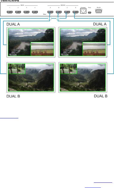
Figure 7: Connecting the VSM-4x4HFS in the Dual Operation Mode
Note that in this example “Show” is selected in the BORDER menu item (see
Section 6.2.1) to display all the borders.
5.3.2Operating in the Dual Mode
To select the inputs via the front panel buttons/IR remote control transmitter:
1.Select the DUAL operation mode.
2.Select one of the dual outputs (A: A or B; B: C or D).
3.Select any two inputs: the first selection would be the LEFT (POP mode) or the MAIN (PIP mode) image and the second would be the RIGHT (POP mode) or the PIP (PIP mode) image.
To select the inputs via the OSD, use the SOURCE menu item (see Section 6.2.1). To select the inputs via the IR remote control transmitter, see Section 6.6.
VSM-4x4HFS - Connecting and Operating the VSM-4x4HFS |
15 |
|
|
5.4The QUAD Mode
The QUAD view shows any four inputs on one screen (each quarter of a screen can show any selected input) and outputs it identically to all four outputs (OUTPUT A to OUTPUT D). Figure 8 shows the order in which the outputs are set in the QUAD mode (this order cannot be configured):
Figure 8: the VSM-4x4HFS QUAD Operation Mode Input Orientation
5.4.1Connecting the VSM-4x4HFS in the Quad Operation Mode
To connect the VSM-4x4HFS in the QUAD mode as illustrated in Figure 9, do the following:
1.Connect an HDMI source to up to four inputs (for example, a Blu-ray disk player) to the INPUT 1 connector (from 1 to 4), not shown in Figure 9.
2.Connect the HDMI output connectors OUTPUT A, OUTPUT B, OUTPUT C and OUTPUT D to an HDMI acceptor (for example, to LCD displays).
Note that you do not have to connect all the outputs
3.Connect the power cord (not shown in Figure 9).
4.If required, connect:
A PC via RS-232, see Section 6.3
The ETHERNET port, see Section 6.4
All four inputs are displayed on each output.
16 |
VSM-4x4HFS - Connecting and Operating the VSM-4x4HFS |
|
|
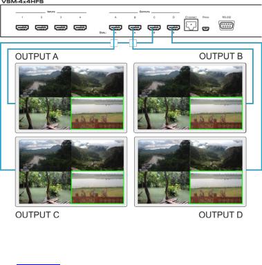
Figure 9: Connecting the VSM-4x4HFS in the Quad Operation Mode
Note that in this example “Only Selected” is selected in the BORDER menu item
(see Section 6.2.1) to display only the border of the selected output.
VSM-4x4HFS - Connecting and Operating the VSM-4x4HFS |
17 |
|
|

6 Controlling the VSM-4x4HFS
The VSM-4x4HFS can be controlled via:
The front panel buttons (see Section 6.1)
The OSD menu (see Section 6.2)
RS-232 serial commands transmitted by a touch screen system, PC, or other serial controller (see Section 6.3)
The ETHERNET (see Section 6.4), via the Web Pages
The infrared remote control transmitter (see Section 6.5)
6.1Controlling via the Front Panel Buttons
The VSM-4x4HFS includes the following front panel buttons:
Input selector buttons for selecting the required INPUT, HDMI (1 to 4) and OUTPUT/WINDOW selector buttons (A to D)
ALL (to connect a selected input to all the outputs) and OFF (to disconnect a selected output from the inputs) buttons
MODE buttons: MATRIX, VIDEO WALL, DUAL and QUAD
STO and RCL buttons
A TAKE button
An IDENTIFY button to identify the inputs connected to the outputs
MENU, ENTER, and up, down, left and right arrow buttons to for the OSD menu
RESET TO XGA/720p and PANEL LOCK buttons
18 |
VSM-4x4HFS - Controlling the VSM-4x4HFS |
|
|

6.1.1Switching Inputs to Outputs
The switching procedures are different for each of the four operation modes. Note that incomplete operations on the VSM-4x4HFS timeout after 15 seconds.
Matrix Mode
To switch an input to an output in the Matrix mode:
1.Press the required OUTPUT/WINDOW button. The selected button illuminates.
2.Press an INPUT button to select the input to switch to the output.
You can also switch several inputs and outputs using the TAKE button (see Section 6.1.2).
Video Wall Mode
To switch an input to the output, press an input button (from 1 to 4). The selected image appears on the video wall.
The audio input signal is routed to one of the four displays.
Dual Mode
POP Mode: select the inputs to switch to the LEFT and RIGHT images for each of the two dual groups (two A outputs and two B outputs).
PIP Mode: select the inputs to switch to the MAIN and PIP images for each of the two dual groups (two A outputs and two B outputs).
To select the images for group A (POP/PIP) using the front panel buttons:
1.Press OUTPUT A (or OUTPUT B). The selected button illuminates.
2.Press an INPUT button (from 1 to 4) to select the left/main image on the output.
3.Press an INPUT button (from 1 to 4) to select the right/PIP image on the output.
VSM-4x4HFS - Controlling the VSM-4x4HFS |
19 |
|
|
To select the images for group B (POP/PIP) using the front panel buttons:
1.Press OUTPUT C (or OUTPUT D). The selected button illuminates.
2.Press an INPUT button (from 1 to 4) to select the left/main image on the output.
3.Press an INPUT button (from 1 to 4) to select the right/PIP image on the output.
The audio signal of the input selected first (the left/main image) will be routed to the output.
QUAD Mode
In the QUAD mode there are no input/output switching operations since all the
inputs appear on each output in a preset order.
6.1.1.1Switching an Input to all Outputs
This feature is available for all operation modes except the video wall mode To switch an input to all the outputs:
1.Press the ALL button.
2.Press an INPUT button to select the input to switch to all outputs. The selected input is switched to all outputs.
6.1.1.2Disconnecting an Input from an Output
To disconnect an input from an output:
1.Press the required OUTPUT button. The selected output Illuminates.
2.Press the OFF button.
The selected output is disconnected.
20 |
VSM-4x4HFS - Controlling the VSM-4x4HFS |
|
|
6.1.1.3Disconnecting all the Inputs from the Outputs
This feature is available for all operation modes except the video wall mode. To disconnect all the inputs from the outputs:
1.Press the ALL button.
2.Press the OFF button.
All the inputs are disconnected from all the outputs.
6.1.2The TAKE Button
You can choose to work in the At Once or the Confirm mode. When the VSM-4x4HFS operates in the At Once mode, pressing an output-input combination implements the action immediately. In the Confirm mode, the TAKE button must be pressed to activate the switch.
The At Once Mode
In the At Once mode, execution is immediate and actions require no user confirmation. However, no protection is offered against changing an action in error.
The Confirm Mode
In the Confirm mode:
You can enter several actions and then confirm them by pressing the TAKE button to simultaneously activate the multiple switches
Every action requires user confirmation which protects against erroneous switching
Execution is delayed until the user confirms the action
Note that if the TAKE button is not pressed within 60 seconds, this action is aborted
VSM-4x4HFS - Controlling the VSM-4x4HFS |
21 |
|
|

6.1.2.1Toggling between the At Once and Confirm Modes
To toggle between the At Once and Confirm modes:
1.Press the TAKE button to toggle from the At Once mode (the TAKE button is not illuminated) to the Confirm mode (the TAKE button lights).
Actions now require user confirmation and the TAKE button lights.
2.Press the TAKE button to toggle from the Confirm mode back to the At Once mode.
Actions no longer require user confirmation and the TAKE button no longer lights.
6.1.2.2Confirming a Switching Action
To confirm a switching action (in the Confirm mode):
1.Press an output-input combination. The TAKE button flashes.
2.Press the flashing TAKE button to confirm the action. The TAKE button lights.
To confirm several switching actions (in the Confirm mode):
1.Press each OUTPUT-INPUT combination in sequence. The TAKE button flashes.
2.Press the flashing TAKE button to confirm all the actions. The TAKE button lights.
6.1.3Storing/Recalling In/Out Configurations
You can store and recall up to four input/output configuration setups per operation mode via the four INPUT buttons. The stored setups are saved in the non-volatile memory.
Note that you can also store and recall a setup via the OSD menu (see Section 6.2.1) and the Web pages (see Section 7).
22 |
VSM-4x4HFS - Controlling the VSM-4x4HFS |
|
|
6.1.3.1Storing an Input/Output Configuration
To store the current status in memory, do the following:
1.Press the STO button. The STO button lights.
2.Press one of the INPUT buttons (this will be the setup # in which the current status is stored). If in the Confirm mode, press the blinking TAKE button to confirm the action.
The memory stores the data at that reference.
6.1.3.2Recalling an In/Out Configuration
To recall an input/output configuration, do the following:
1.Press the RCL button. The RCL button lights.
2.Press the appropriate INPUT button (the button # corresponding to the setup #). If in the Confirm mode, that setup configuration will only be implemented after pressing the TAKE button.
The memory recalls the stored data from that reference.
6.1.4Front Panel Button Shortcuts
This section defines several front panel button shortcuts:
Selecting an audio source – press and hold (for 3 seconds) an output (OUTPUT A to OUTPUT D) to select the audio source
Muting the audio output – press and hold (for 3 seconds) the ALL button to toggle between muting (blocking out the sound) and enabling the audio output
Resetting the machine – press the MENU Button while plugging the power to reset the machine
VSM-4x4HFS - Controlling the VSM-4x4HFS |
23 |
|
|
Loading...