


 Loading...
KRAMER ELECTRONICS LTD.
USER MANUAL
MODEL:
SID-X1N
Step-in Commander
P/N: 2900-300302 Rev 5

Contents
1 |
Introduction |
1 |
2 |
Getting Started |
2 |
2.1 |
Achieving the Best Performance |
2 |
2.2 |
Safety Instructions |
2 |
2.3 |
About the Power Connect Plus™ Feature |
3 |
2.4 |
Shielded Twisted Pair/Unshielded Twisted Pair |
3 |
2.5 |
Recycling Kramer Products |
3 |
3 |
Overview |
4 |
4 |
Defining the SID-X1N Step-in Commander |
6 |
5 |
Connecting the SID-X1N |
8 |
5.1 |
Connecting the Remote Step-In Switch and LED |
9 |
5.2 |
Connecting the Remote Select Switch and LED |
10 |
5.3 |
Connecting the Remote Input Selection LEDs |
11 |
6 |
Principles of Operation |
12 |
6.1 |
Video Input Selection |
12 |
6.2 |
Audio Signal Control |
13 |
6.3 |
Automatic Output Shutdown |
13 |
7 |
Operating the SID-X1N |
14 |
7.1 |
Manually Selecting an Input |
14 |
7.2 |
Taking Control of the Switcher Input |
15 |
7.3 |
Locking the EDID |
15 |
7.4 |
Adjusting the UXGA Input Phase |
15 |
8 |
Configuring and Maintaining the SID-X1N |
16 |
8.1 |
Setting the Configuration DIP-switch |
16 |
9 |
Wiring the Twisted Pair RJ-45 Connectors |
18 |
10 |
Technical Specifications |
19 |
10.1 |
Supported Resolutions |
20 |
11 |
Default EDID |
22 |
11.1 |
HDMI, DisplayPort and DVI |
22 |
11.2 |
PC-UXGA |
24 |
12 |
Remote Commands |
26 |
12.1 |
Kramer Protocol 2000 Syntax |
26 |
12.2 |
Kramer Protocol 2000 Instruction Codes |
27 |
12.3 |
RS-232 Hardware Interface |
28 |
Figures
Figure 1: SID-X1N Step-in Commander Front Panel |
6 |
Figure 2: SID-X1N Step-in Commander Rear Panel |
7 |
Figure 3: Connecting the SID-X1N Step-in Commander |
8 |
Figure 4: Remote Step-In Switch and LED Wiring |
9 |
Figure 5: Remote Select Switch and LED Wiring |
10 |
Figure 6: Remote Input Indicator LED Connections |
11 |
Figure 7: Remote Input Indicator LED Wiring |
11 |
Figure 8: The Configuration DIP-switch |
16 |
Figure 9: TP Pinout Wiring |
18 |
|
|
SID-X1N – Contents |
i |
|
|

1 Introduction
Welcome to Kramer Electronics! Since 1981, Kramer Electronics has been providing a world of unique, creative, and affordable solutions to the vast range of problems that confront video, audio, presentation, and broadcasting professionals on a daily basis. In recent years, we have redesigned and upgraded most of our line, making the best even better!
Our 1,000-plus different models now appear in 14 groups that are clearly defined by function: GROUP 1: Distribution Amplifiers; GROUP 2: Switchers and Routers; GROUP 3: Control Systems; GROUP 4: Format/Standards Converters; GROUP 5: Range Extenders and Repeaters; GROUP 6: Specialty AV Products; GROUP 7:
Scan Converters and Scalers; GROUP 8: Cables and Connectors; GROUP 9: Room Connectivity; GROUP 10: Accessories and Rack Adapters and GROUP 11: Sierra Video Products; GROUP 12: Digital Signage; and GROUP 13: Audio, and GROUP 14: Collaboration.
Thank you for purchasing the Kramer MegaTOOLS® SID-X1N Step-in
Commander which is ideal for:
•Display systems requiring simple input selection
•Remote monitoring of computer activity in schools and businesses
•Rental/staging applications
•Multimedia and presentation source selection
SID-X1N - Introduction |
1 |

2 Getting Started
We recommend that you:
•Unpack the equipment carefully and save the original box and packaging materials for possible future shipment
•Review the contents of this user manual
Go to www.kramerav.com/downloads/SID-X1N to check for up-to-date
i user manuals, application programs, and to check if firmware upgrades are available (where appropriate).
2.1Achieving the Best Performance
To achieve the best performance:
•Use only good quality connection cables (we recommend Kramer highresolution, high-quality cables) to avoid interference, deterioration in signal quality due to poor matching, and elevated noise levels (often associated with low quality cables)
•Do not secure the cables in tight bundles or roll the slack into tight coils
•Avoid interference from neighboring electrical appliances that may adversely influence signal quality
•Position your Kramer SID-X1N away from moisture, excessive sunlight and dust
!This equipment is to be used only inside a building. It may only be connected to other equipment that is installed inside a building.
2.2Safety Instructions
!Caution: There are no operator serviceable parts inside the unit
Warning: Use only the Kramer Electronics input power wall adapter that is provided with the unit
Warning: Disconnect the power and unplug the unit from the wall before installing
2 |
SID-X1N - Getting Started |
2.3About the Power Connect Plus™ Feature
The Power Connect Plus™ feature means that only the SID-X1N needs to be connected to a power source when the SID-X1N and receiver are within 60m (197ft) of each other. The Power Connect Plus™ feature applies as long as the cable can carry power and the distance does not exceed 60m on standard TP cable. (Heavier gauge cable may be used to extend the Power Connect Plus™ range).
2.4Shielded Twisted Pair/Unshielded Twisted Pair
Kramer engineers have developed special twisted pair cables to best match our digital twisted pair products; the Kramer BC-DGKat623 (CAT 6 23 AWG cable), and the Kramer BC-DGKat7a23 (CAT 7a 23 AWG cable). These specially built cables significantly outperform regular CAT 6 and CAT 7a cables.
2.5Recycling Kramer Products
The Waste Electrical and Electronic Equipment (WEEE) Directive 2002/96/EC aims to reduce the amount of WEEE sent for disposal to landfill or incineration by requiring it to be collected and recycled. To comply with the WEEE Directive, Kramer Electronics has made arrangements with the European Advanced Recycling Network (EARN) and will cover any costs of treatment, recycling and recovery of waste Kramer Electronics branded equipment on arrival at the EARN facility. For details of Kramer’s recycling arrangements in your particular country go to our recycling pages at www.kramerav.com/support/recycling/.
SID-X1N - Getting Started |
3 |

3 Overview
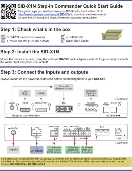
The SID-X1N accepts an HDMI, DisplayPort, DVI and PC graphics video input, as well as an unbalanced stereo audio input (which is embedded into the output signal), and transmits the signal via TP (Twisted Pair) cable to a compatible switcher or DGKat receiver, (for example, the VP-81SIDN or PT-572+).
The SID-X1N also provides an unbalanced, stereo audio output. When the SID-X1N is connected to a switcher, it also controls the input and output selection of the switcher.
In particular the SID-X1N: features:
•HDTV support
•HDMI with x.v.Color™ and 3D
•HDCP compliancy—works with sources that support HDCP repeater mode
Note: When using a MacBook as a source and the content is protected using HDCP, if the display does not support HDCP, no video is transmitted
•Input signal detection based on video clock presence
•Automatic input selection based on manual selection or last connected input
•Automatic analog audio detection and embedding
•Automatic output shutdown when the input signal is lost (with a configurable delay)
•Installation up to 50m (164ft) from the switcher, (30m with the TP-574)
•I-EDIDPro™ Kramer Intelligent EDID Processing™ – Intelligent EDID handling & processing algorithm ensures Plug and Play operation for HDMI systems
•A lockable EDID
•VGA phase adjustment
4 |
SID-X1N - Overview |
•PowerConnectPlus – A single connection to the receiver powers both units. The higher voltage PowerConnectPlus also powers regular PowerConnect devices via auto-negotiation
•Equalization and reclocking of the data
•A maximum data rate of 4.95Gbps (1.65Gb per graphics channel)
•Support for digital audio formats
•A MegaTOOLS® sized enclosure. Two devices can be mounted in a rack using the optional RK-T2B adapter
You can control the SID-X1N using the front panel buttons or remotely via contact closure switches.
SID-X1N - Overview |
5 |

4 Defining the SID-X1N Step-in Commander
Figure 1 defines the front panel of the SID-X1N.
|
Figure 1: SID-X1N Step-in Commander Front Panel |
||||
|
|
|
|
|
|
# |
Feature |
|
|
Function |
|
1 |
AUDIO IN 3.5mm Mini Jack |
|
Connect to an unbalanced stereo audio source |
||
2 |
HDMI |
LED |
|
Lights green when the HDMI input is selected |
|
3 |
HDMI Connector |
|
Connect to an HDMI source |
||
|
|
||||
4 |
DisplayPort |
LED |
|
Lights green when the DisplayPort input is selected |
|
5 |
DP Connector |
|
Connect to a DisplayPort source |
||
|
|
||||
6 |
DVI |
LED |
Lights green when the DVI input is selected |
||
7 |
DVI Connector |
|
Connect to a DVI source |
||
|
|
||||
8 |
|
LED |
|
Lights green when the PC-UXGA input is selected |
|
9 |
PC-UXGA |
PC-UXGA |
|
Connect to a PC graphics source |
|
|
15-pin HD |
|
|
|
|
|
|
|
|
|
|
|
|
Connector (F) |
|
|
|
10 |
INPUT SELECT Button |
|
Press repeatedly to cycle through the inputs manually to |
||
|
|
|
|
select an input, (overrides automatic selection, see |
|
|
|
|
|
Section 7.1). |
|
|
|
|
|
|
|
|
|
|
|
Note: When the button is lit it is inactive and pressing the |
|
|
|
|
|
button will not activate the input |
|
11 |
STEP-IN Button |
|
Press to activate the input on the switcher that the |
||
|
|
|
|
SID-X1N is connected to, (see Section 7.2) |
|
12 |
ON LED |
|
|
Lights green when the device is powered on |
|
6 |
SID-X1N - Defining the SID-X1N Step-in Commander |
Figure 2 defines the rear panel of the SID-X1N.
|
Figure 2: SID-X1N Step-in Commander Rear Panel |
||||
|
|
|
|
|
|
# |
Feature |
|
|
Function |
|
1 |
AUDIO OUT 3.5mm Mini Jack |
Connect to an unbalanced, stereo audio acceptor, (see |
|||
|
|
|
|
Section 4) |
|
2 |
TP OUT RJ-45 Connector |
Connect to a compatible switcher or DGKat receiver, (for |
|||
|
|
|
|
example, VP-81SIDN or PT-572+) using CAT 6 or higher |
|
|
|
|
|
specification cable |
|
3 |
REMOTE STEP-IN |
LED |
Connect to the anode of the remote Step-In LED indicator |
||
4 |
3-pin Terminal |
|
Switch |
Connect to the remote, Step-In switch, (see Section 5.1) |
|
Block |
|
||||
|
|
|
|
||
5 |
PROG RS-232 3-pin Terminal |
Connect to the PC via RS-232 to perform a firmware upgrade |
|||
|
Block |
|
|
|
|
6 |
|
LED |
Connect to the anode of the remote Input Select LED indicator, |
||
|
REMOTE |
|
|
(see Section 4) |
|
7 |
Switch |
Connect to the remote, Input Select switch, (see Section 5.2) |
|||
SELECT 8-pin |
|||||
8 |
LED HDMI, |
Connect to the anodes of the remote input indicators |
|||
Terminal Block |
|||||
|
|
DP, DVI |
(see Section 5.3) |
||
|
|
and UXGA |
|
||
9 |
OPTION 8x DIP-switch |
Sets the device behavior, (see Section 8.1) |
|||
10 |
12V DC Power Connector |
Connect to the supplied power adapter, center pin positive |
|||
SID-X1N - Defining the SID-X1N Step-in Commander |
7 |
Loading...