


 Loading...
» User’s Guide «
KISS 2U V2
KISS 2U V2 KTQ87-A
KISS 2U V2 PCI762-A
User's Guide (Version 1.00) 1056-7538
www.kontron.com

This page is intentionally left blank.
www.kontron.com

1. Table of Contents |
KISS 2U V2 MB_SBC– User's Guide (Version 1.00) |
|
1. Table of Contents |
|
|
1. Table of Contents ..................................................................................................................................... |
|
1 |
1.1. Table of Figures...................................................................................................................................... |
|
3 |
2. Introduction ........................................................................................................................................... |
|
5 |
2.1. Symbols used in this Manual..................................................................................................................... |
|
6 |
3. Important Instructions............................................................................................................................. |
|
7 |
3.1. Warranty Note ....................................................................................................................................... |
|
7 |
3.2. Exclusion of Accident Liability Obligation.................................................................................................... |
|
7 |
3.3. Liability Limitation / Exemption from the Warranty Obligation ........................................................................ |
|
7 |
4. General Safety Instruction for IT Equipment ................................................................................................ |
|
8 |
4.1. Operation of Laser Source Devices ............................................................................................................. |
|
9 |
4.2. Electrostatic Discharge (ESD) .................................................................................................................. |
|
10 |
4.2.1. Grounding Methods......................................................................................................................... |
|
10 |
4.3. Instructions for the Lithium Battery.......................................................................................................... |
|
10 |
5. Electromagnetic Compatibility (Class A Device) .......................................................................................... |
|
11 |
5.1. Electromagnetic Compatibility (EU) .......................................................................................................... |
|
11 |
5.2. FCC Statement (USA).............................................................................................................................. |
|
11 |
5.3. EMC Compliance (Canada) ....................................................................................................................... |
|
11 |
6. Scope of Delivery .................................................................................................................................... |
|
12 |
6.1. Type Label and Product Identification ....................................................................................................... |
|
12 |
7. Product Description ................................................................................................................................ |
|
13 |
7.1. Front Side ............................................................................................................................................ |
|
15 |
7.1.1. Power Button................................................................................................................................. |
|
16 |
7.1.2. LED Indicators................................................................................................................................ |
|
17 |
7.1.3. Ports on the Front Side .................................................................................................................... |
|
17 |
7.1.4. Front Access Panel .......................................................................................................................... |
|
17 |
7.1.5. Cover fastening screw on the front side ............................................................................................... |
|
18 |
7.1.6. Filter Mat and Filter Mat Holder ......................................................................................................... |
|
18 |
7.1.7. Fan Slide-in Module ........................................................................................................................ |
|
18 |
7.1.8. Drive Bays ..................................................................................................................................... |
|
18 |
7.2. Rear Side ............................................................................................................................................. |
|
19 |
7.2.1. System Configurations with SBC Card.................................................................................................. |
|
19 |
7.2.2. System Configuration with Motherboard ............................................................................................. |
|
20 |
7.2.3. System Configuration with Motherboard and Low Profile Cards ................................................................ |
20 |
|
7.2.4. Power Supply and ON/OFF Switch of the PSU ........................................................................................ |
|
22 |
7.2.5. Grounding Stud .............................................................................................................................. |
|
23 |
7.2.6. Fan Slide-In Module and Temperature Sensor ....................................................................................... |
|
23 |
7.3. Side View ............................................................................................................................................. |
|
23 |
7.4. Installed Motherboard / SBC Card............................................................................................................. |
|
24 |
7.5. System Configurations with SBC ............................................................................................................... |
|
24 |
7.6. System Configuration with Motherboard .................................................................................................... |
|
25 |
7.6.1. Riser Card and/or Backplane and available Bays.................................................................................... |
|
27 |
8. Installation and Removal ......................................................................................................................... |
|
28 |
8.1. Attaching the Rubber Feet ...................................................................................................................... |
|
28 |
www.kontron.com |
1 |

1. Table of Contents |
KISS 2U V2_MB_SBC – User's Guide (Version 1.00) |
8.2. Cover.................................................................................................................................................. |
29 |
8.3. Accessing Internal Components............................................................................................................... |
30 |
8.3.1. Installing /Removing Expansion Cards ............................................................................................... |
30 |
8.4. Installation in a 19" Industrial Cabinet ..................................................................................................... |
33 |
9. Starting Up............................................................................................................................................ |
34 |
9.1. AC Power Connection............................................................................................................................. |
34 |
9.2. Operating System and Hardware Components Drivers................................................................................... |
35 |
10. Maintenance and Prevention.................................................................................................................. |
36 |
10.1. Replacing System Fans ......................................................................................................................... |
36 |
10.2. Cleaning the Filter Mat ......................................................................................................................... |
38 |
10.3. Replacing the Lithium Battery ............................................................................................................... |
40 |
11. Slide Rails (Option) .............................................................................................................................. |
41 |
12. Technical Data...................................................................................................................................... |
42 |
12.1. Electrical Specifications ....................................................................................................................... |
43 |
12.2. Mechanical Specifications..................................................................................................................... |
43 |
12.3. Environmental Specifications ................................................................................................................ |
43 |
12.4. Directives and Standards ...................................................................................................................... |
44 |
13. Standard Interfaces – Pin Assignments ................................................................................................... |
45 |
13.1.1. Serial Interface (RS232) ................................................................................................................ |
45 |
13.1.2. VGA Port ..................................................................................................................................... |
45 |
13.1.3. USB Port ..................................................................................................................................... |
46 |
14. Technical Support................................................................................................................................. |
47 |
14.1. Returning Defective Merchandise ........................................................................................................... |
47 |
2 |
www.kontron.com |

1. Table of Contents |
KISS 2U V2 MB_SBC– User's Guide (Version 1.00) |
1.1. Table of Figures |
|
Fig. 1: Laser radiation warning label ................................................................................................................ |
9 |
Fig. 2: Rackmount version with closed access panel........................................................................................... |
13 |
Fig. 3: Desktop version with closed access panel............................................................................................... |
13 |
Fig. 4: Rackmount version with opened access panel ......................................................................................... |
13 |
Fig. 5: Desktop version with opened access panel ............................................................................................. |
13 |
Fig. 6: KISS 2U V2 platform........................................................................................................................... |
14 |
Fig. 7: Front (rackmount version) with the front access panel closed .................................................................... |
15 |
Fig. 8: 19” bracket with fixing screws.............................................................................................................. |
15 |
Fig. 9: Front (rackmount version) with the front access panel open ...................................................................... |
16 |
Fig. 10: Power button on the front ................................................................................................................. |
16 |
Fig. 11: LED indicators................................................................................................................................. |
17 |
Fig. 12: USB ports on the front side................................................................................................................ |
17 |
Fig. 13: Rear side of the KISS 2U V2 with an SBC card (shown with a PCI-762 and an AC wide rage PSU) ....................... |
19 |
Fig. 14: External ports of PCI-762 SBC card ...................................................................................................... |
19 |
Fig. 15: Rear side of the KISS 2U V2 with a KTQ87/Flex (here with a wide range power supply)................................... |
20 |
Fig. 16: Rear side of the KISS 2U V2 with a KTQ87/Flex (shown as a configuration for low profile expansion cards) ........ |
20 |
Fig. 17: External ports of the KTQ87/Flex motherboard ...................................................................................... |
21 |
Fig. 18: Detail: AC Wide Rang PSU .................................................................................................................. |
22 |
Fig. 19: Grounding stud marked with “Earth”symbol......................................................................................... |
23 |
Fig. 20: KISS 2U V2 - side view ...................................................................................................................... |
23 |
Fig. 21: Example of KISS 2U V2 Configuration with SBC (Single Board Computer) .................................................... |
24 |
Fig. 22: Example of KISS 2U V2 - Configuration with motherboard........................................................................ |
25 |
Fig. 23: Example of KISS 2U V2 - Configuration with motherboard (shown as config. for low-profile expansion cards).... |
26 |
Fig. 24: Inside of the cover with fixing brackets................................................................................................ |
29 |
Fig. 25: Loosen the cover fastening knurled screw on the front side ..................................................................... |
30 |
Fig. 26: Loosen the knurled screw on the rear side ............................................................................................ |
30 |
Fig. 27: This movment allow you to remove the centring and fixing bracket of the cover from the retaining plate of the |
|
chassis ............................................................................................................................................... |
31 |
Fig. 28: Removing the cover ......................................................................................................................... |
31 |
Fig. 29: Pulled-out card cage for configurations with SBC and motherboard, but not for configurations with motherboard |
|
for low profile cards (shownas a KISS 2U V2 system configuration with SBC) .................................................... |
31 |
Fig. 30: Detail: removing the fan slide-in module.............................................................................................. |
36 |
Fig. 31: Detail: Fan compartment (without fan slide-in module) .......................................................................... |
36 |
Fig. 32: Fan slide-in module without filtermat holder ........................................................................................ |
37 |
Fig. 33:Rear view of the fan slide-in module..................................................................................................... |
37 |
www.kontron.com |
3 |

1. Table of Contents |
KISS 2U V2_MB_SBC – User's Guide (Version 1.00) |
|
Fig. 34: Fan slide-in module with mounted filter mat holder................................................................................ |
|
37 |
Fig. 35: Side view of the fan slide-in module..................................................................................................... |
|
37 |
Fig. 36: Detail with filter mat holder on the fron side of the KISS 2U V2 platform ..................................................... |
38 |
|
Fig. 37: Detail without filter mat holder on the front side.................................................................................... |
|
39 |
Fig. 38: Filter mat holder without filter mat...................................................................................................... |
|
39 |
Fig. 39: Filtermatholder with filter mat............................................................................................................ |
|
39 |
Fig. 40: Filter mat ....................................................................................................................................... |
|
39 |
Fig. 41: Attached inner part of the slide rail (shown left side view of the KISS 2U V2 system) ..................................... |
41 |
|
Fig. 42: KISS 2U V2 platform with slide rail in pulled-out position ........................................................................ |
|
41 |
Fig. 43: KISS 2U V2 platform with slide rail in pushed-in position ......................................................................... |
|
41 |
4 |
www.kontron.com |

2. Introduction |
KISS 2U V2 MB_SBC– User's Guide (Version 1.00) |
2. Introduction
Kontron Europe GmbH would like to point out that the information contained in this manual may be subject to technical alteration, particularly as a result of the constant upgrading of Kontron Europe products. The attached documentation does not entail any guarantee on the part of Kontron Europe with respect to technical processes described in the manual or any product characteristics set out in the manual. Kontron Europe does not accept any liability for any printing errors or other inaccuracies in the manual unless it can be proven that Kontron Europe is aware of such errors or inaccuracies or that Kontron Europe is unaware of these as a result of gross negligence and Kontron Europe has failed to eliminate these errors or inaccuracies for this reason. Kontron Europe expressly informs the user that this manual only contains a general description of technical processes and instructions which may not be applicable in every individual case. In cases of doubt, please contact Kontron Europe.
This manual is protected by copyright. All rights are reserved by Kontron Europe. Copies of all or part of this manual or translations into a different language may only be made with the prior written consent of Kontron Europe. Kontron Europe points out that the information contained in this manual is constantly being updated in line with the technical alterations and improvements made by Kontron Europe to the products and thus this manual only reflects the technical status of the products by Kontron Europe at the time of printing.
© 2014 by Kontron Europe GmbH
Printing and duplication, even of sections, is only permissible with the express approval of
Kontron Europe GmbH
Lise-Meitner-Str. 3-5
86156 Augsburg
Germany
www.kontron.com |
5 |
2. Introduction |
KISS 2U V2_MB_SBC – User's Guide (Version 1.00) |
2.1. Symbols used in this Manual
Symbol Meaning
This symbol indicates the danger of injury to the user or the risk of damage to the product if the corresponding warning notices are not observed.
This symbol indicates that the product or parts thereof may be damaged if the corresponding warning notices are not observed.
This symbol indicates general information about the product and the user manual.
This symbol indicates detail information about the specific product configuration.
This symbol precedes helpful hints and tips for daily use.
This symbol indicates that the system is equipped with hazardous moving parts.
There is danger of injury to the user or the risk of damage to the product if the corresponding warning notices are not observed.
Before maintenance and repair activities, the device must be disconnected from the power supply.
6 |
www.kontron.com |

3. Important Instructions |
KISS 2U V2 MB_SBC– User's Guide (Version 1.00) |
3. Important Instructions
This manual provides important information required for the proper operation of the KISS 2U V2 platform!
This chapter contains instructions which must be observed when working with the KISS 2U V2 platform.
3.1. Warranty Note
Due to their limited service life, parts which by their nature are subject to a particularly high degree of wear (wearing parts) are excluded from the warranty beyond that provided by law. This applies to batteries, for example.
3.2. Exclusion of Accident Liability Obligation
Kontron Europe shall be exempted from the statutory accident liability obligation if the user fails to observe the included document: “General Safety Instructions for IT Equipment” the hints in this manual or eventually the warning signs label on the device.
3.3. Liability Limitation / Exemption from the Warranty Obligation
In the event of damage to the device caused by failure to observe the included document “General Safety Instructions for IT Equipment”, the hints in this manual or eventually the warning signs label on the device, Kontron Europe shall not be required to honor the warranty even during the warranty period and shall be exempted from the statutory accident liability obligation.
www.kontron.com |
7 |

4. General Safety Instruction for IT Equipment |
KISS 2U V2_MB_SBC – User's Guide (Version 1.00) |
4. General Safety Instruction for IT Equipment
Please read this chapter carefully and take careful note of the instructions, which have been compiled for your safety and to ensure to apply in accordance with intended regulations. If the following general safety instructions are not observed, it could lead to injuries to the operator and/or damage of the product; in cases of nonobservance of the instructions Kontron is exempt from accident liability, this also applies during the warranty period.
The product has been built and tested according to the basic safety requirements for low voltage (LVD) applications and has left the manufacturer in safety-related, flawless condition. To maintain this condition and to also ensure safe operation, the operator must not only observe the correct operating conditions for the product but also the following general safety instructions:
The product must be used as specified in the product documentation, in which the instructions for safety for the product and for the operator are described. These contain guidelines for setting up, installation and assembly, maintenance, transport or storage.
The on-site electrical installation must meet the requirements of the country's specific local regulations.
If a power cable comes with the product, only this cable should be used. Do not use an extension cable to connect the product.
To guarantee that sufficient air circulation is available to cool the product, please ensure that the ventilation openings are not covered or blocked. If a filter mat is provided, this should be cleaned regularly. Do not place the system close to heat sources or damp places. Make sure the system is well ventilated.
Only devices or parts which fulfill the requirements of SELV circuits (Safety Extra Low Voltage) as stipulated by IEC 60950-1 may be connected to the available interfaces.
Before opening the device, make sure that the device is disconnected from the mains.
Switching off the device by its power button does not disconnect it from the mains. Complete disconnection is only possible if the power cable is removed from the wall plug or from the device. Ensure that there is free and easy access to enable disconnection.
The device may only be opened for the insertion or removal of add-on cards (depending on the configuration of the system). This may only be carried out by qualified operators.
If extensions are being carried out, the following must be observed:
•all effective legal regulations and all technical data are adhered to
•the power consumption of any add-on card does not exceed the specified limitations
•the current consumption of the system does not exceed the value stated on the product label.
Only original accessories that have been approved by Kontron can be used.
Please note: safe operation is no longer possible when any of the following applies:
•the device has visible damages or
•the device is no longer functioning
In this case the device must be switched off and it must be ensured that the device can no longer be operated.
8 |
www.kontron.com |
4. General Safety Instruction for IT Equipment |
KISS 2U V2 MB_SBC– User's Guide (Version 1.00) |
Additional safety instructions for DC power supply circuits
To guarantee safe operation of devices with DC power supply voltages larger than 60 volts DC or a power consumption larger than 240 VA, please observe that:
•the device is set up, installed and operated in a room or enclosure marked with “RESTRICTED ACCESS”, if there are no safety messages on product as safety signs and labels on the device itself.
•no cables or parts without insulation in electrical circuits with dangerous voltage or power should be touched directly or indirectly
•a reliable protective earthing connection is provided
•a suitable, easily accessible disconnecting device is used in the application (e.g. overcurrent protective device), if the device itself is not disconnectable
•a disconnect device, if provided in or as part of the equipment, shall disconnect both poles simultaneously
•interconnecting power circuits of different devices cause no electrical hazards
A sufficient dimensioning of the power cable wires must be selected – according to the maximum electrical specifications on the product label – as stipulated by EN60950-1 or VDE0100 or EN60204 or UL508 regulations.
The devices do not generally fulfill the requirements for "centralized DC power systems“ (UL 60950-1, Annex NAB; D2) and therefore may not be connected to such devices!
Caution:
Energy hazards >240 VA are present inside the chassis!
Activities such as system expansion with expansion cards, or maintanance have to be carried-out by qualified personnel familiar with the associated dangers!
The installation instructions for the KISS 2U V2 Platform is the responsibility of the distributor.
When used as intended the KISS 2U V2 platform is to operate only closed and locked.
Only when the cover is properly installed, secured with the knurled screws on the rear and the cover fastening screw on the front, and the access panel is locked with the key, it is ensured that the user doesn’t have access to the internal parts of the KISS 2U V2 platform, loaded with hazardous energy.
4.1. Operation of Laser Source Devices
Fig. 1: Laser radiation warning label
The optional CD ROM and DVD drives contain light-emitting diodes (classified in accordance with IEC 60825-1:2007: LASER CLASS 1) and therefore must not be opened.
If the enclosure of such a drive is opened, invisible laser radiation is emitted. Do not allow yourself to be exposed to this radiation.
The laser system meets the code of Federal Regulations 21 CFR, 1040 for the USA and the Canadian Radiation Emitting Devices Act, REDR C 1370.
www.kontron.com |
9 |
4. General Safety Instruction for IT Equipment |
KISS 2U V2_MB_SBC – User's Guide (Version 1.00) |
4.2. Electrostatic Discharge (ESD)
A sudden discharge of electrostatic electricity can destroy static-sensitive devices or micro-circuitry. Proper packaging and grounding techniques are necessary precautions to prevent damage. Always take the following precautions:
1.Transport boards in static-safe containers such as boxes or bags.
2.Keep electrostatic sensitive parts in their containers until they arrive at the ESD-safe workplace.
3.Always be properly grounded when touching a sensitive board, component, or assembly.
4.Store electrostatic-sensitive boards in protective packaging or on antistatic mats.
4.2.1. Grounding Methods
The following measures help to avoid electrostatic damages to the device:
1.Cover workstations with approved antistatic material. Always wear a wrist strap connected to workplace as well as properly grounded tools and equipment.
2.Use anti-static mats, heel straps, or air ionizes to give added protection.
3.Always handle electrostatic sensitive components by their edge or by their casing.
4.Avoid contact with pins, leads, or circuitry.
5.Turn off power and input signals before inserting and removing connectors or connecting test equipment.
6.Keep work area free of non-conductive materials such as ordinary plastic assembly aids and styrofoam.
7.Use field service tools such as cutters, screwdrivers, and vacuum cleaners which are conductive.
8.Always place drives and boards PCB-assembly-side down on the foam.
4.3. Instructions for the Lithium Battery
The installed CPU board is equipped with a Lithium battery. When replacing the lithium battery, please follow the corresponding instructions in the section 10.3 “Replacing the Lithium Battery”.
Caution
Danger of explosion when replacing with wrong type of battery. Replace only with the same or equivalent type recommended by the manufacturer. The lithium battery type must be UL recognized.
Do not dispose of lithium batteries in general trash collection. Dispose of the battery according to the local regulations dealing with the disposal of these special materials, (e.g. to the collecting points for dispose of batteries).
10 |
www.kontron.com |

5. Electromagnetic Compatibility (Class A Device) |
KISS 2U V2 MB_SBC– User's Guide (Version 1.00) |
5. Electromagnetic Compatibility (Class A Device)
5.1. Electromagnetic Compatibility (EU)
This product is intended only for use in industrial areas. The most recent version of the EMC guidelines (EMC Directive 2004/108/EC) and/or the German EMC laws apply. If the user modifies and/or adds to the equipment (e.g. installation of add-on cards) the prerequisites for the CE conformity declaration (safety requirements) may no longer apply.
Warning!
This is a class A product. In domestic environment this product may cause radio interference in which case the user may be required to take adequate measures.
5.2. FCC Statement (USA)
This equipment has been tested and found to comply with the limits for a Class A digital device, pursuant to Part 15 of the FCC Rules. These limits are designed to provide reasonable protection against harmful interference when the equipment is operated in commercial environment. This equipment generates, uses, and can radiate radio frequency energy and, if not installed and used in accordance with the instruction manual, may cause harmful interference to radio communications.
Operation of this equipment in residential area is likely to cause harmful interference in which case the user will be required to correct the interference at his own expense.
5.3. EMC Compliance (Canada)
The method of compliance is self-declaration to Canadian standard ICES-003:
(English): This Class A digital apparatus complies with the Canadian ICES-003.
(French): Cet appareil numérique de la class A est conforme à la norme NMB-003 du Canada.
www.kontron.com |
11 |

6. Scope of Delivery |
KISS 2U V2_MB_SBC – User's Guide (Version 1.00) |
6. Scope of Delivery
KISS 2U V2 platform (system configuration ordered)
2x key for the front access panel lock
1x AC power cable (for AC system configuration)
2x AC power cable (for AC system configuration with redundant PSU)
Rubber feet (self-adhesive)
General Safety Instruction for IT Equipment
Optional Parts
Slide Rails (PN: 1016-5807)
Rack Slide Rails Kit for KISS 1U and KISS 2U/4U V2 (PN: 1051-7200)
6.1.Type Label and Product Identification
The type label (product designation, serial number) and the inspection status label of your KISS 2U V2 platform are located on the right side of the device.
System Type |
Product Name |
Product Identifikation |
|
|
|
KISS 2U V2 |
KISS 2U V2 xxxxxxxx-y |
KISS 2U V2 = System Type |
|
|
The “xxxxxxxxx” group is replaced by up to a max. 8-digit combination of |
|
|
numbers, letter or space, and represents the installed CPU board |
|
|
The “y” is replaced by a single letter (A through Z) representing the power |
|
|
supply installed into the system. |
|
|
|
Note:
A: corresponds to the systems with a wide range AC power supply
12 |
www.kontron.com |
7. Product Description |
KISS 2U V2 MB_SBC– User's Guide (Version 1.00) |
7. Product Description
The KISS 2U V2 platform expands the Kontron KISS computer line. KISS 2U V2 is a scalable 2U (19") platform, equipped with a motherboard (KTQ 87/Flex) or a SBC (PCI-762) (Single Board Computer) board, supporting various system configurations
(refer to “KISS 2U V2 Systems - Configuration Guides” on our website). The flexible customer-specific hardware system configuration and the robust construction with excellent mechanical stability of the KISS 2U V2 platform offer the superior qualities of a computer designed for operation in harsh industrial environment.
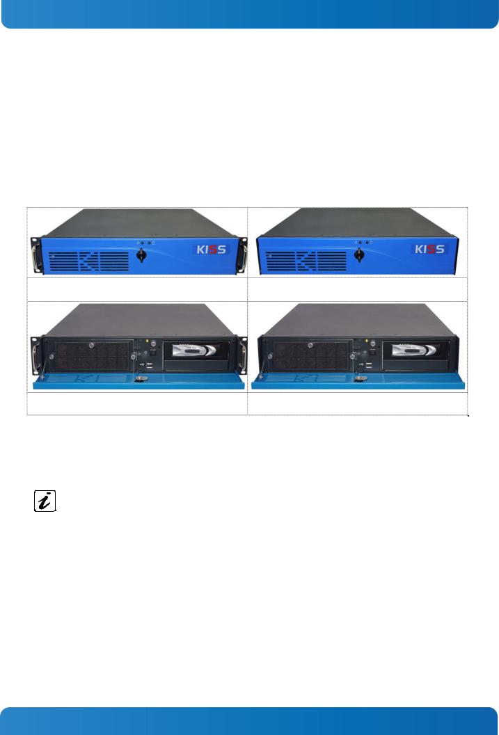
The KISS 2U V2 platform is designed to be installed in 19" racks. It may be also installed as a desktop unit.
Versions of the KISS 2U V2 platform:
Fig. 2: Rackmount version with closed access panel
Fig. 4: Rackmount version with opened access panel
Fig. 3: Desktop version with closed access panel
Fig. 5: Desktop version with opened access panel
The system can be equipped with up to two drive bays (depending on the system configuration):
L1: one 5:25" front accessible drive bay
L2: one 3.5" internal drive bay or an front accessible slim drive
For customized versions and system configurations, please observe the corresponding “KISS 2U V2 System - Configuration Guides” for KISS 2U V2 on our web site www.kontron.com.
The device is equipped with an AC wide rang.
The controls of the KISS 2U V2 platform are located behind the front access panel and consist, as standard, of a power button, a power and HDD LED.
Two system fans are installed at the front side of the unit. These are attached to the system by a fan slide-in module. The fan slide-in module simplifies the installation and removal of these components.
The washable filter mat, which protects your system against dust and dirt, is located on the front side of the system. This filter mat can be replaced during operation.
Depending on the integrated CPU board [motherboard or SBC (Single Board Computer)] your system can be expanded with different expansion cards.
The type label is located on the right hand side of the device.
www.kontron.com |
13 |
Loading...