


 Loading...
with small cooler
MSM800BEV
Document Revision 100
If it's embedded, it's Kontron.

» Table of Contents «
1 |
User Information............................................................................ |
6 |
1.1 |
About this Document ............................................................................................................... |
6 |
1.2 |
Copyright Notice ..................................................................................................................... |
6 |
1.3 |
Trademarks ............................................................................................................................ |
6 |
1.4 |
Standards.............................................................................................................................. |
6 |
1.5 |
Warranty ............................................................................................................................... |
6 |
1.6 |
Technical Support ................................................................................................................... |
7 |
1.7 |
Environmental Protection Statement ........................................................................................... |
7 |
1.8 |
RoHS Commitment .................................................................................................................. |
7 |
1.8.1 RoHS Compatible Product Design............................................................................................... |
8 |
|
1.8.2 RoHS Compliant Production Process ........................................................................................... |
8 |
|
1.8.3 |
WEEE Application ................................................................................................................... |
8 |
1.9 |
Swiss Quality .......................................................................................................................... |
8 |
1.10 |
The Swiss Association for Quality and Management Systems.............................................................. |
9 |
2 |
Introduction ................................................................................ |
10 |
2.1 |
MSM800BEV Ordering Information ............................................................................................ |
10 |
2.2 |
MSM800BEV Applications........................................................................................................ |
10 |
2.3 |
MSM800BEV Features ............................................................................................................. |
11 |
2.3.1 |
The MSM800BEV Model.......................................................................................................... |
11 |
2.4 |
Block Diagram ...................................................................................................................... |
12 |
2.4.1 |
MSM800BEV........................................................................................................................ |
12 |
2.5 |
MICROSPACE® Documentation .................................................................................................. |
12 |
2.6 |
Product Photo ...................................................................................................................... |
13 |
2.6.1 |
MSM800BEV........................................................................................................................ |
13 |
3 |
Specifications............................................................................... |
14 |
4 |
Quick Start Guide........................................................................... |
17 |
4.1 |
Print Manuals from the Product CD ............................................................................................ |
17 |
4.2 |
The MSM800CON, Part Nr. 803036 ............................................................................................. |
17 |
4.3 |
The LANCON, Part Nr. 803046................................................................................................... |
18 |
www.kontron.com

4.4 |
The DVICON, Part Nr. 803042 ................................................................................................... |
19 |
4.5 |
Connect Peripherals to the Board.............................................................................................. |
20 |
4.6 |
The Development Kit, Part Nr. 802118........................................................................................ |
21 |
4.7 |
Power Up the Board ............................................................................................................... |
22 |
4.8 |
BIOS Setup .......................................................................................................................... |
25 |
4.9 |
Boot Up the Operating System and Install the Drivers.................................................................... |
25 |
5 |
Connectors & Jumpers .................................................................... |
26 |
5.1 |
Connectors .......................................................................................................................... |
26 |
5.1.1 |
Top Side of the MSM800BEV V2.1 ............................................................................................. |
27 |
5.1.2 |
Bottom Side of the MSM800BEV V2.1........................................................................................ |
28 |
5.1.3 |
X1 Power Supply .................................................................................................................. |
29 |
5.1.4 |
X10 VGA Monitor (CRT-signals)................................................................................................ |
29 |
5.1.5 |
X15 LCD TFT Interface (flat panel signals) .................................................................................. |
30 |
5.1.6 |
X29 Sound/Audio Port........................................................................................................... |
31 |
5.1.7 |
X30 Printer Port (Centronics).................................................................................................. |
31 |
5.1.8 |
X31 Keyboard PS/2/-Mouse Utility Connector............................................................................. |
31 |
5.1.9 |
X33 10/100 BASE-T Interface Connector ................................................................................... |
32 |
5.1.10 |
X38 Serial Port COM1 ............................................................................................................ |
33 |
5.1.11 |
X39 Serial Port COM2 ............................................................................................................ |
33 |
5.1.12 |
X44 IrDA Connector .............................................................................................................. |
33 |
5.1.13 |
X50 USB 1 Connector ............................................................................................................ |
33 |
5.1.14 |
X51 USB 2 Connector ............................................................................................................ |
34 |
5.1.15 |
X52 USB 3 Connector ............................................................................................................ |
34 |
5.1.16 |
X53 USB 4 Connector ............................................................................................................ |
34 |
5.1.17 |
X60 IDE Interface ................................................................................................................. |
34 |
5.1.18 |
X70 Floppy Disk Interface Connector ........................................................................................ |
35 |
5.1.19 |
X101 PC/104+ BUS Interface .................................................................................................. |
35 |
5.1.20 |
X102 PC/104 BUS Interface .................................................................................................... |
36 |
5.1.21 |
X110 LPC-Port ..................................................................................................................... |
37 |
5.1.22 |
X230 JTAG-Port ................................................................................................................... |
37 |
5.2 |
Jumpers.............................................................................................................................. |
37 |
5.2.1 |
The Jumpers on the MSM800BEV ............................................................................................. |
37 |
6 |
Detailed System Description ............................................................ |
38 |
6.1 |
Incompatibilities to a Standard PC/AT........................................................................................ |
38 |
6.1.1 |
PC104 BUS / ISA BUS ............................................................................................................ |
38 |
6.1.2 |
Keyboard versus NUM-Lock .................................................................................................... |
38 |
6.2 |
Related Application Notes ....................................................................................................... |
38 |
www.kontron.com

6.3 |
High Frequency Radiation (to meet EN55022) |
............................................................................. 38 |
6.3.1 |
For Peripheral Cables ............................................................................................................ |
38 |
6.3.2 |
For Stack-Through Applications............................................................................................... |
39 |
6.3.3 |
Power Supply ...................................................................................................................... |
39 |
6.4 |
Battery Lifetime.................................................................................................................... |
39 |
6.4.1 |
External Battery Assembly:..................................................................................................... |
39 |
6.5 |
Power Requirements .............................................................................................................. |
40 |
6.6 |
Boot Time............................................................................................................................ |
40 |
6.7 |
CPU, Boards and RAMs............................................................................................................ |
40 |
6.7.1 |
CPUs of this MICROSPACE Product ............................................................................................ |
40 |
6.7.2 |
Numeric Coprocessor ............................................................................................................ |
40 |
6.7.3 |
DDRAM Memory on MSM800BEV .............................................................................................. |
41 |
6.8 |
Interfaces............................................................................................................................ |
41 |
6.8.1 |
AT Compatible Keyboard & PS/2 Mouse X31................................................................................ |
41 |
6.8.2 |
Line Printer Port LPT1 ........................................................................................................... |
41 |
6.8.3 |
Serial Ports COM1-COM2 ........................................................................................................ |
41 |
6.8.4 |
Floppy Disk Interface ............................................................................................................ |
42 |
6.8.5 |
Speaker Interface................................................................................................................. |
43 |
6.9 |
Controllers .......................................................................................................................... |
43 |
6.9.1 |
Interrupt Controllers ............................................................................................................ |
43 |
6.10 |
Timers and Counters .............................................................................................................. |
43 |
6.10.1 |
Programmable Timers ........................................................................................................... |
43 |
6.10.2 |
RTC (Real Time Clock) ............................................................................................................ |
44 |
6.10.3 |
Watchdog........................................................................................................................... |
44 |
6.11 |
CMOS RAM Map ..................................................................................................................... |
44 |
6.11.1 |
CMOS Map .......................................................................................................................... |
45 |
6.12 EEPROM saved CMOS Setup ...................................................................................................... |
48 |
|
6.12.1 |
EEPROM Memory for Setup...................................................................................................... |
49 |
6.13 Memory & I/O Map................................................................................................................. |
49 |
|
6.13.1 |
System Memory Map ............................................................................................................. |
49 |
6.13.2 |
System I/O Map ................................................................................................................... |
50 |
7 |
System Resources .......................................................................... |
54 |
7.1 |
Bus Signals .......................................................................................................................... |
54 |
7.1.1 |
PC104 Bus .......................................................................................................................... |
54 |
7.1.2 |
PC104+ Bus ........................................................................................................................ |
56 |
7.1.3 |
Expansion Bus..................................................................................................................... |
57 |
7.1.4 |
Addressing PCI Devices.......................................................................................................... |
58 |
www.kontron.com

7.2 |
VGA/LCD ............................................................................................................................. |
58 |
7.2.1 |
VGA/LCD Controller of the Geode LX800 .................................................................................... |
58 |
7.2.2 |
Graphic Modes..................................................................................................................... |
58 |
7.2.3 |
DVICON Resolution ............................................................................................................... |
58 |
7.2.4 |
Flat Panel Functional Description ............................................................................................ |
59 |
7.3 |
Cable Interfaces.................................................................................................................... |
60 |
7.3.1 |
The Hard Disk Cable 44pin...................................................................................................... |
60 |
7.3.2 |
The COM 1/2 Serial Cable ....................................................................................................... |
61 |
7.3.3 |
The Printer Cable.................................................................................................................. |
61 |
7.3.4 |
The Micro-Floppy Cable.......................................................................................................... |
62 |
7.3.5 |
The LAN Cable (RJ45)............................................................................................................ |
63 |
8 |
Design Considerations .................................................................... |
64 |
8.1 |
Dimensions and Diagrams ....................................................................................................... |
64 |
8.1.1 |
Board Dimensions ................................................................................................................ |
64 |
8.1.2 |
Top of BEV board with small heat sink (Option 807041) ................................................................ |
65 |
8.1.3 |
BEV board profile with small heat sink (Option 807041) and CompactFlash (Option 807007) ................ |
65 |
8.1.4 |
3D perspective, bottom of BEV board, with L+ (Option 807006)...................................................... |
66 |
8.1.5 |
3D perspective, bottom of BEV board with CompactFlash (Option 807007)........................................ |
66 |
8.1.6 |
Top of BEV board with large heat sink (Option 807042) ................................................................ |
67 |
8.1.7 |
BEV board profile with large heat sink (Option 807042) and CompactFlash (Option 807007)................. |
67 |
8.1.8 |
3D perspective, top of BEV board with large heat sink (Option 807042)............................................ |
68 |
8.1.9 |
Top of BEV board with thermojunction (Option 807043) ............................................................... |
69 |
8.1.10 |
BEV board profile with thermojunction (Option 807043) and CompactFlash (Option 807007) ............... |
69 |
8.1.11 |
3D perspective, top of BEV board with thermojunction (Option 807043)........................................... |
70 |
8.1.12 |
MSM800LVDSCON ................................................................................................................. |
71 |
8.1.13 |
MSM800DVICON ................................................................................................................... |
72 |
8.1.14 |
MSM800CON ....................................................................................................................... |
73 |
8.2 |
Assembly Views..................................................................................................................... |
75 |
8.2.1 |
MSM800BEV V2.1, Top View .................................................................................................... |
75 |
8.2.2 |
MSM800BEV V2.1, Bottom View ............................................................................................... |
76 |
8.3 |
Thermoscan ......................................................................................................................... |
76 |
8.4 |
Thermal Specifications ........................................................................................................... |
77 |
9 |
BIOS........................................................................................... |
79 |
9.1 |
BIOS History ........................................................................................................................ |
79 |
9.2 |
Core BIOS Download .............................................................................................................. |
79 |
9.2.1 |
Before downloading a BIOS .................................................................................................... |
79 |
9.2.2 |
Start the download............................................................................................................... |
79 |
www.kontron.com

9.2.3 If the download does not work ................................................................................................ |
79 |
|
9.3 |
ROM-BIOS Sockets................................................................................................................. |
80 |
9.3.1 |
Standard BIOS ROM .............................................................................................................. |
80 |
9.4 |
BIOS CMOS Setup .................................................................................................................. |
80 |
10 |
Previous Product Versions ............................................................... |
81 |
10.1 |
Board Dimensions – Versions 1.0 / 1.1 / 1.2................................................................................ |
81 |
10.2 |
Assembly Views..................................................................................................................... |
82 |
10.2.1 Top Side of the MSM800BEV V1.1 ............................................................................................. |
82 |
|
10.2.2 Bottom Side of the MSM800BEV V1.1........................................................................................ |
83 |
|
10.3 |
Connectors and Jumpers of Previous Product Versions ................................................................... |
84 |
10.3.1 Description of the Connectors for V1.0 /V1.1 /V1.2...................................................................... |
85 |
|
11 |
Appendix A: Architecture Information................................................ |
93 |
|
11.1 |
Buses ................................................................................................................................. |
93 |
|
11.1.1 ISA, Standard PS/2 – Connectors............................................................................................. |
93 |
||
11.1.2 |
PCI/104 ............................................................................................................................. |
93 |
|
11.2 |
General PC Architecture .......................................................................................................... |
93 |
|
11.3 |
Ports .................................................................................................................................. |
94 |
|
11.3.1 |
RS-232 Serial ...................................................................................................................... |
94 |
|
11.3.2 |
Serial ATA........................................................................................................................... |
94 |
|
11.3.3 |
USB .................................................................................................................................. |
94 |
|
11.4 |
Programming ....................................................................................................................... |
94 |
|
12 |
Appendix B: Document Revision History ............................................. |
95 |
|
13 |
|
Index.......................................................................................... |
96 |
www.kontron.com

MSM800BEV / User Information
1User Information
1.1About this Document
This document provides information about products from Kontron AG and/or its subsidiaries. No warranty of suitability, purpose, or fitness is implied. While every attempt has been made to ensure that the information in this document is accurate, the information contained within is supplied "as-is" and is subject to change without notice.
For the circuits, descriptions and tables indicated, Kontron assumes no responsibility as far as patents or other rights of third parties are concerned.
1.2Copyright Notice
Copyright© 2003-2010 Kontron AG
All rights reserved. No part of this document may be reproduced, transmitted, transcribed, stored in a retrieval system, or translated into any language or computer language, in any form or by any means (electronic, mechanical, photocopying, recording, or otherwise), without the express written permission of Kontron AG.
DIMM-PC®, PISA®, ETX®, ETXexpress®, microETXexpress™, X-board®, DIMM-IO® and DIMM-BUS® are trademarks or registered trademarks of Kontron AG. Kontron is trademark or registered trademark of Kontron AG.
1.3Trademarks
The following lists the trademarks of components used in this product.
»IBM, XT, AT, PS/2 and Personal System/2 are trademarks of International Business Machines Corp.
»Microsoft is a registered trademark of Microsoft Corp.
»Intel is a registered trademark of Intel Corp.
»All other products and trademarks mentioned in this manual are trademarks of their respective owners.
1.4Standards
Kontron AG is certified to ISO 9000 standards.
1.5Warranty
This Kontron AG product is warranted against defects in material and workmanship for the warranty period from the date of shipment. During the warranty period, Kontron AG will, at its discretion, decide to repair or replace defective products.
Within the warranty period, the repair of products is free of charge as long as warranty conditions are observed.
The warranty does not apply to defects resulting from improper or inadequate maintenance or handling by the buyer, unauthorized modification or misuse, operation outside of the product’s environmental specifications or improper installation or maintenance.
Kontron AG will not be responsible for any defects or damages to other products not supplied by Kontron AG that are caused by a faulty Kontron AG product.
6 |
www.kontron.com |

MSM800BEV / User Information
1.6Technical Support
Technicians and engineers from Kontron AG and/or its subsidiaries are available for technical support. We are committed to making our products easy to use and will help you use our products in your systems.
Please consult our Web site at http://www.kontron.com/support for the latest product documentation, utilities, drivers and support contacts. Consult our customer section http://emdcustomersection.kontron.com for the latest BIOS downloads, Product Change Notifications and additional tools and software. In any case, you can always contact your product supplier for technical support.
1.7Environmental Protection Statement
This product has been manufactured to satisfy environmental protection requirements wherever possible. Many of the components used (structural parts, printed circuit boards, connectors, batteries, etc.) are capable of being recycled. Final disposal of this product after its service life must be accomplished in accordance with applicable country, state, or local laws or regulations. All components within this product fulfill the requirements of the RoHS (Restriction of Hazardous Substances Directive). The product is soldered with a lead free process.
1.8RoHS Commitment
Kontron Compact Computers AG (Switzerland) is committed to develop and produce environmentally friendly products according to the Restriction of Hazardous Substances (RoHS) Directive (2002/95/EC) and the Waste Electrical and Electronic Equipment (WEEE) Directive (2002/96/EC) established by the European Union. The RoHS directive was adopted in February 2003 by the European Union and came into effect on July 1, 2006. It is not a law but a directive, which restricts the use of six hazardous materials in the manufacturing of various types of electronic and electrical equipment. It is closely linked with the Waste Electrical and Electronic Equipment Directive (WEEE) 2002/96/EC, which has set targets for collection, recycling and recovery of electrical goods and is part of a legislative initiative to solve the problem of huge amounts of toxic e-waste.
Each European Union member state is adopting its own enforcement and implementation policies using the directive as a guide. Therefore, there could be as many different versions of the law as there are states in the EU. Additionally, non-EU countries like China, Japan, or states in the U.S. such as California may have their own regulations for green products, which are similar, but not identical, to the RoHS directive.
RoHS is often referred to as the "lead-free" directive but it restricts the use of the following substances:
»Lead
»Mercury
»Cadmium
»Chromium VI
»PBB and PBDE
The maximum allowable concentration of any of the above mentioned substances is 0.1% (except for Cadmium, which is limited to 0.01%) by weight of homogeneous material. This means that the limits do not apply to the weight of the finished product, or even to a component but to any single substance that could (theoretically) be separated mechanically.
7 |
www.kontron.com |

MSM800BEV / User Information
1.8.1 RoHS Compatible Product Design
All Kontron Compact Computers (KCC) AG standard products comply with RoHS legislation.
Since July 1, 2006, there has been a strict adherence to the use of RoHS compliant electronic and mechanical components during the design-in phase of all KCC AG standard products.
1.8.2 RoHS Compliant Production Process
Kontron Compact Computers AG selects external suppliers that are capable of producing RoHS compliant devices. These capabilities are verified by:
»A confirmation from the supplier indicating that their production processes and resulting devices are RoHS compliant.
»If there is any doubt of the RoHS compliancy, the concentration of the previously mentioned substances in a produced device will be measured. These measurements are carried out by an accredited laboratory.
1.8.3WEEE Application
The WEEE directive is closely related to the RoHS directive and applies to the following devices:
»Large and small household appliances
»IT equipment
»Telecommunications equipment (although infrastructure equipment is exempt in some countries)
»Consumer equipment
»Lighting equipment – including light bulbs
»Electronic and electrical tools
»Toys, leisure and sports equipment
»Automatic dispensers
It does not apply to fixed industrial plants and tools. The compliance is the responsibility of the company that brings the product to market, as defined in the directive. Components and sub-assemblies are not subject to product compliance. In other words, since Kontron Compact Computers AG does not deliver ready-made products to end users the WEEE directive is not applicable for KCC AG. Users are nevertheless encouraged to properly recycle all electronic products that have reached the end of their life cycle.
1.9Swiss Quality
»100% Made in Switzerland
»This product was not manufactured by employees earning piecework wages
»This product was manufactured in humane work conditions
»All employees who worked on this product are paid customary Swiss market wages and are insured
»ISO 9000:2001 (quality management system)
8 |
www.kontron.com |
MSM800BEV / User Information
1.10 The Swiss Association for Quality and Management Systems
The Swiss Association for Quality and Management Systems (SQS) provides certification and assessment services for all types of industries and services. SQS certificates are accepted worldwide thanks to accreditation by the Swiss Accreditation Service (SAS), active membership in the International Certification Network, IQNet, and co-operation contracts/agreements with accredited partners.
www.sqs.ch
The SQS Certificate ISO 9001:2000 has been issued to Kontron Compact Computers AG in the field of development, manufacturing and sales of embedded computer boards, embedded computer modules and computer systems. The certification is valid for three years at which time an audit is performed for recertification.
9 |
www.kontron.com |

MSM800BEV / Introduction
2Introduction
2.1MSM800BEV Ordering Information
Part / Option |
Part Nr. |
Description |
|
|
|
|
|
MSM800BEV |
802110 |
Standard version with: |
full ISA-16bit support and PCI-ISA-bridge |
|
|
|
|
Option -P+ |
807005 |
PC/104-Plus with short connector |
|
|
|
|
|
Option -L+ |
807006 |
PC/104-Plus with long connector |
|
|
|
|
|
Option -CF |
807007 |
CompactFlash socket (not with 807006) |
|
|
|
|
|
MSM800-CKCON |
803035 |
MSM800 PC/104-cable kit |
|
|
|
|
|
MSFLOPPY |
891001 |
3.5" Micro-floppy drive (26pin) |
|
|
|
|
|
MSFDCK |
802600 |
Micro-floppy cable (26pin) |
|
|
|
|
|
MSM800-LANCON |
803046 |
LAN cable with PCB |
|
|
|
|
|
MSM800-DVICON |
803042 |
DVI-D interface |
|
|
|
|
|
MSM800-LVDSCON |
803044 |
LVDS interface |
|
|
|
|
|
MSM800 Small Cooler |
807041 |
For -25°C to +70°C temperatures |
|
|
|
|
|
MSM800 Large Cooler |
807042 |
For -40°C to +85°C temperatures (not with 802100, 802105) |
|
|
|
|
|
MSM800 Thermojunction |
807043 |
Direct thermal coupling, -40°C to +85°C temperatures (not with 802100, 802105) |
|
|
|
|
|
MSM800DK |
802118 |
Development Kit |
|
|
|
|
|
Note: These are only examples; for current ordering codes, please see the current price list.
2.2MSM800BEV Applications
»Information terminals
»Control of interactive devices
»Play systems with music output
»Measuring instruments
»Telecommunication devices
»Use in vehicles
10 |
www.kontron.com |

MSM800BEV / Introduction
2.3MSM800BEV Features
The MICROSPACE® MSM800 is a miniaturized modular device incorporating major elements of a standard PC/AT compatible computer such as:
»Powerful Geode LX-800 500MHz
»BIOS ROM
»Timers, DMA
»Real-time clock with CMOS-RAM and battery buffer (external/onboard)
»LPT1 parallel port
»COM1-, COM2-RS2332 serial port
»Speaker interface
»AT keyboard interface or PS/2 keyboard interface
»Floppy disk interface
»AT IDE hard disk interface
»VGA/LCD video interface
»PC/104 ISA bus
»PC104+ PCI bus (option)
»PS/2 mouse interface
»4 channel USB 2.0
»Optional: onboard CF socket Type II
»Single 5V supply
»EEPROM for setup and configuration
»UL approved parts
»Watchdog
The 8W power consumption permits passive cooling within a very broad ambient temperature range. Cooling options must always be ordered separately.
The PC/104-Plus bus (ISA and PCI) and 4 USB interfaces are available as functional extensions.
This product complies with the PC/104 Consortium form factor 3.55 × 3.775 inches (90.17 × 95.89 mm) and is available in "stack through" versions. The MSM800 is PCI/104-Express, version 1.0, compliant.
2.3.1The MSM800BEV Model
»LAN Ethernet, INTEL 82551ER (V2.1 and later – or on request [optional] 82551QM)
»PCI to ISA bridge for full ISA support. Needs one PCI load/resource.
»SODIMM DDR-Memory holder (128-1024MByte)
»Sound controller
11 |
www.kontron.com |
MSM800BEV / Introduction
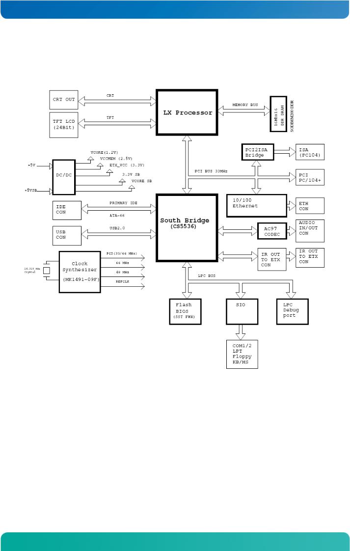
2.4Block Diagram
2.4.1 MSM800BEV
2.5MICROSPACE® Documentation
This manual is written for the original equipment manufacturer (OEM) who plans to build computer systems based on the single board MICROSPACE-PC. It is for integrators and programmers of systems based on the MICROSPACEComputer family. This manual provides instructions for installing and configuring the board and describes the system and setup requirements. This document contains information on hardware requirements, interconnections, and details of how to program the system. Please check the Product CD for further information and manuals.
12 |
www.kontron.com |

MSM800BEV / Introduction
2.6Product Photo
2.6.1 MSM800BEV
Top View, with Option 807041 (small cooler):
Bottom View:
13 |
www.kontron.com |

MSM800BEV / Specifications
3Specifications
|
Note: |
All information is subject to change without notice. |
||||||
|
|
|
|
|
|
|
|
|
|
|
|
|
|
|
|
|
|
|
|
CPU |
|
|
|
|
|
|
|
|
|
|
|
|
|
|
|
|
|
CPU |
|
|
Geode LX800 |
|
|
|
|
|
CPU Core Supply |
|
1.8V very low powered |
|
|
||
|
|
Mode |
|
|
Real/Protected |
|
|
|
|
|
Compatibility |
|
8086 – P5 |
|
|
|
|
|
|
Word Size |
|
32bits |
|
|
|
|
|
|
Secondary Cache |
|
– |
|
|
|
|
|
|
Physical Addressing |
|
32 lines |
|
|
|
|
|
|
Virtual Addressing |
|
16GBytes |
|
|
|
|
|
|
Clock Rates |
|
500MHz |
|
|
|
|
|
|
Socket Standard |
|
Soldered BGA |
|
|
|
|
|
|
|
|
|
|
|
|
|
|
|
Chipset |
|
|
|
|
|
|
|
|
|
|
|
|
|
|
|
|
|
Northbridge |
|
AMD LX800 |
|
|
|
|
|
|
Southbridge |
|
AMD 5536 |
|
|
|
|
|
|
LAN |
|
|
10/100Mbit Intel 82C551ER |
|
|
|
|
|
Audio |
|
|
AC97 – V2.3 |
|
|
|
|
|
Firewire IEEE1394 |
|
Not onboard |
|
|
|
|
|
|
Video |
|
|
16MByte Video-DDRAM |
|
|
|
|
|
|
|
|
|
|
|
|
|
|
Power Management |
|
|
|
|
|
|
|
|
|
|
|
|
|||
|
|
|
|
|
The LX800/900 supports ACPI and APM Version 1.2. |
|
|
|
|
|
|
|
|
The following ACPI Sleep States are supported: |
|
|
|
|
|
|
|
|
» S1 |
Sleep with CPU content. |
|
|
|
|
|
|
|
» S4 |
Hibernation (LED is blinking) with transition to S5. |
|
|
|
|
Available since V2.0 |
|
» S5-G2 |
Power Off (LED is blinking). |
|
|
|
|
|
|
|
|
|
The device can be switched on by the Main Button (or with WOL if available). |
|
|
|
|
|
|
|
» S5-G3 |
Power Off (mechanically) |
|
|
|
|
|
|
|
= if available |
|
|
|
|
|
|
|
|
|
|
|
|
|
|
DMA |
|
|
|
|
|
|
|
|
|
|
|
|
|||
|
|
8237A comp. |
|
4 channel 8bits |
|
|
||
|
|
|
3 channel 16bits |
|
|
|||
|
|
|
|
|
|
|
||
|
|
|
|
|
|
|
|
|
|
|
Interrupts |
|
|
|
|
|
|
|
|
|
|
|
||||
|
|
8259 comp. |
|
8 + 7 levels, PC compatible |
|
|
||
|
|
|
|
|
|
|
|
|
|
|
Timers |
|
|
|
|
|
|
|
|
|
|
|
||||
|
|
8254 comp. |
|
3 programmable counters/timers |
|
|
||
|
|
|
|
|
|
|
|
|
|
|
Memory |
|
|
|
|
|
|
|
|
|
|
|
||||
|
|
MSM800BEV |
|
SODIMM200pin DDR PC2700 333MHz 128-1024MByte |
|
|
||
14 |
www.kontron.com |

MSM800BEV / Specifications
Video
|
|
Controller |
|
MSM800BEV |
|
|
|
|
|
|
|
|
|
|
|
|
|||||
|
|
Bus |
|
|
32bit high speed 33MHz PCI bus |
|
|
|
|
|
|
|
|||||||||
|
|
Enhanced BIOS |
|
|
VGA/LCD BIOS |
|
|
|
|
|
|
|
|
|
|
|
|
||||
|
|
Memory |
|
|
2-254MByte shared RAM |
|
|
|
|
|
|
|
|
|
|||||||
|
|
CRT-Monitor |
|
|
VGA, SVGA up to 1920x1440 |
|
|
|
|
|
|
|
|
|
|||||||
|
|
Flat Panel |
|
|
TFT |
3.3V |
18/24bit up to 1600x1200 |
|
|
|
|
|
|
|
|||||||
|
|
Controller Modes |
|
|
CRT only; flat panel only; or simultaneous CRT and flat panel |
|
|
|
|||||||||||||
|
|
Video Input |
|
|
No |
|
|
|
|
|
|
|
|
|
|
|
|
||||
|
|
Drivers |
|
|
WIN2000, XP |
|
|
|
|
|
|
|
|
|
|
|
|
||||
|
|
|
|
|
|
|
|
|
|
|
|
|
|
|
|
|
|
|
|
|
|
|
|
Mass Storage |
|
|
|
|
|
|
|
|
|
|
|
|
|
|
|
|
|
|
|
|
|
|
|
|
|
|
|
|
|
|
|
|
|
|
|
|
|
|
|||
|
|
FD |
|
Floppy disk interface, for max. 1 floppy with 26pin connector |
|
|
|
||||||||||||||
|
|
HD |
|
|
E-IDE interface, AT-type, for max. 2 hard disks, 44pin connector, for 1.3, 1.8 and 2.5" hard |
||||||||||||||||
|
|
|
|
disks with 44 pins IDE |
|
|
|
|
|
|
|
|
|
||||||||
|
|
|
|
|
|
|
|
|
|
|
|
|
|
||||||||
|
|
|
|
|
|
|
|
|
|
|
|
|
|
|
|
|
|
|
|
|
|
|
|
Standard AT Interfaces |
|
|
|
|
|
|
|
|
|
|
|
|
|
|
|
|
|
|
|
|
|
|
|
|
|
|
|
|
|
|
|
|
|
|
|
|
|
|
|
|
|
|
|
|
|
|
Name |
|
FIFO |
|
IRQs |
|
|
Address |
|
|
Standard |
|
Option |
||||
|
|
Serial |
|
COM1 |
|
|
yes |
|
|
IRQ4 |
|
|
3F8 |
|
|
RS232C |
|
|
|||
|
|
|
COM2 |
|
|
yes |
|
|
IRQ3 |
|
|
2F8 |
|
|
RS232C |
|
|
||||
|
|
|
|
|
|
|
|
|
|
|
|
|
|
|
|||||||
|
|
|
|
|
(Baud rates: 50-115 KBaud programmable) |
|
|
|
|
|
|
|
|||||||||
|
|
Parallel |
|
|
LPT1 printer interface mode: SPP(output), EPP (bidirectional) |
(Centronics) |
|||||||||||||||
|
|
Keyboard |
|
|
AT or PS/2 –keyboard |
|
|
|
|
|
|
|
|
|
|||||||
|
|
Mouse |
|
|
PS/2 |
|
|
|
|
|
|
|
|
|
|
|
|
||||
|
|
Speaker |
|
|
0.1 W output drive |
|
|
|
|
|
|
|
|
|
|
|
|||||
|
|
RTC |
|
|
Integrated into the chipset, RTC with CMOS-RAM 256Byte |
|
|
|
|||||||||||||
|
|
Backup Current |
|
|
<5 A |
|
|
|
|
|
|
|
|
|
|
|
|
||||
|
|
Non-chargeable Battery |
|
|
MSM800BEV: |
|
3.6V lithium 400mAh internally or externally connected |
||||||||||||||
|
|
|
|
|
|
|
|
|
|
|
|
|
|
|
|
|
|
|
|
|
|
|
|
Bus |
|
|
|
|
|
|
|
|
|
|
|
|
|
|
|
|
|
|
|
|
|
|
|
|
|
|
|
|
|
|
|
|
|
|
|||||||
|
|
PC/104 ISA |
|
IEEE-996 standard ISA bus, buffered |
|
|
|
|
|
|
|
||||||||||
|
|
|
MSM800BEV: |
|
full 16bit ISA support |
|
|
|
|
|
|
|
|||||||||
|
|
|
|
|
|
|
|
|
|
|
|
|
|||||||||
|
|
Clock |
|
|
8MHz defined by the Geode |
|
|
|
|
|
|
|
|
|
|||||||
|
|
|
|
|
|
|
|
|
|
|
|
|
|
|
|
|
|
|
|
|
|
|
|
USB |
|
|
|
|
|
|
|
|
|
|
|
|
|
|
|
|
|
|
|
|
|
|
|
|
|
|
|
|
|
|
|
|
|
|
|
|
|
|
|
|
|
|
|
USB |
|
2.0 |
|
|
|
|
|
|
|
|
|
|
|
|
|
|
|
|
|
|
|
Transfer Rate |
|
|
400MBps, 12.5MBps/1.5MBps |
|
|
|
|
|
|
|
|
|
|||||||
|
|
Channels |
|
|
4 |
|
|
|
|
|
|
|
|
|
|
|
|
|
|
|
|
|
|
|
|
|
|
|
|
|
|
|
|
|
|
|
|
|
|
|
|
|
|
|
|
Peripheral Extension |
|
|
|
|
|
|
|
|
|
|
|
|
|
|
|
|
|
|
|
|
|
|
|
|
|
|
|
|
|
|
|
|
|
|
|
|
|
|
|||
|
|
ISA |
|
With PC/104 bus |
|
|
|
|
|
|
|
|
|
|
|
||||||
|
|
|
MSM800BEV: |
no ISA limitation |
|
|
|
|
|
|
|
||||||||||
|
|
|
|
|
|
|
|
|
|
|
|
||||||||||
|
|
PCI |
|
|
With PC/104-Plus bus |
|
|
|
|
|
|
|
|
|
|||||||
|
|
|
|
MSM800BEV: |
4 slots – max. 4 master devices |
|
|
|
|||||||||||||
|
|
|
|
|
|
|
|
||||||||||||||
15 |
www.kontron.com |

MSM800BEV / Specifications
Power Supply
|
Working |
|
5 Volts ± 5% |
|
|
|
|
|
|
|
||
|
Power Rise Time |
|
Unspecified |
|
|
|
|
|
|
|
||
|
Power Consumption |
|
MSM800SEV V2.1 with HD, MS/KB (PS/2), CRT monitor, WindowsXP Desktop: typ. 7.5-10W |
|
||||||||
|
|
|
MSM800BEV: |
|
|
|
|
|||||
|
Standby Power Consumption |
|
Windows Standby: |
2.5W (without MS/KB wake-up function) |
|
|||||||
|
|
|
Windows Standby: |
4.5W (with PS/2 wake-up function) |
|
|||||||
|
|
|
|
|
|
|
|
|
|
|
|
|
|
Physical Characteristics |
|
|
|
|
|
|
|
|
|
|
|
|
|
|
|
|
|
|
|
|
|
|
|
|
|
|
|
Length: |
90mm |
|
|
|
|
||||
|
Dimensions |
|
Depth: |
96/99mm |
|
|
|
|
||||
|
|
|
Height: |
17-25mm |
|
|
|
|
||||
|
Weight |
|
90-170gr depending on model and cooler option |
|
||||||||
|
PCB Thickness |
|
1.6mm / 0.0625 inches nominal |
|
|
|
||||||
|
PCB Layer |
|
Multilayer |
|
|
|
|
|
|
|
||
|
|
|
|
|
|
|
|
|
|
|
|
|
|
Operating Environment |
|
|
|
|
|
|
|
|
|
|
|
|
|
|
|
|
|
|
|
|
|
|
||
|
Relative Humidity |
|
5-90% non-condensing |
|
|
|
|
|||||
|
Vibration |
|
5 to 2000Hz, 0.1G |
|
|
|
|
|||||
|
Shock |
|
1 g |
|
|
|
|
|
|
|
|
|
|
|
|
|
|
|
|
|
|
|
|
|
|
|
Temperature |
|
|
|
|
|
|
|
|
|
|
|
|
|
|
|
|
|
|
|
|
||||
|
Storage |
|
|
|
|
|
All models: |
-55°C to +85°C |
|
|||
|
Operating Temperature without Cooler |
|
|
|
|
All models: |
0°C to +60°C |
|
||||
|
Operating Temperature with 807041 |
|
|
|
|
All models: |
-25°C to +70°C |
|
||||
|
Extended Operating Temperature with 807042 |
|
|
Model BEV with E48: |
-40°C to +85°C |
|
||||||
|
Extended Operating Temp. with 807043 and E48 |
|
|
Model BEV: |
|
-40°C to +85°C |
|
|||||
|
|
|
|
|
|
|
|
|
|
|
||
|
EMI / EMC (IEC1131-2 refer MIL 461/462) |
|
|
|
|
|
|
|
|
|
||
|
|
|
|
|
|
|
||||||
|
|
|
|
|
|
IEC 801-2, EN55101-2, VDE 0843/0847 Part 2 |
|
|||||
|
ESD Electro Static Discharge |
|
|
|
Metallic protection needed |
|
|
|||||
|
|
|
|
Separate ground layer included |
|
|
||||||
|
|
|
|
|
|
|
|
|||||
|
|
|
|
|
|
15 kV single peak |
|
|
|
|||
|
REF Radiated Electromagnetic Field |
|
|
|
IEC 801-3, VDE 0843 Part 3, IEC770 6.2.9. (not tested) |
|
||||||
|
|
|
|
|
|
IEC 801-4, EN50082-1, VDE 0843 Part 4 |
|
|||||
|
EFT Electric Fast Transient (Burst) |
|
|
|
250V - 4kV, 50 Ohms, Ts=5ns |
|
|
|||||
|
|
|
|
|
|
Grade 2: 1kV Supply, 500 I/O, 5kHz |
|
|||||
|
|
|
|
|
|
IEC 801-5, IEEE587, VDE 0843 Part 5 |
|
|||||
|
SIR Surge Immunity Requirements |
|
|
|
|
Supply: |
2kV, |
6 pulse/minute |
|
|||
|
|
|
|
|
I/O: |
500V, 2 pulse/minute |
|
|||||
|
|
|
|
|
|
|
|
|||||
|
|
|
|
|
|
|
FD, CRT: |
none |
|
|
|
|
|
High-frequency Radiation |
|
|
|
EN55022 |
|
|
|
|
|||
|
|
|
|
|
|
|
|
|
|
|
|
|
|
Compatibility |
|
|
|
|
|
|
|
|
|
|
|
|
|
|
|
|
|
|
||||||
|
MSM800BEV |
|
|
|
Mechanically compatible to Kontron Compact Computers MSMx86 boards and to |
|
||||||
|
|
|
|
all other PC/104 boards. |
|
|
||||||
|
|
|
|
|
|
|
|
|||||
Note: All information is subject to change without notice.
16 |
www.kontron.com |
MSM800BEV / Quick Start Guide
4Quick Start Guide
Warning: |
ESD Sensitive Device! Place the embedded computer board on an isolated, ESD-protected surface. |
|
Ensure that all equipment, tools and people are fully protected against ESD. |
|
|
4.1Print Manuals from the Product CD
Place the Product CD into the CD drive of a personal computer with a connected printer.
Open the CD; open the directory Manuals/MSM800.
Print out the required manuals (for example the BIOS manual or the User's Guide).
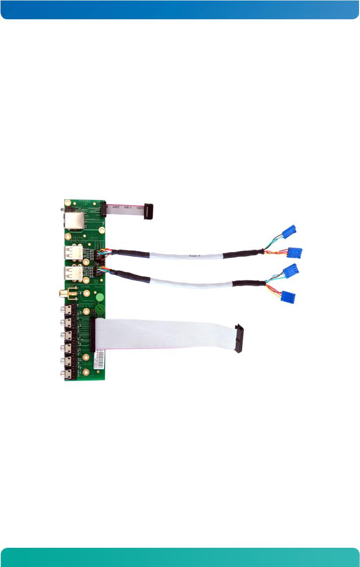
4.2The MSM800CON, Part Nr. 803036
The MSM800CON must be ordered separately.
17 |
www.kontron.com |
MSM800BEV / Quick Start Guide
The MSM800CON connected to an MSM800BEV board:
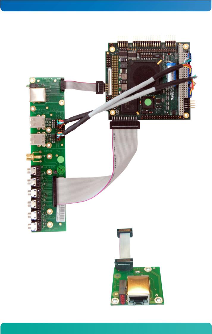
4.3The LANCON, Part Nr. 803046
18 |
www.kontron.com |
MSM800BEV / Quick Start Guide
4.4The DVICON, Part Nr. 803042
The DVICON connected to an MSM800BEV board:
19 |
www.kontron.com |

MSM800BEV / Quick Start Guide
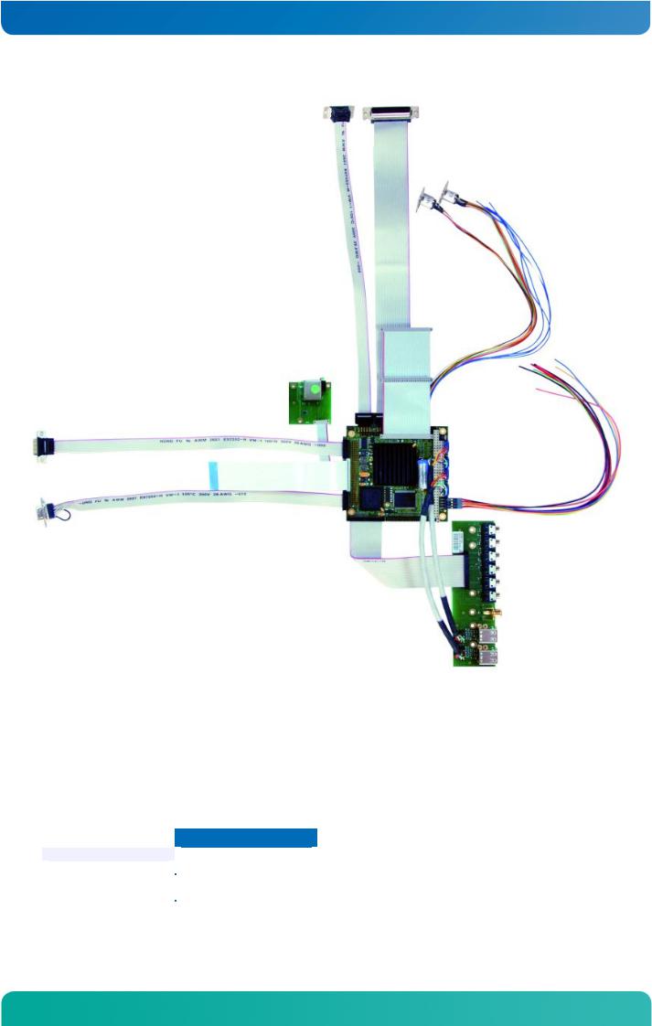
4.5Connect Peripherals to the Board
Prepare the following peripherals:
»VGA monitor (LCD or CRT) with a resolution up to 1024x768 pixel
»PS2 keyboard
»USB mouse
»LAN cable, if available
»Hard disk or CompactFlash
»USB CD drive or floppy drive
»Power supply with 5 Volts and min. 30 Watts
Make sure the polarity is correct. Otherwise the hard disk and/or electronic board may be destroyed.
1.Connect the VGA monitor to the 15pin high density DSub-connector.
2.Connect the keyboard to the PS/2 connector.
3.Connect the USB mouse to one of the USB connectors.
4.Connect the hard disk with a 44pin cable to the IDE connector.
Alternatively to the hard disk, the CompactFlash card may be inserted into the CF socket.
Pin1 of the cable must go to Pin1 of the connector, which has a red mark next to it (not visible in the photo).
5.Connect a USB CD-Drive or a USB Floppy drive to one of the USB connectors.
6.Insert a boot device: USB stick, floppy, hard disk or bootable CF.
20 |
www.kontron.com |
MSM800BEV / Quick Start Guide
MSM800SEV with the contents of the Cable Kit (CKCON):
All of the above cables and PCB connectors are included in the MSM800CKCON, Part Nr. 803035 (the MSM800 board is not included).
4.6The Development Kit, Part Nr. 802118
The Development Kit (DK) allows for an immediate start-up with the embedded system. The hard disk includes a DOS and a LINUX kernel V2.6 boot partition.
The following material is included in the current MSM800DK:
Item |
Part Number |
|
|
|
|
1x MSM800BEV |
802110 |
|
1x MSM800CKCON |
803035 |
|
1x MSM800DVICON |
803042 |
|
1x |
256MB DRAM |
890670 |
1x |
3.5" floppy drive |
891001 |
1x |
2.5" hard disk |
890003 |
21 |
www.kontron.com |
MSM800BEV / Quick Start Guide
4.7Power Up the Board
1.Check that the voltage is regulated to +5Volt and that the polarity is correct.
Attention! The supply voltage must be in the range of 4.9Volt to maximum 5.25Volt.
2.Switch on the connected monitor.
3.Switch on the external 5V power supply.
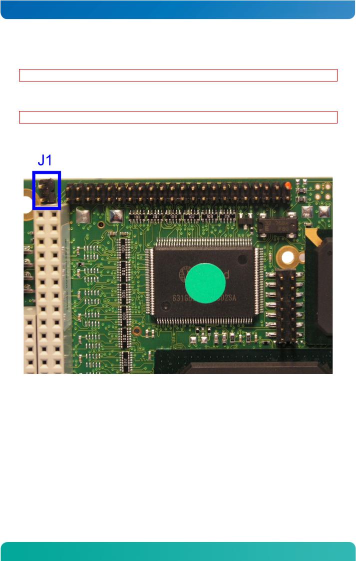
Attention! Jumper J1 determines the mode of the CompactFlash disk.
J1 – CF Master
22 |
www.kontron.com |
MSM800BEV / Quick Start Guide
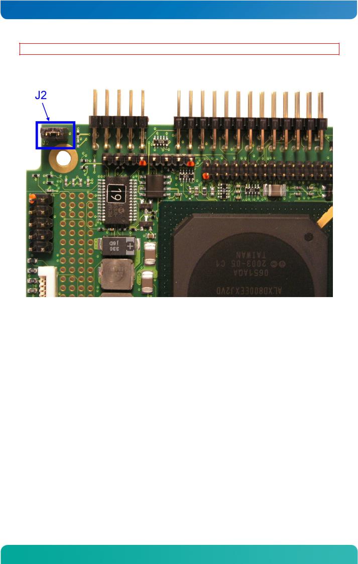
Attention! Jumper J2 determines the behavior after power-on.
J2 – Autostart
In autostart mode the board will automatically enter the boot sequence and the green "Power LED" will turn on. In non-autostart mode the board will remain in standby mode until the power button is pressed.
23 |
www.kontron.com |
MSM800BEV / Quick Start Guide
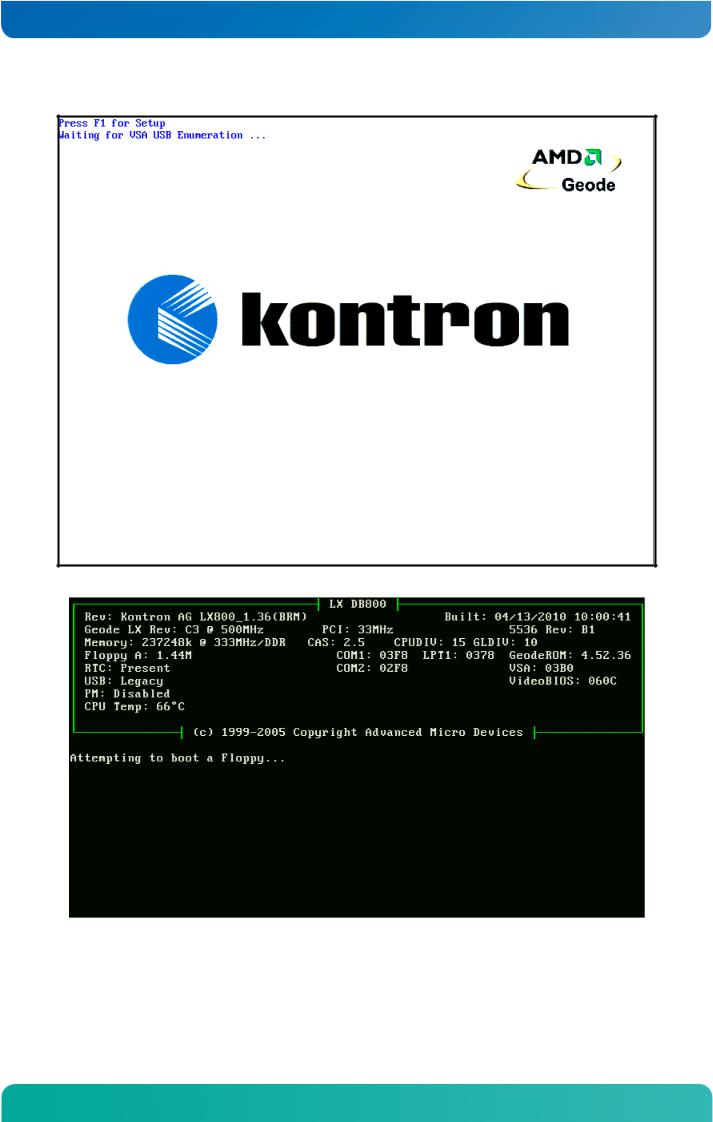
After a few seconds the screen should display the BIOS initial message/picture:
24 |
www.kontron.com |

MSM800BEV / Quick Start Guide
4.8BIOS Setup
Since the BIOS is auto-configuring during the start-up procedure, the user normally does not enter the BIOS setup. Manual setup is needed only to change the default settings. Please refer to the driver/software/BIOS manual printed from the Product CD for the BIOS setup details.
4.9Boot Up the Operating System and Install the Drivers
Depending on which boot drive is available, boot up the operating system from the CompactFlash, hard disk, or floppy disk.
To install the drivers, see the BIOS/Driver/Software/ manual on the Product CD.
25 |
www.kontron.com |

MSM800BEV / Connectors & Jumpers
5Connectors & Jumpers
5.1Connectors
The following pages describe the connector pin-out for all current MSM800 boards.
Flat cable |
|
|
|
44pin IDE is: |
IDT Terminal for Dual Row (2.00mm grid) and 1.00mm flat cable |
||
All others are: |
IDT Terminal for Dual Row 0.1" (2.54mm grid) and 1.27mm flat cable |
||
NC: |
not connected |
|
|
|
|
|
|
Connector |
Structure |
Pin |
Remarks |
|
|
|
|
X1 |
Power |
2x4 |
2.54mm |
|
|
|
|
X10 |
VGA |
2x5 |
2.54mm |
|
|
|
|
X15 |
LCD |
2x22 |
2mm |
|
|
|
|
X29 |
Sound Audio I/O |
2x15 |
2.00mm |
|
|
|
|
X30 |
LPT1 |
2x13 |
2.54mm |
|
|
|
|
X31 |
Keyboard, mouse, utility |
2x5 |
2.54mm |
|
|
|
|
X33 |
LAN / Battery |
2x5 |
2.00mm |
|
|
|
|
X38 |
COM1 |
2x5 |
2.54mm |
|
|
|
|
X39 |
COM2 |
2x5 |
2.54mm |
|
|
|
|
X44 |
IrDA |
4 |
2.54mm |
|
|
|
|
X50 |
USB 1 |
4 |
2.54mm |
|
|
|
|
X51 |
USB 2 |
4 |
2.54mm |
|
|
|
|
X52 |
USB 3 |
4 |
2.54mm |
|
|
|
|
X53 |
USB 4 |
4 |
2.54mm |
|
|
|
|
X60 |
IDE |
2x22 |
2mm |
|
|
|
|
X70 |
Floppy |
26 |
FCC micro |
|
|
|
|
X71 |
CompactFlash Holder |
|
|
|
|
|
|
X101 |
PC104+ |
120 |
2mm |
|
|
|
|
X102 |
PC104 |
104 |
2.54mm |
|
|
|
|
X110 |
POD Port |
2x7 |
2mm |
|
|
|
|
X230 |
JTAG-Port |
4 |
2.54mm |
|
|
|
|
X300 |
SODIMM |
144 |
0.8mm |
|
|
|
|
26 |
www.kontron.com |
MSM800BEV / Connectors & Jumpers
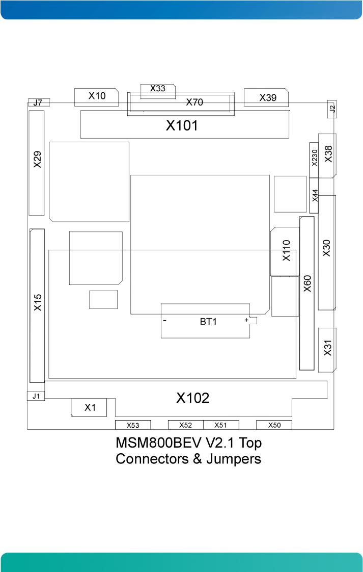
5.1.1 Top Side of the MSM800BEV V2.1
27 |
www.kontron.com |
MSM800BEV / Connectors & Jumpers
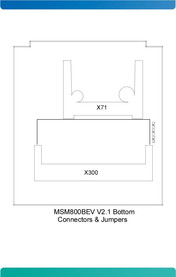
5.1.2 Bottom Side of the MSM800BEV V2.1
With CompactFlash (Option 807007, connector X71).
28 |
www.kontron.com |
Loading...