


 Loading...
COMe-bHL6
Document Revision 111
www.kontron.com

» Table of Contents « |
|
|
1 |
User Information.................................................................................. |
6 |
1.1 |
About This Document.................................................................................................................... |
6 |
1.2 |
Copyright Notice.......................................................................................................................... |
6 |
1.3 |
Trademarks................................................................................................................................. |
6 |
1.4 |
Standards................................................................................................................................... |
6 |
1.5 |
Warranty.................................................................................................................................... |
7 |
1.6 |
Technical Support......................................................................................................................... |
7 |
2 |
Introduction........................................................................................ |
8 |
2.1 |
Product Description...................................................................................................................... |
8 |
2.2 |
Naming clarification..................................................................................................................... |
8 |
2.3 |
Understanding COM Express® Functionality....................................................................................... |
9 |
2.4 |
COM Express® Documentation....................................................................................................... |
10 |
2.5 |
COM Express® Benefits................................................................................................................ |
10 |
3 |
Product Specification........................................................................... |
11 |
3.1 |
Module definition....................................................................................................................... |
11 |
3.2 |
Functional Specification............................................................................................................... |
12 |
3.3 |
Block Diagram............................................................................................................................ |
21 |
3.4 |
Accessories............................................................................................................................... |
22 |
3.5 |
Electrical Specification................................................................................................................ |
23 |
3.5.1 |
Supply Voltage........................................................................................................................... |
23 |
3.5.2 |
Power Supply Rise Time................................................................................................................ |
23 |
3.5.3 |
Supply Voltage Ripple.................................................................................................................. |
23 |
3.5.4 |
Power Consumption..................................................................................................................... |
23 |
3.5.5 |
ATX Mode.................................................................................................................................. |
24 |
3.5.6 |
Single Supply Mode..................................................................................................................... |
24 |
3.6 |
Power Control............................................................................................................................ |
25 |
3.7 |
Environmental Specification......................................................................................................... |
26 |
3.7.1 |
Temperature Specification............................................................................................................ |
26 |
3.7.2 |
Humidity................................................................................................................................... |
26 |
3.8 |
Standards and Certifications......................................................................................................... |
27 |
3.9 |
MTBF........................................................................................................................................ |
29 |
3.10 |
Mechanical Specification.............................................................................................................. |
30 |
3.11 |
Module Dimensions..................................................................................................................... |
31 |
3.12 |
Thermal Management, Heatspreader and Cooling Solutions................................................................. |
32 |
3.13 |
Onboard Connectors.................................................................................................................... |
33 |
3.13.1 |
FAN Connector J6 - PCB bottom...................................................................................................... |
33 |
3.13.2 |
CPU JTAG connector J3 - PCB bottom............................................................................................... |
34 |
3.13.3 |
CPLD Debug connector J7 - PCB top................................................................................................. |
34 |
4 |
Features and Interfaces....................................................................... |
35 |
4.1 |
S5 Eco Mode.............................................................................................................................. |
35 |
www.kontron.com

COMe-bHL6 /
4.2 |
Rapid Shutdown......................................................................................................................... |
36 |
4.3 |
LPC.......................................................................................................................................... |
38 |
4.4 |
Serial Peripheral Interface (SPI).................................................................................................... |
39 |
4.5 |
SPI boot.................................................................................................................................... |
39 |
4.6 |
M.A.R.S..................................................................................................................................... |
41 |
4.7 |
UART........................................................................................................................................ |
42 |
4.8 |
Fast I2C.................................................................................................................................... |
43 |
4.9 |
Dual Staged Watchdog Timer......................................................................................................... |
44 |
4.10 |
Intel® Fast Flash Standby™ / Rapid Start Technology™....................................................................... |
45 |
4.11 |
Speedstep Technology.................................................................................................................. |
47 |
4.12 |
C-States.................................................................................................................................... |
48 |
4.13 |
Hyper Threading......................................................................................................................... |
49 |
4.14 |
Dynamic FSB Frequency Switching.................................................................................................. |
50 |
4.15 |
VID-x........................................................................................................................................ |
51 |
4.16 |
Intel® Turbo Boost Technology and AVX........................................................................................... |
52 |
4.17 |
Display Configuration.................................................................................................................. |
53 |
4.18 |
Hybrid Graphics / Multi-monitor.................................................................................................... |
56 |
4.19 |
Intel® Wireless Display................................................................................................................ |
57 |
4.20 |
Intel® vPro™ technology.............................................................................................................. |
59 |
4.21 |
ACPI Suspend Modes and Resume Events.......................................................................................... |
60 |
5 |
System Resources................................................................................ |
61 |
5.1 |
Interrupt Request (IRQ) Lines........................................................................................................ |
61 |
5.2 |
Memory Area............................................................................................................................. |
62 |
5.3 |
I/O Address Map......................................................................................................................... |
62 |
5.4 |
Peripheral Component Interconnect (PCI) Devices............................................................................. |
63 |
5.5 |
Internal I2C Bus......................................................................................................................... |
63 |
5.6 |
External I2C Bus......................................................................................................................... |
63 |
5.7 |
System Management (SM) Bus....................................................................................................... |
64 |
6 |
Connectors........................................................................................ |
65 |
6.1 |
Connector Location..................................................................................................................... |
65 |
7 |
Pinout List......................................................................................... |
66 |
7.1 |
General Signal Description............................................................................................................ |
66 |
7.2 |
Connector X1A Row A................................................................................................................... |
67 |
7.3 |
Connector X1A Row B................................................................................................................... |
69 |
7.4 |
Connector X1B Row C................................................................................................................... |
71 |
7.5 |
Connector X1B Row D................................................................................................................... |
73 |
8 |
BIOS Operation................................................................................... |
75 |
8.1 |
Determining the BIOS Version........................................................................................................ |
75 |
8.2 |
BIOS Update.............................................................................................................................. |
75 |
8.3 |
POST Codes................................................................................................................................ |
75 |
4

COMe-bHL6 / User Information
8.4 |
Setup Guide |
............................................................................................................................... 75 |
8.5 |
BIOS Setup................................................................................................................................ |
76 |
8.5.1 |
Main........................................................................................................................................ |
76 |
8.5.2 |
Advanced.................................................................................................................................. |
83 |
8.5.3 |
Security.................................................................................................................................. |
125 |
8.5.4 |
Boot....................................................................................................................................... |
127 |
8.5.5 |
Exit........................................................................................................................................ |
128 |
5

COMe-bHL6 / User Information
1User Information
1.1About This Document
This document provides information about products from Kontron Europe GmbH and/or its subsidiaries. No warranty of suitability, purpose, or fitness is implied. While every attempt has been made to ensure that the information in this document is accurate, the information contained within is supplied “as-is” and is subject to change without notice.
For the circuits, descriptions and tables indicated, Kontron assumes no responsibility as far as patents or other rights of third parties are concerned.
1.2Copyright Notice
Copyright © 2003-2014 Kontron Europe GmbH
All rights reserved. No part of this document may be reproduced, transmitted, transcribed, stored in a retrieval system, or translated into any language or computer language, in any form or by any means (electronic, mechanical, photocopying, recording, or otherwise), without the express written permission of Kontron Europe GmbH.
DIMM-PC®, PISA®, ETX®, ETXexpress®, microETXexpress®, X-board®, DIMM-IO® and DIMM-BUS® are trademarks or registered trademarks of Kontron Europe GmbH. Kontron is trademark or registered trademark of Kontron AG.
1.3Trademarks
The following lists the trademarks of components used in this board.
»IBM, XT, AT, PS/2 and Personal System/2 are trademarks of International Business Machines Corp.
»Microsoft is a registered trademark of Microsoft Corp.
»Intel is a registered trademark of Intel Corp.
»All other products and trademarks mentioned in this manual are trademarks of their respective owners.
1.4Standards
Kontron Europe GmbH is certified to ISO 9000 standards.
6

COMe-bHL6 / User Information
1.5Warranty
For this Kontron Europe GmbH product warranty for defects in material and workmanship exists as long as the warranty period, beginning with the date of shipment, lasts. During the warranty period, Kontron Europe GmbH will decide on its discretion if defective products are to be repaired or replaced.
Within the warranty period, the repair of products is free of charge as long as warranty conditions are observed.
Warranty does not apply for defects arising/resulting from improper or inadequate maintenance or handling by the buyer, unauthorized modification or misuse, as well as the operation outside of the product´s environmental specifications and improper installation and maintenance.
Kontron Europe GmbH will not be responsible for any defects or damages to other products not supplied by Kontron Europe GmbH that are caused by a faulty Kontron Europe GmbH product.
1.6Technical Support
Technicians and engineers from Kontron Europe GmbH and/or its subsidiaries are available for technical support. We are committed to make our product easy to use and will help you use our products in your systems.
Please consult our Website at http://www.kontron.com/support for the latest product documentation, utilities, drivers and support contacts. Consult our customer section http://emdcustomersection.kontron.com for the latest BIOS downloads, Product Change Notifications, Board Support Packages, DemoImages, 3D drawings and additional tools and software. In any case you can always contact your board supplier for technical support.
7

COMe-bHL6 / Introduction
2Introduction
2.1Product Description
The brand new application-ready COMe-bHL6 offers increased performance density and up to twice the graphics performance compared to its predecessors. Up to three independent, daisy-chained displays with up to 4K resolution are supported to create stunning user experiences. Further to this, DirectX® 11.1 and OpenGL 4.0 support paves the way for compelling visuals when videos, graphics and interactive content are being displayed. By integrating the new Intel® AVX2 and OpenCL 1.2, Kontron’s new Computer-on-Modules additionally not only provide an increase in floating-point performance they also possess improved parallel processing capacities. Typical application areas can be found in markets such as digital signage, professional gaming and entertainment, medical imaging and surveillance and security as well as industrial plant and machine line control on shop floorand control room-level.
Engineers can immediately commence with evaluating these new benchmark Computer-on-Modules on all Kontron COM Express® pin-out type 6-compliant starter kits.
The Kontron COM Express® pin-out type 6 COMe-bHL6 module is available in several different variants ranging from the cost-optimized low-power processor versions up to quad-core Intel® Core™ i7 processors with up to 4x 2.4 GHz. The modules are designed with the Intel® Mobile QM87 chipset, host up to 16 GB DDR3L RAM and support 7 PCI Express x1 lanes and 1 PEG x16 interface which is also compatible to standard PCI Express devices. Less complex peripherals can be connected via SPI and LPC. Additional dedicated features include 3x SATA 6Gb/s ports, 1 SATA 3Gb/s port, as well as Gigabit Ethernet, 4 USB 3.0 ports, 4 USB 2.0 and 2 serial ports. The Kontron COMe-bHL6 features comprehensive display support with 3x dual mode DisplayPort++ which can also output, HDMI, DVI and DisplayPort 1.2. Industrial applications benefit from the watchdog and real-time clock. The module supports an 8.5-20V wide-range power supply. The support of smart batteries via MARS and the standardized embedded application programming interface EAPI round off the feature set and provide engineers with a comprehensive service package that eases system development as well as system programming.
For customers wanting to instantly leverage the new graphics and computing power in their existing designs based on individual carrier boards, Kontron also offers standardized migration support services to accelerate the design-in phase and thus achieve fastest field deployment.
The Kontron COM Express® basic Computer-on-Module COMe-bHL6 supports the full Windows OS portfolio along with Linux and VxWorks.
2.2Naming clarification
COM Express® defines a Computer-On-Module, or COM, with all components necessary for a bootable host computer, packaged as a super component.
»COMe-bXX# modules are Kontron's COM Express® modules in basic form factor (125mm x 95mm)
»COMe-cXX# modules are Kontron's COM Express® modules in compact form factor (95mm x 95mm)
»COMe-mXX# modules are Kontron's COM Express® modules in mini form factor (55mm x 84mm)
The product names for Kontron COM Express® Computer-on-Modules consist of a short form of the industry standard (COMe-), the form factor (b=basic, c=compact, m=mini), the capital letters for the CPU and Chipset Codenames (XX) and the pin-out type (#) followed by the CPU Name.
8

COMe-bHL6 / Introduction
2.3Understanding COM Express® Functionality
All Kontron COM Express® basic and compact modules contain two 220pin connectors; each of it has two rows called Row A & B on primary connector and Row C & D on secondary connector. COM Express® Computer-on-modules feature the following maximum amount of interfaces according to the PICMG module Pin-out type:
Feature |
Pin-Out Type 1 |
Pin-Out Type 10 |
Pin-Out Type 2 |
Pin-Out Type 6 |
HD Audio |
1x |
1x |
1x |
1x |
Gbit Ethernet |
1x |
1x |
1x |
1x |
Serial ATA |
4x |
4x |
4x |
4x |
Parallel ATA |
- |
- |
1x |
- |
PCI |
- |
- |
1x |
- |
PCI Express x1 |
6x |
6x |
6x |
8x |
PCI Express x16 (PEG) |
- |
- |
1x |
1x |
USB Client |
1x |
1x |
- |
- |
USB 2.0 |
8x |
8x |
8x |
8x |
USB 3.0 |
- |
2x |
- |
4x |
VGA |
1x |
- |
1x |
1x |
LVDS |
Dual Channel |
Single Channel |
Dual Channel |
Dual Channel |
DP++ (SDVO/DP/HDMI/DVI) |
1x optional |
1x |
3x shared with PEG |
3x |
LPC |
1x |
1x |
1x |
1x |
External SMB |
1x |
1x |
1x |
1x |
External I2C |
1x |
1x |
1x |
1x |
GPIO |
8x |
8x |
8x |
8x |
SDIO shared w/GPIO |
1x optional |
1x optional |
- |
1x optional |
UART (2-wire COM) |
- |
2x |
- |
2x |
FAN PWM out |
- |
1x |
- |
1x |
|
|
|
|
|
9

COMe-bHL6 / Introduction
2.4COM Express® Documentation
This product manual serves as one of three principal references for a COM Express® design. It documents the specifications and features of COMe-bHL6. Additional references are available at your Kontron Support or at PICMG®:
»The COM Express® Specification defines the COM Express® module form factor, pin-out, and signals. This document is available at the PICMG® website by filling out the order form.
»The COM Express® Design Guide by PICMG® serves as a general guide for baseboard design, with a focus on maximum flexibility to accommodate a wide range of COM Express® modules.
Some of the information contained within this product manual applies only to certain product revisions (CE: xxx). If certain information applies to specific product revisions (CE: xxx) it will be stated. Please check the product revision of your module to see if this information is applicable.
2.5COM Express® Benefits
COM Express® modules are very compact, highly integrated computers. All Kontron COM Express® modules feature a standardized form factor and a standardized connector layout which carry a specified set of signals. Each COM is based on the COM Express® specification. This standardization allows designers to create a single-system baseboard that can accept present and future COM Express® modules.
The baseboard designer can optimize exactly how each of these functions implements physically. Designers can place connectors precisely where needed for the application on a baseboard designed to optimally fit a system’s packaging.
A single baseboard design can use a range of COM Express® modules with different sizes and pin-outs. This flexibility can differentiate products at various price/performance points, or when designing future proof systems that have a built-in upgrade path. The modularity of a COM Express® solution also ensures against obsolescence when computer technology evolves. A properly designed COM Express® baseboard can work with several successive generations of COM Express® modules.
A COM Express® baseboard design has many advantages of a customized computer-board design and, additionally, delivers better obsolescence protection, heavily reduced engineering effort, and faster time to market.
10
COMe-bHL6 / Product Specification
3Product Specification
3.1Module definition
The COM Express® basic sized Computer-on-Module COMe-bHL6 (BHL6 / BBL6) follows pin-out Type 6 and is compatible to PICMG specification COM.0 Rev 2.1. The COMe-bHL6 based on latest Shark Bay Mobile platform is available in different variants to cover the demand of different performance, price and power:
Commercial grade modules (0°C to 60°C operating)
Product Number |
Product Name |
Processor |
TDP |
PCH |
USB 3.0 |
SATA 6G |
SATA 3G |
38025-0000-18-7 |
COMe-bHL6 i7-4860EQ |
Intel® Core™ i7-4860EQ |
47W |
QM87 |
4 |
3 |
1 |
38025-0000-16-7 |
COMe-bHL6 i7-4850EQ |
Intel® Core™ i7-4850EQ |
47W |
QM87 |
4 |
3 |
1 |
38025-0000-24-7 |
COMe-bHL6 i7-4700EQ |
Intel® Core™ i7-4700EQ |
47W/37W |
QM87 |
4 |
3 |
1 |
38025-0000-29-5 |
COMe-bHL6 i5-4410E |
Intel® Core™ i5-4410E |
37W |
QM87 |
4 |
3 |
1 |
38025-0000-27-5 |
COMe-bHL6 i5-4400E |
Intel® Core™ i5-4400E |
37W |
QM87 |
4 |
3 |
1 |
38025-0000-18-5 |
COMe-bHL6 i5-4422E |
Intel® Core™ i5-4422E |
25W |
QM87 |
4 |
3 |
1 |
38025-0000-16-5 |
COMe-bHL6 i5-4402E |
Intel® Core™ i5-4402E |
25W |
QM87 |
4 |
3 |
1 |
38025-0000-26-3 |
COMe-bHL6 i3-4110E |
Intel® Core™ i3-4110E |
37W |
HM86 |
2 |
2 |
2 |
38025-0000-24-3 |
COMe-bHL6 i3-4100E |
Intel® Core™ i3-4100E |
37W |
HM86 |
2 |
2 |
2 |
38025-0000-18-3 |
COMe-bHL6 i3-4112E |
Intel® Core™ i3-4112E |
25W |
HM86 |
2 |
2 |
2 |
38025-0000-16-3 |
COMe-bHL6 i3-4102E |
Intel® Core™ i3-4102E |
25W |
HM86 |
2 |
2 |
2 |
38025-0000-22-1 |
COMe-bHL6 2000E |
Intel® Celeron 2000E |
37W |
HM86 |
2 |
2 |
2 |
38025-0000-15-1 |
COMe-bHL6 2002E |
Intel® Celeron 2002E |
25W |
HM86 |
2 |
2 |
2 |
|
|
|
|
|
|
|
|
Extended temperature grade modules (E1, -25°C to 75°C operating) and
Industrial temperature grade modules (XT, -40°C to 85°C operating)
The COMe-bHL6 is available for extended and industrial temperature range. General capability was tested for following options:
»CPU: all
»Memory: E2 DDR3L memory only 97015-xxxx-16-3
»VCC: 12V only, no support for Wide-Range Input
The RXT product line includes modules with following featureset:
»industrial grade temperature range (-40 to +85°C) by screening
»ECC Memory support (97016-xxxx-16-3)
»Kontron Rapid Shutdown support
Product Number |
Product Name |
Processor |
TDP |
PCH |
USB 3.0 |
SATA 6G |
SATA 3G |
38026-0000-18-7 |
COMe-bHL6RXT i7-4860EQ |
Intel® Core™ i7-4860EQ |
47W |
QM87 |
4 |
3 |
1 |
38026-0000-24-7 |
COMe-bHL6RXT i7-4700EQ |
Intel® Core™ i7-4700EQ |
47W/37W |
QM87 |
4 |
3 |
1 |
38026-0000-29-5 |
COMe-bHL6RXT i5-4410E |
Intel® Core™ i5-4410E |
37W |
QM87 |
4 |
3 |
1 |
38026-0000-27-5 |
COMe-bHL6RXT i5-4400E |
Intel® Core™ i5-4400E |
37W |
QM87 |
4 |
3 |
1 |
38026-0000-18-5 |
COMe-bHL6RXT i5-4422E |
Intel® Core™ i5-4422E |
25W |
QM87 |
4 |
3 |
1 |
|
|
|
|
|
|
|
|
Please contact your local sales for further information and MOQ for RXT modules
11

COMe-bHL6 / Product Specification
3.2Functional Specification
Processor
The 22nm Intel® 4th Gen Core™ i7/i5/i3/Celeron® embedded (Haswell-H (Halo) / Crystal Well) CPU family with 37.5x32mm package size (BGA1364 socket) supports:
»Intel® Turbo Boost Technology 2.01
»Intel® 64
»Intel® Virtualization Technology (VT-x)
»Intel® Virtualization Technology for Directed I/O (VT-d)
»Intel® Hyper-Threading Technology
»Enhanced Intel SpeedStep® Technology
»Idle States (C-States)
»Intel® Smart Cache
»Thermal Monitoring Technologies
»Intel® Fast Memory Access
»Intel® Flex Memory Access
»Integrated Intel® HD Graphics with Dynamic Frequency Optional available (with customized BIOS, Evaluation Copy on request):
»Intel® vPRO™ Technology including:
»Intel® Active Management Technology (AMT)
»Intel® Trusted Execution Technology (TXT)
»Advanced Encryption Standard Instructions (AES-NI)
12

COMe-bHL6 / Product Specification
The integrated Intel® HD Graphics 5200/4600 supports:
»GraphicsTechnology GT3 with 40 Execution Units (HD5200)
»GraphicsTechnology GT2 with 20 Execution Units (HD4600)
»Intel® Quick Sync Video
»Intel® InTru™ 3D Technology
»Intel® Wireless Display
»Intel® Flexible Display Interface (Intel® FDI)
»Intel® Clear Video HD Technology
»Intel® Graphics Render C-State RC6
»Intel® Smart 2D Display Technology (S2DDT)
»3 simultaneous displays (Win7/8 and Linux)
»Hybrid Multi Monitor with 2 internal and 2 external displays
»Video Decode for AVC/H.264/VC-1/MPEG-2
»Video Encode for AVC/H.264/MPEG-2
»Blu-ray Playback (incl. PAVP)
The integrated Intel® HD Graphics supports:
»GraphicsTechnology GT1 with 10 Execution Units
»Dual Display
»Video Decode for AVC/H.264/VC-1/MPEG-2
»Video Encode for AVC/H.264/MPEG-2
»Blu-ray Playback (incl. PAVP)
13

COMe-bHL6 / Product Specification
CPU Features
Intel® |
Core™ |
Core™ |
Core™ |
Core™ |
Core™ |
Core™ |
Core™ |
Celeron@ |
Celeron@ |
- |
i7-4860EQ |
i7-4850EQ |
i7-4700EQ |
i5-4400E |
i5-4402E |
i3-4100E |
i3-4102E |
2000E |
2002E |
# of Cores |
4 |
4 |
4 |
2 |
2 |
2 |
2 |
2 |
2 |
# of Threads |
8 |
8 |
8 |
4 |
4 |
4 |
4 |
2 |
2 |
TDP Core frequency (HFM) |
1800MHz |
1600MHz |
2400MHz |
2700MHz |
1600MHz |
2400MHz |
1600MHz |
2200MHz |
1500MHz |
Max Turbo Frequency 1 core |
3200MHz |
3200MHz |
3400MHz |
3300MHz |
2700MHz |
- |
- |
- |
- |
Max Turbo all cores |
2600MHz |
2600MHz |
2800MHz |
3200MHz |
2600MHz |
- |
- |
- |
- |
LFM/LPM Frequency |
800MHz |
800MHz |
800MHz |
800MHz |
800MHz |
800MHz |
800MHz |
800MHz |
800MHz |
Bus/Core Ratio |
8 - 20 |
8 - 16 |
8 - 24 |
8 - 27 |
8 - 16 |
8 - 24 |
8 - 16 |
8 - 22 |
8 - 15 |
TjMax |
100°C |
100°C |
100°C |
100°C |
100°C |
100°C |
100°C |
100°C |
100°C |
Thermal Design Power |
47W |
47W |
47W |
37W |
25W |
37W |
25W |
37W |
25W |
(TDP/PL1) |
|
|
|
|
|
|
|
|
|
cTDP-Down |
- |
- |
37W |
- |
- |
- |
- |
- |
- |
cTDP-Down Core frequency |
- |
- |
1700MHz |
- |
- |
- |
- |
- |
- |
Power Limit 2 (PL2 max) |
58.75W |
58.75W |
58.75/46.25 |
46.25W |
31.25W |
46.25W |
31.25W |
46.25W |
31.25W |
|
|
|
W |
|
|
|
|
|
|
C-States |
C0-C7 |
C0-C7 |
C0-C7 |
C0-C7 |
C0-C7 |
C0-C7 |
C0-C7 |
C0-C7 |
C0-C7 |
eDRAM |
128MB |
128MB |
- |
- |
- |
- |
- |
- |
- |
|
1.6GHz |
1.6GHz |
|
|
|
|
|
|
|
Smart Cache |
6MB |
6MB |
6MB |
3MB |
3MB |
3MB |
3MB |
2MB |
2MB |
Min Memory Type |
DDR3L-1066 |
DDR3L-1066 |
DDR3L-1066 |
DDR3L-1066 |
DDR3L-1066 |
DDR3L-1066 |
DDR3L-1066 |
DDR3L-1066 |
DDR3L-1066 |
Max Memory Type |
DDR3L-1600 |
DDR3L-1600 |
DDR3L-1600 |
DDR3L-1600 |
DDR3L-1600 |
DDR3L-1600 |
DDR3L-1600 |
DDR3L-1600 |
DDR3L-1600 |
Max Memory Size |
2x8GB |
2x8GB |
2x8GB |
2x8GB |
2x8GB |
2x8GB |
2x8GB |
2x8GB |
2x8GB |
# of Memory Channels |
2 |
2 |
2 |
2 |
2 |
2 |
2 |
2 |
2 |
Graphics Model |
Iris Pro 5200 |
Iris Pro 5200 |
HD4600 |
HD4600 |
HD4600 |
HD4600 |
HD4600 |
HD |
HD |
GFX LFM Frequency |
200MHz |
200MHz |
200MHz |
200MHz |
200MHz |
200MHz |
200MHz |
200MHz |
200MHz |
GFX Base Frequency |
650MHz |
750MHz |
400MHz |
400MHz |
400MHz |
400MHz |
400MHz |
400MHz |
400MHz |
GFX Turbo Frequency |
1000MHz |
1000MHz |
1000MHz |
1000MHz |
900MHz |
900MHz |
900MHz |
900MHz |
900MHz |
GFX Technology |
GT3e 40EU |
GT3e 40EU |
GT2 20EU |
GT2 20EU |
GT2 20EU |
GT2 20EU |
GT2 20EU |
GT1 10EU |
GT1 10EU |
GFX Func/Phys Cores |
3/3 |
3/3 |
2/2 |
2/2 |
2/2 |
2/2 |
2/2 |
1/2 |
1/2 |
Quick Sync Video |
Yes |
Yes |
Yes |
Yes |
Yes |
Yes |
Yes |
- |
- |
InTru™ 3D |
Yes |
Yes |
Yes |
Yes |
Yes |
Yes |
Yes |
- |
- |
Wireless Display |
Yes |
Yes |
Yes |
Yes |
Yes |
Yes |
Yes |
- |
- |
Clear Video HD |
Yes |
Yes |
Yes |
Yes |
Yes |
Yes |
Yes |
- |
- |
vPRO™ (optional) |
Yes |
Yes |
Yes |
Yes |
Yes |
- |
- |
- |
- |
TXT (optional) |
Yes |
Yes |
Yes |
Yes |
Yes |
- |
- |
- |
- |
AES-NI (optional) |
Yes |
Yes |
Yes |
Yes |
Yes |
- |
- |
- |
- |
VT-x |
Yes |
Yes |
Yes |
Yes |
Yes |
- |
- |
- |
- |
VT-d |
Yes |
Yes |
Yes |
Yes |
Yes |
- |
- |
- |
- |
PCI Express Graphics x16 |
Gen 3.0 |
Gen 3.0 |
Gen 3.0 |
Gen 3.0 |
Gen 3.0 |
Gen 3.0 |
Gen 3.0 |
Gen 2.0 |
Gen 2.0 |
|
|
|
|
|
|
|
|
|
|
14

COMe-bHL6 / Product Specification
Intel® |
Core™ |
Core™ |
Core™ |
Core™ |
- |
i5-4410E |
i5-4422E |
i3-4110E |
i3-4112E |
# of Cores |
2 |
2 |
2 |
2 |
# of Threads |
4 |
4 |
4 |
4 |
TDP Core frequency (HFM) |
2900MHz |
1800MHz |
2600MHz |
1800MHz |
Max Turbo Frequency 1 core |
Note 1 |
2900MHz |
- |
- |
Max Turbo all cores |
Note 1 |
2800MHz |
- |
- |
LFM/LPM Frequency |
800MHz |
800MHz |
800MHz |
800MHz |
Bus/Core Ratio |
8 - 29 |
8 - 16 |
8 - 24 |
8 - 16 |
TjMax |
100°C |
100°C |
100°C |
100°C |
Thermal Design Power |
37W |
25W |
37W |
25W |
(TDP/PL1) |
|
|
|
|
cTDP-Down |
- |
- |
- |
- |
cTDP-Down Core frequency |
- |
- |
- |
- |
Power Limit 2 (PL2 max) |
46.25W |
31.25W |
46.25W |
31.25W |
C-States |
C0-C7 |
C0-C7 |
C0-C7 |
C0-C7 |
eDRAM |
- |
- |
- |
- |
Smart Cache |
3MB |
3MB |
3MB |
3MB |
Min Memory Type |
DDR3L-1066 |
DDR3L-1066 |
DDR3L-1066 |
DDR3L-1066 |
Max Memory Type |
DDR3L-1600 |
DDR3L-1600 |
DDR3L-1600 |
DDR3L-1600 |
Max Memory Size |
2x8GB |
2x8GB |
2x8GB |
2x8GB |
# of Memory Channels |
2 |
2 |
2 |
2 |
Graphics Model |
HD4600 |
HD4600 |
HD4600 |
HD4600 |
GFX LFM Frequency |
200MHz |
200MHz |
200MHz |
200MHz |
GFX Base Frequency |
400MHz |
400MHz |
400MHz |
400MHz |
GFX Turbo Frequency |
1000MHz |
900MHz |
900MHz |
900MHz |
GFX Technology |
GT2 20EU |
GT2 20EU |
GT2 20EU |
GT2 20EU |
GFX Func/Phys Cores |
2/2 |
2/2 |
2/2 |
2/2 |
Quick Sync Video |
Yes |
Yes |
Yes |
Yes |
InTru™ 3D |
Yes |
Yes |
Yes |
Yes |
Wireless Display |
Yes |
Yes |
Yes |
Yes |
Clear Video HD |
Yes |
Yes |
Yes |
Yes |
vPRO™ (optional) |
Yes |
Yes |
- |
- |
TXT (optional) |
Yes |
Yes |
- |
- |
AES-NI (optional) |
Yes |
Yes |
Yes |
Yes |
VT-x |
Yes |
Yes |
Yes |
Yes |
VT-d |
Yes |
Yes |
- |
- |
PCI Express Graphics x16 |
Gen 3.0 |
Gen 3.0 |
Gen 3.0 |
Gen 3.0 |
|
|
|
|
|
15

COMe-bHL6 / Product Specification
Memory
Sockets |
2x DDR3 SO-DIMM |
Memory Type |
DDR3L-1600 (ECC on RXT Ver.) |
Maximum Size |
2x8GB |
Technology |
Dual Channel |
|
|
Chipset
The 32nm Intel® 8-Series Platform Controller Hub Lynx Point supports:
»PCI Express Revision 2.0
»PCI Express Configurations x1, x2, x4
»Intel® Virtualization Technology for Directed I/O (VT-d)
»Intel® Trusted Execution Technology (TXT)
»Intel® vPro Technology (optional)
»Intel® Active Management Technology 9.0 (optional)
»Intel® Anti-Theft Technology
»Intel® Rapid Storage Technology
»Intel® Smart Response Technology
PCH comparison
Feature |
QM87 |
HM86 |
TDP |
2.7W |
2.7W |
USB 3.0 (USB 2.0 compatible) |
YES (4x on COMe) |
YES (2x on COMe) |
USB 2.0 |
YES (4x on COMe) |
YES (6x on COMe) |
SATA 6Gb/s (Gen3) |
YES (3x on COMe) |
YES (2x on COMe) |
SATA 3Gb/s (Gen2) |
YES (1x on COMe) |
YES (2x on COMe) |
Wireless Display |
YES |
YES |
3 Displays simultaneously |
YES |
YES |
Rapid Storage |
AHCI, RAID 0/1/5/10 |
AHCI only |
VT-d |
YES |
NO |
vPRO |
YES with custom BIOS |
NO |
AMT |
YES with custom BIOS |
NO |
TXT |
YES with custom BIOS |
NO |
|
|
|
The Intel® vPro Technology including Trusted Execution Technology (TXT), Active Management Technology (AMT) and Encryption AES-NI is not supported by default on COMe-bHL6. Please contact your local sales or support for custom BIOS variants supporting vPro.
16

COMe-bHL6 / Product Specification
HighSpeed I/O Port Configuration
- |
QM87 I/O |
HM86 I/O |
COMe-bHL6 with QM87 |
COMe-bHL6 with HM86 |
Port1 |
USB3 #1 |
USB3 #1 |
USB #0 = USB3.0 |
USB #0 = USB3.0 |
Port2 |
USB3 #2 |
USB3 #2 |
USB #1 = USB3.0 |
USB #1 = USB3.0 |
Port3 |
USB3 #5 |
- |
USB #2 = USB3.0 |
- |
Port4 |
USB3 #6 |
- |
USB #3 = USB3.0 |
- |
- |
USB2 |
USB2 |
USB #4-7 = USB 2.0 |
USB #2-7 = USB 2.0 |
Port5 |
USB3 #3 or PCIe #1 |
USB3 #3 or PCIe #1 |
PCIe #0 |
PCIe #0 |
Port6 |
USB3 #4 or PCIe #2 |
USB3 #4 or PCIe #2 |
PCIe #1 |
PCIe #1 |
Port7 |
PCIe #3 |
PCIe #3 |
PCIe #2 |
PCIe #2 |
Port8 |
PCIe #4 |
PCIe #4 |
PCIe #3 |
PCIe #3 |
Port9 |
PCIe #5 |
PCIe #5 |
PCIe #4 |
PCIe #4 |
Port10 |
PCIe #6 |
PCIe #6 |
PCIe #5 |
PCIe #5 |
Port11 |
PCIe #7 |
PCIe #7 |
PCIe #6 |
PCIe #6 |
Port12 |
PCIe #8 |
PCIe #8 |
LAN/PCIe #7 |
LAN/PCIe #7 |
Port13 |
SATA3 #4 or PCIe #1 |
SATA3 #4 |
SATA #0 = SATA 6Gb/s |
SATA #0 = SATA 6Gb/s |
Port14 |
SATA3 #5 or PCIe #2 |
SATA3 #5 |
SATA #1 = SATA 6Gb/s |
SATA #1 = SATA 6Gb/s |
Port15 |
SATA3 #0 |
SATA2 #0 |
SATA #2 = SATA 6Gb/s |
SATA #2 = SATA 3Gb/s |
Port16 |
SATA3 #1 |
- |
- |
- |
Port17 |
SATA2 #2 |
SATA2 #2 |
SATA #3 = SATA 3Gb/s |
SATA #3 = SATA 3Gb/s |
Port18 |
SATA2 #3 |
- |
- |
- |
|
|
|
|
|
Graphics Core
The integrated Intel® HD/HD4600/HD5200 (Gen7.5) supports:
Graphics Core Render Clock |
GT1/GT2/GT3; Base clock: 400/200 MHz; GT Turbo: up to 1000 MHz |
Execution Units / Pixel Pipelines |
GT3: 40EU / GT2: 20EU / GT1: 10EU |
Max Graphics Memory |
1720MB |
GFX Memory Bandwidth (GB/s) |
25.6 |
GFX Memory Technology |
DVMT |
API (DirectX/OpenGL) |
11.1 / 4.0 + OCL 1.2 |
Shader Model |
5.0 |
Hardware accelerated Video |
MPEG2, VC-1, AVC, Blu-ray (+3D) |
Independent/Simultaneous Displays |
3 |
Display Port |
DP 1.2 / eDP 1.3 |
HDCP support |
HDCP 1.4a |
|
|
Monitor output
CRT max Resolution |
1920x1200 |
TV out: |
- |
|
|
LVDS
LVDS Bits/Pixel |
1x18/24, 2x18/24 with DP2LVDS |
LVDS Bits/Pixel with dithering |
- |
LVDS max Resolution: |
1920x1200 |
PWM Backlight Control: |
YES |
Supported Panel Data: |
JILI2/JILI3/EDID/DID |
|
|
Display Interfaces
Discrete Graphics |
1x PEG 3.0/2.0 |
Digital Display Interface DDI1 |
DP++ |
Digital Display Interface DDI2 |
DP++ |
Digital Display Interface DDI3 |
DP++ |
Maximum Resolution on DDI |
HDMI: 4096x2304, DP: 3840x2160 |
|
|
17
COMe-bHL6 / Product Specification
PEG Configuration
The x16 PCI Express Graphics Port (PEG) is compatible to standard PCI Express devices like Ethernet or RAID controllers. The COMe-bHL6 supports following PEG Port configuration when used as PCI Express Interface:
»1×16
»1×8
»1×4
»1×2
»1×1
The internal PCI Express controller can be re-configured to support up to 3 PCIe ports on PEG16 interface. The PEG lane splitting is configurable in setup:
»1×16 (lanes #0-15)
»2×8 (lanes #0-7 + #8-15)
»1×8 + 2×4 (lanes #0-7 + #8-11 + #12-15)
With splitted ports, Port2 (#8-15 or #8-11) and Port3 (#12-15) cannot have more lanes active as Port1 (#0-7) has
Storage
onboard SSD |
- |
SD Card support |
- |
IDE Interface |
- |
Serial-ATA |
up to 3x SATA 6Gb/s, 1x SATA 3Gb/s |
SATA AHCI |
NCQ, HotPlug, Staggered Spinup, eSATA, PortMultiplier |
SATA RAID |
0, 1, 5, 10 (QM87 only) |
|
|
If SATA AHCI or RAID is disabled in setup, the SATA Interface only supports 3Gb/s transfer rate and Staggered Spin-Up. To configure a RAID Setup connect at least two hard drives and enable RAID support in BIOS Advanced/HDD Settings. After reboot, setup your RAID configuration in the new setup item “Addon Devices”
18
COMe-bHL6 / Product Specification
Connectivity
USB 2.0 |
8x USB 2.0 |
USB 3.0 |
up to 4x USB 3.0 |
USB Client |
- |
PCI |
- |
PCI External Masters |
- |
PCI Express |
7x PCIe x1 Gen 2.0 |
Max PCI Express |
8x PCIe without LAN |
PCI Express x2/x4 configuration |
YES (Softstrap option) |
Ethernet |
10/100/1000 Mbit |
Ethernet controller |
Intel® i218-LM (Clarkville) |
|
|
PCI Express Configuration
By default, the COMe-bHL6 supports x1 PCIexpress lane configuration only (Configuration 0). Following x2/x4 configurations are available via Management Engine Softstrap Options with a customized Flash Descriptor.
PCIe |
Port #0 |
Port #1 |
|
Port #2 |
Port #3 |
Port #4 |
Port #5 |
Port #6 |
Port #7* |
Configuration 0 |
x1 |
x1 |
|
x1 |
x1 |
x1 |
x1 |
x1 |
x1 |
Configuration 1 |
|
x2 |
|
x1 |
x1 |
x1 |
x1 |
x1 |
x1 |
Configuration 2 |
|
x2 |
|
|
x2 |
x1 |
x1 |
x1 |
x1 |
Configuration 3 |
|
x2 |
|
|
x2 |
|
x2 |
x1 |
x1 |
Configuration 4 |
|
x2 |
|
|
x2 |
|
x2 |
|
x2 |
Configuration 5 |
|
x4 |
|
|
x1 |
x1 |
x1 |
x1 |
|
Configuration 6 |
|
x4 |
|
|
|
x2 |
x1 |
x1 |
|
Configuration 7 |
|
x4 |
|
|
|
x2 |
|
x2 |
|
Configuration 8 |
|
x4 |
|
|
|
|
x4 |
|
|
|
|
|
|
|
|
|
|
|
|
-*PCIe Port #7 is available without Ethernet Controller only
-Configuration 0 is the default setting
-Configuration 3 & Configuration 5 are available in UEFI download package on EMD Customer Section
Ethernet
The Intel® i218-LM (Clarkville) ethernet supports:
» Jumbo Frames - 9K
» MACsec IEEE 802.1 AE
» Time Sync Protocol Indicator
» WOL (Wake On LAN)
» PXE (Preboot eXecution Environment)
» IEEE1588
Misc Interfaces and Features
Supported BIOS Size/Type |
16MB SPI |
Audio |
HD Audio + DisplayPort dual stream |
Onboard Hardware Monitor |
Nuvoton NCT7802Y |
Trusted Platform Module |
Atmel AT97SC3204-U2A1A-10 |
Miscellaneous |
2x UART / PWM FAN / eDP optional |
|
|
19
COMe-bHL6 / Product Specification
Kontron Features
External I2C Bus |
Fast I2C, MultiMaster capable |
Smart Battery (M.A.R.S.) support |
YES |
Embedded API |
KEAPI3 |
Custom BIOS Settings / Flash Backup |
YES |
Watchdog support |
Dual Staged |
|
|
Additional features
» All solid capacitors (POSCAP). No tantalum capacitors used. » Optimized RTC Battery monitoring to secure highest longevity » Real fast I2C with transfer rates up to 40kB/s.
» Discharge logic on all onboard voltages for highest reliability
Power Features
Singly Supply Support |
YES |
Supply Voltage |
8.5V - 20V |
ACPI |
ACPI 4.0 |
S-States |
S0, S3, S4, S5 |
S5 Eco Mode |
YES |
Misc Power Management |
cTDP @ i7-4700EQ |
|
|
Power Consumption and Performance
Full Load Power Consumption |
17 - 48W |
Kontron Performance Index |
32645 - 100815 |
Kontron Performance/Watt |
1723 - 3105 |
|
|
Detailed Power Consumption measurements and benchmarks for CPU, Graphics and Memory are available in Application Note KEMAP054 at EMD Customer Section.
20

COMe-bHL6 / Product Specification
3.3Block Diagram
|
|
|
COM Express® connector CD – Pin-out Type 6 |
|
|
DP++ |
PEG x16 |
x16/x8/x4 |
|
DDL3L SODIMM ECC |
|
VCC |
|
CONFIG |
|
||
|
|
|
|
|
DDR3L SODIMM |
|
CPLD |
|
|
Intel® 4th Generation Core |
|
eDP2LVDS |
|
|
iGFX |
SMB |
|
|
|
|
Gen7.5 |
|
|
NXP3460 |
|
eDP x2 |
|
|
|
|
|
|
|
DDR3L SODIMM |
|
|
|
|
|
|
|
USB #0-3 |
|
|
|
|
DDR3L SODIMM ECC |
|
|
|
|
|
|
(USB3.0) |
PCIe #6 |
|
|
|
|
|
|
|
|
|
|
|
|
xHCI |
|
Intel® 8-Series PCH |
GBE MAC |
|
||
|
|
|
|
QM87/HM86 |
|
|||
|
|
EHCI1 |
|
|
|
PCIe #7 |
||
|
|
|
|
|
|
|
||
|
|
EHCI2 |
|
|
|
|
|
|
LVDS |
|
SPD |
|
|
|
|
|
|
|
|
|
|
|
|
|
|
|
USB #0-3 |
|
|
|
|
TPM |
|
|
|
|
|
|
|
|
|
|
|
|
(USB2.0) |
|
|
HWM |
|
|
|
|
|
|
|
|
|
|
|
|
||
|
|
|
NCT7802 |
GPIO |
|
|
PCIe #0-5 |
|
|
|
|
|
|
|
SPI |
||
|
USB #4-7 |
|
FAN1 |
Ctrl |
|
|
||
|
|
|
|
|
||||
|
SMB |
Mgmt |
|
|
|
|||
|
(USB 2.0) |
|
|
|
|
|
||
|
|
|
|
|
|
|
|
|
|
|
|
EEPROM |
JTAG |
|
SPI |
GBLan |
|
|
|
PWM |
|
|
||||
|
|
|
|
BIOS Flash |
Intel® I218LM |
|||
|
|
FAN2 |
|
|
|
|
||
|
|
|
|
|
LPC HDA |
VGA SATA#0-3 |
|
|
|
|
|
S5eco |
PEG Config |
|
|||
|
|
|
|
|
|
|||
|
|
|
|
|
|
|
||
|
|
I2C |
LPC2I2C |
GPIO Buffer |
|
|
|
|
|
|
|
|
|
|
|||
|
|
|
Watchdog |
UART |
|
|
|
|
|
|
|
Embedded Controller |
|
|
|
||
|
|
|
|
(CPLD EPM1270) |
|
|
GB LAN |
|
|
|
|
|
Power sequencing |
|
|
||
|
|
|
|
|
HWM |
|
||
|
|
|
|
|
|
|
|
|
|
|
I2C |
LID |
PwrCtrl |
SER0 |
|
VBAT 5VSB VCC |
|
|
|
Sleep |
SysMgmt |
GPIO SER1 |
|
|
||
|
|
|
|
RTC |
|
|
|
|
|
|
COM Express® connector AB – Pin-out Type 6 |
|
|||||
Standard |
Connector |
Option |
|
|
|
|
|
|
component |
|
|
|
|
|
|
||
|
|
|
|
|
|
|
|
|
21

COMe-bHL6 / Product Specification
3.4Accessories
Product specific accessories
Product Number |
Heatspreader and Cooling Solutions |
Comment |
38025-0000-99-2 |
HSP COMe-bHL6 heatpipe thread |
For all CPUs and temperature grades |
38025-0000-99-3 |
HSP COMe-bHL6 heatpipe through |
For all CPUs and temperature grades |
38025-0000-99-0C05 |
HSK COMe-bHL6 active (w/o HSP) |
For all CPUs and commercial temperature grade usage |
38025-0000-99-0C06 |
HSK COMe-bHL6 passive (w/o HSP) |
For all CPUs and commercial temperature grade usage |
|
|
|
General accessories
Part Number |
COMe pin-out Type 6 compatible accessories |
Project Code |
Comment |
38114-0000-00-0 |
COM Express® Reference Carrier Type 6 |
ADAS |
mITX Carrier with 8mm COMe connector |
38106-0000-00-0 |
COM Express® Eval Carrier Type 6 |
Topanga Canyon |
ATX Carrier with 5mm COMe connector |
96007-0000-00-3 |
ADA-PCIe-DP |
APDP |
PCIe x16 to DP Adapter for Evaluation Carrier |
96007-0000-00-7 |
ADA-Type6-DP3 |
DVO6 |
(sandwich) Adapter Card for 3x DisplayPort |
96006-0000-00-2 |
COMe POST T6 |
NFCB |
POST Code / Debug Card |
38019-0000-00-0 |
ADA-COMe-Height-dual |
EERC |
Height Adapter |
38106-0000-00-S |
COMe Eval Starterkit T6 |
Topanga Canyon |
Starterkit with COMe Evaluation Carrier T6 |
38114-0000-00-S |
COMe Ref. Starterkit T6 |
ADAS |
Starterkit with COMe Reference Carrier T6 |
|
|
|
|
Part Number |
Mounting |
Comment |
38017-0000-00-5 |
COMe Mount KIT 5mm 1set |
Mounting Kit for 1 module including screws for 5mm connectors |
38017-0100-00-5 |
COMe Mount KIT 5mm 100sets |
Mounting Kit for 100 modules including screws for 5mm connectors |
38017-0000-00-0 |
COMe Mount KIT 8mm 1set |
Mounting Kit for 1 module including screws for 8mm connectors |
38017-0100-00-0 |
COMe Mount Kit 8mm 100sets |
Mounting Kit for 100 modules including screws for 8mm connectors |
|
|
|
Part Number |
Cooling Solutions |
Comment |
36099-0000-99-0 |
COMe Active Uni Cooler |
for CPUs up to 20W TDP, to be mounted on HSP |
36099-0000-99-1 |
COMe Passive Uni Cooler |
for CPUs up to 10W TDP, to be mounted on HSP |
Part Number |
Display Adapter |
Comment |
9-5000-0352 |
ADA-LVDS-DVI 18bit |
LVDS to DVI converter |
9-5000-0353 |
ADA-LVDS-DVI 24bit |
LVDS to DVI converter |
96006-0000-00-8 |
ADA-DP-LVDS |
DP to LVDS adapter |
96082-0000-00-0 |
KAB-ADAPT-DP-DVI |
DP to DVI adapter cable |
96083-0000-00-0 |
KAB-ADAPT-DP-VGA |
DP to VGA adapter cable |
96084-0000-00-0 |
KAB-ADAPT-DP-HDMI |
DP to HDMI adapter cable |
Part Number |
Cables |
Comment |
96079-0000-00-0 |
KAB-HSP 200mm |
Cable adapter to connect FAN to module (COMe basic/compact) |
96079-0000-00-2 |
KAB-HSP 40mm |
Cable adapter to connect FAN to module (COMe basic/compact) |
Part Number |
Miscellaneous |
Comment |
18029-0000-00-0 |
MARS Smart Battery Kit |
Starterkit Kontron Mobile Application platform for Rechargeable Systems |
|
|
|
For COMe-bHL6 standard (38025-xxxx-xx-x)
Part Number |
DDR3L SODIMM, commercial temperature grade |
97015-1024-16-1 |
DDR3L-1600 SODIMM 1GB |
97015-2048-16-1 |
DDR3L-1600 SODIMM 2GB |
97015-4096-16-1 |
DDR3L-1600 SODIMM 4GB |
97015-8192-16-1 |
DDR3L-1600 SODIMM 8GB |
|
|
Part Number |
DDR3L SODIMM, industrial temperature grade |
97015-1024-16-3 |
DDR3L-1600 SODIMM 1GB E2 |
97015-2048-16-3 |
DDR3L-1600 SODIMM 2GB E2 |
97015-4096-16-3 |
DDR3L-1600 SODIMM 4GB E2 |
97015-8192-16-3 |
DDR3L-1600 SODIMM 8GB E2 |
|
|
For COMe-bHL6RXT (38026-xxxx-xx-x)
Part Number |
DDR3L ECC SODIMM, industrial temperature grade |
97016-1024-16-3 |
DDR3L-1600 SODIMM 1GB ECC E2 |
97016-2048-16-3 |
DDR3L-1600 SODIMM 2GB ECC E2 |
97016-4096-16-3 |
DDR3L-1600 SODIMM 4GB ECC E2 |
97016-8192-16-3 |
DDR3L-1600 SODIMM 8GB ECC E2 |
|
|
22

COMe-bHL6 / Product Specification
3.5Electrical Specification
3.5.1 |
Supply Voltage |
|
Following supply voltage is specified at the COM Express® connector: |
||
|
|
|
VCC: |
|
8.5V - 20V |
Standby: |
|
5V DC +/- 5% |
RTC: |
|
2.5V - 3.47V |
- 5V Standby voltage is not mandatory for operation.
- Extended Temperature (E1) variants are validated for 12V supply only
3.5.2 Power Supply Rise Time
» The input voltages shall rise from ≤10% of nominal to within the regulation ranges within 0.1ms to 20ms.
» There must be a smooth and continuous ramp of each DC input voltage from 10% to 90% of its final set-point following the ATX specification
3.5.3 Supply Voltage Ripple
» Maximum 100 mV peak to peak 0 – 20 MHz
3.5.4Power Consumption
The maximum Power Consumption of the different COMe-bHL6 variants is 17 - 48W (100% CPU load on all cores; 90°C CPU temperature). Further information with detailed measurements are available in Application Note KEMAP054 available on EMD Customer Section. Information there is available after registration.
23
COMe-bHL6 / Product Specification
3.5.5ATX Mode
By connecting an ATX power supply with VCC and 5VSB, PWR_OK is set to low level and VCC is off. Press the Power Button to enable the ATX PSU setting PWR_OK to high level and powering on VCC. The ATX PSU is controlled by the PS_ON# signal which is generated by SUS_S3# via inversion. VCC can be 8.5V - 20V in ATX Mode. On Computer-on-Modules supporting a wide range input down to 4.75V the input voltage shall always be higher than 5V Standby (VCC > 5VSB).
State |
PWRBTN# |
PWR_OK |
V5_StdBy |
PS_ON# |
VCC |
G3 |
x |
x |
0V |
x |
0V |
S5 |
high |
low |
5V |
high |
0V |
S5 → S0 |
PWRBTN Event |
low → high |
5V |
high → low |
0 V→ VCC |
S0 |
high |
high |
5V |
low |
VCC |
|
|
|
|
|
|
3.5.6Single Supply Mode
In single supply mode (or automatic power on after power loss) without 5V Standby the module will start automatically when VCC power is connected and Power Good input is open or at high level (internal PU to 3.3V). PS_ON# is not used in this mode and VCC can be 8.5V - 20V.
To power on the module from S5 state press the power button or reconnect VCC. Suspend/Standby States are not supported in Single Supply Mode.
State |
PWRBTN# |
PWR_OK |
V5_StdBy |
VCC |
G3 |
x |
x |
x |
0 |
G3 → S0 |
high |
open / high |
x |
connecting VCC |
S5 |
high |
open / high |
x |
VCC |
S5 → S0 |
PWRBTN Event |
open / high |
x |
reconnecting VCC |
|
|
|
|
|
Signals marked with “x” are not important for the specific power state. There is no difference if connected or open.
All ground pins have to be tied to the ground plane of the carrier board.
24
COMe-bHL6 / Product Specification
3.6Power Control
Power Supply
The COMe-bHL6 supports a power input from 8.5V - 20V. The supply voltage is applied through the VCC pins (VCC) of the module connector.
Power Button (PWRBTN#)
The power button (Pin B12) is available through the module connector described in the pinout list. To start the module via Power Button the PWRBTN# signal must be at least 50ms (50ms ≤ t < 4s, typical 400ms) at low level (Power Button Event).
Pressing the power button for at least 4seconds will turn off power to the module (Power Button Override).
Power Good (PWR_OK)
The COMe-bHL6 provides an external input for a power-good signal (Pin B24). The implementation of this subsystem complies with the COM Express® Specification. PWR_OK is internally pulled up to 3.3V and must be high level to power on the module.
Reset Button (SYS_RESET#)
The reset button (Pin B49) is available through the module connector described in the pinout list. The module will stay in reset as long as SYS_RESET# is grounded. If available, the BIOS setting for “Reset Behavior” must be set to “Power Cycle”.
Modules with Intel® Chipset and active Management Engine do not allow to hold the module in Reset out of S0 for a long time. At about 10s holding the reset button the ME will reboot the module automatically
SM-Bus Alert (SMB_ALERT#)
With an external battery manager present and SMB_ALERT# (Pin B15) connected the module always powers on even if BIOS switch “After Power Fail” is set to “Stay Off”.
25

COMe-bHL6 / Product Specification
3.7Environmental Specification
3.7.1Temperature Specification
Kontron defines following temperature grades for Computer-on-Modules in general. Please see chapter 'Product Specification' for available temperature grades for the COMe-bHL6
Temperature Specification |
Operating |
Non-operating |
Validated Input Voltage |
Commercial grade |
0°C to +60°C |
-30°C to +85°C |
VCC: 8.5V - 20V |
Extended Temperature (E1) |
-25°C to +75°C |
-30°C to +85°C |
VCC: 12V |
Industrial grade by Screening (XT) |
-40°C to +85°C |
-40°C to +85°C |
VCC: 12V |
Industrial grade by Design (E2) |
-40°C to +85°C |
-40°C to +85°C |
VCC: 8.5V - 20V |
|
|
|
|
Operating with Kontron heatspreader plate assembly
The operating temperature defines two requirements:
»the maximum ambient temperature with ambient being the air surrounding the module.
»the maximum measurable temperature on any spot on the heatspreader's surface
Test specification:
Temperature Grade |
Validation requirements |
Commercial grade |
at 60°C HSP temperature the CPU @ 100% load needs to run at nominal frequency |
Extended Temperature (E1) |
at 75°C HSP temperature the CPU @ 75% load is allowed to start speedstepping for thermal protection |
Industrial grade by Screening (XT) |
at 85°C HSP temperature the CPU @ 50% load is allowed to start throttling for thermal protection |
Industrial grade by Design (E2) |
at 85°C HSP temperature the CPU @ 50% load is allowed to start throttling for thermal protection |
Operating without Kontron heatspreader plate assembly
The operating temperature is the maximum measurable temperature on any spot on the module's surface.
3.7.2Humidity
» 93% relative Humidity at 40°C, non-condensing (according to IEC 60068-2-78)
26
COMe-bHL6 / Product Specification
3.8Standards and Certifications
RoHS II
The COMe-bHL6 is compliant to the directive 2011/65/EU on the Restriction of the use of certain Hazardous Substances (RoHS II) in electrical and electronic equipment
Component Recognition UL 60950-1
The COM Express® basic form factor Computer-on-Modules are Recognized by Underwriters Laboratories Inc. Representative samples of this component have been evaluated by UL and meet applicable UL requirements.
UL Listings:
»NWGQ2.E304278
»NWGQ8.E304278
WEEE Directive
WEEE Directive 2002/96/EC is not applicable for Computer-on-Modules.
Conformal Coating
Conformal Coating is available for Kontron Computer-on-Modules and for validated SO-DIMM memory modules. Please contact your local sales or support for further details.
27

COMe-bHL6 / Product Specification
Shock & Vibration
The COM Express® basic form factor Computer-on-Modules successfully passed shock and vibration tests according to
»IEC/EN 60068-2-6 (Non operating Vibration, sinusoidal, 10Hz-4000Hz, +/-0.15mm, 2g)
»IEC/EN 60068-2-27 (Non operating Shock Test, half-sinusoidal, 11ms, 15g)
EMC
Validated in Kontron reference housing for EMC the COMe-bHL6 follows the requirements for electromagnetic compatibility standards
» EN55022
28
COMe-bHL6 / Product Specification
3.9MTBF
The following MTBF (Mean Time Before Failure) values were calculated using a combination of manufacturer’s test data, if the data was available, and the Telcordia (Bellcore) issue 2 calculation for the remaining parts.
The calculation method used is “Telcordia Issue 2 Method 1 Case 3” in a ground benign, controlled environment (GB,GC). This particular method takes into account varying temperature and stress data and the system is assumed to have not been burned in.
Other environmental stresses (extreme altitude, vibration, salt water exposure, etc) lower MTBF values.
System MTBF (hours): 215836 @ 40°C (w/PCB)
Fans usually shipped with Kontron Europe GmbH products have 50,000-hour typical operating life. The above estimates assume no fan, but a passive heat sinking arrangement Estimated RTC battery life (as opposed to battery failures) is not accounted for in the above figures and need to be considered separately. Battery life depends on both temperature and operating conditions. When the Kontron unit has external power; the only battery drain is from leakage paths.
29
COMe-bHL6 / Product Specification
3.10Mechanical Specification
Dimension
»95.0 mm x 125.0 mm
»Height approx. 12mm (0.4”)
CAD drawings are available at EMD CustomerSection
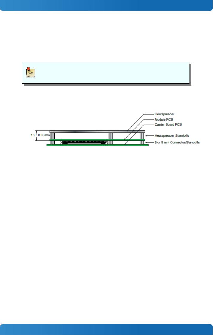
Height
The COM Express® specification defines a module height of 13mm from module PCB bottom to heatspreader top:
Cooling solutions provided from Kontron Europe GmbH for basic sized Computer-on-Modules are 27mm in height from module bottom to Heatsink top.
Universal Cooling solutions to be mounted on the HSP (36099-0000-00-x) are 14.3mm in height for an overall height of 27.3mm from module bottom to Heatsink top.
30
Loading...