


 Loading...
986LCD-M Family
KTD-N0837-B |
Public |
User Manual |
Date: 2012-04-17 Page |
1 of 91 |
User Manual
for the Motherboards:
986LCD-M/mITX |
986LCD-M/mITX BGA |
986LCD-M/Flex
986LCD-M/ATXE |
986LCD-M/ATXP |

986LCD-M Family
KTD-N0837-B |
Public |
User Manual |
Date: 2012-04-17 Page |
2 of 91 |
Document revision history.
Revision |
Date |
By |
Comment |
|
|
|
|
B |
Apr. 17th 2012 |
MLA |
Added information that 986LCD-M/mITX having CF socket no longer |
|
|
|
support PCIe x16 slot. |
|
Jan. 10th 2012 |
|
KTD-00691-Z is now replaced by KTD-N0837-A. |
A |
MLA |
Update UL info for ATXP version. Added BIOS setting: Staggered Spin- |
|
|
|
|
up delay |
Copyright Notice: |
|
|
|
Copyright 2006, KONTRON Technology A/S, ALL RIGHTS RESERVED.
No part of this document may be reproduced or transmitted in any form or by any means, electronically or mechanically, for any purpose, without the express written permission of KONTRON Technology A/S.
Trademark Acknowledgement:
Brand and product names are trademarks or registered trademarks of their respective owners.
Disclaimer:
KONTRON Technology A/S reserves the right to make changes, without notice, to any product, including circuits and/or software described or contained in this manual in order to improve design and/or performance. Specifications listed in this manual are subject to change without notice. KONTRON Technology assumes no responsibility or liability for the use of the described product(s), conveys no license or title under any patent, copyright, or mask work rights to these products, and makes no representations or warranties that these products are free from patent, copyright, or mask work right infringement, unless otherwise specified. Applications that are described in this manual are for illustration purposes only. KONTRON Technology A/S makes no representation or warranty that such application will be suitable for the specified use without further testing or modification.

986LCD-M Family
KTD-N0837-B |
Public |
User Manual |
Date: 2012-04-17 Page |
3 of 91 |
Life Support Policy
KONTRON Technology’s PRODUCTS ARE NOT FOR USE AS CRITICAL COMPONENTS IN LIFE SUPPORT DEVICES OR SYSTEMS WITHOUT EXPRESS WRITTEN APPROVAL OF THE GENERAL MANAGER OF KONTRON Technology A/S.
As used herein:
1.Life support devices or systems are devices or systems which, (a) are intended for surgical implant into body, or (b) support or sustain life and whose failure to perform, when properly used in accordance with instructions for use provided in the labeling, can be reasonably expected to result in significant injury to the user.
2.A critical component is any component of a life support device or system whose failure to perform can be reasonably expected to cause the failure of the life support device or system, or to affect its safety or effectiveness.
KONTRON Technology Technical Support and Services
If you have questions about installing or using your KONTRON Technology Product, check this User’s Manual first – you will find answers to most questions here. To obtain support, please contact your local Distributor or Field Application Engineer (FAE).
Before Contacting Support: Please be prepared to provide as much information as possible:
CPU Board
1.Type.
2.Part-number.
3.Serial Number.
Configuration
1.CPU Type, Clock speed.
2.DRAM Type and Size.
3.BIOS Revision (Find the Version Info in the BIOS Setup).
4.BIOS Settings different than Default Settings (Refer to the BIOS Setup Section).
System
1.O/S Make and Version.
2.Driver Version numbers (Graphics, Network, and Audio).
3.Attached Hardware: Harddisks, CD-rom, LCD Panels etc.
 986LCD-M Family
KTD-N0837-B |
Public |
User Manual |
Date: 2012-04-17 Page |
4 of 91 |
|||
Table of contents: |
|
|
|
|
|||
1. |
INTRODUCTION......................................................................................................................................... |
|
|
7 |
|||
2. |
INSTALLATION PROCEDURE .................................................................................................................. |
|
8 |
||||
|
2.1 |
Installing the board ............................................................................................................................ |
|
|
8 |
||
|
2.2 |
Requirement according to EN60950................................................................................................. |
|
9 |
|||
3. |
SYSTEM SPECIFICATION....................................................................................................................... |
|
10 |
||||
|
3.1 |
Component main data ..................................................................................................................... |
|
10 |
|||
|
3.2 |
Processor support table.................................................................................................................. |
|
13 |
|||
|
3.3 |
System Memory support ................................................................................................................. |
|
14 |
|||
|
3.4 |
System overview .............................................................................................................................. |
|
|
14 |
||
|
3.5 |
986LCD-M Power Distribution & Power State Map....................................................................... |
|
15 |
|||
|
3.6 |
Power Consumption ........................................................................................................................ |
|
17 |
|||
|
3.7 |
986LCD-M Clock Distribution ......................................................................................................... |
|
20 |
|||
4. |
CONNECTOR DEFINITIONS ................................................................................................................... |
|
21 |
||||
|
4.1 |
Connector layout.............................................................................................................................. |
|
|
22 |
||
|
4.1.1 |
986LCD-M/mITX......................................................................................................................... |
|
22 |
|||
|
4.1.2 |
986LCD-M/mITX BGA ................................................................................................................ |
|
23 |
|||
|
4.1.3 |
986LCD-M/Flex........................................................................................................................... |
|
|
24 |
||
|
4.1.4 |
986LCD-M/ATXP ........................................................................................................................ |
|
25 |
|||
|
4.1.5 |
986LCD-M/ATXE ........................................................................................................................ |
|
26 |
|||
|
4.2 |
Power Connector (ATXPWR) .......................................................................................................... |
|
27 |
|||
|
4.3 |
Keyboard and PS/2 mouse connectors ......................................................................................... |
|
28 |
|||
|
4.3.1 Stacked MINI-DIN keyboard and mouse Connector (MSE & KBD)............................................ |
28 |
|||||
|
4.3.2 Keyboard and mouse pin-row Connector (KBDMSE)................................................................. |
|
28 |
||||
|
4.4 |
Display Connectors |
......................................................................................................................... |
|
29 |
||
|
4.4.1 |
CRT Connector (CRT) ................................................................................................................ |
|
29 |
|||
|
4.4.2 |
TV-Out (Optional)........................................................................................................................ |
|
30 |
|||
|
4.4.3 LVDS Flat Panel Connector (LVDS) ........................................................................................... |
|
31 |
||||
|
4.5 |
PCI-Express Connectors ................................................................................................................. |
|
32 |
|||
|
4.5.1 PCI-Express x16/ SDVO connector............................................................................................ |
|
32 |
||||
|
4.5.2 |
PCI-Express x4 |
in a x16 connector ........................................................................................... |
|
33 |
||
|
4.5.3 |
miniPCI-Express connector ........................................................................................................ |
|
35 |
|||
|
4.6 |
Parallel ATA harddisk interface ...................................................................................................... |
|
36 |
|||
|
4.6.1 IDE Hard Disk Connector (IDE_P).............................................................................................. |
|
37 |
||||
|
4.6.2 |
CF Connector (CF) ..................................................................................................................... |
|
38 |
|||
|
4.7 |
Serial ATA harddisk interface ......................................................................................................... |
|
39 |
|||
|
4.7.1 SATA Hard Disk Connector (SATA0, SATA1, SATA2, SATA3)................................................. |
39 |
|||||
|
4.8 |
Printer Port Connector (PRINTER). ................................................................................................ |
|
40 |
|||
 986LCD-M Family
KTD-N0837-B |
Public |
User Manual |
Date: 2012-04-17 Page |
5 of 91 |
|||
|
4.9 |
Serial Ports ....................................................................................................................................... |
|
|
41 |
||
|
4.9.1 |
Com1 (Port1) DB9 Connector..................................................................................................... |
|
41 |
|||
|
4.9.2 |
Com2, Com3 & Com4 Pin Header Connectors. ......................................................................... |
|
41 |
|||
|
4.10 |
Ethernet connectors. |
.................................................................................................................... |
|
42 |
||
|
4.10.1 |
Ethernet connector 1 (ETHER1)................................................................................................. |
|
42 |
|||
|
4.10.2 |
Ethernet connector 2/3 (ETHER2/3)........................................................................................... |
|
43 |
|||
|
4.11 |
Firewire/ IEEE-1394 connectors.................................................................................................. |
|
44 |
|||
|
4.11.1 |
IEEE1394 Connector (IEEE1394_0)........................................................................................... |
|
44 |
|||
|
4.11.2 |
IEEE1394 Connector (IEEE1394_1)........................................................................................... |
|
44 |
|||
|
4.12 |
USB Connector (USB).................................................................................................................. |
|
45 |
|||
|
4.12.1 |
USB Connector 0/2 (USB0/2) ..................................................................................................... |
|
45 |
|||
|
4.12.2 |
USB Connector 4/5 (USB4/5) ..................................................................................................... |
|
46 |
|||
|
4.12.3 |
USB Connector 6/7 (USB6_7) .................................................................................................... |
|
46 |
|||
|
4.13 |
Audio Connector .......................................................................................................................... |
|
|
47 |
||
|
4.13.1 |
Audio Line-in, Line-out and Microphone ..................................................................................... |
|
47 |
|||
|
4.13.2 |
CD-ROM Audio input (CDROM) ................................................................................................. |
|
48 |
|||
|
4.13.3 |
AUDIO Header (AUDIO_HEAD)................................................................................................. |
|
49 |
|||
|
4.14 |
Fan connectors , FAN_CPU and FAN_SYS................................................................................ |
|
50 |
|||
|
4.15 |
The Clear CMOS Jumper, Clr-CMOS. ......................................................................................... |
|
50 |
|||
|
4.16 |
TPM connector (unsupported).................................................................................................... |
|
51 |
|||
|
4.17 |
SPI connector (unsupported)...................................................................................................... |
|
51 |
|||
|
4.18 |
Front Panel connector (FRONTPNL). ......................................................................................... |
|
52 |
|||
|
4.19 |
Feature Connector (FEATURE) ................................................................................................... |
|
53 |
|||
|
4.20 |
PCI Slot.......................................................................................................................................... |
|
|
54 |
||
|
4.20.1 |
PCI |
Slot Connector .................................................................................................................... |
|
54 |
||
|
Signal Description –PCI Slot Connector.................................................................................................... |
|
55 |
||||
|
4.20.2 |
PCI IRQ & INT routing ................................................................................................................ |
|
57 |
|||
5. |
ONBOARD CONNECTORS |
..................................................................................................................... |
|
58 |
|||
6. |
SYSTEM RESSOURCES ......................................................................................................................... |
|
|
59 |
|||
|
6.1 |
Memory map ..................................................................................................................................... |
|
|
59 |
||
|
6.2 |
PCI devices ....................................................................................................................................... |
|
|
60 |
||
|
6.3 |
Interrupt Usage................................................................................................................................. |
|
|
61 |
||
|
6.4 |
I/O Map |
.............................................................................................................................................. |
|
|
62 |
|
|
6.5 |
DMA Channel Usage ........................................................................................................................ |
|
|
63 |
||
7. OVERVIEW OF BIOS FEATURES........................................................................................................... |
|
64 |
|||||
|
7.1 |
System Management BIOS (SMBIOS / DMI) .................................................................................. |
|
64 |
|||
|
7.2 |
Legacy .......................................................................................................................USB Support |
|
|
64 |
||
 986LCD-M Family
KTD-N0837-B |
Public |
User Manual |
Date: 2012-04-17 Page |
6 of 91 |
||
8. BIOS CONFIGURATION / SETUP ........................................................................................................... |
|
65 |
||||
8.1 |
Introduction ...................................................................................................................................... |
|
|
65 |
||
8.2 |
Main Menu......................................................................................................................................... |
|
|
65 |
||
8.3 |
Advanced Menu................................................................................................................................ |
|
|
66 |
||
8.3.1 |
Advanced settings – CPU Configuration..................................................................................... |
|
67 |
|||
8.3.2 |
Advanced settings – IDE Configuration ...................................................................................... |
|
68 |
|||
8.3.3 |
Advanced settings – LAN Configuration ..................................................................................... |
|
70 |
|||
8.3.4 |
FW/IEEE 1394 Configuration...................................................................................................... |
|
71 |
|||
8.3.5 |
Advanced settings – Super IO Configuration.............................................................................. |
|
72 |
|||
8.3.6 |
Advanced settings – Hardware Health Configuration ................................................................. |
|
73 |
|||
8.3.7 |
Advanced settings – Voltage Monitor ......................................................................................... |
|
74 |
|||
8.3.8 |
Advanced settings – ACPI Configuration.................................................................................... |
|
74 |
|||
8.3.9 |
Advanced settings – APM Configuration .................................................................................... |
|
75 |
|||
8.3.10 |
PCI Express Configuration.......................................................................................................... |
|
76 |
|||
8.3.11 |
Advanced settings – Remote Access Configuration................................................................... |
|
77 |
|||
8.3.12 |
Advanced settings – USB Configuration..................................................................................... |
|
78 |
|||
8.3.13 |
Advanced settings – USB Mass Storage Device Configuration.................................................. |
79 |
||||
8.4 |
PCIPnP Menu.................................................................................................................................... |
|
|
80 |
||
8.5 |
Boot Menu......................................................................................................................................... |
|
|
81 |
||
8.5.1 |
Boot – Boot Settings Configuration............................................................................................. |
|
81 |
|||
8.5.2 |
Boot – Boot Device Priority ......................................................................................................... |
|
83 |
|||
8.6 |
Security Menu................................................................................................................................... |
|
|
84 |
||
8.7 |
Chipset Menu.................................................................................................................................... |
|
|
86 |
||
8.7.1 |
Advanced Chipset Settings – North Bridge Chipset Configuration ............................................. |
86 |
||||
8.7.2 |
Advanced Chipset Settings – Video Function Configuration ...................................................... |
87 |
||||
8.7.3 |
Advanced Chipset Settings – SouthBridge Configuration........................................................... |
88 |
||||
8.8 |
Exit Menu |
.......................................................................................................................................... |
|
|
89 |
|
8.9 |
AMI BIOS Beep Codes |
..................................................................................................................... |
|
90 |
||
9. OS SETUP ................................................................................................................................................ |
|
|
|
91 |
||
10. |
WARRANTY .......................................................................................................................................... |
|
|
|
91 |
|

986LCD-M Family
KTD-N0837-B |
Public |
User Manual |
Date: 2012-04-17 Page |
7 of 91 |
1.Introduction
This manual describes the 986LCD-M/Flex, 986LCD-M/ATXP, 986LCD-M/ATXE and 986LCD-M/mITX boards made by KONTRON Technology A/S. The boards will also be denoted 986LCD family if no differentiation is required.
All boards are to be used with the Intel® Core™Duo, Intel® Core™ 2 Duo, Intel® Core™Solo and Celeron® M Processors. These belong to the Intel Yonah and Merom processor families.
Use of this manual implies a basic knowledge of PC-AT hardand software. This manual is focused on describing the 986LCD Board’s special features and is not intended to be a standard PC-AT textbook.
New users are recommended to study the short installation procedure stated in chapter 3 before switching-on the power.
All configuration and setup of the CPU board is either done automatically or by the user in the CMOS setup menus. Except for the CMOS Clear jumper, no jumper configuration is required.
986LCD-M Family
KTD-N0837-B |
Public |
User Manual |
Date: 2012-04-17 Page |
8 of 91 |
2.Installation procedure
2.1Installing the board
To get the board running, follow these steps. In some cases the board shipped from KONTRON Technology has CPU, DDR DRAM and Cooler mounted. In this case Step 2-4 can be skipped.
1. Turn off the power supply.
Warning: Turn off PSU (Power Supply Unit) completely (no mains power connected to the PSU) or leave the Power Connectors unconnected while configuring the board. Otherwise
!components (RAM, LAN cards etc.) might get damaged.
Do not use PSU without 3.3V monitoring watchdog, which is standard feature in ATX PSU. Running the board without 3.3V connected will damage the board after a few minutes.
2.Insert the DDR2 DIMM 240pin DRAM module(s). Important: If only one module is used then use Slot 0. Be careful to push it in the slot(s) before locking the tabs. For a list of approved DDR2 DIMM modules contact your Distributor or FAE (list under preparation). DDR2-667 (PC5400) are supported.
3.Install the processor. The CPU is keyed and will only mount in the CPU socket in one way. Use the handle to open/ close the CPU socket. Intel® Core™Duo, Intel® Core™ 2 Duo, Intel® Core™Solo and Celeron® M Processors are supported, refer to supported processor overview for details.
4.Use heat paste or adhesive pads between CPU and cooler and connect the Fan electrically to the FAN_CPU (J21) connector.
5.Insert all external cables for hard disk, keyboard etc. except for flat panel. A CRT monitor must be connected in order to change CMOS settings to flat panel support. To achieve UDMA-66/100 performance on the IDE interface, 80poled UDMA cables must be used. When using bootable SATA disk, then connect to SATA0 or SATA2 or select in BIOS “ATA/IDE Configuration” = Enhanced.
6.Connect power supply to the board by the ATX/ BTXPWR and 4-pin ATX connectors. For board to operate connection of both the ATX/BTX and 4-pin ATX (12V) connectors are required.
7.Turn on the power on the ATX/ BTX power supply.
8.The PWRBTN_IN must be toggled to start the Power supply; this is done by shorting pins 16 (PWRBTN_IN) and pin 18 (GND) on the FRONTPNL connector (see Connector description). A “normally open” switch can be connected via the FRONTPNL connector.
9.Enter the BIOS setup by pressing the “DEL” key during boot up. Refer to the Software Manual (under preparation) for details on BIOS setup.
Enter Advanced Menu / CPU Configuration / Intel SpeedStep Tech. and select “Maximum Performance”.
Note: To clear all CMOS settings, including Password protection, move the CMOS_CLR jumper (with or without power) for approximately 1 minute. Alternatively turn off power and remove the battery for 1 minute, but be careful to orientate the battery corretly when reinserted.
10. Mounting the board to chassis
Warning: When mounting the board to chassis etc. please notice that the board contains
!components on both sides of the PCB which can easily be damaged if board is handled without reasonable care. A damaged component can result in malfunction or no function at all.
When fixing the Motherboard on a chassis it is recommended using screws with integrated washer and having diameter of ~7mm.
Note: Do not use washers with teeth, as they can damage the PCB mounting hole and may cause short circuits.
986LCD-M Family
KTD-N0837-B |
Public |
User Manual |
Date: 2012-04-17 Page |
9 of 91 |
2.2Requirement according to EN60950
Users of 986LCD boards should take care when designing chassis interface connectors in order to fulfill the EN60950 standard:
When an interface/connector has a VCC (or other power) pin, which is directly connected to a power plane like the VCC plane:
To protect the external power lines of peripheral devices the customer has to take care about:
•That the wires have the right diameter to withstand the maximum available power.
•That the enclosure of the peripheral device fulfils the fire protecting requirements of IEC/EN 60950.
Lithium Battery precautions:
CAUTION! |
|
VORSICHT! |
|
|
|
Danger of explosion if battery is incorrectly |
|
Explosionsgefahr bei unsachgemäßem Austausch |
replaced. |
|
|
|
der Batterie. |
|
|
|
|
Replace only with same or equivalent type |
|
Ersatz nur durch den selben oder einen vom |
|
Hersteller empfohlenen gleichwertigen Typ. |
|
recommended by manufacturer. |
|
|
|
Entsorgung gebrauchter Batterien nach |
|
Dispose of used batteries according |
|
|
|
Angaben des Herstellers. |
|
to the manufacturer’s instructions. |
|
|
|
|
|
|
|
|
ADVARSEL! |
|
ADVARSEL |
Lithiumbatteri – Eksplosionsfare ved fejlagtig |
|
Eksplosjonsfare ved feilaktig skifte av batteri. |
håndtering. |
|
Benytt samme batteritype eller en tilsvarende |
Udskiftning må kun ske med batteri |
|
type anbefalt av apparatfabrikanten. |
af samme fabrikat og type. |
|
Brukte batterier kasseres i henhold til fabrikantens |
Levér det brugte batteri tilbage til leverandøren. |
|
instruksjoner. |
|
|
|
VARNING |
|
VAROITUS |
|
|
|
Explosionsfara vid felaktigt batteribyte. |
|
Paristo voi räjähtää, jos se on virheellisesti |
|
asennettu. |
|
Använd samma batterityp eller en ekvivalent |
|
|
|
Vaihda paristo ainoastaan laltevalmistajan |
|
typ som rekommenderas av apparattillverkaren. |
|
|
|
suosittelemaan |
|
Kassera använt batteri enligt fabrikantens |
|
|
|
tyyppiin. Hävitä käytetty paristo valmistajan |
|
instruktion. |
|
|
|
ohjeiden |
|
|
|
|
|
|
mukaisesti. |
|
|
|

986LCD-M Family
KTD-N0837-B |
Public |
User Manual |
Date: 2012-04-17 Page |
10 of 91 |
3.System specification
3.1Component main data
The table below summarises the features of the 986LCD-M/mITX, 986LCD-M/Flex, 986LCD-M/ATXP and 986LCD-M/ATXE embedded motherboards.
Form factor |
986LCD-M/mITX: mini ITX (170.18millimeters by 170.18millimeters) |
|
|
986LCD-M/Flex: Flex-ATX (190,50millimeters by 228,60millimeters) |
|
|
986LCD-M/ATXP: ATX (190,50millimeters by 304,00millimeters) |
|
|
986LCD-M/ATXE: ATX (190,50millimeters by 304,00millimeters) |
|
Processor |
• |
Support for Intel® Core™Duo, Intel® Core™ 2 Duo, Intel® Core™Solo and Celeron® |
|
|
M Processors in 478pin Micro-FCPGA package with up to 667MHz system bus and |
|
|
1/2/4MB internal cache. |
|
• Yonah (65 nanometer) and Merom (65 nanometer) family processors. |
|
Memory |
• |
2 pcs DDR2 DIMM 240pin DRAM sockets. |
|
• Support for DDR 400/533/667 (PC3200/PC4200/PC5300) |
|
|
• Support system memory from 256MB up to 3GB (2+1GB type Samsung PC5300U- |
|
|
|
M378T5663AZ3-CE6 + PC5300U_M378T2953CZ3-CE6). |
|
• |
ECC not supported |
Chipset |
Intel 945GM Chipset consisting of: |
|
|
• Intel® 82945G Graphics and Memory Controller Hub (GMCH) |
|
|
• Intel® ICH7R I/O Controller Hub (ICH7R) |
|
|
• 8 Mbit Firmware Hub (FWH) |
|
Video |
• |
Intel® Integrated Graphics Engine (Generation 3.5) |
|
• Intel® Graphics Media Accellerator 950 (Intel® GMA 950) |
|
|
• Dynamic Video Memory Technology (DVMT) 3.0, 160MB/224MB when using SDRAM |
|
|
|
256MB/512MB min. (System memory is allocated when it is needed dynamically). |
|
• Analog Display Support CRT, 400-MHz integrated RAMDAC with support for analogue |
|
|
|
monitors up to 2048x1536 at 75 Hz |
|
• Single or dual channel 18bit LVDS panel support (OpenLDI/ SPWG) up to UXGA |
|
|
|
(1600x1200) panel resolution. Interlaced Display output support. |
|
|
NOTE: Support of 24bit OpenLDI/ SPWG panels are not officially supported by Intel®, |
|
|
but is supported by the 986LCD series boards by Kontron. Kontron intends to continue |
|
|
to provide 24bit OpenLDI/ SPWG panel support even if Intel® withdraws this from the |
|
|
chipset. |
|
• TV-Out option, NTSC/ PAL, three integrated 10-bit DACs, Macrovision support. |
|
|
|
IMPORTANT: If the TV-Out option is available then you must make agreement with |
|
|
Macrovision (http://www.macrovision.com/) about lincence fee. Only Macrovision (not |
|
|
Kontron) can determine the actual licence fee which depends on the application. |
|
• Serial Digital Video Out (SDVO) ports (2 channels) for additional CRT, LVDS panel, |
|
|
|
DVI, TV-Out and/or HDMI support via Advanced Digital Display 2 (ADD2) cards or |
|
|
Media Expansion Cards. |
|
|
Dual independent pipe support, Mirror and Dual independent display support. Dual |
|
|
Monitor support with combinations of LVDS interface, SDVO port, CRT and TV-Out. |
Audio |
Audio, 7.1 and 7.2 Channel High Definition Audio Codec using the Realtek ALC882 codec |
|
|
• |
Line-out |
|
• |
Line-in |
|
• Surround output: SIDE, LFE, CEN, BACK and FRONT |
|
|
• |
Microphone: MIC1 |
|
• |
CDROM in |
|
• |
SPDIF Interface |
|
Onboard speaker |
|
|
|
(continues) |
986LCD-M Family
KTD-N0837-B |
Public |
User Manual |
Date: 2012-04-17 Page |
11 of 91 |
I/O Control |
Winbond W83627THF LPC Bus I/O Controller |
||
Peripheral |
• |
Four USB 2.0 ports on I/O area |
|
interfaces |
• |
Four USB 2.0 ports on internal pinrows |
|
|
• One IEEE1394a Firewire port on I/O area (IEEE1394a-2000 OHCI controller) |
||
|
• One IEEE1394a Firewire port on internal pinrow (IEEE1394a-2000 OHCI controller) |
||
|
• Four Serial ports (RS232) |
||
|
• One Parallel port, SPP/EPP/ECP |
||
|
• Four Serial ATA 300 IDE interfaces |
||
|
• Two Parallel ATA IDE interfaces with UDMA 33, ATA-66/100 support |
||
|
• CF (only 986LCD-M/mITX PN 810200 and PN 810203). |
||
|
• PS/2 keyboard and mouse ports |
||
LAN |
• |
986LCD-M/mITX: 3x 10/100/1000Mbits/s LAN using Realtek RTL8111B controllers |
|
Support |
• |
986LCD-M/Flex: 2x 10/100/1000Mbits/s LAN using Realtek RTL8111B controllers |
|
|
• 986LCD-M/ATXP: 3x 10/100/1000Mbits/s LAN using Realtek RTL8111B controllers |
||
|
• 986LCD-M/ATXE: 2x 10/100/1000Mbits/s LAN using Realtek RTL8111B controllers |
||
|
• PXE netboot supported. Wake On LAN (WOL) supported. |
||
BIOS |
• |
Kontron Technology / AMI BIOS (core version) |
|
|
• Support for Advanced Configuration and Power Interface (ACPI 3.0), Plug and Play |
||
|
|
o |
Suspend To Ram |
|
|
o |
Suspend To Disk |
|
|
o |
Intel Speed Step |
|
• Secure CMOS/ OEM Setup Defaults |
||
|
• “Always On” BIOS power setting |
||
|
• RAID Support (RAID modes 0, 1, 5 and 10) (for Linux O/S only RAID 0 and 1) |
||
Expansion |
• |
PCI Bus routed to PCI slot(s) (PCI Local Bus Specification Revision 2.3) |
|
Capabilities |
|
o 986LCD-M/mITX: 1 slot PCI 2.3, 32 bits, 33 MHz, 5V compliant |
|
|
|
o 986LCD-M/Flex: 2 slots PCI 2.3, 32 bits, 33 MHz, 5V compliant |
|
|
|
o 986LCD-M/ATXP: 6 slots PCI 2.3, 32 bits, 33 MHz, 5V compliant |
|
|
|
o 986LCD-M/ATXE: 5 slots PCI 2.3, 32 bits, 33 MHz, 5V compliant |
|
|
• PCI-Express bus routed to PCI Express slot(s) (PCI Express 1.0a) |
||
|
|
o 986LCD-M/mITX: 1 slot PCI-Express x16 (except PN 810200-45xx-R18 and PN |
|
|
|
|
810203-45xx-R18 and later versions). |
|
|
o 986LCD-M/Flex: 1 slot PCI-Express x16, 1 slot PCI-Express x4 |
|
|
|
o 986LCD-M/ATXP: 1 slot PCI-Express x16 |
|
|
|
o 986LCD-M/ATXE: 1 slot PCI-Express x16, 1 slot PCI-Express x4 |
|
|
• Mini PCI-Express routed to mini PCI-Express connector |
||
|
|
Support for Mini PCI-Express modules with no components on backside. |
|
|
|
o 986LCD-M/mITX: 1 slot mini PCI-Express x1 |
|
|
|
o |
986LCD-M/Flex: None |
|
|
o 986LCD-M/ATXP: 1 slot mini PCI-Express x1 |
|
|
|
o |
986LCD-M/ATXE: None |
|
• SMBus routed to FEATURE, PCI slot, PCI Express and mini-PCI Express connectors |
||
|
• LPC Bus routed to TPM connector |
||
|
• DDC Bus routed to LVDS and CRT connector |
||
|
• |
8 x GPIOs (General Purpose I/Os) routed to FEATURE connector |
|
Hardware |
• |
Smart Fan control system, support Thermal® and Speed® cruise for three onboard |
|
Monitor |
|
Fan control connectors: FAN_CPU, FAN_SYS and FEATURE |
|
Subsystem |
• |
Three thermal inputs: CPU die temperature, System temperature and External |
|
|
|
temperature input routed to FEATURE connector. (Precision +/- 7ºC) |
|
|
• |
Voltage monitoring |
|
|
• |
Intrusion detect input |
|
|
SMI violations (BIOS) on HW monitor not supported. Supported by API (Windows). |
||
|
|
|
(continues) |

986LCD-M Family
KTD-N0837-B |
Public |
User Manual |
Date: 2012-04-17 Page |
12 of 91 |
Operating |
• |
Win2000 |
Systems |
• |
WinXP |
Support |
• |
Win2003 |
|
• |
WinXP Embedded |
|
• WinCE.net (limitations may apply) |
|
|
• Linux: Feodora Core 5, Suse 10.01 (limitations may apply) |
|
Environmental |
Operating: |
|
Conditions |
0°C – 60°C operating temperature (forced cooling). It is the customer’s responsibility |
|
|
to provide sufficient airflow around each of the components to keep them within |
|
|
allowed temperature range. |
|
|
10% - 90% relative humidity (non-condensing) |
|
|
Storage: |
|
|
-20°C – 70°C |
|
|
5% - 95% relative humidity (non-condensing) |
|
|
Electro Static Discharge (ESD) / Radiated Emissions (EMI): |
|
|
All Peripheral interfaces intended for connection to external equipment are ESD/ EMI |
|
|
protected. |
|
|
EN 61000-4-2:2000 ESD Immunity |
|
|
EN55022:1998 class B Generic Emission Standard. |
|
|
Safety: |
|
|
UL 60950-1:2003, First Edition |
|
|
CSA C22.2 No. 60950-1-03 1st Ed. April 1, 2003 |
|
|
Product Category: Information Technology Equipment Including Electrical Business |
|
|
Equipment |
|
|
Product Category CCN: NWGQ2, NWGQ8 |
|
|
File number: E194252 |
|
|
Theoretical MTBF: |
|
|
160.000/91.000 hours @ 40/60ºCCalculation based on Telcordia SR-332 method. |
|
|
Restriction of Hazardeous Substances (RoHS): |
|
|
All boards in the 986LCD-M family are RoHS compliant. |
|
|
Capacitor utilization: |
|
|
No Tantal capacitors used. |
|
|
Only Japanese brand Aluminium capacitors rated for 100ºC is used. |
|
Battery |
Exchangeable 3.0V Lithium battery for onboard Real Time Clock and CMOS RAM. |
|
|
Manufacturer Panasonic / PN CR2032NL/LE, CR-2032L/BE or CR-2032L/BN. |
|
|
Expected minimum 5 years retention varies depending on temperature, actual |
|
|
application on/off rate and variation within chipset and other components. |
|
|
Approximately current draw is 2.2µA (no PSU connected). |
|
|
CAUTION: Danger of explosion if the battery is incorrectly replaced. Replace |
|
|
only with the same or equivalent type recommended by the manufacturer. |
|
|
Dispose of used batteries according to the manufacturer’s instructions. |
|

986LCD-M Family
KTD-N0837-B |
Public |
User Manual |
Date: 2012-04-17 Page |
13 of 91 |
3.2Processor support table.
The 986LCD-M/mITX, /Flex, /ATXP and /ATXE are designed to support the PGA (478 pins) processors:
Intel® Core™ 2 Duo Mobile Processor, Merom 65 nm process, FSB 667MHz with 4 MB L2 cache Intel® Core™ Duo Processor, Yonah 65 nm process, FSB 667MHz with 2 MB L2 cache
Intel® Core™ Solo Processor, Yonah 65 nm process, FSB 667MHz with 2 MB L2 cache Celeron® M Processor, Yonah 65 nm process, FSB 533MHz with 1 MB L2 cache
Processor Brand |
|
Clock |
|
|
Processor |
|
|
sSpec |
|
|
Thermal |
|
Embedded |
|
|
|
|
|
|
|
|
|
|
||||||
|
|
Speed |
|
|
Number |
|
|
no. |
|
|
Guideline |
|
|
|
Intel® Core™ 2 Duo, 65nm, 4 MB L2 |
|
2.33 GHz |
|
|
T7600 |
|
|
SL9SD |
|
|
34.0 W |
|
No |
|
|
|
2.16 GHz |
|
|
T7400 |
|
|
SL9SE |
|
|
34.0 W |
|
Yes |
|
|
|
2.16 GHz |
|
|
T7400 |
|
|
SLGFJ |
|
|
34.0 W |
|
Yes |
|
|
|
|
|
|
|
|
|
|
|
|
|
|
|
|
|
|
2.00 GHz |
|
|
T7200 |
|
|
SL9SF |
|
|
34.0 W |
|
No |
|
|
|
|
|
|
|
|
|
|
|
|
|
|
|
|
|
|
1.83 GHz |
|
|
T5600 |
|
|
SL9SG |
|
|
34.0 W |
|
No |
|
|
|
|
|
|
|
|
|
|
|
|
|
|
|
|
|
|
1.66 GHz |
|
|
T5500 |
|
|
SL9SH |
|
|
34.0 W |
|
No |
|
|
|
|
|
|
|
|
|
|
|
|
|
|
|
|
Intel® Core™ Duo, 65nm, 2 MB L2 |
|
2.16 GHz |
|
|
T2600 |
|
|
SL8VN |
|
|
31.0 W |
|
No |
|
|
|
2.00 GHz |
|
|
T2500 |
|
|
SL8VP |
|
|
31.0 W |
|
Yes |
|
|
|
|
|
|
|
|
|
|
|
|
|
|
|
|
|
|
1.83 GHz |
|
|
T2400 |
|
|
SL8VQ |
|
|
31.0 W |
|
No |
|
|
|
|
|
|
|
|
|
|
|
|
|
|
|
|
|
|
1.66 GHz |
|
|
T2300 |
|
|
SL8VR |
|
|
31.0 W |
|
No |
|
|
|
|
|
|
|
|
|
|
|
|
|
|
|
|
Intel® Core™ Solo, 65nm, 2 MB L2 |
|
1.83 GHz |
|
|
T1400 |
|
|
SL92V |
|
|
27.0 W |
|
No |
|
|
|
1.66 GHz |
|
|
T1300 |
|
|
SL8VY |
|
|
27.0 W |
|
No |
|
|
|
|
|
|
|
|
|
|
|
|
|
|
|
|
Celeron® M, 65nm, 1 MB L2 |
|
1.86 GHz |
|
440 |
|
|
SL9KW |
|
|
27.0W |
|
Yes |
|
|
|
|
1.73 GHz |
|
530 |
|
|
SL9VA |
|
|
27.0 W |
|
No |
|
|
|
|
|
|
|
|
|
|
|
|
|
|
|
|
|
|
|
1.73 GHz |
|
530 |
|
|
SLA2G* |
|
|
27.0 W |
|
No |
|
|
|
|
|
|
|
|
|
|
|
|
|
|
|
|
|
|
|
1.73 GHz |
|
430 |
|
|
SL92F |
|
|
27.0 W |
|
No |
|
|
|
|
|
|
|
|
|
|
|
|
|
|
|
|
|
|
|
1.60 GHz |
|
420 |
|
|
SL8VZ |
|
|
27.0W |
|
No |
|
|
|
|
|
|
|
|
|
|
|
|
|
|
|
|
|
|
|
1.46 GHz |
|
410 |
|
|
SL8W2 |
|
|
27.0 W |
|
No |
|
|
|
|
|
|
|
|
|
|
|
|
|
|
|
|
|
986LCD-M/mITX(BGA) w Core Duo |
|
1.66 GHz |
|
|
L2400 |
|
|
SL8VW |
|
|
15W |
|
Yes |
|
986LCD-M/mITX(BGA) w Celeron M |
|
1.06 GHz |
|
- |
|
- |
|
|
5.5W |
|
- |
|
||
1MB L2 |
|
|
|
|
|
|
|
|||||||
|
|
|
|
|
|
|
|
|
|
|
|
|
|
|
*) For the SLA2G and in general only socket M version is supported.
986LCD-M Family
KTD-N0837-B |
Public |
User Manual |
Date: 2012-04-17 Page |
14 of 91 |
3.3System Memory support
The 986LCD-M boards have two onboard DDR2 DIMM sockets and support the following memory features:
•1.8V (only) 240-pin DDR2 SDRAM DIMMs with gold-plated contacts
•Supports Single- / Dual channel DDR2 SDRAM
•Supports 256 Mbit, 512 Mbit and 1 Gbit technologies for x8 ans x16 width devices 256MB, 512MB and 1GB Single Rank Modules supported
512MB, 1GB and 2GB Dual Rank Modules supported
•Maximum of 3 Gbytes (2GB + 1GB) based on Samsung PC5300U-M378T5663AZ3-CE6 + PC5300U_M378T2953CZ3-CE6).
•Supports 400 MHz (PC3200) , 533 MHz (PC4200), and 667 MHz (PC5400) DDR2 devices
•64-bit data interface (ECC not supported)
The installed DDR2 SDRAM should support the Serial Presence Detect (SPD) data structure. This allows the BIOS to read and configure the memory controller for optimal performance. If non-SPD memory is used, the BIOS will attempt to configure the memory settings, but performance and reliability may be impacted.
Important: If only one module is used then use Slot 0.
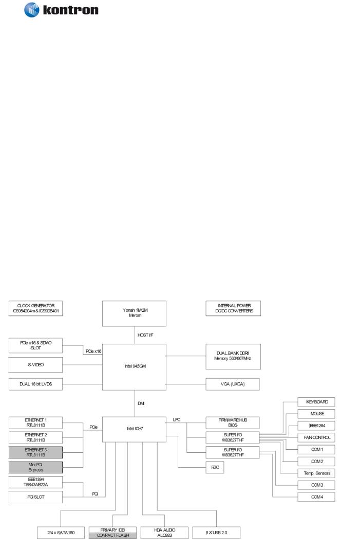
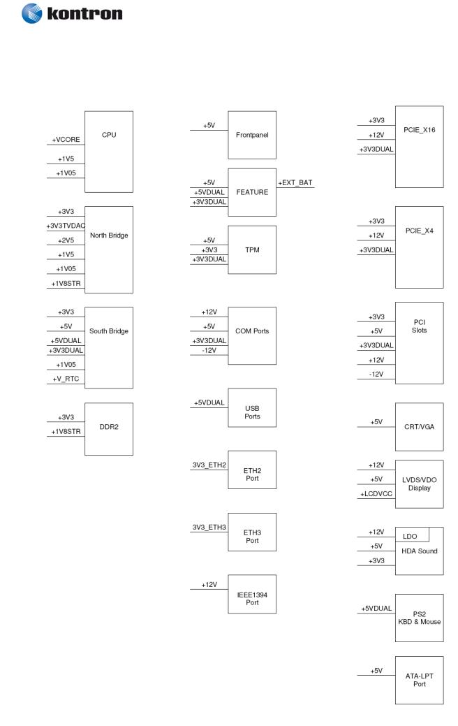
3.4System overview
The block diagram below shows the architecture and main components of the 986LCD boards. The two key components on the board are the Intel® 945GM and Intel® ICH7R Embedded Chipsets.
Components shown shaded are optional depending on board type (986LCD-M/mITX, /Flex, /ATXP or /ATXE) and variants of the board.
986LCD-M Family
KTD-N0837-B |
Public |
User Manual |
Date: 2012-04-17 Page |
15 of 91 |
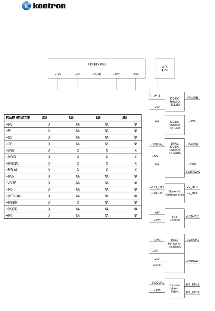
3.5 986LCD-M Power Distribution & Power State Map
(continues)
986LCD-M Family
KTD-N0837-B |
Public |
User Manual |
Date: 2012-04-17 Page |
16 of 91 |
986LCD-M Family
KTD-N0837-B |
Public |
User Manual |
Date: 2012-04-17 Page |
17 of 91 |
3.6Power Consumption
In order to ensure safe operation of the board, the ATX power supply must monitor the supply voltage and shut down if the supplies are out of range – refer to the hardware manual for actual power specification.
The 986LCD-M board is powered through the ATX connector and the additional 12V separate supply for CPU as specified in the ATX specification; besides this the power supplied to the board must be within the ATX specification.
The requirements to the supply voltages are as follows:
Supply |
Min |
Max |
Note |
Vcc3 |
3.135V |
3.465V |
Should be ±5% for compliance with the ATX specification |
|
|
|
|
Vcc |
4.75V |
5.25V |
Should be ±5% for compliance with the ATX specification |
+12V |
11.4V |
12.6V |
Should be ±5% for compliance with the ATX specification |
–12V |
–13.2V |
–10.8V |
Should be ±10% for compliance with the ATX specification |
-5V |
-5,50V |
-4.5V |
Not required for the 986LCD-M/mITX board |
5VSB |
4.75V |
–5.25V |
Should be ±5% for compliance with the ATX specification |
|
|
|
|
Test system configuration
The following items are used in the test setup:
1.986LCD-M board equipped with CPU, RAM and 12V active cooler if required
2.ATX PSU
3.CRT, PS/2 keyboard & mouse and HD
4.Tektronix TDS 7404, P6345 probes
5.Fluke Current Probe 80i-100S AC/DC
|
|
|
|
ATX supplies |
|
||
986LCD-M |
PSU |
||||||
|
|
|
|
|
|||
|
|
|
|
|
|||
Incl. CRT, PS/2 |
|
|
|
Gnd |
|||
|
|
|
|
||||
|
|||||||
|
|
|
|
||||
|
|
|
|
|
|
||
Kbd/Mse and HD |
|
Current |
|
|
|||
|
|
Probe |
|
|
|||
|
|
|
|
|
|
|
|
|
|
|
|
|
|
|
|
Tektronix TDS 7404
Note: |
The Power consumption of CRT, Fan and HD is not included. |
Test results:
The power consumption of the 986LCD-M Board is measured under: 1- DOS, idle, mean
2- WindowsXP, Running 3DMARK & CPU BURN, mean
3- WindowsXP, Running 3DMARK & CPU BURN, peak
4- S1, mean
5- S3, mean
6- S4, mean
7- Inrush, peak

986LCD-M Family
KTD-N0837-B |
Public |
User Manual |
Date: 2012-04-17 Page |
18 of 91 |
986LCD-M/mITX with Core Duo (T2500) & 1GB DDR2 Ram test results:
Test |
Supply |
Current draw |
Power consumption |
DOS, Idle, mean |
+12V |
0.88A |
10.56W |
|
+5V |
1.48A |
7.4W |
|
+3V3 |
1.22A |
4.03W |
|
-12V |
0.05A |
0.6W |
|
5VSB |
0A |
0W |
|
|
Total |
22.59W |
WinXP, 3DMARK2000 & |
+12V |
2.34A |
28.08W |
CPUBURN, mean |
+5V |
1.73A |
8.65W |
|
+3V3 |
1.22A |
4.03W |
|
-12V |
0.05A |
0.6W |
|
5VSB |
0A |
0W |
|
|
Total |
41.36W |
WinXP, 3DMARK2000 & |
+12V |
2.67A |
32.04W |
CPUBURN, peak |
+5V |
2.48A |
12.4W |
|
+3V3 |
1.28A |
4.22W |
|
-12V |
0.08A |
0.96W |
|
5VSB |
0A |
0W |
|
|
Total |
49.62W |
S1, mean |
+12V |
0.83A |
9.96W |
|
+5V |
1.17A |
5.85W |
|
+3V3 |
1.21A |
3.99W |
|
-12V |
0.03A |
0.36W |
|
5VSB |
0A |
0W |
|
|
Total |
20.16W |
S3, mean |
+12V |
0A |
0W |
|
+5V |
0A |
0W |
|
+3V3 |
0A |
0W |
|
-12V |
0.03A |
0.36W |
|
5VSB |
0.64A |
3.68W |
|
|
Total |
4.04W |
S4, mean |
+12V |
0A |
0W |
|
+5V |
0A |
0W |
|
+3V3 |
0A |
0W |
|
+-12V |
0A |
0W |
|
5VSB |
0.64A |
3.2W |
|
|
Total |
3.2W |
Inrush, peak |
+12V |
5.08A |
|
|
+5V |
2.48A |
|
|
+3V3 |
3.52A |
|
|
-12V |
0.3A |
|
|
5VSB |
2.92A |
|

986LCD-M Family
KTD-N0837-B |
Public |
User Manual |
Date: 2012-04-17 Page |
19 of 91 |
986LCD-M/mITX with w/1.06GHz Celeron M 512MB test results:
Test |
Supply |
Current draw |
Power consumption |
DOS, Idle, mean |
+12V |
0.36A |
4.32W |
|
+5V |
1.37A |
6.85W |
|
+3V3 |
1.31A |
4.323W |
|
-12V |
0A |
0W |
|
5VSB |
0A |
0W |
|
|
Total |
15.493W |
WinXP, 3DMARK2000 & |
+12V |
0.4A |
4.8W |
CPUBURN, mean |
+5V |
1.47A |
7.35W |
|
+3V3 |
1.54A |
5.08W |
|
-12V |
0A |
0W |
|
5VSB |
0A |
0W |
|
|
Total |
17.232W |
WinXP, 3DMARK2000 & |
+12V |
0.61A |
7.32W |
CPUBURN, peak |
+5V |
2.1A |
10.5W |
|
+3V3 |
1.64A |
5.41W |
|
-12V |
0A |
0W |
|
5VSB |
0A |
0W |
|
|
Total |
23.232W |
S1, mean |
+12V |
0.25A |
3W |
|
+5V |
1.05A |
5.25W |
|
+3V3 |
0.75A |
2.48W |
|
-12V |
0A |
0W |
|
5VSB |
0A |
0W |
|
|
Total |
10.73W |
S3, mean |
+12V |
0A |
0W |
|
+5V |
0A |
0W |
|
+3V3 |
0A |
0W |
|
-12V |
0A |
0W |
|
5VSB |
0.18A |
0.9W |
|
|
Total |
0.9W |
S4, mean |
+12V |
0A |
0W |
|
+5V |
0A |
0W |
|
+3V3 |
0A |
0W |
|
+-12V |
0A |
0W |
|
5VSB |
0.18A |
0.9W |
|
|
Total |
0.9W |
Inrush, peak |
+12V |
1.54A |
|
|
+5V |
1.02A |
|
|
+3V3 |
1.2A |
|
|
-12V |
0.09A |
|
|
5VSB |
3.5A |
|

986LCD-M Family
KTD-N0837-B |
Public |
User Manual |
Date: 2012-04-17 Page |
20 of 91 |
3.7986LCD-M Clock Distribution
986LCD-M Family
KTD-N0837-B |
Public |
User Manual |
Date: 2012-04-17 Page |
21 of 91 |
4.Connector Definitions
The following sections provide pin definitions and detailed description of all on-board connectors.
.
The connector definitions follow the following notation:
Column |
|
Description |
|
|
|
||
name |
|
|
|
Pin |
|
Shows the pin-numbers in the connector. The graphical layout of the connector definition |
|
|
|
tables is made similar to the physical connectors. |
|
Signal |
|
The mnemonic name of the signal at the current pin. The notation “XX#” states that the signal |
|
|
|
“XX” is active low. |
|
Type |
|
AI: |
Analog Input. |
|
AO: |
Analog Output. |
|
|
I: |
Input, TTL compatible if nothing else stated. |
|
|
IO: |
Input / Output. TTL compatible if nothing else stated. |
|
|
IOT: |
Bi-directional tristate IO pin. |
|
|
IS: |
Schmitt-trigger input, TTL compatible. |
|
|
IOC: |
Input / open-collector Output, TTL compatible. |
|
|
NC: |
Pin not connected. |
|
|
O: |
Output, TTL compatible. |
|
|
OC: |
Output, open-collector or open-drain, TTL compatible. |
|
|
OT: |
Output with tri-state capability, TTL compatible. |
|
|
LVDS: |
Low Voltage Differential Signal. |
|
|
PWR: |
Power supply or ground reference pins. |
|
|
|
|
|
|
|
Ioh: Typical current in mA flowing out of an output pin through a grounded load, while the |
|
|
|
output voltage is > 2.4 V DC (if nothing else stated). |
|
|
|
Iol: Typical current in mA flowing into an output pin from a VCC connected load, while the |
|
|
|
output voltage is < 0.4 V DC (if nothing else stated). |
|
Pull U/D |
|
On-board pull-up or pull-down resistors on input pins or open-collector output pins. |
|
Note |
|
Special remarks concerning the signal. |
|
The abbreviation TBD is used for specifications which are not available yet or which are not sufficiently specified by the component vendors.
986LCD-M Family
KTD-N0837-B |
Public |
User Manual |
Date: 2012-04-17 Page |
22 of 91 |
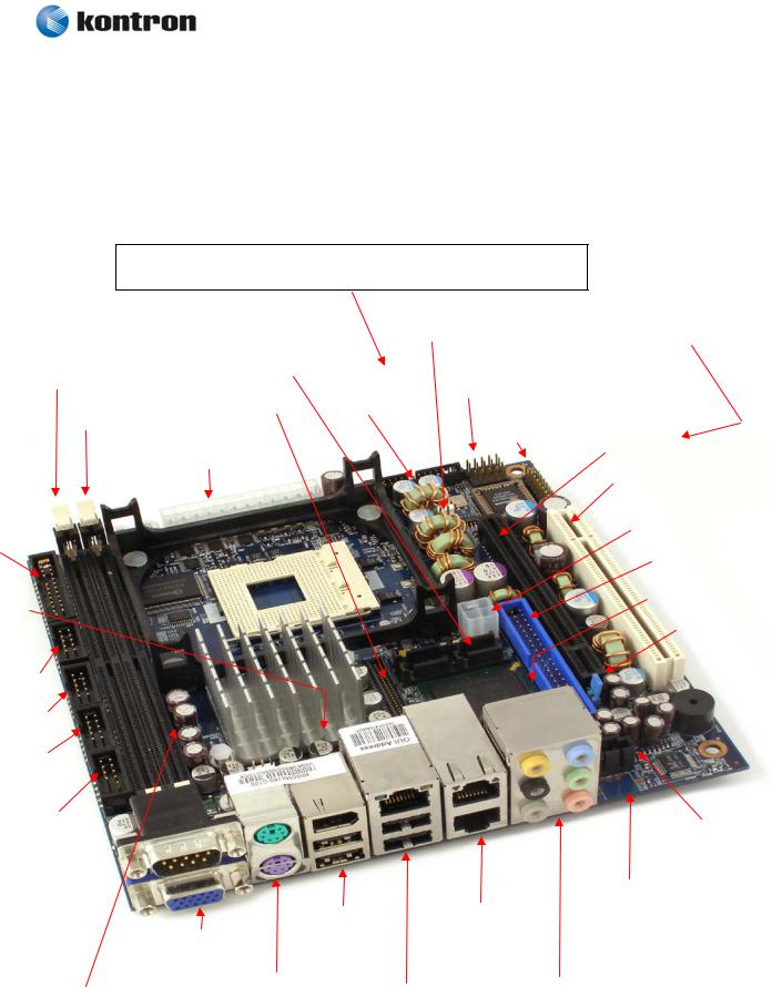
4.1Connector layout
4.1.1986LCD-M/mITX
Mini-PCIe (backside of 986LCD-M/mITX)
(Support for modules with no components mounted on backside).
|
|
|
|
|
|
|
|
|
|
|
|
|
|
|
|
|
|
|
|
|
|
|
|
|
|
|
|
|
|
|
|
|
|
|
|
|
|
|
CF * (backside of |
|
||||||||||
|
|
|
|
|
|
|
|
|
|
|
|
|
|
|
|
|
|
|
|
|
|
|
|
|
|
FAN_CPU |
|
|
|
|
|
|
|
|
|
|||||||||||||||
|
|
|
|
|
|
|
|
|
|
|
|
|
|
|
|
|
|
|
|
|
|
|
|
|
|
|
|
|
|
|
|
|
|
|
986LCD-M/mITX) |
|
||||||||||||||
|
|
|
|
|
|
|
|
|
|
|
|
|
|
|
|
|
SATA3 SATA1 |
|
|
|
|
|
|
|
|
|
|
|
||||||||||||||||||||||
|
|
|
|
|
|
|
|
|
|
|
|
|
|
|
|
|
|
|
|
|
|
|
|
|
|
|
|
|
|
|
|
|
|
|
|
|
|
|
|
|
||||||||||
|
|
|
|
|
|
|
|
|
|
|
|
|
|
|
|
|
|
|
|
|
|
|
|
|
|
|
|
|
|
|
|
|
|
|
|
|
|
|
|
|||||||||||
|
|
|
|
|
|
|
|
|
|
|
|
|
|
|
|
|
|
|
|
|
|
|
|
|
|
|
|
|
|
|
|
|
|
|
|
|
|
|
|
|
|
|
|
|||||||
|
|
|
|
|
|
|
|
|
|
|
|
|
|
|
|
|
SATA2 SATA0 |
|
|
|
|
|
|
|
|
|
|
|
|
|
|
|
|
|
|
|
|
|
|
|
||||||||||
|
|
|
|
DDR2 SLOT 1 |
|
|
|
|
|
|
|
|
SPI |
|
|
|
|
|
|
|
|
|
|
|
|
|
|
|
|
|||||||||||||||||||||
|
|
|
|
|
|
|
|
|
|
|
|
|
|
|
|
|
|
|
|
|
|
|
|
|
|
|
|
|
|
|
|
|
|
|
||||||||||||||||
|
|
|
|
|
|
|
|
|
|
|
|
|
|
|
|
|
|
|
|
|
|
|
|
|
|
|
|
|
IEEE1394 1 |
|
|
|
|
|
|
|
|
|
|
|
|
|
|
|
|
|||||
|
|
|
|
|
|
|
|
|
|
|
|
|
|
|
|
LVDS |
|
|
|
|
FEATURE |
|
|
|
|
|
|
|
|
|
|
|
|
|
|
|
|
|
||||||||||||
|
|
|
|
|
|
|
|
|
DDR2 SLOT 0 |
|
|
|
|
|
|
|
|
|
|
|
|
|
|
|
|
|
|
|
|
|
|
|
|
|
|
|
|
|
||||||||||||
|
|
|
|
|
|
|
|
|
|
|
|
|
|
|
|
|
|
|
|
|
|
|
|
|
|
|
|
|
|
|
|
TPM |
|
PCIe x16 / |
|
|
|
|
|
|
||||||||||
|
|
|
|
|
|
|
|
|
|
|
|
|
|
|
|
|
|
|
|
|
|
|
|
|
|
|
|
|
|
|
|
|
|
|
|
|
|
|
||||||||||||
|
|
|
|
|
|
|
|
|
|
|
|
|
|
|
|
|
|
|
|
|
|
|
|
|
|
|
|
|
|
|
|
|
|
|
|
SDVO * |
|
|
|
|
|
|
||||||||
|
|
|
|
|
|
|
|
|
|
|
|
ATX/ BTXPWR |
|
|
|
|
|
|
|
|
|
|
|
|
|
|
|
|
|
|
|
|
|
|
|
|
||||||||||||||
|
|
|
|
|
|
|
|
|
|
|
|
|
|
|
|
|
|
|
|
|
|
|
|
|
|
|
|
|
|
|
|
|
|
|
|
|
|
|
|
|
|
|
||||||||
|
|
|
|
|
|
|
|
|
|
|
|
|
|
|
|
|
|
|
|
|
|
|
|
|
|
|
|
|
|
|
|
|
|
|
|
|
|
|
|
|
|
|
|
|
|
|
|
|
||
|
|
|
|
|
|
|
|
|
|
|
|
|
|
|
|
|
|
|
|
|
|
|
|
|
|
|
|
|
|
|
|
|
|
|
|
|
|
|
PCI SLOT |
|
|
|
|
|
||||||
|
|
|
|
|
|
|
|
|
|
|
|
|
|
|
|
|
|
|
|
|
|
|
|
|
|
|
|
|
|
|
|
|
|
|
|
|
|
|
|
|
|
|
|
|
|
|
|
|
||
|
|
|
|
|
|
|
|
|
|
|
|
|
|
|
|
|
|
|
|
|
|
|
|
|
|
|
|
|
|
|
|
|
|
|
|
|
|
|
|
|
|
|
||||||||
|
|
|
|
|
|
|
|
|
|
|
|
|
|
|
|
|
|
|
|
|
|
|
|
|
|
|
|
|
|
|
|
|
|
|
|
|
|
|
|
|
ATX+12V |
|
||||||||
FRONTPNL |
|
|
|
|
|
|
|
|
|
|
|
|
|
|
|
|
|
|
|
|
|
|
|
|
|
|
|
|
|
|
|
|
|
|
||||||||||||||||
|
|
|
|
|
|
|
|
|
|
|
|
|
|
|
|
|
|
|
|
|
|
|
|
|
|
|
|
|
|
|
|
|
|
|
|
|
|
|
|
|
||||||||||
|
|
|
|
|
|
|
|
|
|
|
|
|
|
|
|
|
|
|
|
|
|
|
|
|
|
|
|
|
|
|
|
|
|
|
|
|
|
|
|
|
||||||||||
|
|
|
|
|
|
|
|
|
|
|
|
|
|
|
|
|
|
|
|
|
|
|
|
|
|
|
|
IDE_P |
|
|
|
|
||||||||||||||||||
|
|
|
|
|
|
|
|
|
|
|
|
|
|
|
|
|
|
|
|
|
|
|
|
|
|
|
|
|
|
|
|
|
|
|
|
|
|
|
|
|
|
|
|
|
|
|
|
|||
|
|
|
|
|
|
|
|
|
|
|
|
|
|
|
|
|
|
|
|
|
|
|
|
|
|
|
|
|
|
|
|
|
|
|
|
|
|
|
|
|
|
|
|
|
|
|
|
|
|
|
|
|
|
|
|
|
|
|
|
|
|
|
|
|
|
|
|
|
|
|
|
|
|
|
|
|
|
|
|
|
|
|
|
|
|
|
|
|
|
|
|
|
|
|
|
|
|
|
|
||
FAN_SYS |
|
|
|
|
|
|
|
|
|
|
|
|
|
|
|
|
|
|
|
|
|
|
|
|
|
|
|
|
|
|
|
|
|
|
|
|
|
|
|
AUDIO_HEAD |
||||||||||
PRINTER |
|
|
|
|
|
|
|
|
|
|
|
|
|
|
|
|
|
|
|
|
|
|
|
|
|
|
|
|
|
|
|
|
|
|
|
|
|
|
|
|
|
|
|
|
|
|||||
|
|
|
|
|
|
|
|
|
|
|
|
|
|
|
|
|
|
|
|
|
|
|
|
|
|
|
|
|
|
|
|
|
|
|
|
|
|
|
|
|
|
|
|
|
||||||
KBDMSE |
|
|
|
|
|
|
|
|
|
|
|
|
|
|
|
|
|
|
|
|
|
|
|
|
|
|
|
|
|
|
|
|
|
|
|
|
|
|
|
Clr-CMOS |
||||||||||
|
|
|
|
|
|
|
|
|
|
|
|
|
|
|
|
|
|
|
|
|
|
|
|
|
|
|
|
|
|
|
|
|
|
|
|
|
|
|
|
|
|
|
|
|
|
|
|
|
|
|
|
|
|
|
|
|
|
|
|
|
|
|
|
|
|
|
|
|
|
|
|
|
|
|
|
|
|
|
|
|
|
|
|
|
|
|
|
|
|
|
|
|
|
|
|
|
|
|
|
|
|
|
|
|
|
|
|
|
|
|
|
|
|
|
|
|
|
|
|
|
|
|
|
|
|
|
|
|
|
|
|
|
|
|
|
|
|
|
|
|
|
|
|
|||||||||
|
|
COM3 |
|
|
|
|
|
|
|
|
|
|
|
|
|
|
|
|
|
|
|
|
|
|
|
|
|
|
|
|
|
|
|
|
|
|
|
|
|
|
|
|
|
|
|
|
|
|||
|
|
|
|
|
|
|
|
|
|
|
|
|
|
|
|
|
|
|
|
|
|
|
|
|
|
|
|
|
|
|
|
|
|
|
|
|
|
|
|
|
|
|||||||||
|
|
|
|
|
|
|
|
|
|
|
|
|
|
|
|
|
|
|
|
|
|
|
|
|
|
|
|
|
|
|
|
|
|
|
|
|
|
|
|
|
|
|
|
|
|
|
|
|
|
|
|
|
COM4 |
|
|
|
|
|
|
|
|
|
|
|
|
|
|
|
|
|
|
|
|
|
|
|
|
|
|
|
|
|
|
|
|
|
|
|
|
|
|
|
|
|
|
|
|
||||
|
|
|
|
|
|
|
|
|
|
|
|
|
|
|
|
|
|
|
|
|
|
|
|
|
|
|
|
|
|
|
|
|
|
|
|
|
|
|
|
|
|
|
|
|
||||||
|
|
|
|
|
|
|
|
|
|
|
|
|
|
|
|
|
|
|
|
|
|
|
|
|
|
|
|
|
|
|
|
|
|
|
|
|
|
|
|
|
|
|
|
|
|
|
|
|
|
|
|
|
COM2 |
|
|
|
|
|
|
|
|
|
|
|
|
|
|
|
|
|
|
|
|
|
|
|
|
|
|
|
|
|
|
|
|
|
|
|
|
|
|
|
|
|
|
|
|
||||
|
|
|
|
|
|
|
|
|
|
|
|
|
|
|
|
|
|
|
|
|
|
|
|
|
|
|
|
|
|
|
|
|
|
|
|
|
|
|
|
|
|
|
|
|
||||||
|
|
|
|
|
|
|
|
|
|
|
|
|
|
|
|
|
|
|
|
|
|
|
|
|
|
|
|
|
|
|
|
|
|
|
|
|
|
|
|
|
||||||||||
|
|
USB6_7 |
|
|
|
|
|
|
|
|
|
|
|
|
|
|
|
|
|
|
|
|
|
|
|
|
|
|
|
|
|
|
|
|
|
|
|
|
|
|||||||||||
|
|
|
|
|
|
|
|
|
|
|
|
|
|
|
|
|
|
|
|
|
|
|
|
|
|
|
|
CDROM |
|
|
||||||||||||||||||||
|
|
|
|
|
|
|
|
|
|
|
|
|
|
|
|
|
|
|
|
|
|
|
|
|
|
|
|
|
|
|
|
|
|
|
|
|
|
|
|
|
|
|
|
|
|
|||||
|
|
|
|
|
|
|
|
|
|
|
|
|
|
|
|
|
|
|
|
|
|
|
|
|
|
|
|
|
|
|
|
|
|
|
|
|
|
|
|
|
|
|
|
|
|
|||||
|
|
|
|
|
|
|
|
|
|
|
|
|
|
|
|
|
|
|
|
|
|
|
|
|
|
|
|
|
|
|
|
|
|
|
|
|
|
|
|
|
|
|
|
|
|
|
||||
|
|
|
|
|
|
|
|
|
|
|
|
|
|
|
|
|
|
|
|
|
|
|
|
|
|
|
|
|
|
|
|
|
|
|
|
|
|
|
|
|
|
|
||||||||
|
|
|
|
|
|
|
|
|
|
|
|
|
|
|
|
|
|
|
|
|
|
|
|
|
|
|
|
|
|
|
|
|
|
|
|
|
|
|
TV-OUT |
|
|
|
||||||||
|
|
|
|
|
|
|
|
|
|
|
|
|
|
|
|
|
|
|
|
|
IEEE1394_0 |
|
|
ETHER2 |
|
|
|
|
|
|
(Not available) |
|
||||||||||||||||||
|
|
|
|
|
|
|
|
|
|
|
|
|
|
|
|
|
|
|
|
|
|
|
|
|
|
|
|
|
|
|
|
|
|
|
|
|
|
|||||||||||||
|
|
|
|
|
|
|
|
|
|
|
|
COM1 |
|
|
|
|
|
|
|
USB5 |
|
ETHER3 |
|
|
|
|
|
|
|
|
|
|
|
|
|
|
|
|
||||||||||||
|
|
|
|
|
|
|
|
|
|
|
|
|
|
|
|
|
|
|
USB4 |
|
|
|
|
|
|
|
|
|
|
|
|
|
|
|
|
|
|
|
|
|
|
|
|
|||||||
|
|
|
|
|
|
|
|
|
|
|
|
|
CRT |
|
|
|
|
|
|
|
|
|
|
|
|
|
|
|
|
|
|
|
|
|
|
|
|
|
|
|
|
|
|
|||||||
|
|
|
|
|
|
|
|
|
|
|
|
|
|
|
|
|
|
|
|
|
|
|
|
|
|
|
|
|
|
|
|
|
|
|
|
|
|
|
|
|
|
|
|
|||||||
|
|
|
|
|
|
|
|
|
|
|
|
|
|
|
|
|
|
|
|
|
|
|
|
|
|
|
|
|
|
|
|
|
|
|
|
|
|
|
|
|
|
|
|
|
|
|
|
|
|
|
|
|
|
|
|
|
|
|
|
|
|
|
|
|
|
|
|
|
MSE |
|
|
|
|
|
|
|
|
|
|
|
AUDIO STACK |
|
|
|
|
|
|
|
|
||||||||||||
|
|
|
System Temperature sensor (Q12) |
|
|
|
|
|
|
|
|
ETHER1 |
|
|
|
|
|
|
|
|
|
|
|
|
|
|
||||||||||||||||||||||||
|
|
|
|
|
|
KBD |
|
|
|
|
|
|
|
|
|
|
|
|
|
|
|
|
|
|
|
|
|
|
|
|
|
|
||||||||||||||||||
|
|
|
(Mounted on backside) |
|
|
|
|
|
|
|
|
|
USB2 |
|
|
|
|
|
|
|
|
|
|
|
|
|
|
|
|
|
|
|
|
|
|
|||||||||||||||
|
|
|
|
|
|
|
|
|
|
|
|
|
|
|
|
|
|
|
|
|
|
|
|
|
|
|
|
|
|
|
|
|
|
|
|
|||||||||||||||
|
|
|
|
|
|
|
|
|
|
|
|
|
|
|
|
|
|
|
|
|
|
|
|
|
|
USB0 |
|
|
|
|
|
|
|
|
|
|
|
|
|
|
|
|
|
|
|
|
|
|
||
|
|
|
|
|
|
|
|
|
|
|
|
|
|
|
|
|
|
|
|
|
|
|
|
|
|
|
|
|
|
|
|
|
|
|
|
|
|
|
|
|
|
|
|
|
||||||
|
|
|
|
|
|
|
|
|
|
|
|
|
|
|
|
|
|
|
|
|
|
|
|
|
|
|
|
|
|
|
|
|
|
|
|
|
|
|
|
|
|
|
|
|
|
|
|
|
|
|
* CF is only available on some versions of 986LCD-M/mITX (PN 810200 and PN 810203).
PCIe x16 is not available on the versions 810200-45xx-R18 and 810203-45xx-R18 and later revisions.
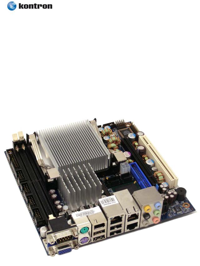
986LCD-M Family
KTD-N0837-B |
Public |
User Manual |
Date: 2012-04-17 Page |
23 of 91 |
4.1.2986LCD-M/mITX BGA
Same connectors available as on the standard 986LCD-M/mITX, except that CPU socket is replaced with BGA version of CPU. (Passive cooler included).
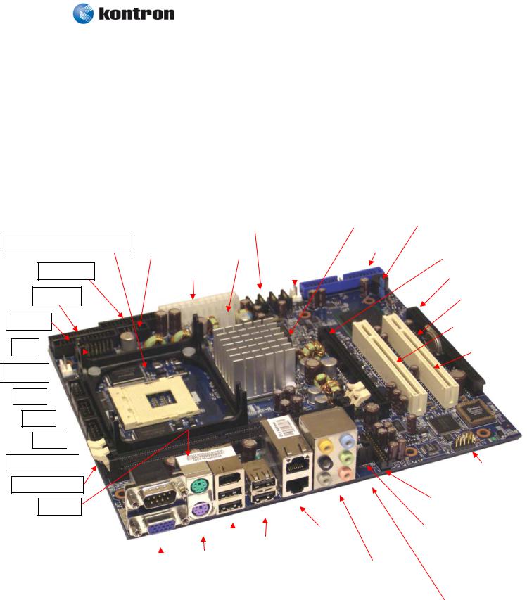
986LCD-M Family
KTD-N0837-B |
Public |
User Manual |
Date: 2012-04-17 Page |
24 of 91 |
4.1.3986LCD-M/Flex
System Temperature sensor (Q12)
FRONTPNL
FEATURE
PRINTER
TPM FAN_CPU

COM2 
 COM4
COM4 

COM3  DDR2 SLOT 0
DDR2 SLOT 1
KBDMSE
|
|
|
|
SATA1 SATA2 SATA0 SATA3 |
|
LVDS |
|
|
Clr-CMOS |
|
|
|
|
|
||||||||||
|
|
|
|
|
|
|
|
|
|
|
|
|
|
|
|
|
|
|
|
|
|
|
|
|
|
|
|
|
|
|
|
|
|
|
|
|
IDE_P |
|
|
|
|
|
|
|
|
|
|
||
USB6_7 |
|
|
ATX+12V |
|
FAN_System |
|
|
|
|
PCIe x16 / SDVO |
|
|||||||||||||
|
|
|
|
|
|
|
|
|
|
|
||||||||||||||
|
|
|
|
|||||||||||||||||||||
|
|
|
|
|
|
|
|
|
|
|
|
|
|
|
|
|
|
|
|
|
|
|
|
|
|
|
|
|
|
|
|
|
|
|
|
|
|
|
|
|
|
|
|
|
|
|
|
|
|
|
ATX/ BTXPWR |
|
|
|
|
|
|
|
|
|
|
|
|
|
|
|
|
|||||||
|
|
|
|
|
|
|
|
|
|
|
|
|
|
PCIe x4 |
|
|
|
|||||||
|
|
|
|
|
|
|
|
|
|
|
|
|
|
|
|
|
|
|
|
|
|
|||
|
|
|
|
|
|
|
|
|
|
|
|
|
|
|
|
|
|
|
|
|
||||
|
|
|
|
|
|
|
|
|
|
|
|
|
|
|
|
|
|
|
|
SPI |
|
|
|
|
|
|
|
|
|
|
|
|
|
|
|
|
|
|
|
|
|
|
|
|
|
|
|
|
|
|
|
|
|
|
|
|
|
|
|
|
|
|
|
|
|
|
|
|
PCI Slot 1 |
|
|
|||
|
|
|
|
|
|
|
|
|
|
|
|
|
|
|
|
|
|
|
|
|
|
|
|
|
|
|
|
|
|
|
|
|
|
|
|
|
|
|
|
|
|
|
|
|
|
|
|
||
|
|
|
|
|
|
|
|
|
|
|
|
|
|
|
|
|
|
|
|
|
PCI Slot 2 |
|||
|
|
|
|
|
|
|
|
|
|
|
|
|
|
|
|
|
|
|
|
|
|
|
|
|
|
|
|
|
|
|
|
|
|
|
|
|
|
|
|
|
|
|
|
|
IEEE1394_1 |
|||
|
|
|
|
|
|
|
|
|
|
|
|
|
|
|
|
|
|
|
|
(Not mounted) |
|||
|
|
|
|
|
|
|
|
|
|
|
|
|
|
|
|
|
|
|
|
|
|
|
|
|
|
|
|
|
|
|
|
|
|
|
|
|
|
|
|
|
|
|
|
|
|
||
|
|
|
|
|
|
|
|
|
|
|
|
|
|
|
|
|
|
|
AUDIO_HEAD |
|
|||
|
|
|
|
|
|
|
|
|
|
|
|
|
|
|
|
|
|
|
|
|
|
|
|
|
|
|
|
|
|
|
|
|
|
|
|
|
|
|
|
|
|
|
|
|
|
|
|
|
|
|
|
|
|
|
|
|
|
|
|
ETHER2 |
|
|
|
|
|
CDROM |
|
|
|
||
|
|
|
|
|
|
|
|
USB2 |
|
ETHER3 |
|
|
|
|
|
Audio in |
|
|
|
||||
|
|
|
MSE |
|
|
|
USB0 |
|
|
|
|
|
|
|
|
|
|
|
|
|
|||
|
|
|
|
|
|
|
|
|
|
|
|
|
|
|
|
|
|
|
|||||
COM1 |
|
KBD |
|
|
|
|
|
|
|
|
|
AUDIO STACK |
|
|
|
|
|
|
|
||||
|
|
|
|
|
|
|
|
|
|
|
|
|
|
|
|
|
|
|
|
|
|
||
CRT |
|
|
|
|
|
|
|
|
|
|
|
|
|
|
|
|
|
|
|
|
|
|
|
|
|
|
|
|
|
|
|
|
|
|
|
|
|
|
|
|
|
|
|
|
|
|
|
|
|
|
|
IEEE1394_0 |
|
|
|
|
|
|
|
|
|
|
|
|
|
|
|
||||
|
|
|
|
|
|
|
|
|
|
|
|
TV-OUT |
|
|
|||||||||
|
|
|
|
|
USB5 |
|
|
|
|
|
|
|
|
|
|||||||||
|
|
|
|
|
|
|
ETHER1 is not available |
|
|||||||||||||||
|
|
|
|
|
USB4 |
|
|
|
(Not available) |
|
|
||||||||||||
|
|
|
|
|
|
|
|
on this board |
|
|
|||||||||||||
|
|
|
|
|
|
|
|
|
|
|
|
|
|
|
|
|
|
|
|
||||
|
|
|
|
|
|
|
|
|
|
|
|
|
|
|
|
|
|
|
|
|
|
|
|
|
|
|
|
|
|
|
|
|
|
|
|
|
|
|
|
|
|
|
|
|
|
|
|
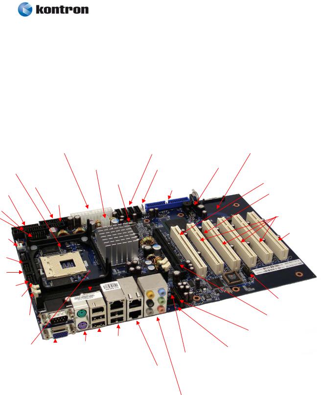
986LCD-M Family
KTD-N0837-B |
Public |
User Manual |
Date: 2012-04-17 Page |
25 of 91 |
4.1.4986LCD-M/ATXP
|
|
|
|
|
|
|
|
|
|
|
|
|
|
|
|
|
|
|
|
|
|
|
|
|
|
|
|
|
|
|
|
|
|
|
|
|
|
|
|
|
|
|
|
|
|
|
|
|
|
Mini-PCIe (*) |
|
|
|
|
|
|
||||||||
|
|
|
|
|
|
|
|
|
|
|
|
|
|
|
|
|
ATX/ BTXPWR |
|
|
|
|
|
|
SATA1 SATA2 SATA0 SATA3 |
|
|
|
|
|
|||||||||||||||||||||||||||||||||||
|
|
|
|
|
|
|
|
|
|
|
|
|
|
|
|
|
|
|
|
|
|
|
|
|
|
|
|
|
|
|
|
|
|
|
|
|
|
|
|
|
|
|
|
|
|
|
|
|
|
|
|
|
|
|
|
|
|
|
|
|
|
|
|
|
|
|
|
|
|
|
|
|
|
|
|
|
|
|
|
|
|
|
|
|
|
|
|
|
|
ATX+12V |
|
|
|
|
|
|
|
|
FAN_System |
|
|
Clr-CMOS |
|
|
|
|
|
|
|
|
|
|
|||||||||||||||||
System Temperature sensor (Q12) |
|
|
|
|
|
|
|
|
|
|||||||||||||||||||||||||||||||||||||||||||||||||||||||
|
|
|
|
|
|
|
|
|
|
|
|
|
|
|
|
|
|
|
|
|
|
|
|
|
|
|
|
|
|
|
|
|
|
|
|
|
|
|
|
|
|
|
|
|
||||||||||||||||||||
|
|
|
|
|
|
|
|
|
|
|
|
|
|
|
|
|
|
|
|
|
|
|
|
|
|
|
|
|
|
|
|
|
|
|
|
|
|
|
|
|
|
|
|
|
|
|
|
|
|
|
|
|
PCI Slot 1 |
|
|
|
|
|
||||||
|
|
|
|
|
|
|
|
|
|
|
|
|
|
|
FRONTPNL |
|
|
|
|
|
|
|
|
LVDS |
|
|
|
|
|
IDE_P |
|
|
|
|
|
|
|
|
|
|
|
|
|
|
||||||||||||||||||||
|
|
|
|
|
|
|
|
|
|
|
|
|
|
|
|
|
|
|
|
|
|
|
|
|
|
|
|
|
|
|
|
|
|
|
|
|
|
|
|
|
|
|
|
|
|
|
|
|
||||||||||||||||
|
|
|
FEATURE |
|
|
|
|
|
|
|
|
|
|
|
|
|
|
|
|
|
|
|
|
|
|
|
|
|
|
|
|
|
|
|
|
|
|
|
|
|
|
|
|
|
|
|
||||||||||||||||||
|
|
|
|
|
|
|
|
|
|
|
|
|
|
|
|
|
|
|
|
|
|
|
|
|
|
|
|
|
|
|
|
|
|
|
|
|
|
|
|
|
|
|
|
|
|
|||||||||||||||||||
|
|
|
|
|
|
|
|
|
|
|
|
|
|
|
|
|
|
|
|
|
|
|
|
|
|
|
|
|
|
|
|
|
|
|
|
|
|
|
|
|
|
|
|
|
|
|
|
|
|
|
|
|
|
|
|
|
||||||||
|
|
|
|
|
|
|
|
|
|
|
|
|
|
|
|
|
|
USB6_7 |
|
|
|
|
|
|
|
|
|
|
|
|
|
|
|
|
|
|
|
|
|
|
|
|
|
|
|
|
|
|
|
SPI |
|
|||||||||||||
|
|
|
|
|
|
|
|
|
|
|
|
|
|
|
|
|
|
|
|
|
|
|
|
|
|
|
|
|
|
|
|
|
|
|
|
|
|
|
||||||||||||||||||||||||||
|
PRINTER |
|
|
|
|
|
|
|
|
|
|
|
|
|
|
|
|
|
|
|
|
|
|
|
|
|
|
|
|
|
|
|
|
|
|
|
|
|
|
|
|
|
|
|
|
|
|
|
|
|
|
|
|
|
|
|||||||||
|
|
|
|
|
|
|
|
|
|
|
|
|
|
|
|
|
|
|
|
|
|
|
|
|
|
|
|
|
|
|
|
|
|
|
|
|
|
|
|
|
|
|
|
|
|
|
|
|
|
|
||||||||||||||
|
|
|
|
|
|
|
|
|
|
|
|
|
|
|
|
|
|
|
|
|
|
|
|
|
|
|
|
|
|
|
|
|
|
|
|
|
|
|
|
|
|
|
|
|
|
|
|
|
|
|
|
|
|
|
|
|
|
PCI Slot 2 - 5 |
|
|||||
|
|
|
|
TPM |
|
|
|
|
|
|
|
|
|
|
|
|
|
|
|
|
|
|
|
|
|
|
|
|
|
|
|
|
|
|
|
|
|
|
|
|
|
|
|
|
|
|
|
|
|
|
|
|
|
|
|
|||||||||
|
|
|
|
|
|
|
|
|
|
|
|
|
|
|
|
|
|
|
|
|
|
|
|
|
|
|
|
|
|
|
|
|
|
|
|
|
|
|
|
|
|
|
|
|
|
|
|
|
|
|
|
|
|
|
|
|
|
|
|
|||||
|
|
|
|
|
|
|
|
|
|
|
|
|
|
|
|
|
|
|
|
|
|
|
|
|
|
|
|
|
|
|
|
|
|
|
|
|
|
|
|
|
|
|
|
|
|
|
|
|
|
|
|
|
|
|
|
|
|
|
|
|
|
|
|
|
|
|
|
|
|
|
|
|
|
|
|
|
|
|
|
|
|
|
|
|
|
|
|
|
|
|
|
|
|
|
|
|
|
|
|
|
|
|
|
|
|
|
|
|
|
|
|
|
|
|
|
|
|
|
|
|
|
|
|
|
|
|
|
|
|
|
FAN_CPU |
|
|
|
|
|
|
|
|
|
|
|
|
|
|
|
|
|
|
|
|
|
|
|
|
|
|
|
|
|
|
|
|
|
|
|
|
|
|
|
|
|
|
|
|
|
|
|
|
|
|
|
|
PCI Slot 6 |
||||||||||
|
|
|
|
|
|
|
|
|
|
|
|
|
|
|
|
|
|
|
|
|
|
|
|
|
|
|
|
|
|
|
|
|
|
|
|
|
|
|
|
|
|
|
|
|
|
|
|
|
|
|
|
|
|
|
|
|
|
|
|
|
|
|
|
|
|
|
|
|
|
|
|
|
|
|
|
|
|
|
|
|
|
|
|
|
|
|
|
|
|
|
|
|
|
|
|
|
|
|
|
|
|
|
|
|
|
|
|
|
|
|
|
|
|
|
|
|
|
|
|
|
|
|
|
|
|
|
|||
|
|
|
|
COM2 |
|
|
|
|
|
|
|
|
|
|
|
|
|
|
|
|
|
|
|
|
|
|
|
|
|
|
|
|
|
|
|
|
|
|
|
|
|
|
|
|
|
|
|
|
|
|
|
|
|
|
|
|
|
|
|
|||||
|
|
|
|
|
|
|
|
|
|
|
|
|
|
|
|
|
|
|
|
|
|
|
|
|
|
|
|
|
|
|
|
|
|
|
|
|
|
|
|
|
|
|
|
|
|
|
|
|
|
|
|
|
|
|
|
|
|
|
|
|||||
|
|
|
|
|
COM4 |
|
|
|
|
|
|
|
|
|
|
|
|
|
|
|
|
|
|
|
|
|
|
|
|
|
|
|
|
|
|
|
|
|
|
|
|
|
|
|
|
|
|
|
|
|
|
|
|
|
|
|
|
|
||||||
|
|
|
|
|
|
|
|
|
|
|
|
|
|
|
|
|
|
|
|
|
|
|
|
|
|
|
|
|
|
|
|
|
|
|
|
|
|
|
|
|
|
|
|
|
|
|
|
|
|
|
|
|
||||||||||||
|
|
|
|
|
|
|
|
|
|
|
|
|
|
|
|
|
|
|
|
|
|
|
|
|
|
|
|
|
|
|
|
|
|
|
|
|
|
|
|
|
|
|
|
|
|
|
|
|
|
|
|
|
|
|
|
|
|
|
||||||
|
|
|
|
|
|
COM3 |
|
|
|
|
|
|
|
|
|
|
|
|
|
|
|
|
|
|
|
|
|
|
|
|
|
|
|
|
|
|
|
|
|
|
|
|
|
|
|
|
|
|
|
|
|
|
|
|
|
|
|
|
||||||
|
|
|
|
|
|
|
|
|
|
|
|
|
|
|
|
|
|
|
|
|
|
|
|
|
|
|
|
|
|
|
|
|
|
|
|
|
|
|
|
|
|
|
|
|
|
|
|
|
|
|
|
|
||||||||||||
|
|
|
|
|
|
|
|
|
|
|
|
|
|
|
|
|
|
|
|
|
|
|
|
|
|
|
|
|
|
|
|
|
|
|
|
|
|
|
|
|
|
|
|
|
|
|
|
|
|
|
|
|
|
|
|
|
|
|
IEEE1394 1 |
|||||
|
|
|
DDR2 SLOT 0 |
|
|
|
|
|
|
|
|
|
|
|
|
|
|
|
|
|
|
|
|
|
|
|
|
|
|
|
|
|
|
|
|
|
|
|
|
|
|
|
|
|
||||||||||||||||||||
|
|
|
|
|
|
|
|
|
|
|
|
|
|
|
|
|
|
|
|
|
|
|
|
|
|
|
|
|
|
|
|
|
|
|
|
|
|
|
|
|
|
|
|
|
|
|
|
|
|
|
|
|
|
|
||||||||||
|
|
|
|
|
|
|
|
|
|
|
|
|
|
|
|
|
|
|
|
|
|
|
|
|
|
|
|
|
|
|
|
|
|
|
|
|
|
|
|
|
|
|
|
|
|
|
|
|
|
|
|
|
|
|
|
|
|
|
|
|
|
|
|
|
|
|
|
|
DDR2 SLOT 1 |
|
|
|
|
|
|
|
|
|
|
|
|
|
|
|
|
|
|
|
|
|
|
|
|
|
|
|
|
|
|
|
|
|
|
|
|
|
|
|
|
|
PCIe x16 / SDVO |
||||||||||||||||||
|
|
|
|
|
|
|
|
|
|
|
|
|
|
|
|
|
|
|
|
|
|
|
|
|
|
|
|
|
|
|
|
|
|
|
|
|
|
|
|
|
|
|
|
|
|
|
|
|
|
|
|
|
|
|
|
|
|
|
|
|
||||
|
|
|
|
|
|
|
|
|
|
|
|
|
|
|
|
|
|
|
|
|
|
|
|
|
|
|
|
|
|
|
|
|
|
|
|
|
|
|
|
|
|
|
|
|
|
|
|
|
|
|
|
AUDIO HEADER |
|
|
||||||||||
|
|
|
|
|
|
|
|
|
|
|
|
|
|
|
|
|
|
|
|
|
|
|
|
|
|
|
|
|
|
ETHER1 |
|
|
|
|
|
|
|
|
|
|
|
|
|
|
|
|
|
|||||||||||||||||
|
|
|
|
|
|
|
KBDMSE |
|
|
|
|
|
|
|
|
|
MSE |
|
|
|
|
|
|
|
|
|
|
|
|
|
|
|
|
|
|
|
|
|
|
|
|
|
|
|
|
|
|
|
|
|||||||||||||||
|
|
|
|
|
|
|
|
|
|
|
|
|
|
|
|
|
|
|
|
|
|
USB2 |
|
|
|
|
|
|
|
|
|
|
|
|
|
|
|
|
|
|
|
|
|
|
|
|
|
|
|
|
||||||||||||||
|
|
|
|
|
|
|
|
|
|
|
|
|
|
|
|
|
|
|
|
|
|
|
|
|
|
|
|
|
|
|
|
|
|
TV-OUT |
|
|
|
|
|
|
|
|
|
|||||||||||||||||||||
|
|
|
|
|
|
|
|
|
|
|
|
|
|
|
|
|
COM1 |
|
|
|
KBD |
|
|
|
|
|
|
USB0 |
|
|
|
|
|
|
CDROM |
|
|
|
|
|
|
|
||||||||||||||||||||||
|
|
|
|
|
|
|
|
|
|
|
|
|
|
|
|
|
|
|
|
|
|
|
|
|
|
|
|
|
|
|
|
|
|
(Not available) |
|
|
|
|
|
|
||||||||||||||||||||||||
|
|
|
|
|
|
|
|
|
|
|
|
|
|
|
|
|
CRT |
|
|
|
|
|
|
|
|
|
|
|
|
|
|
|
|
|
|
|
|
|
|
Audio in |
|
|
|
|
|
|
|
|
|
|
|
|
|
|
|
|
|
|||||||
|
|
|
|
|
|
|
|
|
|
|
|
|
|
|
|
|
|
|
|
|
|
|
|
|
|
|
|
|
|
|
|
|
|
|
|
|
|
|
|
|
|
|
|
|
|
|
|
|
|
|
|
|
|
|
|
|||||||||
|
|
|
|
|
|
|
|
|
|
|
|
|
|
|
|
|
|
|
|
|
|
|
|
|
|
|
|
|
|
|
|
|
ETHER2 |
|
|
|
|
|
|
|
|
|
|
|
|
|
|
|
|
|
|
|||||||||||||
|
|
|
|
|
|
|
|
|
|
|
|
|
|
|
|
|
|
|
|
|
|
|
|
|
IEEE1394_0 |
|
|
|
|
|
|
|
|
|
|
|
|
|
|
|
|
|
|
|
|
|
|
|
|
|
|
|||||||||||||
|
|
|
|
|
|
|
|
|
|
|
|
|
|
|
|
|
|
|
|
|
|
|
|
|
|
|
ETHER3 |
|
|
|
|
|
|
|
|
|
|
|
|
|
|
|
|
|
|
|
|
|
|
|
||||||||||||||
|
|
|
|
|
|
|
|
|
|
|
|
|
|
|
|
|
|
|
|
|
|
|
|
|
|
USB5 |
|
|
|
|
|
|
|
|
|
|
|
|
|
|
|
|
|
|
|
|
|
|
|
|
|
|
||||||||||||
|
|
|
|
|
|
|
|
|
|
|
|
|
|
|
|
|
|
|
|
|
|
|
|
|
|
|
|
|
|
|
|
|
|
|
|
|
|
|
|
|
|
|
|
|
|
|
|
|
|
|
|
|
|
|
|
|
|
|
||||||
|
|
|
|
|
|
|
|
|
|
|
|
|
|
|
|
|
|
|
|
|
|
|
|
|
|
USB4 |
|
|
|
|
|
|
|
|
|
|
|
|
|
|
|
|
|
|
|
|
|
|
|
|
|
|
|
|
|
|
|
|
|
|||||
|
|
|
|
|
|
|
|
|
|
|
|
|
|
|
|
|
|
|
|
|
|
|
|
|
|
|
|
|
|
|
|
|
|
|
|
|
|
|
|
|
|
|
|
|
|
|
|
|
|
|
|
|
|
|
|
|
|
|
||||||
|
|
|
|
|
|
|
|
|
|
|
|
|
|
|
|
|
|
|
|
|
|
|
|
|
|
|
|
|
|
|
|
|
|
|
|
|
|
|
|
AUDIO STACK |
|
|
|
|
|
|
|
|
|
|
|
|
|
|
|
|
|
|
||||||
|
|
|
|
|
|
|
|
|
|
|
|
|
|
|
|
|
|
|
|
|
|
|
|
|
|
|
|
|
|
|
|
|
|
|
|
|
|
|
|
|
|
|
|
|
|
|
|
|
|
|
|
|
|
|
||||||||||
|
|
|
|
|
|
|
|
|
|
|
|
|
|
|
|
|
|
|
|
|
|
|
|
|
|
|
|
|
|
|
|
|
|
|
|
|
|
|
|
|
|
|
|
|
|
|
|
|
|
|
|
|
|
|
|
|
|
|
|
|
|
|
|
|
* Support for Mini PCI-Express modules with no components mounted on backside.
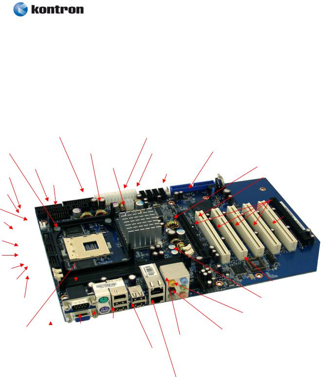
986LCD-M Family
KTD-N0837-B |
Public |
User Manual |
Date: 2012-04-17 Page |
26 of 91 |
4.1.5986LCD-M/ATXE
|
|
|
|
|
|
|
|
|
|
|
|
|
|
|
|
|
|
|
ATX/ BTXPWR |
|
|
|
|
|
|
SATA1 SATA2 SATA0 SATA3 |
|
|
|
|
|
|
|
|
|
|
|
|
|
|
|
|
|
|
|
|
|||||||||||||||||||||
|
|
|
|
|
|
|
|
|
|
|
|
|
|
|
|
|
|
|
|
|
|
|
|
|
|
|
|
|
|
|
|
|
|
|
|
|
|
|
|
|
|
|
|
|
|
|
|
|
|
|
|
|
|
|
|
|
|
|
|
|
|
|
|
|
|
|
|
|
System Temperature sensor (Q12) |
|
|
|
|
|
ATX+12V |
|
|
|
|
|
|
FAN_System |
|
|
Clr-CMOS |
|
|
|
|
|
|
|
|
|
|
||||||||||||||||||||||||||||||||||||||||
|
|
|
|
|
|
|
|
|
|
|
|
|
|
|
|
|
|
|
|
|
|
|
|
|
|
|
|
|
|
|
|
|
|
|
|
|
|
|
|
|
|
|
|
|
|
|
|
|
|
|
|
|
|
|
|
|
|
|
|
|
|
|
|
|
|
|
|
|
|
|
|
|
|
|
|
|
|
|
|
|
|
|
|
|
|
|
|
|
|
|
|
|
|
|
|
|
|
|
|
|
|
|
|
|
|
|
|
|
|
|
|
|
|
|
|
|
|
|
|
|
|
|
PCI Slot 1 |
|
|
|
|
|
|
|
|||||
|
|
|
|
|
|
|
|
|
|
|
|
|
|
|
|
|
FRONTPNL |
|
|
|
|
|
|
|
|
|
|
LVDS |
|
|
|
|
|
|
|
|
|
|
|
|
|
|
|
|
|
|
|
|
|
|
|
||||||||||||||||
|
|
|
|
|
|
|
|
|
|
|
|
|
|
|
|
|
|
|
|
|
|
|
|
|
|
|
|
|
|
|
|
IDE_P |
|
|
|
|
|||||||||||||||||||||||||||||||
|
|
|
|
FEATURE |
|
|
|
|
|
|
|
|
|
|
|
|
|
|
|
|
|
|
|
|
|
|
|
|
|
|
|
|
|
|
|
|
|
|
|
|
|
|
|
|
|
|
|
|
|
|
|
|
|
|
|
|
|||||||||||
|
|
|
|
|
|
|
|
|
|
|
|
|
|
|
|
|
|
|
|
USB6_7 |
|
|
|
|
|
|
|
|
|
|
|
|
|
|
|
|
|
|
|
|
|
|
|
|
|
|
|
|
SPI |
|
|
||||||||||||||||
|
|
|
|
|
|
|
|
|
|
|
|
|
|
|
|
|
|
|
|
|
|
|
|
|
|
|
|
|
|
||||||||||||||||||||||||||||||||||||||
|
|
|
|
PRINTER |
|
|
|
|
|
|
|
|
|
|
|
|
|
|
|
|
|
|
|
|
|
|
|
|
|
|
|
|
|
|
|
|
|
|
|
|
|
|
|
|
|
|
|
|
|
|
|
|
|
|
|||||||||||||
|
|
|
|
|
|
|
|
|
|
|
|
|
|
|
|
|
|
|
|
|
|
|
|
|
|
|
|
|
|
|
|
|
|
|
|
|
|
|
|
|
|
|
|
|
|
|
|
|
|
|
|
|
|
|
|
|
|
|
|
PCI Slot 2 - 5 |
|
||||||
|
|
|
|
|
|
TPM |
|
|
|
|
|
|
|
|
|
|
|
|
|
|
|
|
|
|
|
|
|
|
|
|
|
|
|
|
|
|
|
|
|
|
|
|
|
|
|
|
|
|
|
|
|
|
|
|
|
|
|||||||||||
|
|
|
|
|
|
|
|
|
|
|
|
|
|
|
|
|
|
|
|
|
|
|
|
|
|
|
|
|
|
|
|
|
|
|
|
|
|
|
|
|
|
|
|
|
|
|
|
|
|
|
|
|
|
|
|
|
|
|
|||||||||
|
|
|
|
|
|
|
|
|
|
|
|
|
|
|
|
|
|
|
|
|
|
|
|
|
|
|
|
|
|
|
|
|
|
|
|
|
|
|
|
|
|
|
|
|
|
|
|
|
|
|
|
|
|
|
|
|
|
|
|
|
|
|
|
|
|
|
|
|
|
|
|
|
|
|
|
|
|
|
|
|
|
|
|
|
|
|
|
|
|
|
|
|
|
|
|
|
|
|
|
|
|
|
|
|
|
|
|
|
|
|
|
|
|
|
|
|
|
|
|
|
|
|
|
|
|
|
|
|
|
|
|
|
|
|
|
|
FAN_CPU |
|
|
|
|
|
|
|
|
|
|
|
|
|
|
|
|
|
|
|
|
|
|
|
|
|
|
|
|
|
|
|
|
|
|
|
|
|
|
|
|
|
|
|
|
|
|
|
|
|
PCIe x4 |
||||||||||||||||
|
|
|
|
|
|
|
|
|
|
|
|
|
|
|
|
|
|
|
|
|
|
|
|
|
|
|
|
|
|
|
|
|
|
|
|
|
|
|
|
|
|
|
|
|
|
|
|
|
|
|
|
|
|
|
|
|
|
|
|
|
|
|
(in x16 socket) |
||||
|
|
|
|
|
|
|
|
|
|
|
|
|
|
|
|
|
|
|
|
|
|
|
|
|
|
|
|
|
|
|
|
|
|
|
|
|
|
|
|
|
|
|
|
|
|
|
|
|
|
|
|
|
|
|
|
|
|
|
|
|
|||||||
|
|
|
|
|
|
|
|
|
|
|
|
|
|
|
|
|
|
|
|
|
|
|
|
|
|
|
|
|
|
|
|
|
|
|
|
|
|
|
|
|
|
|
|
|
|
|
|
|
|
|
|
|
|
|
|
|
|
|
|
||||||||
|
|
|
|
|
|
|
|
|
|
|
|
|
|
|
|
|
|
|
|
|
|
|
|
|
|
|
|
|
|
|
|
|
|
|
|
|
|
|
|
|
|
|
|
|
|
|
|
|
|
|
|
|
|
|
|
|
|
|
|
|
|
|
|
|
|
|
|
|
|
|
|
COM2 |
|
|
|
|
|
|
|
|
|
|
|
|
|
|
|
|
|
|
|
|
|
|
|
|
|
|
|
|
|
|
|
|
|
|
|
|
|
|
|
|
|
|
|
|
|
|
|
|
|
|
|
|
|
||||||||||
|
|
|
|
|
|
|
|
|
|
|
|
|
|
|
|
|
|
|
|
|
|
|
|
|
|
|
|
|
|
|
|
|
|
|
|
|
|
|
|
|
|
|
|
|
|
|
|
|
|
|
|
|
|
|
|||||||||||||
|
|
|
|
|
|
COM4 |
|
|
|
|
|
|
|
|
|
|
|
|
|
|
|
|
|
|
|
|
|
|
|
|
|
|
|
|
|
|
|
|
|
|
|
|
|
|
|
|
|
|
|
|
|
|
|
|
|
|
|
|
|
|
|
|
|
||||
|
|
|
|
|
|
|
|
|
|
|
|
|
|
|
|
|
|
|
|
|
|
|
|
|
|
|
|
|
|
|
|
|
|
|
|
|
|
|
|
|
|
|
|
|
|
|
|
|
|
|
|
|
|
|
|
|
|
|
|
|
|
|
|
|
|
|
|
|
|
|
|
|
|
|
COM3 |
|
|
|
|
|
|
|
|
|
|
|
|
|
|
|
|
|
|
|
|
|
|
|
|
|
|
|
|
|
|
|
|
|
|
|
|
|
|
|
|
|
|
|
|
|
|
|
|
|
|
|
|
|
|
||||||
|
|
|
|
|
|
|
|
|
|
|
|
|
|
|
|
|
|
|
|
|
|
|
|
|
|
|
|
|
|
|
|
|
|
|
|
|
|
|
|
|
|
|
|
|
|
|
|
|
|
|
|
|
|
|
|
|
|
|
|
IEEE1394 1 |
|
||||||
|
|
|
|
|
|
|
|
|
|
|
|
|
|
|
|
|
|
|
|
|
|
|
|
|
|
|
|
|
|
|
|
|
|
|
|
|
|
|
|
|
|
|
|
|
|
|
|
|
|
|
|
|
|
|
|
|
|
|
|
|
|||||||
|
|
|
DDR2 SLOT 0 |
|
|
|
|
|
|
|
|
|
|
|
|
|
|
|
|
|
|
|
|
|
|
|
|
|
|
|
|
|
|
|
|
|
|
|
|
|
|
|
|
|
|||||||||||||||||||||||
|
|
|
|
|
|
|
|
|
|
|
|
|
|
|
|
|
|
|
|
|
|
|
|
|
|
|
|
|
|
|
|
|
|
|
|
|
|
|
|
|
|
|
|
|
|
|
|
|
|
|
|
|
|
|
|
||||||||||||
|
|
|
|
|
|
|
|
|
|
|
|
|
|
|
|
|
|
|
|
|
|
|
|
|
|
|
|
|
|
|
|
|
|
|
|
|
|
|
|
|
|
|
|
|
|
|
|
|
|
|
|
|
|
|
|
|
|
|
|
|
|
|
|
|
|
|
|
|
|
|
DDR2 SLOT 1 |
|
|
|
|
|
|
|
|
|
|
|
|
|
|
|
|
|
|
|
|
|
|
|
|
|
|
|
|
|
|
|
|
|
|
|
|
|
|
|
|
|
PCIe x16 / SDVO |
|
|||||||||||||||||||||
|
|
|
|
|
|
|
|
|
|
|
|
|
|
|
|
|
|
|
|
|
|
|
|
|
|
|
|
|
|
|
|
|
|
|
|
|
|
|
|
|
|
|
|
|
|
|
|
|
|
|
|
|
|
|
|
|
|
|
|
|
|
|
|||||
|
|
|
|
|
|
|
|
|
|
|
|
|
|
|
|
|
|
|
|
|
|
|
|
|
|
|
|
|
|
|
|
|
|
|
|
|
|
|
|
|
|
|
|
|
|
|
|
|
|
|
|
|
|
AUDIO HEADER |
|
|
|
||||||||||
|
|
|
|
|
|
|
|
|
|
|
|
|
|
|
|
|
|
|
|
|
|
|
|
|
|
|
|
|
|
|
|
|
ETHER1 |
|
|
|
|
|
|
|
|
|
|
|
|
|
|
|
|
|
|
||||||||||||||||
|
|
|
|
|
|
|
|
KBDMSE |
|
|
|
|
|
|
|
|
MSE |
|
|
|
|
|
|
|
|
|
|
|
|
|
|
|
|
|
|
|
|
|
|
|
|
|
|
|
|
|
|
|
|
|
|||||||||||||||||
|
|
|
|
|
|
|
|
|
|
|
|
|
|
|
|
|
|
|
USB2 |
|
|
|
|
|
|
|
|
|
|
|
|
|
|
|
|
|
|
|
|
|
|
|
|
|
|
|
|
|
|||||||||||||||||||
|
|
|
|
|
|
|
|
|
|
|
|
|
|
|
|
|
|
|
|
|
|
|
|
|
|
|
|
|
|
|
|
TV-OUT |
|
|
|
|
|
|
|
|
|
|
|||||||||||||||||||||||||
|
|
|
|
|
|
|
|
|
|
|
|
|
|
|
|
|
|
|
COM1 |
|
|
KBD |
|
|
|
|
USB0 |
|
|
|
|
|
|
CDROM |
|
|
|
|
|
|
|
|
|||||||||||||||||||||||||
|
|
|
|
|
|
|
|
|
|
|
|
|
|
|
|
|
|
|
|
|
|
|
|
|
|
|
|
|
|
|
|
|
|
|
|
|
|
(Not available) |
|
|
|
|
|
|
|||||||||||||||||||||||
|
|
|
|
|
|
|
|
|
|
|
|
|
|
|
|
|
|
|
CRT |
|
|
|
|
|
|
|
|
|
|
|
|
|
|
|
|
|
|
|
|
|
|
Audio in |
|
|
|
|
|
|
|
|
|
|
|
|
|
|
|
|
|
|
|||||||
|
|
|
|
|
|
|
|
|
|
|
|
|
|
|
|
|
|
|
|
|
|
|
|
|
|
|
|
|
|
|
|
|
|
|
|
|
|
|
|
|
|
|
|
|
|
|
|
|
|
|
|
|
|
|
|
|
|
|
|||||||||
|
|
|
|
|
|
|
|
|
|
|
|
|
|
|
|
|
|
|
|
|
|
|
|
|
|
|
|
|
|
|
|
|
|
|
ETHER2 |
|
|
|
|
|
|
|
|
|
|
|
|
|
|
|
|
|
|
|
|||||||||||||
|
|
|
|
|
|
|
|
|
|
|
|
|
|
|
|
|
|
|
|
|
|
|
|
|
|
|
IEEE1394_0 |
|
|
|
|
|
|
|
|
|
|
|
|
|
|
|
|
|
|
|
|
|
|
|
|
|
|
|
|||||||||||||
|
|
|
|
|
|
|
|
|
|
|
|
|
|
|
|
|
|
|
|
|
|
|
|
|
|
|
|
|
ETHER3 |
|
|
|
|
|
|
|
|
|
|
|
|
|
|
|
|
|
|
|
|
|
|
|
|
||||||||||||||
|
|
|
|
|
|
|
|
|
|
|
|
|
|
|
|
|
|
|
|
|
|
|
|
|
|
|
|
USB5 |
|
|
|
|
|
|
|
|
|
|
|
|
|
|
|
|
|
|
|
|
|
|
|
|
|
|
|
|
|||||||||||
|
|
|
|
|
|
|
|
|
|
|
|
|
|
|
|
|
|
|
|
|
|
|
|
|
|
|
|
|
|
|
|
|
|
|
|
|
|
|
|
|
|
|
|
|
|
|
ETHER1 is not available |
|
|
|
|
||||||||||||||||
|
|
|
|
|
|
|
|
|
|
|
|
|
|
|
|
|
|
|
|
|
|
|
|
|
|
|
|
USB4 |
|
|
|
|
|
|
|
|
|
|
|
|
|
|
|
|
|
|
|
|
|||||||||||||||||||
|
|
|
|
|
|
|
|
|
|
|
|
|
|
|
|
|
|
|
|
|
|
|
|
|
|
|
|
|
|
|
|
|
|
|
|
|
|
|
|
|
|
|
|
|
|||||||||||||||||||||||
|
|
|
|
|
|
|
|
|
|
|
|
|
|
|
|
|
|
|
|
|
|
|
|
|
|
|
|
|
|
|
|
|
|
|
|
|
|
|
|
|
|
AUDIO STACK |
|
|
|
|
|
on this board |
|
||||||||||||||||||
|
|
|
|
|
|
|
|
|
|
|
|
|
|
|
|
|
|
|
|
|
|
|
|
|
|
|
|
|
|
|
|
|
|
|
|
|
|
|
|
|
|
|
|
|
|
|
|||||||||||||||||||||
|
|
|
|
|
|
|
|
|
|
|
|
|
|
|
|
|
|
|
|
|
|
|
|
|
|
|
|
|
|
|
|
|
|
|
|
|
|
|
|
|
|
|
|
|
|
|
|
|
|
|
|
|
|
|
|
|
|
|
|
|
|||||||
|
|
|
|
|
|
|
|
|
|
|
|
|
|
|
|
|
|
|
|
|
|
|
|
|
|
|
|
|
|
|
|
|
|
|
|
|
|
|
|
|
|
|
|
|
|
|
|
|
|
|
|
|
|
|
|
|
|
|
|
|
|
|
|
|
|
|
|

986LCD-M Family
KTD-N0837-B |
Public |
User Manual |
Date: 2012-04-17 Page |
27 of 91 |
4.2Power Connector (ATXPWR)
The 986LCD-M boards are designed to be supplied from a standard ATX or BTX power supply.
ATX/ BTX Power Connector:
|
|
|
Pull |
|
|
|
|
|
|
PIN |
|
|
|
|
|
|
|
Pull |
|
|
|
|
Note |
|
U/D |
|
Ioh/Iol |
|
Type |
|
Signal |
|
|
|
Signal |
|
Type |
|
Ioh/Iol |
|
U/D |
|
Note |
|
|
|
- |
|
- |
|
PWR |
|
3V3 |
12 |
24 |
|
GND |
|
PWR |
|
- |
|
- |
|
|
|
|
|
|
|
|
|
|
|
|
11 |
23 |
|
|
|
|
|
|
|
|
|
|
|
|
|
|
|
|
|
PWR |
|
+12V |
|
5V |
|
PWR |
|
|
|
|
|
|
||
|
|
|
|
|
|
|
|
|
|
10 |
22 |
|
|
|
|
|
|
|
|
|
|
|
|
|
|
|
|
|
PWR |
|
+12V |
|
5V |
|
PWR |
|
|
|
|
|
|
||
|
|
|
|
|
|
|
|
|
|
9 |
21 |
|
|
|
|
|
|
|
|
|
|
|
|
|
- |
|
- |
|
PWR |
|
SB5V |
|
5V |
|
PWR |
|
- |
|
- |
|
|
||
|
|
|
|
|
|
|
|
|
|
8 |
20 |
|
|
|
|
|
|
|
|
|
|
|
|
|
- |
|
- |
|
I |
|
P_OK |
|
-5V |
|
PWR |
|
- |
|
- |
|
1 |
||
|
|
|
- |
|
- |
|
PWR |
|
GND |
7 |
19 |
|
GND |
|
PWR |
|
- |
|
- |
|
|
|
|
|
|
|
|
|
|
|
|
6 |
18 |
|
|
|
|
|
|
|
|
|
|
|
|
|
- |
|
- |
|
PWR |
|
5V |
|
GND |
|
PWR |
|
- |
|
- |
|
|
||
|
|
|
- |
|
- |
|
PWR |
|
GND |
5 |
17 |
|
GND |
|
PWR |
|
- |
|
- |
|
|
|
|
|
- |
|
- |
|
PWR |
|
5V |
4 |
16 |
|
PSON# |
|
OC |
|
- |
|
- |
|
|
|
|
|
|
|
|
|
|
|
|
3 |
15 |
|
|
|
|
|
|
|
|
|
|
|
|
|
- |
|
- |
|
PWR |
|
GND |
|
GND |
|
PWR |
|
- |
|
- |
|
|
||
|
|
|
|
|
|
|
|
|
|
2 |
14 |
|
|
|
|
|
|
|
|
|
|
|
|
|
- |
|
- |
|
PWR |
|
3V3 |
|
-12V |
|
PWR |
|
- |
|
- |
|
|
||
|
|
|
- |
|
- |
|
PWR |
|
3V3 |
1 |
13 |
|
3V3 |
|
PWR |
|
- |
|
- |
|
|
Note 1: -5V supply is not used onboard.
Note 2: Use of BTX supply not required for operation, but may be required to drive high-power PCI Express x16 Add cards.
ATX+12V Power Connector:
|
|
|
Pull |
|
|
|
|
|
|
|
|
PIN |
|
|
|
|
|
Pull |
|
|
|
|
Note |
|
U/D |
|
Ioh/Iol |
|
|
Type |
|
Signal |
|
|
|
Signal |
|
Type |
|
Ioh/Iol |
U/D |
|
Note |
|
1 |
|
- |
|
- |
|
|
PWR |
|
GND |
1 |
|
3 |
+12V |
|
PWR |
|
- |
- |
|
1 |
|
1 |
|
|
|
|
|
|
PWR |
|
GND |
2 |
|
4 |
+12V |
|
PWR |
|
|
|
|
1 |
Note 1: Use of the 4-pin ATX+12V Power Connector is required for operation of the 986LCD-M boards.
See chapter “Power Consumption” regarding input tolerances on 3.3V, 5V, SB5V, +12 and -12V (also refer to ATX specification).
Control signal description:
Signal |
Description |
P_OK |
P_OK is a power good signal and should be asserted high by the power supply to indicate that |
|
the +5VDC and +3.3VDC outputs are above the undervoltage thresholds of the power supply. |
|
When this signal is asserted high, there should be sufficient energy stored by the converter to |
|
guarantee continuous power operation within specification. Conversely, when the output |
|
voltages fall below the undervoltage threshold, or when mains power has been removed for a |
|
time sufficiently long so that power supply operation is no longer guaranteed, P_OK should be |
|
de-asserted to a low state. The recommended electrical and timing characteristics of the |
|
P_OK (PWR_OK) signal are provided in the ATX12V Power SupplyDesign Guide. |
|
It is strongly recommended to use an ATX or BTX supply with the 986LCD-M boards, in order |
|
to implement the supervision of the 5V and 3V3 supplies. These supplies are not supervised |
|
onboard the 986LCD-M boards. |
|
|
PS_ON# |
Active low open drain signal from the board to the power supply to turn on the power supply |
|
outputs. Signal must be pulled high by the power supply. |
|
|

986LCD-M Family
KTD-N0837-B |
Public |
User Manual |
Date: 2012-04-17 Page |
28 of 91 |
4.3Keyboard and PS/2 mouse connectors
Attachment of a keyboard or PS/2 mouse adapter can be done through the stacked PS/2 mouse and keyboard connector (MSE & KBD).
Both interfaces utilize open-drain signaling with on-board pull-up.
The PS/2 mouse and keyboard is supplied from 5V_STB when in standby mode in order to enable keyboard or mouse activity to bring the system out from power saving states. The supply is provided through a 1.1A resetable fuse.
4.3.1Stacked MINI-DIN keyboard and mouse Connector (MSE & KBD)
|
Pull |
|
|
|
|
PIN |
|
|
|
Pull |
|
|
Note |
U/D |
Ioh/Iol |
Type |
Signal |
|
|
|
Signal |
Type |
Ioh/Iol |
U/D |
Note |
|
- |
- |
- |
NC |
6 |
|
5 |
MSCLK |
IOC |
TBD |
4K7 |
|
|
- |
- |
PWR |
5V/SB5V |
4 |
|
3 |
GND |
PWR |
- |
- |
|
|
- |
- |
- |
NC |
|
2 |
1 |
MSDAT |
IOC |
TBD |
4K7 |
|
|
|
|
- |
NC |
6 |
|
5 |
KBDCLK |
IOC |
TBD |
4K7 |
|
|
- |
- |
PWR |
5V/SB5V |
4 |
|
3 |
GND |
PWR |
- |
- |
|
|
- |
- |
- |
NC |
|
2 |
1 |
KBDDAT |
IOC |
TBD |
4K7 |
|
Signal Description – Keyboard & and mouse Connector (MSE & KBD), see below.
4.3.2Keyboard and mouse pin-row Connector (KBDMSE)
PIN |
|
|
|
|
|
Pull |
|
|
|
|
|
|
|
|
|
||
Signal |
|
Type |
Ioh/Iol |
|
U/D |
|
Note |
|
|
|
|
|
|||||
1 |
KBDCLK |
|
IOC |
TBD |
|
4K7 |
|
|
2 |
KBDDAT |
|
IOC |
TBD |
|
4K7 |
|
|
3 |
|
|
|
|
|
|
|
|
MSCLK |
|
IOC |
TBD |
|
4K7 |
|
|
|
4 |
|
|
|
|
|
|
|
|
MSDAT |
|
IOC |
TBD |
|
4K7 |
|
|
|
5 |
5V/SB5V |
|
PWR |
- |
|
- |
|
|
6 |
GND |
|
PWR |
- |
|
- |
|
|
Signal Description – Keyboard & and mouse Connector (KBDMSE).
|
Signal |
|
|
Description |
|
|
|
|
|
||
|
MSCLK |
|
|
Bi-directional clock signal used to strobe data/commands from/to the PS/2 mouse. |
|
|
|
|
|
|
|
|
MSDAT |
|
|
Bi-directional serial data line used to transfer data from or commands to the PS/2 mouse. |
|
|
|
|
|
|
|
|
KDBCLK |
|
|
Bi-directional clock signal used to strobe data/commands from/to the PC-AT keyboard. |
|
|
|
|
|
||
|
KBDDAT |
|
Bi-directional serial data line used to transfer data from or commands to the PC-AT keyboard. |
||
|
|
|
|
|
|
Loading...