


 Loading...
IMAGING
SIGMA 110/SIGMA 330
Operator Manual
(Software Version V 5.XX)
© Copyright by KONTRON MEDICAL, 2001
Ref.: DOC31001EN |
Issue date: 10.12.01 |
Issue: 4 |

GENERAL INFORMATION
15.10.01 |
GENERAL INFORMATION |
i |

ii |
SIGMA 110/SIGMA 330 |
15.10.01 |

I. Copyright
© 2001 by KONTRON MEDICAL SAS ALL RIGHTS RESERVED
PRINTED IN FRANCE
The information contained in this publication may not be used for any purpose other than that for which it was originally supplied. The publication may not be reproduced in part or in whole without written consent of KONTRON MEDICAL SAS. In order to maintain and improve standards of manufacturing, methods of functioning and reliability, KONTRON MEDICAL SAS equipments are periodically reviewed. For this reason, the content of this publication is subject to change without any notice.
This product contains KONTRON MEDICAL’ proprietary software in machine-readable form. KONTRON MEDICAL SAS retains all its rights, title and interest in the software. Purchase of this product includes a license to use the software contained in it. The purchaser shall not copy, trace, disassemble or modify the software, nor cause or allow this software to be copied, traced, disassembled or modified. Transfer of this product by the purchaser will constitute a transfer of this license, which will not be transferable otherwise.
The equipment described is manufactured by:
KONTRON MEDICAL S.A.S. Boite Postale 97
78373 PLAISIR CEDEX FRANCE
Internet: www.kontronmedical.com
Apple, Macintosh, iMac, MacOS, FireWire are registered trademarks of Apple Computer, Inc. Intel®, Pentium® and Pentium III® are registered trademarks of Intel Corporation.
Linux is a registered trademark of Linus Torvalds.
Matrox® is a registered trademark of Matrox Electronic Systems Ltd. Microsoft® and Windows® are registered trademarks of Microsoft Corporation. USB is a registered trademark of USB Implementers Forum, Inc.
SonoWin®, SonoWinlite® and SonoWinbasic® are registered trademarks of Meso.
15.10.01 |
GENERAL INFORMATION |
iii |

II. Quality, Reliability and Safety
This equipment has been designed with high standards of quality, reliability and safety. KONTRON MEDICAL SAS can however only accept the corresponding manufacturer’s responsibility providing the following conditions are met: Electrical installations of the room or building in which the equipment is to be used must comply with the relevant national regulations. The equipment is used in accordance with the instructions for use provided by KONTRON MEDICAL SAS (Operator manual). All modifications and repairs to the equipment are carried out by authorized KONTRON MEDICAL personnel, or their agents. The equipment must comply with regulations specified in the "Safety Informations" section.
Your local KONTRON MEDICAL company or agent is: (To be filled by local KONTRON MEDICAL company or agent.)
iv |
SIGMA 110/SIGMA 330 |
15.10.01 |

TABLE OF CONTENTS
10.12.01 |
v |

vi |
SIGMA 110/SIGMA 330 |
10.12.01 |

I. |
Copyright |
.......................................................................................... |
iii |
|
II. Quality, Reliability ..........................................................and Safety |
iv |
|||
III. Intended Clinical ................................Use and Safety Information |
xv |
|||
IV. Compliance ...........................................................with Standards |
xxx |
|||
1. |
INSTRUMENT .....................................................DESCRIPTION |
1-1 |
||
|
1.1 |
Introduction.............................................................................................................. |
1-3 |
|
|
1.2 |
SIGMA ...................................................................................110/330 Equipments |
1-5 |
|
|
1.3 |
Physical ................................................................................................Description |
1-7 |
|
|
|
1.3.1 ...................................................................................... |
Electronic Cabinet |
1-11 |
|
|
1.3.2 ............................................................................................. |
Control Panel |
1-11 |
|
|
1.3.3 ................................................................................................. |
TV Monitor |
1-15 |
|
|
1.3.4 ................................................................................................ |
Front Panel |
1-17 |
|
|
1.3.5 ................................................................................................. |
Rear Panel |
1-22 |
|
1.4 |
System ....................................................................................................Controls |
1-28 |
|
|
|
1.4.1 .................................................................................... |
Alphanumeric Keys |
1-28 |
|
|
1.4.2 .............................................................................. |
Live Investigation Keys |
1-29 |
|
|
1.4.3 ..................................................................... |
Keys for Frozen Image Study |
1-30 |
|
|
1.4.4 ..................................................................................................... |
Trackball |
1-31 |
|
1.5 |
Screen .......................................................................................................Layout |
1-33 |
|
|
|
1.5.1 ......................................................................... |
Ultrasound Screen Layout |
1-33 |
|
|
1.5.2 .......................................................................................................... |
Menu |
1-36 |
|
|
1.5.3 ................................................................................... |
Technical Data Area |
1-38 |
|
1.6 |
Display .......................................................................................................Modes |
1-42 |
|
|
|
1.6.1 .................................................................................................. |
2D Modes |
1-42 |
|
|
1.6.2 .................................................................................................. |
TM Modes |
1-42 |
|
|
1.6.3 ................................................................................... |
CW and PW Modes |
1-43 |
|
|
1.6.4 ............................................................................................. |
CFM Formats |
1-43 |
|
1.7 SIGMA .....................................................................110 Technical Specifications |
1-44 |
||
|
|
1.7.1 ...................................................................................................... |
General |
1-44 |
|
|
1.7.2 .............................................................................................. |
2D (B - Mode) |
1-46 |
|
|
1.7.3 ............................................................................................. |
TM (M - Mode) |
1-46 |
|
|
1.7.4 .............................................................................. |
Spectral Doppler Mode |
1-47 |
|
|
1.7.5 ........................................................................ |
Digital Archiving: KIPRISM |
1-48 |
|
|
1.7.6 ................................................................................. |
ECG Module (option) |
1-48 |
|
|
1.7.7 .............................................................................................. |
EasyPrintTM |
1-49 |
|
|
1.7.8 .............................................................................................. |
USB - LinkTM |
1-49 |
|
|
1.7.9 ................................................................................ |
Peripherals (Optional) |
1-49 |
|
|
1.7.10 ........................................................................................... |
Inputs/Outputs |
1-49 |
|
|
1.7.11 ............................................................................................. |
Measurement |
1-49 |
|
|
1.7.12 .......................................................................................... |
Acoustic Power |
1-51 |
|
|
1.7.13 ............................................................................................... |
Environment |
1-51 |
|
|
1.7.14 ............................................................................... |
Regulation and Safety |
1-51 |
10.12.01 |
TABLE OF CONTENTS |
vii |

1.7.15 |
Dimensions ................................................................................................ |
1-52 |
1.8 SIGMA 330 Technical Specifications ..................................................................... |
1-53 |
|
1.8.1 |
General ...................................................................................................... |
1-53 |
1.8.2 |
2D (B-Mode)............................................................................................... |
1-55 |
1.8.3 |
TM (M-Mode) ............................................................................................. |
1-56 |
1.8.4 |
Spectral Doppler Mode .............................................................................. |
1-56 |
1.8.5 |
Colour Doppler Modes ............................................................................... |
1-58 |
1.8.6 |
3D Imaging................................................................................................. |
1-58 |
1.8.7 |
Digital Archiving: KIPRISM......................................................................... |
1-59 |
1.8.8 |
ECG Module (option) ................................................................................. |
1-59 |
1.8.9 |
EasyPrintTM............................................................................................... |
1-59 |
1.8.10 |
USB-LinkTM............................................................................................... |
1-59 |
1.8.11 |
Peripherals (Optional) ................................................................................ |
1-60 |
1.8.12 |
Inputs/Outputs............................................................................................ |
1-60 |
1.8.13 |
Measurement ............................................................................................. |
1-60 |
1.8.14 |
Acoustic Power........................................................................................... |
1-61 |
1.8.15 |
Environment ............................................................................................... |
1-62 |
1.8.16 |
Regulation and Safety ................................................................................ |
1-62 |
1.8.17 |
Dimensions ................................................................................................ |
1-62 |
2. INSTALLATION ............................................................................. |
2-1 |
||
2.1 |
Installation Requirements ........................................................................................ |
2-3 |
|
2.2 |
Unpacking ................................................................................................................ |
2-3 |
|
|
2.2.1 |
Warning........................................................................................................ |
2-3 |
|
2.2.2 |
Unpacking the Instrument ............................................................................ |
2-3 |
2.3 |
Checking the Instruments Identification ................................................................... |
2-3 |
|
2.4 |
Checking the Delivery .............................................................................................. |
2-4 |
|
2.5 |
Transport ............................................................................................................... |
2-6 |
|
2.6 |
Installation of SIGMA 330 Expert and SIGMA 330 Excellence................................ |
2-7 |
|
|
2.6.1 Installation of the integrated cart .................................................................. |
2-7 |
|
|
2.6.2 Installation of the flat panel monitor ............................................................. |
2-8 |
|
|
2.6.3 Installation of the integrated compact PC (SIGMA 330 Excellence only)..... |
2-8 |
|
2.7 |
Power Source Connection ..................................................................................... |
2-10 |
|
|
2.7.1 |
Input Power Source .................................................................................... |
2-10 |
|
2.7.2 |
Output Power Source ................................................................................. |
2-11 |
2.8 |
Connecting a Probe ............................................................................................... |
2-12 |
|
|
2.8.1 SIGMA 330 Expert and SIGMA 330 Excellence Probe Assignment.......... |
2-12 |
|
|
2.8.2 SIGMA 110 Light/Master and SIGMA 330 Master Probe Assignment....... |
2-13 |
|
|
2.8.3 |
Probe Connection ...................................................................................... |
2-13 |
2.9 |
Connection of Peripherals...................................................................................... |
2-15 |
|
|
2.9.1 Electrical safety with peripherals................................................................ |
2-15 |
|
|
2.9.2 |
Recommended Peripherals........................................................................ |
2-17 |
|
2.9.3 Archiving on Personal Computer................................................................ |
2-17 |
|
|
2.9.4 Connection of B&W Video Printer .............................................................. |
2-18 |
|
|
2.9.5 Connection of Colour Video Printer............................................................ |
2-19 |
|
viii |
SIGMA 110/SIGMA 330 |
10.12.01 |
2.9.6 |
Video Recorder (VCR)............................................................................... |
2-20 |
2.9.7 |
ECG Module .............................................................................................. |
2-22 |
2.9.8 |
Colour Monitors ......................................................................................... |
2-23 |
2.9.9 |
Black & White Monitor ............................................................................... |
2-25 |
2.9.10 |
Printer ........................................................................................................ |
2-26 |
2.9.11 |
Connection with medical grade isolators ................................................... |
2-32 |
2.9.12 |
Connection with S-Video Distributor .......................................................... |
2-33 |
3. OPERATING INSTRUCTIONS...................................................... |
3-1 |
||
3.1 |
Operating Precautions............................................................................................. |
3-3 |
|
3.2 |
Switching the Instrument ON................................................................................... |
3-4 |
|
|
3.2.1 Switching ON SIGMA 110 and SIGMA 330 Master..................................... |
3-4 |
|
|
3.2.2 Switching ON SIGMA 330 Expert................................................................ |
3-4 |
|
|
3.2.3 Switching SIGMA 330 Excellence ON ......................................................... |
3-4 |
|
|
3.2.4 |
Initialization of SIGMA ................................................................................. |
3-5 |
3.3 |
Switching the Instrument OFF................................................................................. |
3-6 |
|
|
3.3.1 Switching OFF SIGMA 110 and SIGMA 330 ............................................... |
3-6 |
|
|
3.3.2 Switching OFF SIGMA 330 Excellence ....................................................... |
3-6 |
|
3.4 |
Menus...................................................................................................................... |
|
3-7 |
|
3.4.1 |
Notes ........................................................................................................... |
3-7 |
|
3.4.2 |
Menu Key Conventions ................................................................................ |
3-7 |
|
3.4.3 |
Menu Types ................................................................................................. |
3-7 |
|
3.4.4 |
Menu Display ............................................................................................... |
3-7 |
|
3.4.5 |
Menu Items .................................................................................................. |
3-8 |
3.5 |
Probes |
................................................................................................................... |
3-11 |
|
3.5.1 |
Probe Selection ......................................................................................... |
3-11 |
|
3.5.2 |
Menu Display ............................................................................................. |
3-11 |
3.6 |
Setup .................................................................................................................... |
|
3-13 |
|
3.6.1 |
Setup Menu ............................................................................................... |
3-13 |
|
3.6.2 |
Loading a Setup......................................................................................... |
3-13 |
|
3.6.3 |
Saving a Setup .......................................................................................... |
3-13 |
|
3.6.4 |
Deleting a Setup ........................................................................................ |
3-14 |
|
3.6.5 |
Preferences ............................................................................................... |
3-14 |
|
3.6.6 |
PCMCIA CARD.......................................................................................... |
3-23 |
|
3.6.7 |
System Info................................................................................................ |
3-23 |
3.7 |
Major Modes.......................................................................................................... |
3-25 |
|
|
3.7.1 |
2D Mode .................................................................................................... |
3-25 |
|
3.7.2 |
TM (Time Motion) ...................................................................................... |
3-31 |
|
3.7.3 |
PW Doppler ............................................................................................... |
3-34 |
|
3.7.4 |
CW Doppler ............................................................................................... |
3-39 |
|
3.7.5 |
CFM Mode ................................................................................................. |
3-42 |
|
3.7.6 |
3D imaging................................................................................................. |
3-46 |
3.8 |
Print ....................................................................................................................... |
|
3-47 |
3.9 |
Cine Mode ............................................................................................................. |
3-48 |
|
|
3.9.1 |
Storing Pictures ......................................................................................... |
3-48 |
10.12.01 |
TABLE OF CONTENTS |
ix |

|
3.9.2 |
Displaying Pictures..................................................................................... |
3-49 |
|
3.9.3 |
Cine Auto-Replay ....................................................................................... |
3-49 |
3.10 Magnifier in 2D and CFM Mode ............................................................................. |
3-50 |
||
3.11 |
Digital Archiving: KIPRISM .................................................................................... |
3-51 |
|
|
3.11.1 |
Image Storage and Freeze Menu............................................................... |
3-51 |
|
3.11.2 |
Archive: Display of Stored Images ............................................................. |
3-52 |
|
3.11.3 |
Using the Memory Card on PC .................................................................. |
3-54 |
|
3.11.4 |
Patient Report and Patient ID with KIPRISM ............................................. |
3-55 |
3.12 |
Annotations ............................................................................................................ |
3-59 |
|
|
3.12.1 |
Entering Annotation Mode.......................................................................... |
3-59 |
|
3.12.2 |
Exiting the Annotation Mode ...................................................................... |
3-59 |
|
3.12.3 |
Manual Text Annotation.............................................................................. |
3-60 |
|
3.12.4 |
Labels......................................................................................................... |
3-60 |
|
3.12.5 |
Arrows ........................................................................................................ |
3-64 |
3.13 |
Body Markers......................................................................................................... |
3-65 |
|
|
3.13.1 |
Displaying Body markers............................................................................ |
3-65 |
|
3.13.2 |
Moving Body Markers................................................................................. |
3-66 |
|
3.13.3 |
Deleting Body markers............................................................................... |
3-66 |
|
3.13.4 |
Medical....................................................................................................... |
3-66 |
|
3.13.5 |
Deleting All Annotations ............................................................................. |
3-66 |
3.14 |
Measurements ....................................................................................................... |
3-67 |
|
|
3.14.1 |
Generalities ................................................................................................ |
3-67 |
|
3.14.2 |
Starting a Measurement............................................................................. |
3-68 |
|
3.14.3 |
2D Measurement........................................................................................ |
3-68 |
|
3.14.4 |
CFM Measurement .................................................................................... |
3-75 |
|
3.14.5 |
TM Measurement ....................................................................................... |
3-77 |
|
3.14.6 |
Doppler Measurement................................................................................ |
3-82 |
3.15 |
Biometry and Report.............................................................................................. |
3-90 |
|
|
3.15.1 |
Biometry Pictograms .................................................................................. |
3-90 |
|
3.15.2 |
Patient Information ..................................................................................... |
3-90 |
|
3.15.3 |
Biometry Patient Study............................................................................... |
3-90 |
|
3.15.4 |
Report ........................................................................................................ |
3-91 |
|
3.15.5 |
Starting a Study.......................................................................................... |
3-91 |
|
3.15.6 |
Radiology Study ......................................................................................... |
3-92 |
|
3.15.7 |
Obstetrics/Gynaecology Study................................................................... |
3-93 |
|
3.15.8 |
Vascular Study ........................................................................................... |
3-94 |
|
3.15.9 |
Cardiology Study........................................................................................ |
3-94 |
3.16 |
ECG (Option) ......................................................................................................... |
3-95 |
|
3.17 |
EasyPrint™ Options............................................................................................... |
3-96 |
|
|
3.17.1 |
Printing of images ...................................................................................... |
3-96 |
|
3.17.2 |
Printing of Report ....................................................................................... |
3-98 |
3.18 |
USB-Link™ Option................................................................................................. |
3-99 |
|
|
3.18.1 |
Overview .................................................................................................... |
3-99 |
|
3.18.2 |
Compatibility............................................................................................... |
3-99 |
|
3.18.3 |
Usage example with Windows® 2000........................................................ |
3-99 |
|
3.18.4 |
Read data from a computer ..................................................................... |
3-101 |
x |
SIGMA 110/SIGMA 330 |
10.12.01 |

|
|
3.18.5 |
Copy data to the computer ...................................................................... |
3-101 |
|
|
3.18.6 |
Interface with PACS ................................................................................. |
3-102 |
|
|
3.18.7 |
Limitations................................................................................................ |
3-102 |
|
3.19 SonoWin® Lite and SonoWin® Basic PACS ....................................................... |
3-103 |
||
|
|
3.19.1 |
Overview.................................................................................................. |
3-103 |
|
|
3.19.2 |
Start a Study............................................................................................ |
3-104 |
|
|
3.19.3 |
Save images, reports and patient information ......................................... |
3-105 |
|
|
3.19.4 |
Transfer data to SonoWin®...................................................................... |
3-106 |
|
|
3.19.5 |
Data Assignment ..................................................................................... |
3-109 |
|
3.20 Integrated PC (SIGMA 330 Excellence) .............................................................. |
3-110 |
||
|
|
3.20.1 |
Overview.................................................................................................. |
3-110 |
|
|
3.20.2 |
SAFETY PRECAUTIONS ........................................................................ |
3-110 |
|
|
3.20.3 |
Entering PC remote control mode ........................................................... |
3-111 |
|
|
3.20.4 |
PC remote control features description ................................................... |
3-111 |
|
|
3.20.5 |
Leaving PC remote control mode ............................................................ |
3-111 |
|
|
3.20.6 |
Keyboard in PC mode.............................................................................. |
3-111 |
|
|
3.20.7 |
Errors and warnings................................................................................. |
3-114 |
|
|
3.20.8 |
PC power on ............................................................................................ |
3-114 |
|
|
3.20.9 |
PC power off ............................................................................................ |
3-114 |
|
|
3.20.10 |
3D VascularView™ and 3D FetalView™ ................................................. |
3-115 |
|
|
3.20.11 PACS option............................................................................................. |
3-115 |
|
|
|
3.20.12 Connection to a Network ......................................................................... |
3-115 |
|
|
|
3.20.13 Installation of peripherals......................................................................... |
3-115 |
|
4. |
MAINTENANCE ............................................................................ |
4-1 |
||
|
4.1 |
Cleaning .................................................................................................................. |
4-3 |
|
|
|
4.1.1 |
Probes ......................................................................................................... |
4-3 |
|
|
4.1.2 |
TV Monitor ................................................................................................... |
4-3 |
|
|
4.1.3 |
EYE-Q 300M Monitor................................................................................... |
4-3 |
|
|
4.1.4 |
Keyboard...................................................................................................... |
4-3 |
|
|
4.1.5 |
Instrument.................................................................................................... |
4-4 |
|
4.2 |
Disinfection .............................................................................................................. |
4-5 |
|
|
4.3 |
Repairs and Maintenance........................................................................................ |
4-8 |
|
|
|
4.3.1 |
User Maintenance........................................................................................ |
4-8 |
|
|
4.3.2 |
Manufacturer Maintenance .......................................................................... |
4-9 |
|
4.4 Product Recycling and Disposal............................................................................ |
4-10 |
||
5. |
TROUBLESHOOTING .................................................................. |
5-1 |
||
|
5.1 Handle Error and Warning Messages ..................................................................... |
5-3 |
||
|
5.2 |
Introduction and Rules............................................................................................. |
5-4 |
|
|
|
5.2.1 |
Rules............................................................................................................ |
5-4 |
|
|
5.2.2 |
Definition...................................................................................................... |
5-4 |
|
|
5.2.3 |
Remarks ...................................................................................................... |
5-4 |
|
5.3 |
Status Messages..................................................................................................... |
5-5 |
|
10.12.01 |
TABLE OF CONTENTS |
xi |

|
|
5.3.1 |
|
ECG ............................................................................................................. |
5-5 |
|
|
5.3.2 |
|
Measurement and Biometry ......................................................................... |
5-7 |
|
|
5.3.3 |
|
Transmit Voltage Indicator ............................................................................ |
5-8 |
|
5.4 |
Warnings.................................................................................................................. |
5-9 |
||
|
|
5.4.1 |
|
Start-up checks ............................................................................................ |
5-9 |
|
|
5.4.2 |
|
System Configuration Check...................................................................... |
5-10 |
|
|
5.4.3 |
|
Flash card and SRAM ................................................................................ |
5-11 |
|
|
5.4.4 |
|
Miscellaneous checks ................................................................................ |
5-13 |
|
5.5 General Failures and Errors................................................................................... |
5-18 |
|||
|
|
5.5.1 |
|
Error 0: Internal unexpected interrupt ........................................................ |
5-18 |
|
|
5.5.2 |
|
Error 1: Can not restore backed up configuration ...................................... |
5-18 |
|
|
5.5.3 |
|
Error 2: Tracking problem - Fatal error ....................................................... |
5-19 |
|
|
5.5.4 |
|
Error 3: Memory allocation error - Fatal error............................................. |
5-19 |
|
|
5.5.5 |
|
Error 4: Divide by 0 - Fatal error................................................................. |
5-19 |
|
|
5.5.6 |
|
Error 5: Communication error..................................................................... |
5-19 |
|
|
5.5.7 |
|
Error 6: Flash card read error..................................................................... |
5-19 |
|
|
5.5.8 |
|
Error 7: Flash card write error .................................................................... |
5-19 |
|
|
5.5.9 |
|
Error 8: Invalid flash card type.................................................................... |
5-20 |
|
|
5.5.10 |
Error 9: Ob/Gyn restore error ..................................................................... |
5-20 |
|
|
|
5.5.11 |
Error 10: Flashcard not correctly formatted................................................ |
5-20 |
|
|
|
5.5.12 |
Error 11: Internal Communication - Fatal error........................................... |
5-20 |
|
|
|
5.5.13 |
Error 12: Cannot program TMPAVG........................................................... |
5-20 |
|
|
|
5.5.14 |
Error 13: CFM Frame Filter LUT Error ....................................................... |
5-21 |
|
|
|
5.5.15 |
Error 14: CFM Function LUT Error............................................................. |
5-21 |
|
|
|
5.5.16 |
Error 15: CFM LUT programming time out error ........................................ |
5-21 |
|
|
|
5.5.17 |
Error 16: Flashcard removed while printing................................................ |
5-21 |
|
|
|
5.5.18 |
Error 17: Internal communication - Fatal error ........................................... |
5-21 |
|
6. |
OPTIONS AND ACCESSORIES .................................................. |
6-1 |
|||
|
6.1 |
Options..................................................................................................................... |
6-3 |
||
|
6.2 |
List of Probes ........................................................................................................... |
6-4 |
||
|
6.3 |
Accessories.............................................................................................................. |
6-5 |
||
7. |
APPENDICES............................................................................... |
7-1 |
|||
|
Appendix A: Overview .................................................................. |
7-3 |
|||
|
|
A.1 |
Entering the Biometry ...................................................................................... |
7-3 |
|
|
|
A.2 |
Exiting the Biometry ......................................................................................... |
7-3 |
|
|
|
A.3 Make a Measurement from Report .................................................................. |
7-3 |
||
|
|
A.4 Importing Measurements in Report ................................................................. |
7-4 |
||
|
Appendix B: Report Menu............................................................. |
7-5 |
|||
|
Appendix C: Patient Information ................................................... |
7-7 |
|||
|
|
C.1 |
First Page ........................................................................................................ |
7-7 |
|
|
|
C.2 |
Second Page ................................................................................................... |
7-9 |
|
xii |
SIGMA 110/SIGMA 330 |
10.12.01 |

Appendix D: Cardiology Study..................................................... |
7-11 |
|
D.1 |
Left Ventricle Study ....................................................................................... |
7-12 |
D.2 |
Mitral Valve Study ......................................................................................... |
7-18 |
D.3 |
Aortic Valve Study ......................................................................................... |
7-22 |
D.4 |
Right Ventricle Study .................................................................................... |
7-26 |
Appendix E: Vascular Study........................................................ |
7-31 |
|
E.1 |
Description .................................................................................................... |
7-31 |
E.2 |
Stenosis Percentage ..................................................................................... |
7-31 |
E.3 |
Equations ...................................................................................................... |
7-33 |
Appendix F: Ob/Gyn Studies....................................................... |
7-37 |
|
F.1 |
2D Sheet ....................................................................................................... |
7-37 |
F.2 |
TM/SP Sheet ................................................................................................. |
7-41 |
F.3 |
Foetal Information Sheet ............................................................................... |
7-43 |
F.4 |
Setup Sheet .................................................................................................. |
7-44 |
F.5 |
User Table Sheet .......................................................................................... |
7-47 |
F.6 |
Curve View .................................................................................................... |
7-48 |
Appendix G: Reference Tables for Ob/Gyn ................................. |
7-49 |
|
G.1 |
Biparietal Diameter (BPD) ............................................................................. |
7-49 |
G.2 |
Chorion Diameter (ChD) from Rempen ........................................................ |
7-57 |
G.3 |
Femur Length (FML) ..................................................................................... |
7-58 |
G.4 |
Humerus Length (HuL) ................................................................................. |
7-65 |
G.5 |
Transabdominal Diameter (TAD) from Merz ................................................. |
7-67 |
G.6 Thoracic Diameter (THD) from Hansmann .................................................. |
7-68 |
|
G.7 |
Anterior Posterior Diameter (APD) ................................................................ |
7-69 |
G.8 |
Crown Rump Length (CRL) .......................................................................... |
7-71 |
G.9 |
Gestational Sac (GES) .................................................................................. |
7-76 |
G.10 Abdominal Circumference (AC) .................................................................... |
7-78 |
|
G.11 Head Circumference (HC) ............................................................................ |
7-81 |
|
G.12 Binocular Distance (BOD) from Jeanty ......................................................... |
7-84 |
|
G.13 Occipital Frontal Diameter (OFD) from Merz ................................................ |
7-84 |
|
Appendix H: Radiology Study...................................................... |
7-85 |
|
H.1 |
Description .................................................................................................... |
7-85 |
H.2 |
Equations ...................................................................................................... |
7-86 |
Appendix I: Measurement Interface ........................................... |
7-89 |
|
I.1 |
Doing a Measurement from Report ............................................................... |
7-89 |
I.2 |
Importing Measurements in Report ............................................................... |
7-91 |
Appendix J: Print Preview........................................................... |
7-93 |
|
J.1 |
Edit the Printable Report ............................................................................... |
7-93 |
10.12.01 |
TABLE OF CONTENTS |
xiii |

J.2 |
Print the Report on an External Printer .......................................................... |
7-94 |
J.3 |
Save the Report on a Flashcard .................................................................... |
7-94 |
Appendix K: KIPRISM / SonoWin® Basic Conversion Tables.... |
7-95 |
|
K.1 |
Overview ........................................................................................................ |
7-95 |
K.2 |
Cardiology Measurements ............................................................................. |
7-95 |
K.3 |
Vascular measurements .............................................................................. |
7-102 |
K.4 |
Obstetric and Gynaecology ......................................................................... |
7-104 |
K.5 |
Radiology Study .......................................................................................... |
7-108 |
K.6 |
Multiple associations ................................................................................... |
7-109 |
Appendix L: Body Markers ....................................................... |
7-111 |
|
L.1 |
Vascular ....................................................................................................... |
7-111 |
L.2 |
Radiology ..................................................................................................... |
7-111 |
L.3 |
Obstetrics/ Gynaecology ............................................................................. |
7-112 |
L.4 |
Cardiology ................................................................................................... |
7-112 |
Appendix M:Acoustic Output Tables ........................................ |
7-113 |
|
M.1 |
Track3 Summary Tables ............................................................................. |
7-113 |
M.2 |
Definition of Terms ...................................................................................... |
7-114 |
M.3 |
Acoustic Output Tables ............................................................................... |
7-116 |
xiv |
SIGMA 110/SIGMA 330 |
10.12.01 |

III. Intended Clinical Use and Safety
Information
This system complies with the Medical Device Directive (MDD) 93/42/EEC, according to which KONTRON MEDICAL has classified this device as a Class 1 Type B device.
Note for U.S. Customers
U.S Federal Law restricts this device to sale, distribution and use by or on the order of a physician.
III.1 .Intended Clinical Use
The SIGMA 110 / 330 is intended for visualization by ultrasound of internal organs, for medical diagnostic purposes only. It must be operated by qualified and trained Physician or "Sonographer".
The particular organs visualized, and the methods of visualization, depend on the particular transducer used, and the imaging mode employed.
“Modes” are used in two senses in this manual: “Imaging Modes” refer to the method of depicting the organs visualized, and are explained below. It is also used to indicate various operational modes, such as “freeze,” “zoom,” “cine”, etc. In general, it is obvious when a non-imaging mode is referred to. In the manual they are explained when they are first used.
The principal imaging modes of the SIGMA 110/330 and their abbreviations, which are used throughout this manual, are as follows:
2D: Two-dimensional representation of a “slice” in the body, often called “B-mode.”
TM: Often called just “M-Mode,” the ultrasound beam is stationary (giving an A-scan), but the time axis moves, with the result that moving organs can be easily visualized.
PW: Pulse Wave Doppler, which permits determining the velocity of blood or another organ in the interior of the body.
CW: Continuous Wave Doppler, which determines the velocity of flow or movement of all elements within the range of the probe.
CFM: Colour-flow mapping, which superimposes a map of the velocity of moving organs or blood on top of a 2D scan (B-scan) of the organs.
The SIGMA 110/330 does not permit “composite” modes (two modes produced at the same time). However, two modes can be made sequentially and then displayed next to each other on the same screen. If two modes are displayed together, this is called a “double-pad” mode. If only one is displayed, it is called a “single-pad” mode.
15.10.01 |
GENERAL INFORMATION |
xv |

These are all real-time displays. However, an image can be “frozen” at a particular point in time to produce a static display so that it may be studied in more detail later.
Imaging modes are explained in more detail in Chapter 3.7, “Major Modes”, on page 3-25
The following table lists the SIGMA 110 / 330 probes and their intended clinical use:
|
PROBE TYPE |
Nominal Frequency |
PROBE |
MODES |
|
(MHz) |
APPLICATIONS |
||
|
|
|
||
|
|
|
|
|
|
|
|
|
|
|
|
Convex Linear Probes |
|
|
|
|
|
|
|
3.5 |
MHz CV |
3.5 |
Abdominal, Ob/Gyn |
2D/TM/PW/CFM |
|
|
|
|
|
|
|
|
Cardiology, Transcranial |
2D/TM/PW/CFM |
3.5 |
MHz MC |
3.5 |
Abdominal, |
|
|
|
|
Vascular/Angiology |
|
|
|
|
|
|
6.5 MHz MC |
6.5 |
Pediatrics, Cardiology, |
2D/TM/PW/CFM |
|
Vascular/Angiology |
|
|||
|
|
|
|
|
|
|
|
|
|
|
|
Linear Probes |
|
|
|
|
|
|
|
5.0 |
MHz LV |
5 |
Abdominal, Obstetrics, |
2D/TM/PW/CFM |
Pediatrics, Perivascular |
|
|||
|
|
|
|
|
|
|
|
|
|
7.5 |
MHz LV |
7.5 |
Pediatrics, Perivascular, |
2D/TM/PW/CFM |
Small Parts |
|
|||
|
|
|
|
|
|
|
|
|
|
7.5 |
MHz LVS |
7.5 |
Pediatrics, Perivascular, |
2D/TM/PW/CFM |
Small Parts |
|
|||
|
|
|
|
|
|
|
|
|
|
|
|
Endocavitarian Probes |
|
|
|
|
|
|
|
6.5 |
MHz EV |
6.5 |
Ob/Gyn, Urology |
2D/TM/PW |
|
|
|
|
|
6.5 MHz MR |
6.5 |
Endorectal multiplane for |
2D/TM/PW |
|
Urology |
|
|||
|
|
|
|
|
|
|
|
|
|
6.5 |
MHz VMC |
6.5 |
Ob/Gyn, Urology |
2D/TM/PW/CFM |
|
|
|
|
|
|
|
Annular Sector Probes |
|
|
|
|
|
|
|
3.5 |
MHz GP |
3.5 |
Cardiology, Abdominal, |
2D/TM/PW/CW |
Ob/Gyn |
|
|||
|
|
|
|
|
|
|
|
|
|
5.0 |
MHz GP |
5.0 |
Abdominal, Ob/Gyn |
2D/TM/PW/CW |
Cardiology, Pediatrics |
|
|||
|
|
|
|
|
|
|
|
|
|
7.5 |
MHz GP |
7.5 |
Vascular, Small parts, |
2D/TM/PW/CW |
Neonatology |
|
|||
|
|
|
|
|
|
|
|
|
|
14 MHz PV |
14 |
Perivascular, Small Parts, |
2D/TM/PW |
|
Breast, Muskuloskeletal |
|
|||
|
|
|
|
|
|
|
|
|
|
|
|
Pencil Probes |
|
|
|
|
|
|
|
PEN 2 MHz |
2 |
Cardiovascular |
PW/CW |
|
|
|
|
|
|
PEN 4 MHz |
4 |
Vascular |
PW/CW |
|
|
|
|
|
|
PEN 8 MHz |
8 |
Vascular |
PW/CW |
|
|
|
|
|
|
TCD 2 MHZ |
2 |
Transcranial Doppler |
PW |
|
|
|
|
|
|
Table i: Probe applications
Details on the various applications are below.
xvi |
SIGMA 110/SIGMA 330 |
15.10.01 |

Abdominal / Gynaecology / Urology Application
The probe applies ultrasound energy through the patient abdomen to obtain an image of the abdominal organs to detect abnormalities (imaging) and assess the blood velocity, flow and patency of abdominal vessels through the Doppler modalities.
Perivascular Application
The probe applies ultrasound energy through the neck or extremities of a patient to obtain an image of the carotid artery, or other peripheral vessels, that can be used to detect abnormalities or obstructions in the vessel. In Doppler modes, the probe applies ultrasound energy through the neck or extremities of a patient to assess the blood velocity, flow or lack of flow and patency of peripheral vessels.
Small Parts Application
The probe applies ultrasound energy through the skin to obtain an image or a Doppler flow visualization of small organs such as the thyroid (neck), testicles (scrotal sac) and breast.
Cardiology Application
The probe applies ultrasound energy through the chest wall to obtain an image of the heart for purpose of assessing cardiac abnormalities. In Doppler modes, the probe applies energy through the chest wall to determine the velocity and direction of blood in the heart and in the vessels.
Obstetrics / Fetal Application
The probe applies ultrasound energy through a pregnant woman‘s abdomen to obtain an image of the fetus to detect structural abnormalities or to visualize and measure anatomical and physiological parameters of the fetus for the purpose of assessing fetal growth. In Doppler modes, the probe applies energy through the patient abdomen to detect placental or fetal flow abnormalities.
Note
The user should always follow the ALARA (As Low As Reasonably Achievable) principle, but especially in Obstetrics / Fetal applications. Use the lowest amount of acoustic output power for the shortest duration of time to obtain the necessary clinical diagnostic information.
Neonatology Application
The probe applies ultrasound energy through the neonatal head fontanelles to visualize brain structures (imaging) or flow (Doppler) to detect structural or functional abnormalities.
WARNING: This system is not to be used for transorbital or any other ophtalmic applications.
Transcranial Doppler
The probe applies ultrasound energy through the adult patient skull to, visualize flow (Pulsed Wave Doppler) to detect functional abnormalities.
15.10.01 |
GENERAL INFORMATION |
xvii |

WARNING: This system is not to be used for transorbital or any other ophtalmic applications.
The main features of the probes are shown in the table below:
|
|
Frequency |
|
|
|
Focal |
|
|
|
|
PROBE |
Range |
|
|
|
|
|
|
|
||
Scanning |
|
Point |
Resolution |
Ceramics |
||||||
TYPE |
(FL to FH |
|
||||||||
|
|
|
(mm) |
|
|
|
|
|||
|
|
in MHz) |
|
|
|
|
|
|
|
|
|
|
|
|
|
|
|
|
|
|
|
|
|
|
|
|
|
|
|
|
|
|
|
|
|
Angle |
Width |
|
|
lateral |
axial |
d |
L x W |
|
|
|
(degree) |
(mm) |
|
|
(mm) |
(mm) |
(mm) |
(mm) |
|
|
|
|
|
|
|
|
|
|
|
|
|
|
|
Convex |
|
|
|
|
|
|
|
|
|
|
|
|
|
|
|
|
|
3.5 |
MHz CV |
2 - 5 |
45 - 60 |
- |
|
70 |
1.2 |
0.7 |
- |
86.4 x 12 |
|
|
|
|
|
|
|
|
|
|
|
3.5 |
MHz MC |
2 - 5 |
30 - 90 |
- |
|
70 |
1.5 |
0.7 |
- |
38.2 x 11 |
|
|
|
|
|
|
|
|
|
|
|
6.5 |
MHz MC |
4 - 9 |
30 - 90 |
- |
|
45 |
0.6 |
0.4 |
- |
33.4 x 6.5 |
|
|
|
|
|
|
|
|
|
|
|
|
|
|
|
Linear |
|
|
|
|
|
|
|
|
|
|
|
|
|
|
|
|
|
5.0 |
MHz LV |
3 - 7 |
- |
63 |
|
50 |
1.0 |
0.5 |
- |
86.4 x 11 |
|
|
|
|
|
|
|
|
|
|
|
7.5 |
MHz LV |
4 - 10 |
- |
50 |
|
20 |
0.6 |
0.3 |
- |
59.4 x 4.5 |
|
|
|
|
|
|
|
|
|
|
|
7.5 |
MHz LVS |
4 - 12 |
- |
38 |
|
25 |
0.5 |
0.3 |
- |
38.4 x 6.5 |
|
|
|
|
|
|
|
|
|
|
|
|
|
|
|
Endocavitarian |
|
|
|
|
||
|
|
|
|
|
|
|
|
|
|
|
6.5 |
MHz EV |
4 - 9 |
90 - 140 |
- |
|
25 |
0.7 |
0.4 |
9 |
- |
|
|
|
|
|
|
|
|
|
|
|
6.5 |
MHz MR |
4 - 9 |
90 - 110 |
- |
|
25 |
0.7 |
0.4 |
8 |
- |
|
|
|
|
|
|
|
|
|
|
|
6.5 |
MHz VMC |
4 - 9 |
45 - 111 |
- |
|
45 |
0.6 |
0.4 |
- |
33.4 x 6.5 |
|
|
|
|
|
|
|
|
|
|
|
|
|
|
|
Annular Sector |
|
|
|
|
||
|
|
|
|
|
|
|
|
|
|
|
3.5 |
MHz GP |
2 - 5 |
45 - 90 |
- |
|
70 |
1.6 |
0.8 |
16 |
- |
|
|
|
|
|
|
|
|
|
|
|
5.0 |
MHz GP |
3 - 7 |
45 - 90 |
- |
|
40 |
0.8 |
0.5 |
11.4 |
- |
|
|
|
|
|
|
|
|
|
|
|
7.5 |
MHz GP |
5 - 10 |
40 - 90 |
- |
|
20 |
0.4 |
0.3 |
7 |
- |
|
|
|
|
|
|
|
|
|
|
|
14 MHz PV |
8 - 16 |
40 |
- |
|
15 |
0.3 |
0.2 |
5.5 |
- |
|
|
|
|
|
|
|
|
|
|
|
|
|
|
|
|
Pencil |
|
|
|
|
|
|
|
|
|
|
|
|
|
|
|
|
|
TCD 2 MHZ |
2 |
- |
- |
|
45 |
3 |
- |
15 |
- |
|
|
|
|
|
|
|
|
|
|
|
|
PEN 2 MHz |
2 |
- |
- |
|
45 |
3 |
- |
13 |
- |
|
|
|
|
|
|
|
|
|
|
|
|
PEN 4 MHz |
4 |
- |
- |
|
30 |
2 |
- |
9 |
- |
|
|
|
|
|
|
|
|
|
|
|
|
PEN 8 MHz |
8 |
- |
- |
|
20 |
2 |
- |
6 |
- |
|
|
|
|
|
|
|
|
|
|
|
|
Table ii: Probe Features
III.2.Safety Information
In this manual a WARNING pertains to possible injury to a patient and/or the sonographer. A CAUTION describes the precaution which are necessary to protect the equipment.
Be sure that you understand and observe each of cautions and warnings.
xviii |
SIGMA 110/SIGMA 330 |
15.10.01 |
III.2.1. Electrical Safety
As defined in EN60601-1 (IEC Standard 601-1, safety of Medical Electrical Equipment), this equipment is classified as Class I, type B (probes), while the ECG module has a Class CF degree of protection.
WARNINGS
•The system must be properly grounded to prevent shock hazards. Protection is provided by grounding the chassis with a three wire cable and plug; the system must also be powered through a properly grounded receptacle.
•Electrical shock hazard. Do not remove any panel. Refer servicing and internal adjustments to qualified KONTRON personnel only.
•For continued protection against risk of fire, replace fuses only with fuses of the same type and rating (see Chapter 2.7, “Power Source Connection”, on page 2-10).
•The equipment is not suitable for use in the presence of a flammable anaesthetic mixture with air, oxygen or nitrous oxide. Do not use the system in the presence of flammable anaesthetics. Explosion is a hazard under such conditions.
•The system not watertight and provides a class IP(X)0 degree of protection to liquids; do not expose the system to rain or moisture. Avoid placing liquid containers on the system.
•Remove probes and electrocardiography leads from patient contact before applying a high voltage defibrillation pulse.
•Like any other ultrasound equipment, the SIGMA 110/330 uses high frequency signals which could interfere with pacemakers. You should be aware of this small potential hazard and immediately turn off the unit if interference in the pacemaker operation is noted or suspected.
•If you drop or strike a probe, do not use it until a measurement of the electrical leakage current has demonstrated that a electrical safety has not been compromised. It is also necessary to insure that the probe has not been cracked or damaged so that it produces erroneous scans.
•Do not immerse the entire probe in liquids to clean it. The probe is not watertight and immersion may compromise the electrical safety features of the probe. Carefully follow the cleaning instructions in this manual.
•Take all appropriate precautions to avoid impact damage to the sensitive face of the probe.
•The use of products not approved by KONTRON MEDICAL such as oil, Methylene blue, ether or some disinfectants could cause permanent damage to the sensitive part of the transducer. Only the KONTRON MEDICAL supplied gel (KONTRON supply part number 100 250, ultrasonic gel) is recommended by KONTRON MEDICAL for coupling the transducer to the skin. The use of an agent other than the approved gel may adversely affect the quality of the images and produce substandard results.
•The cart available with the SIGMA 330 Expert and SIGMA 330 Excellence provides insulated plugs and connectors to manage optional hard copy devices (VCR, printers). Follow the instructions in this manual to install such a device. Wrong connections may compromise the electrical safety of the system.
•Never connect additional peripherals directly to wall outlets; use a medical grade isolating transformer which must comply with IEC 601-1 specifications. Wrong connections may compromise the electrical safety of the system.
KONTRON MEDICAL provides a medical grade isolating transformer and isolating accessories on request, see Chapter 6.3, “Accessories”, on page 6-5 for ordering.
15.10.01 |
GENERAL INFORMATION |
xix |
•Never connect Network (RJ-45) directly to the system; use a medical grade network isolator which must comply with IEC 601-1 specifications. Wrong connections may compromise the electrical safety of the system.
KONTRON MEDICAL provides a medical grade isolator on request, see Chapter 6.3, “Accessories”, on page 6-5 for ordering.
CAUTIONS
•In order to prevent an overheating, ensure that the ventilation openings are not covered and keep the SIGMA 110/330 rear panel away from a vertical wall.
•To prevent further damage to your system and the accessories, power off the unit if it does not start up correctly.
•Never expose the probes to gas, heat or unauthorized liquid sterilization procedures (see probe cleaning instructions). These methods can permanently damage the probe.
•Do not connect or disconnect an active probe during live scanning; the system must be in freeze mode or turned off to connect or disconnect a probe.
•Carefully follow the Operator‘s Manual instructions to clean or disinfect a probe.
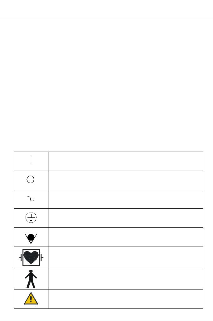
Safety Symbols
The International Electrotechnical Commission (IEC) has defined a set of graphic symbols for use on medical electronic equipment. The following symbols are used on KONTRON MEDICAL’ systems:
ON (Power)
OFF (Power)
AC line input
Protective earth (ground)
Equalization potential terminal
Type CF isolated E.C.G input, defibrillator proof (IEC 601 - 1)
Type B equipment (IEC 601 - 1)
This symbol generally means "Attention". Please consult the equipment documentation carefully before using any function labelled with this symbol
xx |
SIGMA 110/SIGMA 330 |
15.10.01 |

III.2.2. Environmental Safety
Electro-Magnetic Compatibility
This system complies with the EN60601-1-2 (Electro-Magnetic Compatibility). It is a Class B device.
Ultrasound units are designed to receive radio frequency (RF) energy and are, therefore, susceptible to other RF sources. As an example, other medical devices, information technology products or TV/Radio transmitters may all cause interference with the ultrasound system.
In the presence of RF interference, the physician must evaluate the image degradation and its diagnostic impact.
•Electrostatic discharge (ESD)
An electrostatic discharge is a short transient current flow. It may happen if electrostatically charged people touches a part of ultrasound system. ESD may causes white or black dots in 2D or TM mode, coloured dots in CFM and can be heard or seen as dots in Doppler mode. The effects created by ESD are not at all correlated with the ultrasound information. Therefore, they may be well differentiated from the true ultrasound echo.
•Burst
Bursts are short transient pulses on the mains power line. They may cause white or black dots in 2D or TM mode, coloured dots in CFM and can be heard or seen as dots in Doppler mode. The effects created by bursts are not correlated with the ultrasound information. Therefore, they may be well distinguishable from the true ultrasound echo.
•Immunity restriction
Electromagnetic fields in the environment of the ultrasound system may cause white or black patterns in 2D or TM mode, coloured patterns in CFM and can be seen as horizontal lines in Doppler mode. Especially in the Doppler modes (CW and PW), some lack of immunity may be observed in a narrow frequency band of 20 kHz at the used frequency and its multiples. Typically, the transducer acts like the reception antenna and the effects are stronger when it is applied to patient. In any case, the effects are not correlated with the ultrasound information; therefore, they may be well distinguishable from the true ultrasound echo.
Electro-Surgical Units (ESUs)
Electro surgical units or other devices that introduce radio frequency electromagnetic fields or currents into the patient, may interfere with the ultrasound image. An electro surgical device in use during ultrasound imaging will greatly distort the 2D image and render Doppler modalities useless.
Information about Reusing/Recycling
In this system, the packing materials are reusable and recyclable; the unit casings (plastic) and most of the cart components (plastic) are also recyclable.
The SIGMA 110 and SIGMA 330 contains electronic boards, batteries and tubes. Before you dispose the system, these boards, batteries and tubes must be removed and discarded according to local regulations or recycled where facilities exist. Contact your local KONTRON MEDICAL company or agent for further informations.
For battery disposal contact your local waste disposal facility.
15.10.01 |
GENERAL INFORMATION |
xxi |

III.2.3. Biocompatibility and Infection Control
Items in contact with patient
The probe and electrode materials that are in contact with patients, comply with the European applicable requirements (EN10993). No negative reactions to these materials have been reported.
Note
KONTRON probes and electrodes do NOT contain Latex.
Infection Control
Since probes and electrodes are intended to be used on intact skin, the use of this system has a very limited probability of being able to propagate infections; basic procedures as described later in this manual are sufficient for infection control.
III.2.4. Ultrasound Safety
Introduction
KONTRON MEDICAL has adopted the more recent requirements and recommendations established by the USA Food and Drug Administration and by the American Institute for Ultrasound in Medicine. The SIGMA 110/330 therefore, equipped with the Acoustic Output Display feature to provide the user with real-time, on-line information on the actual power of the system.
The following sections describe the rationale of this methodology. KONTRON MEDICAL recommends the use of the ALARA principle (see below), which is extensively covered in this manual.
Additionally to this operator manual you get the AIUM manual "Medical Ultrasound Safety" which covers the following topics more in detail: Bioeffects and biophysics, prudent use and implementing ALARA. Read it carefully before using the SIGMA 110/330.
Clinical Safety
In the USA, in more than three decades of use, there has been no report of injury to patients or operators from medical ultrasound equipment.
American Institute for Ultrasound in Medicine (AIUM)
Statement on Clinical Safety: October 1982, Revised March 1993 and October 1993
Diagnostic ultrasound has been in use for over 25 years. Given its known benefits and recognized efficacy for medical diagnosis, including use during human pregnancy, the American Institute of Ultrasound in Medicine herein addresses the clinical safety of such use:
No confirmed biological effects on patients or instrument operators caused by exposure at intensifies typical of present diagnostic ultrasound instruments have been reported. Although the possibility exists that such biological effects may be identified in the future, current data indicate that the benefits to patients deriving from the prudent use of diagnostic ultrasound outweigh the risks, if any, that may be present.
xxii |
SIGMA 110/SIGMA 330 |
15.10.01 |

The ALARA (As Low As Reasonably Achievable) principle is the guideline for prudent use; during an exam, the user should use for the shortest duration the least amount of acoustic output to obtain the necessary clinical information for diagnostic purposes.
Ultrasound Bioeffects
Although diagnostic ultrasound has an excellent history of safety, it has been known for a long time that ultrasound, at certain levels, can alter biological systems.
The AIUM Bioeffects Committee describes two fundamental mechanisms by which ultrasound may induce biological effects: non-thermal or mechanical mechanisms and thermal effects.
Non-thermal bioeffects, also, referred to as mechanical bioeffects, seem to be caused by the alternate expansion and contraction of tissue induced when ultrasound pressure waves pass through or near gas. The majority of these non-thermal interactions, also known as cavitation, deal with the generation, growth, vibration and possible collapse of micro bubbles within the tissue. The occurrence of cavitation depends on a number of factors, such as the ultrasonic pressure and frequency, the ultrasonic field (focused or unfocused, pulsed or continuous), the nature and state of the tissue and boundaries. Mechanical bioeffects are a threshold phenomenon, occurring only when a certain level of output is exceeded. However, the threshold level varies depending on the tissue. The potential for mechanical effects is thought to increase as peak rarefactional pressure increases, but decrease as the ultrasound frequency increases.
Although there have been no adverse mechanical bioeffects in humans from diagnostic ultrasound exposure, it is not possible to specify thresholds at which cavitation will occur in mammals.
Thermal Bioeffects are the rise in temperature of tissue when exposed to acoustic energy. The acoustic energy is absorbed by body tissue; absorption is the conversion of this energy into heat. If the rate of energy deposition in a particular region exceeds the ability to dissipate the heat, the local temperature will rise. The rise in temperature will depend on the amount of energy, the volume of exposure, and the thermal characteristics of the tissue.
On-Screen Real-Time Acoustic Output Display
Until recently, application-specific output limits established by the USA Food and Drug Administration (FDA) and the user‘s knowledge of equipment controls and patient body characteristics have been the means of minimizing exposure. Now, more information is available through a new feature, named the Acoustic Output Display. The Output Display provides users with information that can be specifically applied to ALARA. It eliminates some of the guess work and provides both an indication of what may actually be happening within the patient (i.e. the potential for bioeffects), and what occurs when system control settings are changed. This makes it possible for the user to get the best image possible while following the ALARA principle and thus to maximize the benefits/risks ratio.
The SIGMA 110/330 incorporates a real-time acoustic output display according to the AIUM/ NEMA “Standard for Real-Time Display of Thermal and Mechanical Acoustic Output Indices on Diagnostic Ultrasound Equipment” publication, adopted in 1992 by both institutions. This Output Display Standard is intended to provide on-screen display of these two indices, which are related to ultrasound thermal and cavitation mechanisms, to assist the user in making informed risk (i.e. patient exposure) / benefit (diagnostically useful information) decisions. Considering the type of
15.10.01 |
GENERAL INFORMATION |
xxiii |

exam, patient conditions and the case study level of difficulty, the system operator decides how much acoustic output to apply for obtaining diagnostically useful information for the patient; the thermal and mechanical indices real-time display is intended to provide information to the system operator throughout the examination so that exposure of the patient to ultrasound can be reasonably minimized while maximizing diagnostic information.
For systems with an Output Display, the FDA currently regulates only the maximum output. The SIGMA 110/330 has been designed to automatically default to the proper range of intensity levels for a particular application. However, within the SIGMA 110/330 limits, the user may override the application specific limits, if clinically required. The user is responsible for being aware of the output level that is being used. The SIGMA 110/330 real-time output display provides the user with relative information about the intensity level.
The Mechanical Index
The Mechanical Index (MI) is defined as the Peak Rarefactional Pressure in MPa (derated by a tissue attenuation coefficient of 0.3 dB/cm/MHz) divided by the square root of the probe central frequency in MHz.
With the MI, the user can keep the potential for mechanical bioeffects as low as reasonably achievable while obtaining diagnostically adequate images. The higher the index, the larger the potential. However, there is no level that indicates when Bioeffects is actually occurring: The Index is not intended to give an “alarm” but are an aid in implementing the ALARA principle.
The Thermal Index
The purpose of the Thermal Index (TI) is to keep the user aware of conditions that may lead to a temperature rise under certain defined assumptions. It is the ratio between the total acoustic power to the power required to raise tissue temperature by 1°C, estimated on Thermal Models.
There are currently three Thermal Indices (each based on a specific Thermal Model) used to estimate temperature rise whether at the surface, within the tissues, or at the point where the ultrasound is focusing on bone:
1.The Soft Tissue Thermal Index (TIS) provides information on temperature increase within soft homogeneous tissue.
2.The Cranial Bone Thermal Index (TIC) indicates temperature increase of bone at or near the surface, as may occur during a cranial exam.
3.The Bone Thermal Index (TIB) provides information on temperature increase of bone at or near the focus after the beam has passed through soft tissue.
As with the Mechanical Index, the Thermal Indices are relative indicator of temperature rise: a higher value represents a higher temperature rise; they indicate that the possibility for an increase in temperature exists and they provide a relative magnitude that can be used to implement ALARA.
The SIGMA 110/330 Acoustic Output Display
xxiv |
SIGMA 110/SIGMA 330 |
15.10.01 |

The SIGMA 110/330 displays the Acoustic Output Indices during live scanning to the right of the screen, together with the transmit power setting and other technical data. The following abbreviations are used:
Index |
Abbreviation |
Mechanical Index |
MI |
Soft Tissue Thermal Index |
TIS |
Cranial Bone Thermal Index |
TIC |
Bone Thermal Index |
TIB |
The Output Display is organized to provide meaningful information to implement ALARA without “distracting” the user with unnecessary data. Each time a user selects a new probe a choice of applications is provided (Radio, Vasc., Ob/Gyn, Cardio); depending on the selection, the system will default the appropriate indices.
Note
Index values below 0.4 are displayed by this system as <0.4. Indices are displayed in 0.2 increments
To optimize ALARA, index values equal or higher than 0.4 are displayed even if the maximal index value does not exceed 1.0.
The SIGMA 110/330 does not provide combination modes (i.e. modes used simultaneously, such as real-time 2D and Doppler), but can display a tracing (Doppler or TM-Mode) with a reference 2D (frozen or periodically updated). The index for the active mode is indicated.
The SIGMA 110/330 Output Default Settings
System default settings depend upon the probe, the mode of operation and the application which is selected after selecting a probe. The SIGMA 110/330 defaults the transmit power to obtain output levels that are below the historic Ispta limits established by the FDA for the selected application.
Methodology and Accuracy of Display
The displayed indices values must be interpreted as relative information to help the user to achieve the ALARA principle.
Initial data are derived from laboratory measurements based on the AIUM standard. Then the indices are calculated beginning from these measurements according to the AIUM/NEMA “Standard for Real-Time Display of Thermal and Mechanical Acoustic Output Indices on Diagnostic Ultrasound Equipment” publication. Many of the assumptions used for measurements and calculation are conservative in nature. The measured water tank values are derated using the conservative attenuation coefficient established by the FDA (0.3 dB/cm/MHz). Over-estimation of actual In-Situ exposures is thus part of the calculation process.
A number of factors influence the estimation of the accuracy of the displayed indices, the most significant ones being the variability between probes and the laboratory measurements accuracy
15.10.01 |
GENERAL INFORMATION |
xxv |

(hydro phone, operator, algorithms, etc.) itself, while variability of the system pulser and efficiency is a minor contributor.
The accuracy of the measurement of the centre frequency is estimated to be ±2%, of the acoustic pressure to be ±16%, of the acoustic power to be ±10% and of the acoustic intensity to be ±32%.
The accuracy estimate, based on the variability range of probes and systems, and on the inherent modelling and the above mentioned measurements errors, ranges from ±30% for the MI index to ±50% for the TI index.
The SIGMA 110/330 Maximum Acoustic Output
As per the AIUM standard, the tables in Appendix M: Acoustic Output Tables list the maximum TI (Thermal Index) and MI (Mechanical Index) values for each probe and mode of operation.
The system screens display the recently adopted MI, which is now considered a better relative indicator of non-thermal bioeffect mechanisms. The SIGMA 110/330 maximal MI is 1.9 which FDA has recognized as equivalent to pre-amendments Isppa limits.
The SIGMA 110/330 maximum output for Ispta is limited to the preamendments FDA limit for peripheral vascular applications, which is 720 mW/cm2.
The maximum output for a given probe can be less than the system limit, since the maximum depends on a variety of elements (crystal efficiency, mode of operation etc.). It is normally reached with the Vasc. setup, at minimum depth or maximum PRF and in CFM with the smallest CFM window size.
All terms are defined in Section III.2.6, “Glossary and definition of terms,” on page xxviii
The SIGMA 110/330 Acoustic Output Controls
Control features may be divided into three categories:
1.controls which directly affect the intensity (direct controls)
2.controls which indirectly affect the intensity (indirect controls)
3.controls which do not affect the intensity, such as the gains and the processing curves.
Controls which directly affect the intensity:
•the Application selection, which establishes the appropriate range of intensities (see Maximum Output Section)
•the Energy control for Doppler modes, which allows to increase or decrease the output intensity within the range of the selected application.
Controls which indirectly affect the intensity:
This category includes controls which change several aspects of the transmitted ultrasonic field rather than the intensity. Intensity is affected because of the field variations. Each mode has its
xxvi |
SIGMA 110/SIGMA 330 |
15.10.01 |

own pulse repetition frequency (PRF) and intensity level; moreover, for each mode, a number of parameters will indirectly affect the transmitted field.
2D
The SIGMA 110/330 allows the user to set the transmit focal point which will affect the indices by varying the beam profile. Generally, higher MI‘s will occur with farer focal points. If more than one transmit focal point is activated, MI values will correspond to the zone with the largest value.
TM
In TM mode, the transmitted field is only affected by the transmit focal point and the frequency. If M-Mode is displayed with a 2D and the 2D is updated, the system may shows always the index for the active mode (MI for 2D, TI for TM mode)
CFM
The TI may be increased by any control which increases the system frame rate:
•reducing the CFM window size
•increasing the CFM PRF
Another variable factor is the CFM frequency; the outcome in terms of transmitted field is marginal and largely unpredictable.
Pulsed Wave Doppler
In PW, the transmit energy is adjusted automatically when changing gatesize or PRF to be constant. Therefore the TI is constant for all settings of gatesize and PRF. The only “variable” factor is the Doppler frequency; the outcome in terms of transmitted field is marginal and largely unpredictable.
Continuous Wave Doppler
In CW, the only “variable” factor is the Doppler frequency. Most probes provide Doppler at more than one frequency; the outcome in terms of transmitted field is marginal and largely unpredictable. The user can vary the spectral velocity range; this does NOT, however, change the system‘s PRF.
Implementing ALARA with the SIGMA 110/330
Prudent use implies that during an exam the user should use for the shortest time the least amount of acoustic output to obtain the necessary clinical information for diagnostic purposes. In other words, your goal is to keep the TI and the MI indices as low as possible for the shortest time while obtaining the necessary clinical information.
This section does not cover the patient and technique factors which may influence the indices such as the patient body size, the tissue perfusion characteristics, the presence or the absence of fluid, etc.
• select the appropriate application when you select the probe
15.10.01 |
GENERAL INFORMATION |
xxvii |

•depending on the patient characteristics and the type of exam (see Intended Use Section) select the appropriate probe and frequency
•use the system capabilities to preset the SIGMA 110/330 to default each mode according to your needs or specific applications; this will reduce the need for real-time interactions and help you obtain useful images quickly thus reducing ultrasound exposure
•start scanning with a low output level and optimize the focusing, the gains and all other system adjustments; if this is not adequate for diagnostic purposes, then increase the output level
•use the Output Display feature to guide your settings; remember that the indices do not consider TIME exposure: the higher your indices, the shorter should be the patient exposure
Which index when
In cardiology, vascular and general purpose (abdominal, small parts) exams MI is the primary concern in 2D mode, while TIS is the principle index in CFM and Doppler.
In Ob/Gyn the TIB should be considered when scanning a second or third trimester fetus, while the TIS is more reliable for earlier exams.
The TIB is a better predictor during neonatal head studies, while the TIC is more significant in adult transcranial studies.
III.2.5. Measurement Accuracy on SIGMA 110/330
This is thoroughly discussed in Chapter 1.7.11 on page 1-49 and Chapter 1.8.13 on page 1-60.
III.2.6. Glossary and definition of terms
ÞIn Situßintensities calculations
When determining the possible effects of the ultrasound beam on tissue, the intensity encountered at the tissue site must be calculated. Because of attenuation of the beam within the body, the intensity at the tissue site (“in situ”) may be 10 to 100 times less than if it was measured at the same location in water. The amount of attenuation from experience by an ultrasound beam as it travels through the body tissue is determined by three factors:
1.Type of tissue along the beam path
2.Frequency of the ultrasound energy
3.Distance covered by the beam
In order to achieve a conservative approximation of attenuation due to these three factors, the FDA requires the application of the following formula:
Id = Iw exp (-0.23 a f z)
•Id is the estimated “In Situ” intensity at the tissue site
•Iw is the intensity measured in water at the distance “z”, measured in cm
•a is the attenuation coefficient expressed in dB/cm/MHz
•f is equal to the acoustic frequency in MHz of the ultrasound beam
xxviii |
SIGMA 110/SIGMA 330 |
15.10.01 |
Loading...