


ADD2-LVDS-DUAL
ADD2-LVDS
KTD-00711-D Public User Manual Date: 2008-09-16 Page 1 of 13
User Manual
for the
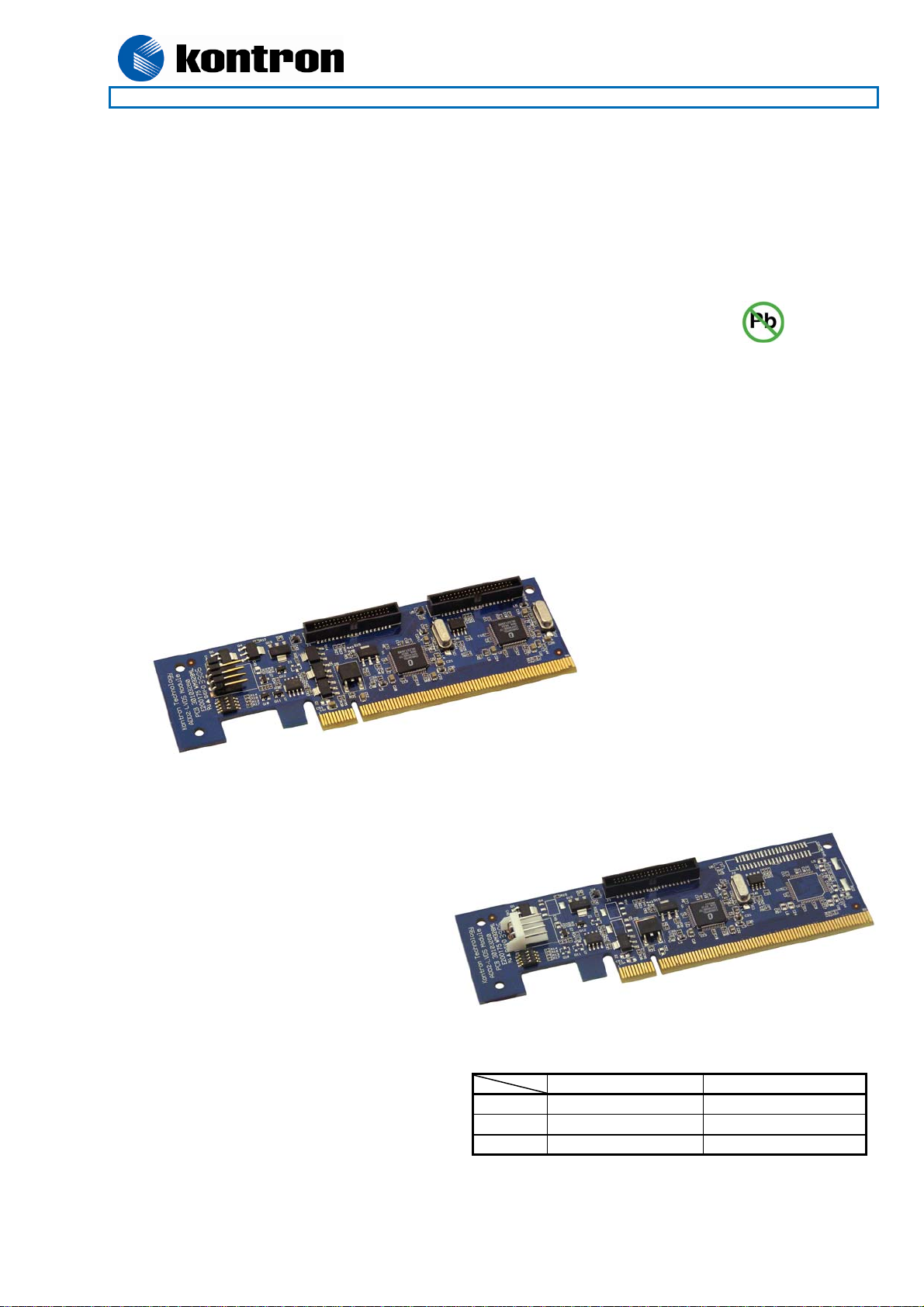
820950 ADD2-LVDS-Dual card
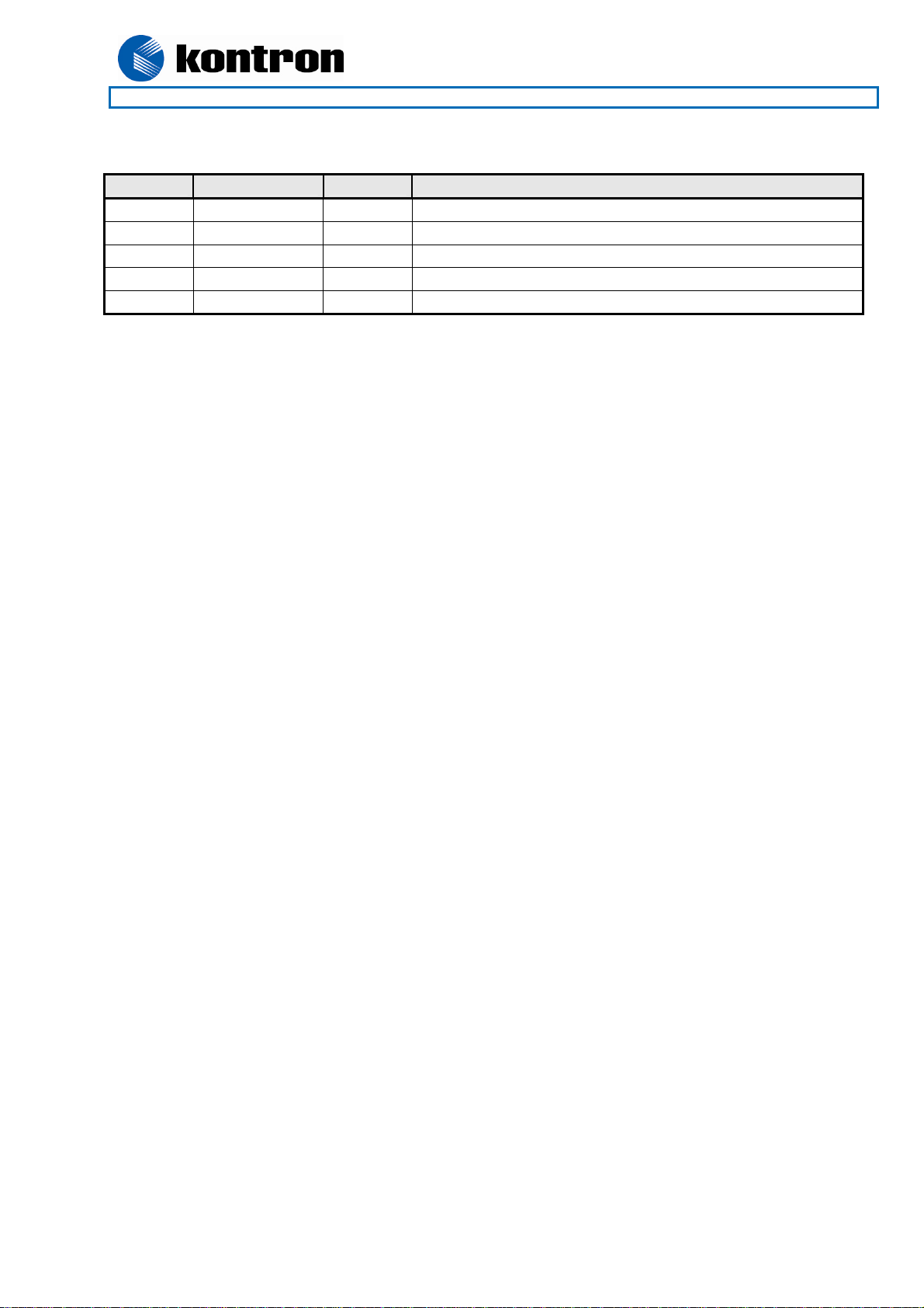
820953 ADD2-LVDS-Single card
AGP Digital Display second generation card with Low Voltage Differential Signaling Transmitter
Designed primarily for 986LCD-M family and KT965/Flex motherboards
820950 ADD2-LVDS-Dual
820953 ADD2-LVDS-Single
ADD2-LVDS-Dual ADD2-LVDS-Single
Part no. 820950 820953
PCB no. 30103260 30103260
Ass. no. 68600002 68400000
ADD2-LVDS
KTD-00711-D Public User Manual Date: 2008-09-16 Page 2 of 13
Document revision history.
Revision Date By Comment
D Sept. 16th 2008 MLA Page 7, “PWR connector” text improved.
C Sept. 4th, 2007 MLA MB specific configuration added to Installation Guide.
B Aug. 20th, 2007 MLA 820953 Picture added. Minor layout changes.
A Mar. 13th , 2007 MLA Add ADD2-LVDS-Single
0 Jan. 19th , 2007 MLA Preliminary version.
Copyright Notice:
Copyright © 2007, KONTRON Technology A/S, ALL RIGHTS RESERVED.
No part of this document may be reproduced or transmitted in any form or by any means, electronically or
mechanically, for any purpose, without the express written permission of KONTRON Technology A/S.
Trademark Acknowledgement:
Brand and product names are trademarks or registered trademarks of their respective owners.
Disclaimer:
KONTRON Technology A/S reserves the right to make changes, without notice, to any product, including
circuits and/or software described or contained in this manual in order to improve design and/or performance.
Specifications listed in this manual are subject to change without notice. KONTRON Technology assumes no
responsibility or liability for the use of the described product(s), conveys no license or title under any patent,
copyright, or mask work rights to these products, and makes no representations or warranties that these
products are free from patent, copyright, or mask work right infringement, unless otherwise specified.
Applications that are described in this manual are for illustration purposes only. KONTRON Technology A/S
makes no representation or warranty that such application will be suitable for the specified use without
further testing or modification.

ADD2-LVDS
KTD-00711-D Public User Manual Date: 2008-09-16 Page 3 of 13
Life Support Policy
KONTRON Technology’s PRODUCTS ARE NOT FOR USE AS CRITICAL COMPONENTS IN LIFE
SUPPORT DEVICES OR SYSTEMS WITHOUT EXPRESS WRITTEN APPROVAL OF THE GENERAL
MANAGER OF KONTRON Technology A/S.
As used herein:
1. Life support devices or systems are devices or systems which, (a) are intended for surgical implant into
body, or (b) support or sustain life and whose failure to perform, when properly used in accordance with
instructions for use provided in the labeling, can be reasonably expected to result in significant injury to
the user.
2. A critical component is any component of a life support device or system whose failure to perform can be
reasonably expected to cause the failure of the life support device or system, or to affect its safety or
effectiveness.
KONTRON Technology Technical Support and Services
If you have questions about installing or using your KONTRON Technology Product, check this User’s
Manual first – you will find answers to most questions here. To obtain support, please contact your local
Distributor or Field Application Engineer (FAE).
Before Contacting Support: Please be prepared to provide as much information as possible:
ADD-On Board
1. Type.
2. Part-number (Number starting with “68”).
Configuration
1. Motherboard Type
2. BIOS Revision (Find the Version Info (BIOS ID) in the BIOS Setup Menu)
3. BIOS Settings different than Default Settings (Display related settings).
4. O/S Make and Version.
5. Graphic Driver Version numbers.
6. Attached LCD Panel(s) etc.

ADD2-LVDS
KTD-00711-D Public User Manual Date: 2008-09-16 Page 4 of 13
Table of contents:
INTRODUCTION................................................................................................................................................5
MECHANICAL DRAWING.................................................................................................................................5
FUNCTIONAL DIAGRAM..................................................................................................................................6
CONNECTOR POSITION..................................................................................................................................7
CONNECTOR DESCRIPTION...........................................................................................................................7
INSTALLATION GUIDE.....................................................................................................................................9
ELECTRICAL SPECIFICATION......................................................................................................................10
APPENDIX: HOW TO REMOVE LVDS CONNECTOR ..................................................................................11
APPENDIX: THE 820971 LDI EVALUATION KIT ..........................................................................................12
 Loading...