

Page 1

PageScope
Network Setup 3.0
User Manual
Page 2

Foreword
Welcome
Thank you for using KONICA MINOLTA PageScope Network Setup.
PageScope Network Setup is utility software which allows simple
network setup of devices such as printers. It allows setup of devices on
networks connected using TCP/IP or IPX protocol to be handled
together.
PageScope Network Setup supports the following functions.
• Displays a list of devices on the network.
• Allows a user to verify and change the network and print settings for
devices.
• Allows setup for peer-to-peer printing.
• Accesses the Web settings page in the device.
• Allows monitoring of the device status.
• Displays alert and output tray information for a device.
Trademark Acknowledgements
KONICA MINOLTA and KONICA MINOLTA logo are trademarks or
registered trademarks of KONICA MINOLTA HOLDINGS, INC.
PageScope is a trademark or a registered trademark of KONICA
MINOLTA BUSINESS TECHNOLOGIES, INC.
Ethernet is a registered trademark of Xerox Corporation.
Microsoft, Windows, and Windows NT are registered trademarks or
trademarks of Microsoft Corporation in the United States and/or other
countries.
Novell and NetWare are registered trademarks of Novell, Inc., in the
United States and other countries.
All other product names are trademarks or registered trademarks of
their respective holders.
Copyright
TECHNOLOGIES, INC. All rights reserved.
The information contained in this manual is subject to change
without notice.
2002 KONICA MINOLTA BUSINESS
©
i
Page 3

Contents
CONTENTS
1 System Requirements ................................ 1
2 Installing and Starting PageScope
Network Setup ............................................. 2
2.1 Installing PageScope Network Setup........... 2
2.2 Starting PageScope Network Setup............. 2
2.3 Uninstalling PageScope Network Setup...... 3
2.3.1 For Windows 95/98/Me/NT/2000........... 3
2.3.2 For Windows XP.................................... 3
3 Browsing Network Devices ........................ 4
3.1 Screen Configuration .................................... 4
3.2 Verifying Device Setup Status ...................... 8
3.3 Displaying the Device Alert Property........... 9
3.4 Displaying Device Output Tray
Information ................................................... 10
3.5 Configuring a Device with PageScope
Network Setup.............................................. 11
ii
Page 4

Contents
4 Changing the Device Setup...................... 12
4.1 Configuring Device Information ................. 12
4.2 Configuring TCP/IP...................................... 14
4.3 NetWare Print Setup .................................... 16
4.3.1 Setting up the Print Server ................ 17
4.3.2 Selecting the Mode ............................. 18
4.3.3 Selecting the Print Queue .................. 20
4.3.4 Selecting Users for Event
Notification .......................................... 22
4.3.5 Verifying the Setup ............................. 23
5 Peer-to-peer Print Setup ........................... 25
5.1 TCP/IP Peer-to-peer Printing....................... 25
5.1.1 Configuring for TCP/IP Peer-to-peer
Printing ................................................ 25
5.1.2 Configuring for TCP/IP Peer-to-peer
Printing by Specifying the Device
Manually............................................... 27
5.2 IPX Peer-to-peer Printing............................. 28
5.2.1 Configuring IPX Peer-to-peer P
rinting................................................... 28
5.2.2 Configuring for IPX Peer-to-peer
Printing by Specifying the Device
Manually............................................... 30
5.3 After Creating the Peer-to-peer Port .......... 31
iii
Page 5

Contents
6 Option Setup ............................................. 33
6.1 Selecting a Protocol .................................... 33
6.2 Specifying the Search Range ..................... 34
6.3 Specifying BOOTP ....................................... 36
6.4 Specifying Polling Settings......................... 38
6.5 Changing the Password .............................. 39
Appendix Glossary ....................................... 40
iv
Page 6

1 System Requirements
1 System Requirements
The following are the minimum system requirements for installing
PageScope Network Setup.
OS*(1)
Browser
NetWare Client*(2)
Protocol*(3)
*(1) We recommend you to use the latest version service packs when using
Windows NT 4.0 or Windows 2000.
*(2) Although this utility can work without NetWare, it is required when you
set up NetWare.
*(3) The tools provided by this utility differ according to the type of protocol
supported on the user network environment.
- Windows 95/98/Me
- Windows NT 4.0
- Windows 2000
- Windows XP
- Internet Explorer 4.0 or later
- Novell NetWare Client 32 (latest version)
- TCP/IP
- IPX/SPX
1
Page 7

2 Installing and Starting PageScope Network Setup
2 Installing and Starting PageScope
Network Setup
2.1 Installing PageScope Network Setup
Use the following procedure to install PageScope Network Setup.
1. Place the CD-ROM into your computer’s CD-ROM drive.
2. Start up the installation program. (setup.exe)
3. Follow the instructions that appear on your computer screen to
proceed with the installation.
The following is the default installation location used by the
installer.
C:\Program Files\KONICA MINOLTA\PageScope
Network Setup
The installer provides you with an opportunity to specify a
different location, if you want.
2.2 Starting PageScope Network Setup
1. Click
Start
Network Setup
In the case of Windows XP, click
KONICA MINOLTA
PageScope Network Setup
2. When the
Programs
→
→
Login Password
→
PageScope Network Setup
PageScope Network Setup
→
KONICA MINOLTA
PageScope
→
.
start
All Programs
→
→
→
.
dialog box appears, type in the
password.
Note
• The default password is “admin”.
• For details on changing the password, refer to
Password”
• When you start up PageScope Network Setup, it searches for devices
on the network. The search procedure can take anywhere from a few
seconds to 20 or 30 seconds or more. Wait for the search procedure to
complete before trying to do anything else.
.
“6.5 Changing the
2
Page 8

2 Installing and Starting PageScope Network Setup
2.3 Uninstalling PageScope Network Setup
2.3.1 For Windows 95/98/Me/NT/2000
1. Click
2. Double-click the
3. On the
KONICA MINOLTA PageScope Network Setup
programs, and then click the
In the case of Windows 2000, click
Programs
Setup
4. Follow the instructions that appear on the screen to complete the
uninstall procedure.
2.3.2 For Windows XP
1. Click
2. Double-click the
3. On the
MINOLTA PageScope Network Setup
and then click the
4. Follow the instructions that appear on the screen to complete the
uninstall procedure.
→
Start
Add/Remove Programs Properties
Settings
, click
, and then click the
→
Start
Add or Remove Programs
Control Panel
→
Control Panel
Add/Remove Programs
Add/Remove
Change or Remove
KONICA MINOLTA PageScope Network
Change/Remove
.
Add or Remove Programs
dialog box, select
in the list of programs,
Change/Remove
button.
.
icon.
dialog box, select
in the list of
button.
button.
icon.
KONICA
3
Page 9
3 Browsing Network Devices
3 Browsing Network Devices
This section explains the contents of PageScope Network Setup
screens.
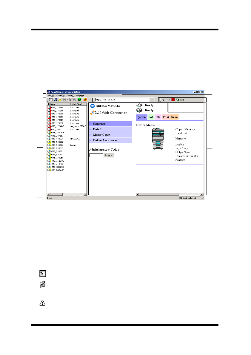
3.1 Screen Configuration
➀
➁
➂
➃
➀
Menu bar
Clicking on a menu pulls it down so you can access its commands.
➁
Toolbar (for the device list)
The toolbar provides one-click access to often-used PageScope
Network Setup operations.
If you cannot see the toolbar on the display, select
View
menu.
Toolbars
➆
➅
➄
on the
...Displays the properties of the device selected in the device list.
...Displays a dialog box for changing the settings of the device
selected in the device list.
...Displays alert information for the device selected in the device
list.
4
Page 10
3 Browsing Network Devices
...Displays output tray information for the device selected in the
device list.
...Quits PageScope Network Setup.
...Displays a dialog box for configuring peer-to-peer printing.
... Refreshes the device list.
...Displays on-line help.
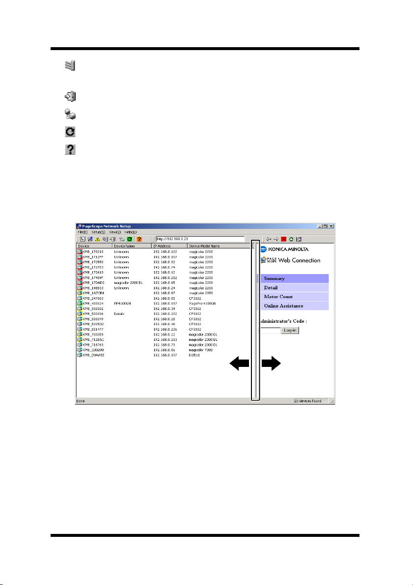
➂
Device list
This list show devices detected on the network.
To change the width of the device list, drag the border between the
device list and browser display area.
5
Page 11

3 Browsing Network Devices
Device
This is the device icon and device name. The icon that appears
differs according to the protocol used for connecting the device.
...Device connected using TCP/IP
...Device connected using IPX
Devices connected using both TCP/IP and IPX will be displayed
with the TCP/IP icon.
The background color of the icon indicates the device status.
No color: Ready
Green: Printing
Yellow: Alert
Red: Error
The device status is updated every 30 seconds (default setting).
The interval can be changed with the polling settings.
See 6.4 Specifying Polling Settings for details on changing the
polling interval.
Device Name
This is the device name for management purposes.
IP Address
This is the IP address allocated to the device.
Device Model Name
This is the device model name.
• Select
• See 6 Option Setup for details about configuring the device
➃
Status bar
When you move the mouse pointer to a toolbar button, the status bar
displays an explanation of the button’s function.
Device Search
search and display the latest network information on the device list.
search operation.
from the
menu to perform a new device
File
6
Page 12

3 Browsing Network Devices
If you cannot see the status bar on the display, select
the
➄
Browser display area
This area displays the built-in Web setup page for the device
selected in the device list.
➅
Toolbar (for the browser display area)
The toolbar contains buttons for performing various operations in
the browser display area.
➆
URL field
This field displays the URL of the device selected in the device list.
menu.
View
...Returns to the previously displayed page.
...Advances to the next page after the pages have been scrolled
through using the button.
...Closes the Web setup page display.
...Refreshes the contents of the Web setup page.
...Displays the current Web setup page in the standard Web
browser installed on your system.
Statusbars
on
7
Page 13
3 Browsing Network Devices
3.2 Verifying Device Setup Status
Verify the current device setup status as follows.
1. On the device list, click on the icon for the device whose setup
status you want to verify.
2. Select
You could also click the toolbar button.
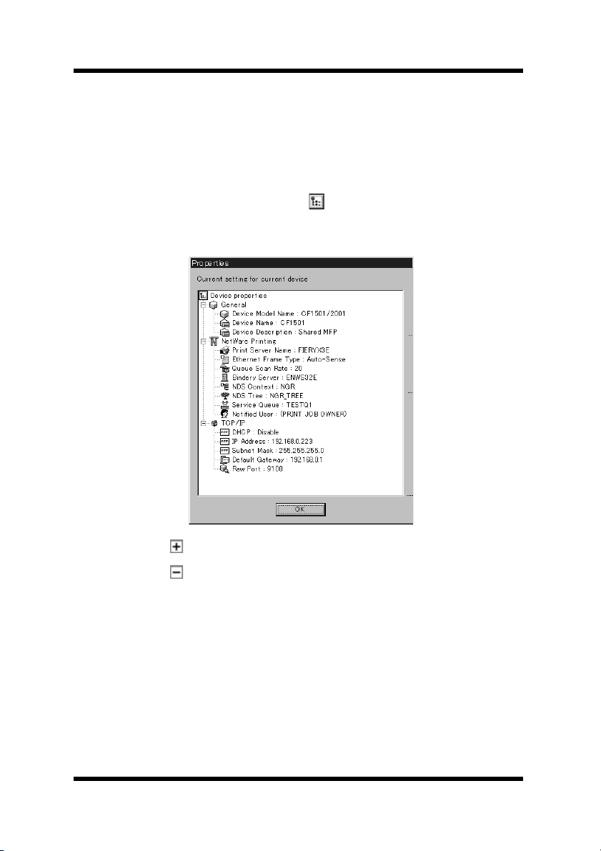
This displays the
status for the device.
Device Property
on the
Properties
menu.
File
dialog which shows the current setup
• Click a button on the tree to expand an item.
• Click a button on the tree to collapse an item.
The
Properties
General
Displays the settings for managing the device. See 4.1 Configuring
Device Information for details about changing this setup.
NetWare Printing
Displays the setup for device NetWare printing. See 4.3
NetWare Print Setup for details about changing this setup.
dialog contains the following information.
8
Page 14
3 Browsing Network Devices
TCP/IP
Displays the setup for device TCP/IP. See 4.2 Configuring TCP/
IP for details about changing this setup.
3. After you are finished, click the
button to close the dialog box.
OK
Note
• You cannot verify the following attributes unless you have NetWare
Client 32 installed on your system and log in to the NetWare server.
- NetWare Service Queue
- NetWare Notify User
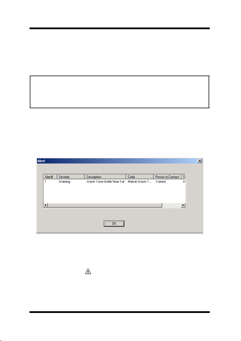
3.3 Displaying the Device Alert Property
Follow the procedure described below to display the alert information
for the device selected in the device list.
1. In the device list, click the icon of the device whose alert
information you want to display.
2. Select
click the toolbar button.
Device Alert Property
on the
File
menu. You could also
9
Page 15
3 Browsing Network Devices
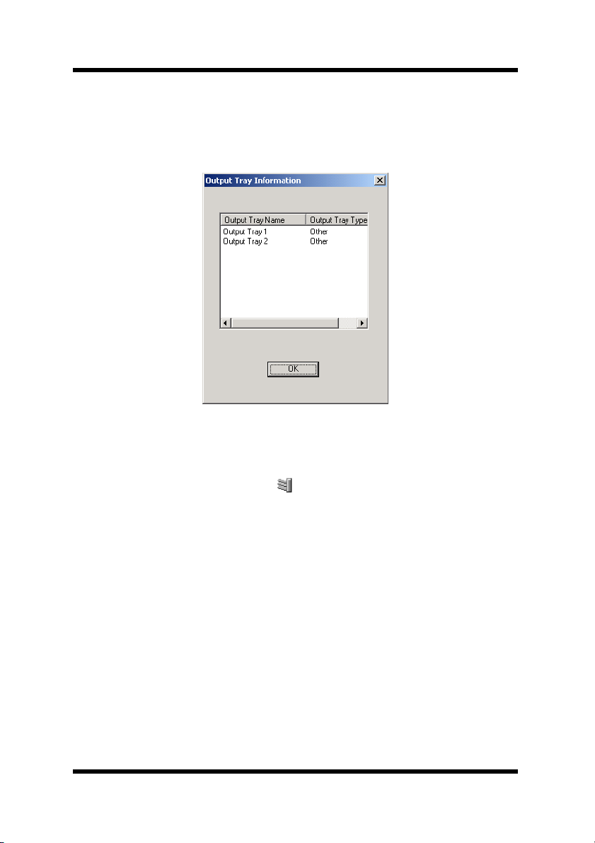
3.4 Displaying Device Output Tray Information
Follow the procedure described below to display output tray
information for the device selected in the device list.
1. In the device list, click the icon of the device whose output tray
information you want to display.
2. Select
Device Output Tray Information
could also click the toolbar button.
on the
File
menu. You
10
Page 16

3 Browsing Network Devices
3.5 Configuring a Device with PageScope
Network Setup
This section describes the procedure for network printer setup with
PageScope Network Setup.
First check the following points relating to your network environment.
Check with your network administrator for details about the network
environment.
• The protocol used on the network (TCP/IP or IPX)
• Connection format of the device (peer-to-peer or via server)
Use one of the following procedures to configure the device. The
procedure you should use depends on the network connection.
For peer-to-peer printing with TCP/IP connection:
1. Verify the device setup status. See 3.2 Verifying Device Setup
Status.
2. Setup the device TCP/IP connection. See 4.2 Configuring TCP/
IP.
3. Setup peer-to-peer printing. See 5.1 TCP/IP Peer-to-peer
Printing.
For peer-to-peer printing with IPX connection:
1. Verify the device setup status. See 3.2 Verifying Device Setup
Status.
2. Setup peer-to-peer printing. See 5.2 IPX Peer-to-peer Printing.
For printing via a NetWare print server:
1. Verify the device setup status. See 3.2 Verifying Device Setup
Status.
2. Setup NetWare printing. See 4.3 NetWare Print Setup.
After setting up the printer, specify the port in the printer driver
properties, and execute the print command. For details about printing,
see your printer manual.
11
Page 17

4 Changing the Device Setup
4 Changing the Device Setup
Use the
The following are the settings that can be configured when changing a
device setup.
• Device Information
• TCP/IP
• NetWare Print
Device Setup
dialog to change a device setup.
4.1 Configuring Device Information
Perform the following steps to configure device information.
1. On the device list, click the icon of the device whose information
you want to configure.
2. Select
3. Click the
Device Setup
Setup
dialog box.
You could also click the toolbar button.
General
on the
tab.
Setup
menu to display the
Device
12
Page 18

4 Changing the Device Setup
You can configure and view the following items on the
General
tab.
Device Model Name
This is the device model name. You cannot change the device
model name here.
Device Name
This is the device management name. You can type up to 16
characters into the text box to input a new name. However, if the
existing device management name exceeds 16 characters, you
can type up to 255 characters for a new name.
Device Description
This is a description of the device. You can type up to 16
characters into the text box to input a new description. However,
if an existing description of the device exceeds 16 characters,
you can type up to 255 characters for a new description.
4. After you are finished making the settings you want, click the
OK
button. This displays the device properties with the changed
settings in blue.
5. If the settings are correct, click the
OK
button.
The community name input dialog box appears only if the SNMP
community name has been changed to something other than the default
name. Type in the community name and then click
OK
.
13
Page 19

4 Changing the Device Setup
4.2 Configuring TCP/IP
Perform the following steps to configure TCP/IP.
1. On the device list, click the icon of the device you want to
configure.
2. Select
Setup
Device Setup
dialog box.
You could also click the toolbar button.
3. Click the
TCP/IP
tab.
on the
menu to display the
Setup
Device
You can configure the following items on the
TCP/IP
IP Address Setup
• Obtain an IP address automatically
If this option is selected, the IP address is acquired from either
the DHCP server or the BOOTP server.
- DHCP Select to obtain the IP address from the
DHCP server.
- BOOTP Select to obtain the IP address from the
BOOTP server.
14
tab.
Page 20

4 Changing the Device Setup
• Specify an IP address manually
When this option is selected, you can set the IP address
manually. Enter the following values.
- IP Address Device IP address
- Subnet Mask Subnet mask used with the network
- Default Gateway Default IP router address for the device
RAW Port Number
Enter the RAW port number used for peer-to-peer printing.
4. After making the settings you want, click the
displays the device properties with the changed settings in blue.
5. If the settings are correct, click the
OK
button.
A message asking for confirmation to continue the setup appears.
button. This
OK
6. Click the
Yes
button.
A message stating that it is necessary to reset may appear.
For equipment that can be reset, the following dialog appears.
7. If there are no problems with resetting now, click the
Reset Now
button.
Note
• The community name input dialog box appears only if the SNMP
community name has been changed to something other than the default
name. Type in the community name and then click
• If both DHCP and BOOTP are selected, DHCP is given priority.
OK
.
15
Page 21

4 Changing the Device Setup
4.3 NetWare Print Setup
Note
• You must have NetWare Client 32 installed on your system in order to
setup for NetWare printing.
• NetWare supervisor privileges are required in order to change the
NetWare Print Setup. You must login to the NetWare network with
supervisor privileges in order to configure NetWare for printing.
• You must have IPX protocol installed on your device in order to
configure a NetWare print setup.
• If you have already configured a NetWare print setup with another tool,
the existing configuration will be deleted when you complete this setting.
Perform the following steps to configure a device for NetWare printing.
1. On the device list, click the icon of the device you want to
configure.
2. Select
Setup
Device Setup
dialog box.
You could also click the toolbar button.
3. Click the
NetWare Printing
4. Perform the following steps.
• Set up the print server. See 4.3.1 Setting up the Print Server.
• Select the mode. See 4.3.2 Selecting the Mode.
• Set up the print queue. See 4.3.3 Selecting the Print Queue.
• Select users for event notification. See 4.3.4 Selecting Users for
Event Notification.
• Verify the setup. See 4.3.5 Verifying the Setup.
on the
menu to display the
Setup
tab.
Device
Note
• Clicking the
configuration. Downloading can take anywhere from a few seconds to
20 or 30 seconds or more. Wait for the download procedure to
complete before trying to do anything else.
• The community name input dialog box appears only if the SNMP
community name has been changed to something other than the default
name. Type in the community name and then click OK.
NetWare Printing
tab downloads the device
16
Page 22

4 Changing the Device Setup
4.3.1 Setting up the Print Server
Perform the following steps to set up the print server for NetWare
printing.
1. Type up to 26 characters into the
print server name.
Normally, you should leave the following items set to their initial
defaults. Change these settings only when absolutely necessary for
some reason.
Print Server Name
box for the
Print Queue Scan Rate
Type in the interval, in seconds, to specify how often the print
server should check the queue.
Ethernet Frame Type
Specify the Ethernet frame type.
2. After you are finished configuring the setup, click the
Next
button.
Note
• To configure a NetWare print setup, the server must be bound to at least
one IPX frame.
17
Page 23

4 Changing the Device Setup
4.3.2 Selecting the Mode
Use the procedures in this section to select the server you want to
configure as the print server, or the NDS context.
If you are using bindery service (NetWare 3.x):
1. Put a check mark into the
NetWare 3.x Bindery Server
check
box.
2. Click the button to display the
Mode Select
dialog box, which
shows a list of servers on the NetWare network.
3. Select the server you want to configure as the print server, and then
click the
4. When everything is the way you want, click the
OK
button.
Next
button.
If you are using NDS (NetWare 4.x or lator):
1. Put a check mark into the
2. Click the button to display the
NetWare 4.x NDS Context
Mode Select
dialog box, which
check box.
shows a list of NDS trees on the NetWare network.
3. Select the NDS tree you want to setup as the print server, and then
click the
OK
button.
18
Page 24

4 Changing the Device Setup
4. Click the button to display the
Mode Select
dialog box, which
shows a list of NDS contexts for the tree you selected.
5. Select the NDS context to setup the print server, and then click the
button.
OK
6. When everything is the way you want, click the
Next
button.
Note
• If you are logged on to the NetWare network without supervisor
privileges, the NetWare login screen will appear after you finish
configuring the setup. If this happens, type in the supervisor login
name and password, and then click OK.
19
Page 25

4 Changing the Device Setup
4.3.3 Selecting the Print Queue
Use one of the following procedures to select the print queue for the
print job.
To select an existing print queue:
1. Use the upper left box to select an NDS tree (in the case of NDS)
or a server (in the case of bindery service). This displays a list of
print queues for the selected NDS context (in the case of NDS) or
server (in the case of bindery service) in the list on the left.
2. In the list on the left, select the print queue you want to use, and
then click the
the right.
3. To remove a print queue from the list on the right, select it and
then click the
4. When everything is the way you want, click the
Append
Delete
button to add the print queue to the list on
button.
Next
button.
20
Page 26

4 Changing the Device Setup
To create a new print queue:
1. Use the upper left box to select an NDS tree (in the case of NDS)
or a server (in the case of bindery service).
2. Click the
Create New
button to display the
Add Queue
box.
3. Type up to 26 characters for the name you want to assign to the
new print queue into the
4. Use the
Volume
list to select a volume for the new print queue.
Name
box.
Note that you cannot change the volume for creating the new print
queue when using bindery service.
5. When using NDS only, type the NDS context name into the
Context
box. Note that you cannot input a NDS context name
when using bindery service.
6. When everything is the way you want, click the
OK
dialog
button.
21
Page 27

4 Changing the Device Setup
4.3.4 Selecting Users for Event Notification
Perform the following steps to select users for notification of events
occurring on the device.
1. Use the upper left box to select an NDS tree (in the case of NDS)
or a server (in the case of bindery service). This displays a list of
users for the selected NDS context (in the case of NDS) or server
(in the case of bindery service) in the list on the left.
2. In the list on the left, select a user to be notified and then click the
Append
3. To remove a user from the list on the right, select it and then click
the
4. To notify the user who originated the print job of an event, put a
check mark into the box next to
so causes the
right.
5. When everything is the way you want, click the
button to add the user to the list on the right.
Delete
button.
PRINT JOB OWNER
Notify owner of print job
icon to appear in the list on the
Next
. Doing
button.
22
Page 28

4 Changing the Device Setup
4.3.5 Verifying the Setup
The NetWare setup details are displayed in the list.
• Click a button on the tree to expand an item.
• Click a button on the tree to collapse an item.
If you want to change something in the setup, click the
return to the setup screen, and then make the changes you want.
Setup
If the setup is the way you want, click the
the setup.
A message asking for confirmation to continue the setup appears. Click
Yes
the
button.
button to proceed with
Back
button to
23
Page 29

4 Changing the Device Setup
A message stating that it is necessary to reset may appear.
If there are no problems with resetting now, click the
button.
Reset Now
24
Page 30

5 Peer-to-peer Print Setup
5 Peer-to-peer Print Setup
Peer-to-peer printing refers to printing directly to a device on the
network, without going through the server. Use the
box to configure peer-to-peer printing.
The information provided here shows setup procedures for the
following protocols.
• TCP/IP (See 5.1 TCP/IP Peer-to-peer Printing)
• IPX (See 5.2 IPX Peer-to-peer Printing)
Note
• Peer-to-peer print setup is supported under Windows 95/98/Me only.
5.1 TCP/IP Peer-to-peer Printing
5.1.1 Configuring for TCP/IP Peer-to-peer Printing
Perform the following steps to configure for TCP/IP peer-to-peer printing.
1. Select
P2P Setup
dialog box.
You could also click the toolbar button.
on the
Setup
menu to display the
P2P Setup
P2P Setup
dialog
25
Page 31

5 Peer-to-peer Print Setup
2. Select the
TCP/IP Connection
option under
Device List
to
display a list of network devices for which ports can be created.
To refresh the information in the
Device List
, click the button
under the list.
3. In the
Device List
, select the device you want to configure. If the
device you want to configure is not in the list, specify it manually.
See 5.1.2 Configuring for TCP/IP Peer-to-peer Printing by
Specifying the Device Manually.
4. Check the port number to be used for TCP/IP peer-to-peer printing
in the
Port Number
box. See 4.2 Configuring TCP/IP for details
about configuring a port number.
5. Click the
Add Port
button. Check the details of the setup in the
dialog box that appears.
6. If everything is the way you want, click the
7. When the
The
P2P Setup
Success
dialog box appears, click OK.
dialog box appears. See 5.3 After Creating the
OK
button.
Peer -to- peer Port.
Note
• The device may need to be reset after creating the port. In that case, a
dialog asking if you want to reset the device immediately will appear.
26
Page 32

5 Peer-to-peer Print Setup
5.1.2 Configuring for TCP/IP Peer-to-peer Printing by Specifying the Device Manually
Perform the following steps to specify the device manually when
configuring for TCP/IP peer-to-peer printing. See 5.1.1 Configuring
for TCP/IP Peer-to-peer Printing for the procedure you should use
when the device you want to configure is included in the
on the
1. Select
P2P Setup
P2P Setup
dialog box.
on the
Setup
menu to display the
dialog box.
2. Click the
Manual P2P
button to display the
P2P Manual Setup
dialog box.
Device List
P2P Setup
3. Under
TCP/IP Connection
, click the device specification method
you want to use to select it. The following methods are supported.
• Device Name (DNS name)
Specify the device using its host name.
• IP Address Specify the device using its IP address.
• Hardware Address Specify the device using its network
interface hardware address.
4. Type the device destination into the text box that becomes enabled
to the right of the method you select.
27
Page 33

5 Peer-to-peer Print Setup
5. Type the port number for TCP/IP peer-to-peer printing into the
Port Number
6. Click the
box.
Add Port
button. Check the details of the setup in the
dialog box that appears.
7. If everything is the way you want, click the
8. When the
The
P2P Setup
Success
dialog box appears, click OK.
dialog box appears. See 5.3 After Creating the
OK
button.
Peer -to- peer Port.
5.2 IPX Peer-to-peer Printing
5.2.1 Configuring IPX Peer-to-peer Printing
Perform the following steps to configure for IPX peer-to-peer printing.
1. Select
P2P Setup
dialog box.
You could also click the toolbar button.
on the
menu to display the
Setup
P2P Setup
28
Page 34

5 Peer-to-peer Print Setup
2. Select the
IPX Connection
option under
Device List
to display a
list of network devices for which ports can be created.
To refresh the information in the
Device List
, click the button
under the list.
3. In the
Device List
, select the device you want to configure. If the
device you want to configure is not in the list, specify it manually.
See 5.2.2 Configuring for IPX Peer-to-peer Printing by Specifying
the Device Manually.
4. Click the
Add Port
button. Check the details of the setup in the
dialog box that appears.
5. If everything is the way you want, click the
6. When the
The
P2P Setup
Success
dialog box appears, click OK.
dialog box appears. See 5.3 After Creating the
OK
button.
Peer -to- peer Port.
29
Page 35

5 Peer-to-peer Print Setup
5.2.2 Configuring for IPX Peer-to-peer Printing by
Specifying the Device Manually
Perform the following steps to specify the device manually when
configuring for IPX peer-to-peer printing. See 5.2.1 Configuring IPX
Peer-to-peer Printing for the procedure you should use when the
device you want to configure is included in the
Setup
dialog box.
1. Select
P2P Setup
on the
Setup
menu to display the
dialog box.
You could also click the toolbar button.
2. Click the
Manual P2P
button to display the
dialog box.
Device List
P2P Manual Setup
on the
P2P Setup
P2P
3. Under
IPX Connection
, click the device specification method you
want to use to select it. The following methods are supported.
• Print Server Name Specify the device using its print server
name. (You could verify the Print Server
Name in NetWare setting. See 4.3.1 Setting
up the Print Server)
• Network Address Specify the device using its IPX address.
4. Type the device destination into the text box that becomes enabled
to the right of the method you select.
30
Page 36

5 Peer-to-peer Print Setup
5. Click the
dialog box that appears.
6. If everything is the way you want, click the
7. When the
The
Peer -to- peer Port.
Add Port
Success
P2P Setup
button. Check the details of the setup in the
button.
OK
dialog box appears, click OK.
dialog box appears. See 5.3 After Creating the
5.3 After Creating the Peer-to-peer Port
You can use the dialog box below to associate the port you created with
a printer.
You can select the following items.
• Add new printer:
Select this option when you want to allocate a new printer to a
port you created in 5.1 or 5.2.
• Change the port of the existing printer:
Select this option when you want to change the port for an
existing printer to a port you created in 5.1 or 5.2.
31
Page 37

5 Peer-to-peer Print Setup
To add a new printer:
Select
Add new printer
This displays the Windows
and then click the OK button.
Add Printer Wizard
instructions on the screen to add the new printer.
To change the port of an existing printer:
1. Select
Change the port of the existing printer
button. This displays a list of printers.
OK
screen. Follow the
and then click the
2. Use the list to select the printer you want to allocate to the port,
and then click the
OK
button.
32
Page 38

6Option Setup
6 Option Setup
Use the
options.
The following are the settings that can be configured when changing
the option setup.
• Protocol (See 6.1 Selecting a Protocol)
• Search Range (See 6.2 Specifying the Search Range)
• Navigation mode browser (See 6.3 Specifying BOOTP)
• BOOTP Setting (See 6.3 Specifying BOOTP)
Option
dialog box to configure PageScope Network Setup
6.1 Selecting a Protocol
Perform the steps below to select the protocol for use with PageScope
Network Setup. The functions available with PageScope Network
Setup depend on the protocol that is currently selected.
1. Select
2. Click the
Option
on the
Select Protocol
Setup
menu to display the
tab.
Option
dialog box.
33
Page 39

6 Option Setup
3. Put a check mark into the box next to option you want to use under
Select Protocol
. You must select at least one protocol, however
both can be selected.
Click the
Return to standard setting
button to return to the
protocol to the standard default.
4. Click the
5. On the confirmation dialog box that appears, click the
OK
button.
OK
button.
6.2 Specifying the Search Range
When using IP protocol, perform the steps below to specify the
network device search range. Note that you cannot specify the search
range when using IPX protocol.
1. Select
Option
2. Click the
on the
Specify Search Range
menu to display the
Setup
tab.
Option
dialog box.
3. A check mark is in the box next to the protocol that is currently
selected on the Select Protocol
tab. See 6.1 Selecting a Protocol
for details about changing the protocol setting.
34
Page 40

6 Option Setup
Specify IP discovery range:
Perform the steps below to specify the IP address range for the network
where the device is searched for. PageScope Network Setup searches
for devices on the broadcast address of the network specified here.
a. Type the IP address of the device you want to find into the
Address
b. Type the subnet mask used by the network into the
box.
Subnet Mask
box.
c. Click the
Append
button.
d. The search range is set automatically in accordance with the
values you entered in the previous steps, and the resulting search
range appears in the
Discovery Range
box.
Add device manually:
A device that cannot be automatically searched for can be displayed in
the device list by entering its IP address.
a. Type the IP address of the device you want to display into the
Address
b. Click the
box.
Append
button.
If the entered IP address is accessed and there is a response, that IP
address is added to the
Add Device
To remove an address appearing in the
and then click the
Delete
button.
box.
Add Device
box, select it,
IP
IP
4. If everything is the way you want, click the
OK
button.
5. On the confirmation dialog box that appears, click the
OK
button.
35
Page 41

6 Option Setup
6.3 Specifying BOOTP
Perform the following steps to specify the settings for operation as a
BOOTP server.
1. Select
Option
box.
2. Click the
on the
BOOTP Setting
Setup
menu to display the
tab.
Option
dialog
3. To operate as a BOOTP server, put a check mark beside
BOOTP Server
, and then specify the following BOOTP server
Enable
settings.
To specify an IP address range for assigning the BOOTP server:
1. Select the
Using a range
2. Enter IP addresses into the
Append
button.
The specified IP addresses are added to the
option.
Start
and
boxes, and then click the
End
Client List
box.
To specify a single IP address for assigning the BOOTP server:
1. Select the
Individually
2. Enter an IP address into the
Append
button.
The specified IP address is added to the
option.
Single
box, and then click the
Client List
box.
36
Page 42

6 Option Setup
To assign a particular hardware address to an IP address in the
Client List box:
1. From the
Client List
assigned the hardware address.
2. Click the
Configure
A dialog box for setting the hardware address appears.
box, select the IP address that will be
button.
3. Enter the hardware address into the
4. Click the
The setting appears in the
OK
button.
Client List
Hardware Address
box.
box.
To remove the setting for the IP address with a hardware address
assigned, delete any values entered into the
box, and then click the
OK
button.
After specifying the BOOTP settings, click the
Hardware Address
button.
OK
Note
• After sending the IP addresses to a device, the icon is displayed in
the
Client List
while the PageScope Network Setup is working.
box. This mark means that the address was assigned
37
Page 43

6 Option Setup
6.4 Specifying Polling Settings
The function for monitoring the device status can be turned on or off,
and the interval for polling the devices can be specified.
Polling
•
Polling Interval
•
38
To monitor the device status, select
To quit monitoring the devices, select
Disable
Type in the interval, in seconds, to specify
how often the devices should be polled.
.
Enable
.
Page 44

6 Option Setup
6.5 Changing the Password
The password used to start up PageScope Network Setup can be
changed.
1. Type in the current password into the
2. Type the new password (maximum 16 characters) into the
Password
3. Retype the new password into the
4. Click the
box.
OK
button.
Password
Retype New Password
box.
Note
• The default password is “admin”.
New
box.
39
Page 45

Appendix Glossary
Appendix Glossary
Bindery service
A system used to manage network user information in a database for
each server. Mainly, used with NetWare 3.x and earlier.
BOOTP
A protocol used to automatically allocate TCP/IP parameters (eg. IP
address) to the client on the TCP/IP network from the server.
DHCP
A protocol used to dynamically allocate IP addresses to the host.
Frame type
Packet data format used with Ethernet.
Hardware address
A unique hardware address assigned to the network interface of the
device connected to an Ethernet.
Host name
A character string representing the name of the host, which is allocated
to the IP address.
IP address
An address identifying the host at the data source and destination with
an IP connection.
IPX address
An address identifying the data source and destination nodes with the
IPX connection.
40
Page 46

Appendix Glossary
NDS
A system for managing all network resources in a hierarchical database
at a single point. Mainly, used with NetWare 4.x and later.
Port number
A number used to identify application programs at the data source and
destination with the IP connection.
RAW port number
The number of the port at which the device receives data when print
data is sent directly to the device.
Subnet mask
A mask value used to delineate between the IP address network and
host addresses.
41
Page 47

2002
http://konicaminolta.com
Copyright
2004. 34343-PS008-07
 Loading...