

Page 1
Page 2

Page 3

Table of Contents
1 Introduction
1.1 Welcome to MINOLTA-Q MS .................. .. .... .. .. .... .. .. .... .. .. .............1 -1
1.2 Working safely with your laser printer...... ........ ........ ...... ............ 1-3
Notes on your safety and operating safety...................... ........ ........ 1-3
Laser safe ty..... .. .... .. .. .. .... .. .. .. .... .. .. .... .. .. .. .... .. .. .. .... .. .. .... .. ................1-5
Internal laser r adiation............ .. .. .. .. .. .. .. .. .. .. .... .. .. .. .. .. .. .. .. .. .. .............1-5
CDRH regulations ...........................................................................1-6
Laser safe ty label............. .. .. .. .... .. .. .... .. .. .. .... .. .. .. .... .. .. .... .. ...............1-6
Laser caution label.......... .. .... .. .. .. .... .. .. .... .. .. .. .... .. .. .. .... .. .. ................1-7
Ozone emission ..............................................................................1-7
1.3 CE symbol (Decl aration of Conformity).. ...... ........ ...... ...... .......... 1-8
1.4 User instructions...........................................................................1-9
FCC Part 15 - Radio Frequency Devices Warning
(for users in the USA)...... .... .. .... .... .. .... .... .. .... .... .. .... .. .... .... ..............1 -9
Interference -ca usi n g Equipme nt S tanda rd (ICES-003 ISSUE 3)
Warning (f or use rs in Canada) ..... .. .... .. .. .. .. .. .. .. .. .. .. .... .. .. .. .. ...........1-10
Ozone emission ............................................................................1-10
2 Unpacking and setting up
2.1 Unpacking the laser printer..........................................................2-1
2.2 Overview o f prin ter ........... .. .. .. .. .. .. .. .. .. .. .. .. .. .. .. .. .. .. .. .. .. .. .. ..............2-3
External pri n ter parts . .. .... .... .... .. .... .... .... .... .... .... .... .... .... .... ..............2-3
Internal printer parts........................................................................2-4
Optional pri nt er parts . .. .. .. .. .. .. .. .... .. .. .. .. .. .. .. .. .. .. .... .. .. .. .. .. .. .. ..............2-5
Printer co ntrol panel.................. .. .... .... .. .... .... .. .... .... .. .... .. ................2 -6
2.3 Installing your laser printer .........................................................2-7
Place of instal l ation ... .. .. .. .. .. .. .. .... .. .. .. .. .. .. .. .. .. .. .... .. .. .. .. .. .. .. ..............2-7
Storage of consumables and accessories ......................................2-7
Ambient c ondi tions........ .... .. .... .... .. .... .... .... .. .... .... .... .. .... .... ..............2-8
Space required................................................................................2-8
Space required for the standard model ..........................................2-8
Space required when equipped with options .................................2-9
2.4 Please note th e fo l low ing p oints:................ .. .. .. .. .. .. .. .. .. .. ..........2-10
What should I watch out for when loading paper? ........................2-10
What should I watch out for when loading envelopes?.................2-10
Which sizes of paper can I use? ...................................................2-11
What types of paper can I use? ........... .. .... .... .... .. .... .... .. .... ...........2-12
TOC-1
Page 4

2.5 Setting up your laser printer .............. .. .... .. .. .... .. .. .. .... .. .. .......... 2-13
Fitting the paper output tray and paper feed tray 1 ..................... 2-13
Loading paper into paper feed tray 1 ...........................................2-14
Connecting the power cable ........................................................2-15
Switching the printer on ................................................................2-16
Printing a configuration page .. ........ ........ ...... ........ ........ ............... 2-17
Connecting the pri nter to a comput er (p ar a ll el port) .............. .. .... 2-18
Connecting the pri nter to a compute r (U SB port) .................. .. ..... 2 -19
Installing t he U SB d ev ice driver for W i n dows 98 or W indows Me 2-19
Installing t h e U SB Device Driv er for Windows 2000..................... 2 -22
3 Installing the Printer driver
3.1 System requirements...................................................................3-1
3.2 Notes on installing the Printer driver ............... ........ ........ ..........3-1
General printer driver information...................................................3-2
Information on installation usin g Plug-and-Play or Add Printer
Wizard ......... .. .. .. .. .. .. .. .. .. .. .. .. .. .. .. .. .. .. .. .. .. .. .. .. .. .. .. .. .. .. .. .. .. .................3-2
Information on installing a network printer......................................3-2
3.3 Installing the Pri nter Driver us ing the I nst aller....... .... .. .... .... ..... 3-3
3.4 Uninstalli ng t h e Printer Driver. .. .. .. .. .. .. .. .. .. .. .. .. .. .. .. .. .. .. .. .. .. ..........3-5
4 Starting the Online Manual
4.1 Notes on the Online Manual .......... ........ ........ ...... ........ ................4-1
4.2 Start the On line Manu a l as follo ws:.. .... .. .... .... .. .... .... .. .... .. ..........4-2
5 Troubleshooting
5.1 Clearing a Paper Misfeed.................. .. .. .. .... .. .. .. .. .... .. .. .. .... ...........5-1
Outside the Printer..........................................................................5-1
Inside the Printer ................ ........ ...... ........ ........ ........ ........ ..............5-2
Solving Print Q ua lity Problems ................. ................ ......................5-2
No Output ..... ........ ........ ........ ........ ........ ...... ........ ........ ....................5-2
6Appendix
6.1 Performan ce features.... ...... ........ ........ ........ ........ ........ .................6-1
Hardware.......... ...... ........ ........ ........ ........ ........ ...... ........ .................. 6 -1
Operating system ...........................................................................6-1
6.2 Technical specif ication .... .. .. .. .. .. .. .. .. .... .. .. .. .. .. .. .. .. .. .. .... .. .. ............6-2
PagePro 41 10W printer...................................................... ............6-2
500-sheet paper feed tray (option) .............. .... .. .... .... .. .... .. .... .........6-3
Duplex unit ( op tion) ....... .. .. .. .. .. .... .. .. .. .. .. .. .. .. .. .. .... .. .. .. .. .. .. .. .............6 -4
Network c ard ( option) ...... .. .... .. .. .... .. .... .. .... .. .... .. .... .. .. .... .. ...............6-4
TOC-2
Page 5

Expansion memory module (option) ...................... ........ ........ .........6-4
Interfaces a n d cab les.. .. .. .. .... .. .. .. .. .... .. .. .. .. .. .... .. .. .. .. .... .. .. .. ..............6 -5
USB interface and cable ............ .... .. .... .... .... .. .... .... .... .. .... ............... 6-5
6.3 Minolta-QMS's c onc e rn for environmental pro t ection .. .. .. .... ...6-6
What does the energy star mean? ..................................................6-6
6.4 Index...............................................................................................6-7
TOC-3
Page 6

TOC-4
Page 7

Introduction
1 Introduction
1.1 Welcome to MINOLTA-QMS
Thank you for purchasing a MINOLTA-QMS laser printer.
This Installation Guide is a shortened version of the Online User’s Manual
and will provide you all the important inform a tion y o u need to put your
printer in operation. You will find info r mation on the following topics:
l Working safely with your laser printer
l Unpacking and se tting up
l Installing the p rinter driver
l Starting the Online User’s Manual
l Technical data
Read this introduction care fu l ly before using your printe r for the first time,
and always keep the Installation Guide within reach.
You will find the full version of the Online User’s Manual for your
MINOLTA-QM S laser pri nter in digital format on the Software and
Documentation CD-ROM that is supplied with your printer.
The full manual contains ext ens ive info rma tion on the foll owing topics,
among others:
l Working with the printer driver
l Working with the printer's Status Display
l Installing optional accessories
l Caring for and maintaining yo ur p rinter
l Identifying a nd resolvi ng problems
1
MINOLTA-QMS reserves the right to make changes to the contents of this
manual without notice.
1-1
Page 8

1
Introduction
Trademarks
Centronics is a r e gist ere d trad ema rk of Centronics, Inc.
Microsoft, Wi ndows and Window s NT are registered trademarks of
Microsoft Corporation.
IBM is a registered trademark of the International Business Machines
Corporation.
Adobe, PostScript and the PostScript logo are trademarks of Adobe
Systems, Inc.
PagePro is a trademark of Minolta Co., Ltd.
Fine-ART and Fi ne Micro Ton ing are trademarks of Min olta Co., Ltd.
MINOLTA-QMS and the MINOLTA-QMS logo are registered trademarks
of MINOLTA-QMS, Inc.
All other names of products and brand - n ames are trademarks or
registered trad ema rks of their r esp ective pr opr ietors.
1-2
Page 9

Introduction
1.2 Working safely with your laser printer
Notes on your safety and operating safety
Working improperly with the printer can resu lt in health hazards and
electric shocks, and may even cause fi r es. Before you unpack the laser
printer, you shou ld make yourse lf fa mil i ar w i th th i s information regarding
your safety and operating safety.
CAUTION
Observe the following information:
Ü Make sure that the powe r cable is correctly p lug ge d i n to the socket
and that the sock et i s a t all times vis i ble and readily accessible.
Ü Do not pull the cable of the power plug as this may damage the cable.
The result could be an electric shock or a fire.
Ü Remove the power plug from the socket if the machine will not be used
for an extended period of time.
Ü Do not remove the power cable from the socket with wet hands as this
may resul t in an e le ctr ic shock.
Ü Do not move the unit unless the power cable has been removed from
the socket. Otherwise, you may damage the cable. The result could be
a short-circuit or a fire.
Ü Do not place any heavy objects on the power cable. Do not pull or kink
the cable as this can result in damage to the cable. The result could
be an electric shock or a fire.
Ü Make sure that the machine is not standing on a cable connected to
another machine as this can result in damage to that cable. The result
could be a fire or improper functioning of the unit in question.
Ü Make sure that the powe r sup pl y to the unit has the correct voltage.
Otherwise, t he r es u l t coul d be a fire or an electric shock.
Ü Switch off the unit immediat ely and unplug the power cable if the
power supply cable is damaged. Failure to do so could result in a fire
or an electric shock. Contact yo ur cust omer suppo rt technical
specialist.
Ü Use only extension cables that are designed for at least the maximum
power rating of the machine. Extens io n c ab l es w i th lo wer ratings can
result in overheating and can even cause a fire.
1
1-3
Page 10

1
Introduction
Ü Perform only the proced ures t hat are described in this manual. Using
the machine improperly can result in a fire or an electric shock.
Ü Do not p lac e any heavy o bje c ts on the m achine.
Ü Do not open any covers on the machine while printing is in progress.
Ü Do not s w it ch off the unit while printing is i n progress.
Ü Do not p lac e any mag ne tic o bject nea r the machine.
Ü Do not use any flammable sprays, liquids, or gases in the vicinity of the
machine.
Ü Do not remove any safe ty devices and do n o t alter the construction of
the machine. The unit is equipped wi th hig h -v oltage components.
Using the machine improperly can result in a fire or an electric shock.
Ü Do not insert any paper clips, staples or other small metal objects into
openings on the machin e. The result could b e an electric shock or a
fire. If metal pieces are fed into the machine, switch it off immediately,
disconnect the power cable and contact your customer support
technical specialist.
Ü Do not place coffee cups, drink bottles, or other containers with liquids
in them on the machine. If liquid enters the machi n e , the result could
be an electric shock or a fire. If liquid does get into the machine, switch
it off immediately, disconnect the power cable and contact your
customer support technical specialist.
Ü If the machine becomes unusually hot, or if you n otice smoke or an
unusual odor coming from the machine, switch it off immediately and
remove the p owe r cable from the so ck e t. C ontact your customer
support technical specialist.
1-4
Page 11

Introduction
Laser safety
This printer is e quippe d with a laser unit. If the printer is used in
accordance with the instru ct ions in the Online Us er’s Manual, the laser
presents no danger.
The radiation emitted is completely absorbed and attenuated by the case.
The laser radiation cannot escape at any time during the printing process.
This printer is certified as a Class I Lase r product under the US
Department of Health and Human Services (DHHS) Radiation
Performance Standard according to the Radiation Control for Health and
Safety Act of 1968. This me ans tha t the pr inter does not produce
hazardous laser radiation.
Internal laser radiation
Average radiation output:
1.03 mW at the lase r apert ur e of the print head unit.
Wavelength: 770-810 n
This devic e w or k s with a laser diod e of class 3b with i nvis i b le laser
radiation. The laser diode and the pol ygo n mi r ro r for sampling are
integrated into the lase r unit.
The laser unit is NOT AN ITEM TO BE MAINTAINED ON SITE. You
should therefore not open it under any circumstance.
1
CAUTION
Dangerous laser radiation!
Using the print er i n a mann er o t her than indica t ed in this manual may
result in exposure to dange r ous ra diation.
Ü Use the printer onl y a c cord i ng to the instruction s contained in this
guide and in the Online User’s Manual.
1-5
Page 12
1
Introduction
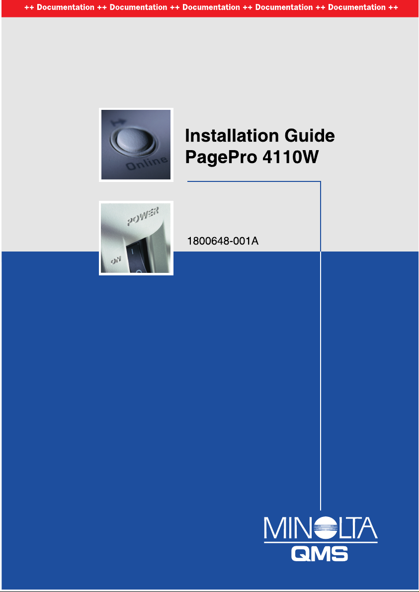
CDRH regulations
On 2 August 1976 the Center for Devices an d Radiol o gical Health
(CDRH), part of the US Food and Drug Administration, introduced
specifications f or all product s tha t operate wit h la se r bea ms. Products
which are to be sold or used in the USA must comply with these statutory
requirements without exce pt ion. The safety lab el s hown confirms
compliance with the CDRH regulations. This label must be attached to all
products sol d o r used in the USA.
Laser safety label
1-6
DANGER
Use the printer o nly a s describ e d i n this m anual!
Using the con trol s, ad j usti ng the p rinter or performin g pro cedu res other
than specified in this manua l m ay result in exposure to hazardous
radiation.
Ü Use th e printer onl y a cco rd i ng to the instruction s contained in this
guide and in th e Online U ser’s Manual.
Page 13
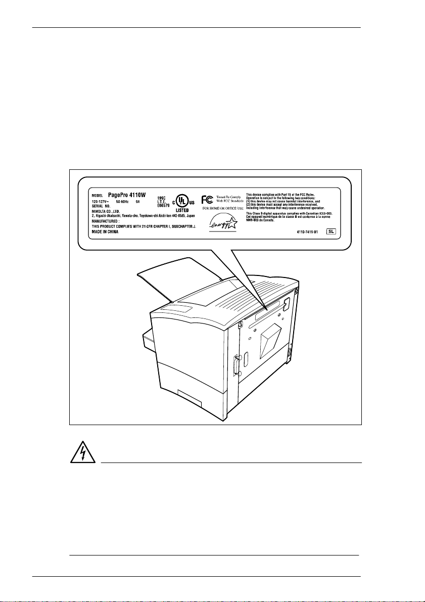
Introduction
Laser caution label
1
CAUTION
Dangerous laser radiation!
This is a semiconductor laser . T he m aximum po w e r of the laser diode is
5 mW and the wavelength is 770–810 nm.
Ü Use the printer onl y a c co rding to the instruct ion s contai ned in this
Guide and in the Online User’s Manual.
Ozone emission
Small quantities of ozone esc ape during the pri n t i ng process. These
quantities do not represent a health hazard. In spite of this, you should
take care that the area in which the machine is located has adequate
ventilation, especially when you are printing large quantities of materials
or when the machine is b eing u s ed continuou sly over a long period of
time.
1-7
Page 14

1
1.3 CE symbol (Declaration of Conformity)
We hereby declare that we are res pons i b le for ensuring that the printer
and the options to which this declaration relates comply with the
specifications given below. This declaration shall only apply to the area of
the European Union (EU).
Product Type Laser Beam Printer
Product Name PagePro 4110W
Options • Paper feed tray 2
Standard Safety*2 • EN60950/1992 with Amendments 1, 2, 3, 4 and 11
EMC*1 • EN55022 (Class B)/1998
EC
Directive
* 1: EMC performance: This product was designed for operation in a typical office environment
2: First year of labelling according to EC-directive 73/23/EEC and 93/68/EEC: 2000
Safety 73/23/EEC
EMC 89/336/EEC and 93/68/EEC
This unit mu st be operate d wi th a shie lde d interface cable and a shielded
network cable. T he use of no n-s h ie l d ed c a ble can result in radio
interference and is forbidden according to EC Regulation 89/336/EEC.
• Paper feed tray 3
• Duplex unit
• Expansion memory (Maximum 64MB)
• Network interfa ce card
Safety of information technology equipment, including
electrical business equipment
• EN60825-1/1994 with Amendment 11
Radiation safety of laser products, equipment classification,
requirements and User’s guide
Limits and method for measurement of radio disturbance
characteristic of information technology equipment (ITE)
• EN55024/1998
Information technology equipment – immunity
characteristics – Limits and methods of measurement
• EN61000-3-2/1995
Limits for harmoni c current emissions
• EN61000-3-3/1995
EMC, Part 3: Limits Section 3: Limitation of voltage
fluctuations and flicker in low voltage supply systems for
equipment with rated current ≤ 16A.
• IEC 61000-4-2/1995 Electrostatic discharge immunity test
• IEC 61000-4-3/1995 Radiated, electromagnetic field
immunity test
• IEC 61000-4-4/ 199 5 Electr ical fa st tr ansi e nt/b ur st immunity
test
• IEC 61000-4-5/1995 Surge immunity test
• IEC 61000-4-6/1996 Immunity to conducted disturbance,
inducted by ra dio-frequency fields
• IEC 61000-4-8/1993 Power-frequency magnetic field
immunity test
• IEC 61000-4-11 Voltage dips, short interruptions and voltage
variations immunity test
Introduction
1-8
Page 15

Introduction
1.4 User instructions
FCC Part 15 - Radio Fre q u e n cy De vices Warning (for users in the USA)
FCC: Declaration of Conformity
Product type Laser Beam P rinter
Product name PagePro 4110W
Options Paper feed tray 2
This device complie s with Part 15 o f the FCC Rules.
Operation is subject to the following conditions:
1. this device may not cause harmful interference, and
2. this device must accept any interference received, including interference
that may cause undesired operation.
This equipment has bee n tested and foun d to c om ply with the limits for a
Class B digital devi c e, pursuant to Part 15 of the FCC Rules. These limits
are designed to provide reas onabl e protect io n agai nst harmful
interference in a residen t ia l installa tion. This equipment g en erates, uses
and can radiate radio fre q u ency energy and, if not installed and used in
accordance with the instructions, may cause harmful interference to radio
communications. However, there is no guarantee that interference will not
occur in a particular install ation.
If this equipment does cause harmful interference to radio or television
reception, which can be determined by turning the equipment off and on,
the user is encouraged to try to co r rec t the interference by one or more of
the following measures:
l Reorient or relocate the receiving antenna.
l Increase t h e separation b etw een the equipment and the receiver.
l Connect the equipment into an outlet on a circuit different from that to
which the rec eiv er is connected.
l Consult the dealer or an experienced r ad io /TV tec hni cian for help.
Paper feed tray 3
Duplex unit
Expansion memory (Maximum 64MB)
Network interface car d
1
1-9
Page 16

1
Introduction
This devic e mu st be used wit h a shie ld e d inter f ace c ab le and shielded
network (10BaseT/100baseTX)cable. The use of non-shielded cables is
likely to result in interference with radio communications and is prohibited
under FCC rules.
The design and production o f th is unit confor m to FCC regulations, and
any changes or modifications must be regi st e r ed wi t h the FCC and are
subject to F C C contro l . Any changes made by the purchaser or user
without first contacting the manufacturer w i l l be subject to penalty under
FCC regulations.
Interference-causing Equipment Standard (ICES-003 ISSUE 3) Warning (for users in Canada)
This Class B di gi tal a p par a tus c o m pli e s wit h Can adian standard
ICES-003.
Cet appareil numérique de la classe B est conforme à la norme NMB-003
du Canada.
Ozone emission
Small quantities of ozone esc ape during the pri n t ing process. These
quantities do not represent a health hazard. In spite of this, you should
take care that the area in which the machine is located has adequate
ventilation, especially when you are printing large quantities of materials
or whether the machine is being used continuously over a long period of
time.
1-10
Page 17
Unpacking and setting up
2 Unpacking and setting up
2.1 Unpacking the laser printer
CAUTION
Danger to children from packaging materials made of plastic
Ü After unpacking the printer, keep the packaging materials out of reach
of children.
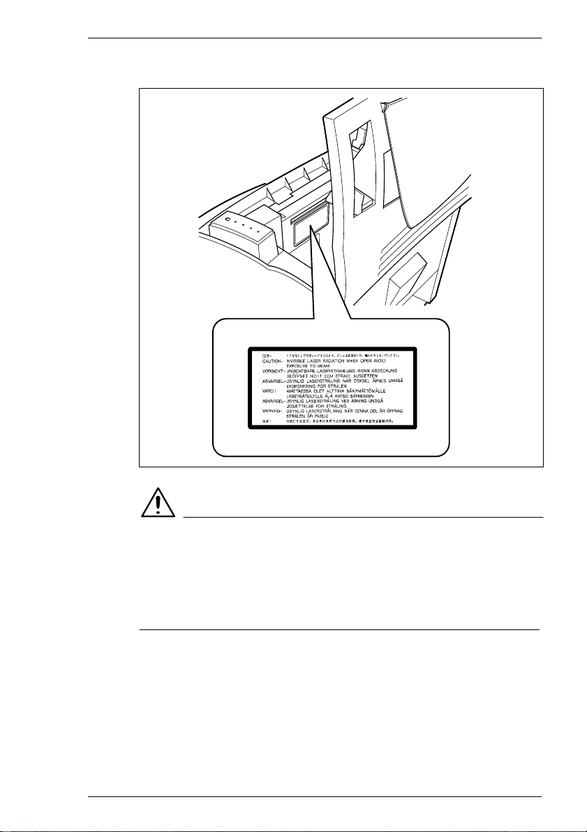
Remove the printer parts and
1
accessories from the box.
m Paper output tray
m Printer
m Installation Guide
m Software and
Docu ment at ion CD -R O
m Power cable
m Paper feed tray
Interface cables are not
included in the shipment. If you
need interface cables, contact
your local vendor or computer
store
2
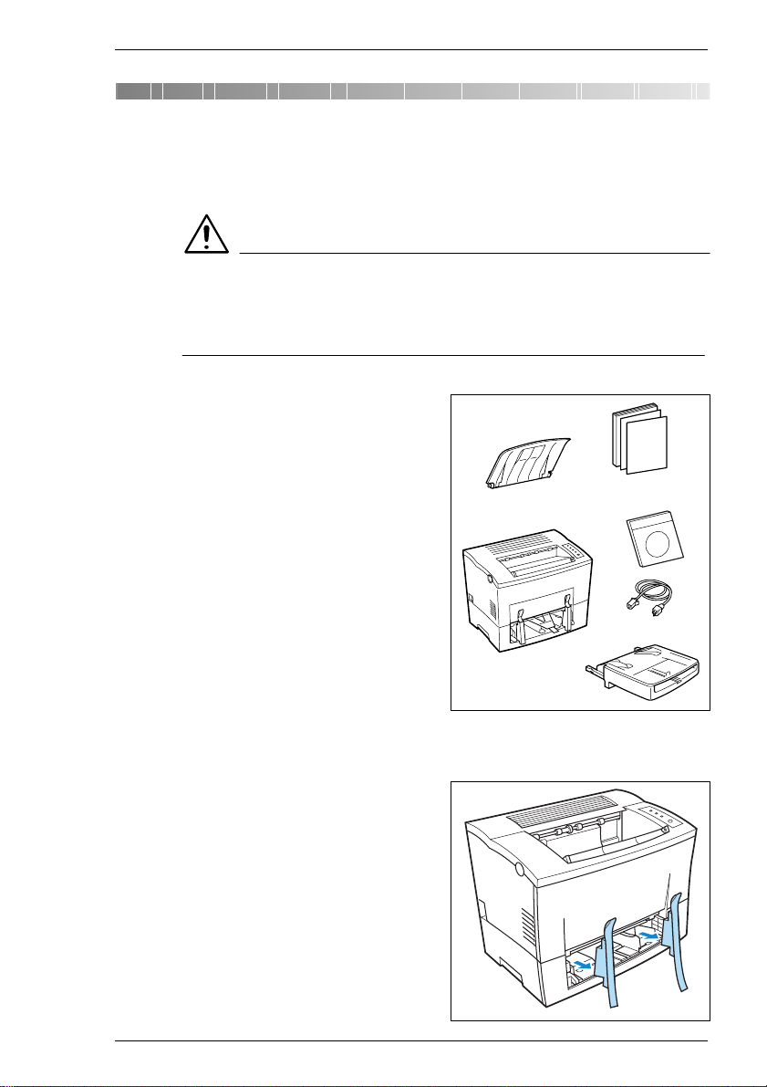
Remove the packaging material
2
from the printer.
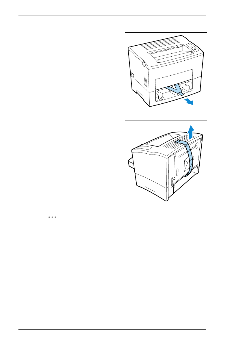
Remove the t rans port retaine rs
3
from the printer.
2-1
Page 18
2
Pull the pl ast ic stri p out of the
4
printer.
Remove the plastic strip from
5
the rear of the printer.
Unpacking and se tting up
2-2
.
Why save the packaging materials?
If you need to move the printer, you can use the packaging again. In
this way y ou can be certain that your printer is correctly packed.
Page 19
Unpacking and setting up
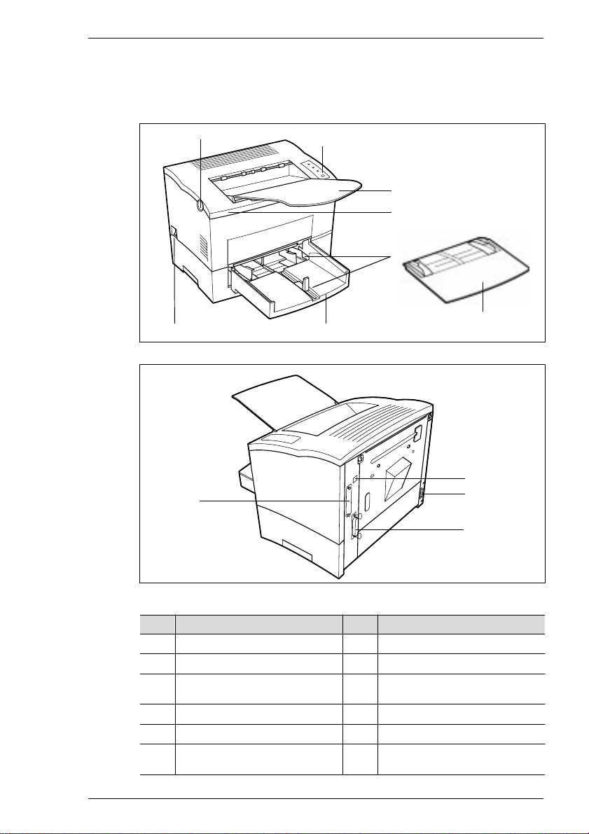
2.2 Overview of printer
External printer parts
2
12
1
2
3
4
5
8
67
9
10
11
No. Description No. Description
1 Release button for top cover 7 Power Switch (ON/OFF)
2 Control panel 8 Cover for paper feed tray 1
3 Paper output tray
(face down)
4 Top Cover 10 Socket for power cable
5 Paper guides 11 Parallel port
6 Paper feed tray 1
(multipurpose tray)
9 USB port
12 NIC option port
2-3
Page 20
2
Unpacking and se tting up
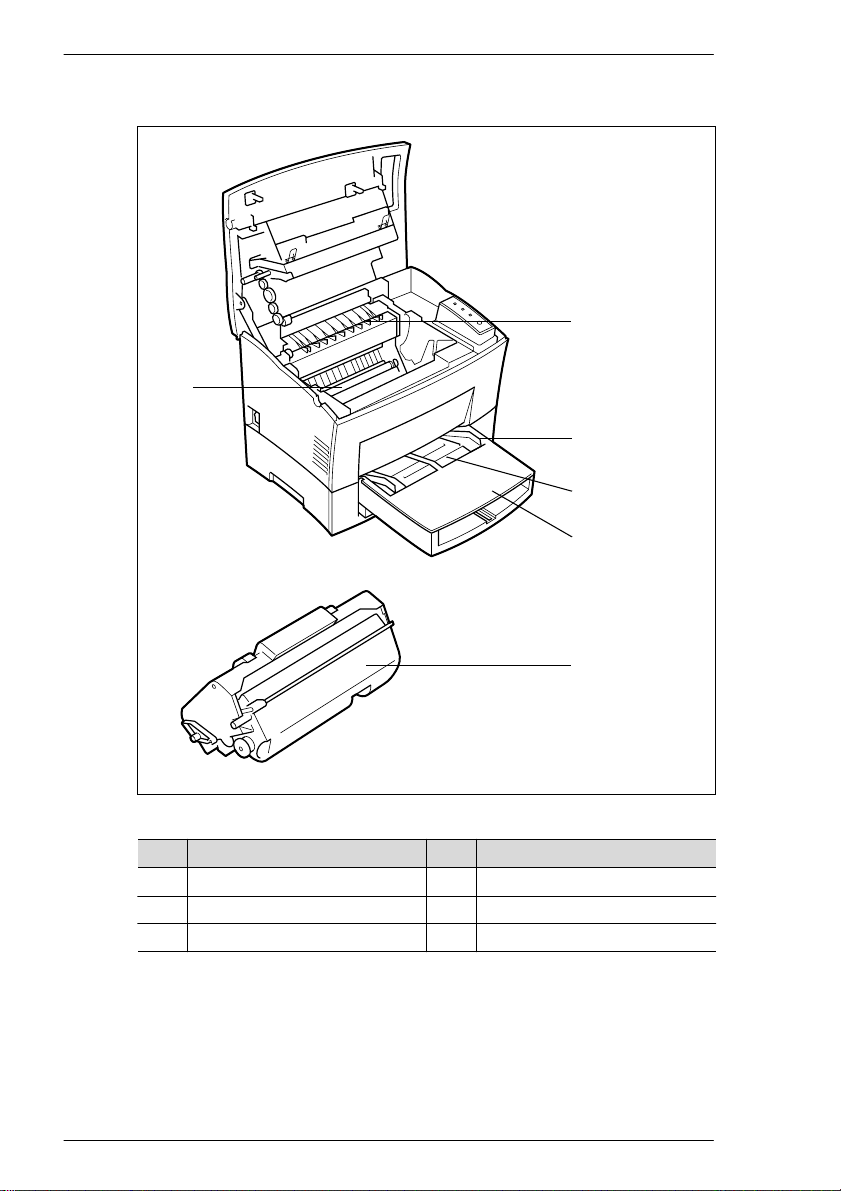
Internal print er part s
1
5
2
3
4
2-4
6
No. Des cription No. Description
1 Fusing unit 4 Cover for paper feed tray 1
2 Paper guide 5 Image transfer roller
3 Manual paper feed unit 6 Imaging cartrid ge
Page 21

Unpacking and setting up
Optional printer pa rt s
2
1
2
No. Description No. Description
1 Paper feed tray 2
(500-sh ee t cassette )
2 Paper feed tray 3
(500-sh ee t cassette )
3 Duplex Unit
4 Network interface card
3
4
2-5
Page 22

2
Unpacking and se tting up
Printer control panel
1
2
3
4
5
The control panel has four indicators and one button.
No. Description No. Description
1 Fault (orange) 4 Ready (green)
2 Toner empty (orange) 5 Control button
3 Paper empty (orange)
2-6
Please refe r to the On lin e U se r’s Man ual f or de tailed informat ion on the
control panel.
Page 23

Unpacking and setting up
2.3 Installing your laser printer
Place of installation
The printer should be set up in a pla ce which is
l dry and free from dust
l on a stable surface
l well ventilated
l away from highly flammable i te ms ( for example, curtains)
l away from obje cts which might obstruct the printer’s ventilation slits
l near to an easily accessib l e po wer socket
The printer must be positi o ne d in a way that it ca nno t be adversely
affected by the following:
l splashing liquids
l organic gases (for example, ammonia)
l direct sunlight
l severe temperature fluctuations
l exhaust-air from heating, ventilation or air-conditioning systems
Storage of co nsum ab les and accessories
Printing consumables and accessories should be kept:
l sealed in their origi n al p ac k agings,
l protected against direct sunlight or heat,
l protected against fluorescent light,
l in a cool, dry and dust-free place,
l out of the reach of children.
2
CAUTION
Toner poses a health hazard!
Toner may be harmful if inhaled.
Ü If you inhale toner, consult a doctor immediately.
Ü If you get toner on your hands, wash them immediately with cold water
and soap.
2-7
Page 24

2
Unpacking and se tting up
Ambient conditions
The optimum ambient conditions for your printer are:
l Temperatures from 50°F to 95°F / 10°C to 35°C
(maximum variation of 18°F / 10°C per hour)
l Relative humidity of 15% to 85%
(maximum variation of 2 0% per hour)
Space required
Make certain that there is enough space available around the printer (see
illustration). This will facilitate operation, reloading paper and toner, and
maintenance of the printer.
Space required for the standa r d model printer
H
2-8
D
A
No. Dimension No. Dimension
A 40-1/2 in. / 1030 mm E 23-1/2 in. / 600 mm
B 33 in. / 840 mm F 11-3/4 in. / 300 mm
C 24-3/4 in. / 630 mm G 4 in. / 100 mm
D 6 in. / 150 mm H 11-3/4 in. / 300 mm
E
F
C
G
B
Page 25

Unpacking and setting up
Space require d for the prin t er w h e n equ i p p ed w ith options
2
H
D
A
No. Dimension No. Dimension
A 40-1/ 2in . /1 030mm
46-1/2 in. *
B 33in./840mm F 11-3/4in./300mm
C29-1/2in./750mm
34-1/4 in *
D 6in./150mm
11-3/4 in *
* 1: when equipped with a duplex unit
2: when equipped with a third paper cassette unit
1
/ 1180 mm *
2
/ 870 mm *
1
/ 300 mm *
E
F
1
2
1
E 23-1/2in. / 60 0mm
G4in./100mm
H 11-3/4 in. / 30 0mm
B
C
G
2-9
Page 26

2
2.4 Please note the following points:
What should I watch o ut fo r when loa d i n g paper?
To avoid paper misfeeds in the laser printer, please obse r ve the following
points:
l Do not use any paper with the follow i ng f eat ures:
m Paper that has a lread y been used in a thermal or ink-jet printer.
m Paper that is t oo t hin or too thick.
m Folded or wavy paper.
m Paper having binding h o l es o r perforations.
m Paper with a surface that is too smooth, too rough or irregular.
m Specially coated paper such as carbon paper or paper with an
adhesive surface.
m Paper that is n ot cu t at right angles.
m Paper that is h eld tog e t he r by glue, adhesive or clips.
m Paper with labels that detach easily.
m Wa rped or curled-up pos tcards.
l Please note that the stack of paper in the paper tray should not exceed
the “max.” mark.
.
Note
When paper is loaded, the orientation is based on the format marks in
the paper source units.
Unpacking and se tting up
2-10
What should I watch o ut fo r when loa d i n g envelopes?
To avoid env elo pe misfeeds in the laser printe r, p l e as e observe the
following points:
l Do not u s e self-adhes ive envelo pes or those with a tear-of f strip,
closures or a window.
l Place the envelopes i n the tray long edge first.
l Place the envelopes i n t he t ray with the fl a p down so that the upper
surface of the envelopes is lying against the side of the tray with the
feed roller.
l Load envelopes of format B5 with the flap facing down and pointing to
the rear of the tray.
l Make certa in tha t the flaps are neatly folded back.
Page 27

Unpacking and setting up
.
Test the envelopes before buying large quantities!
Some typ es of envelopes cr ease e asi l y w hen th ey are run through a
printer. Te s t a type of envelope before purchasing large quantities.
Which sizes of paper can I use?
This printer is designed for use with the sizes of paper listed below.
Paper size
Standard sizes
A4
210 × 2 97mm
A5
148 × 2 10mm
JIS B5
18 2 × 257mm
Letter
8-1/2 in. × 11 in.
Legal
8-1/2 in. x 14 in.
Executive
7-1/2 in x 10-1/2 in.
Envelopes, postcard and custom sizes
Envelope DL
110 × 220mm
Envelope C5
162 × 250mm
Envelope B5
176 × 250mm
Envelope COM10
4-1/8 in. x 9-1/2 in.
Envelope Monarch
3-7/8 in. x 7-1/2 in.
J-Post (Postcard)
4 in. x 5-3/4 in.
Custom Size
3-3/8 in. to 8-1/2 in. × 3-1/2 in
to 14 in.
86 to 216mm × 9 0 t o356mm
Paper source
Tray 1 Tray 2/3
(option)
Yes Yes Yes
Yes No Yes
Yes Yes Yes
Yes Yes Yes
Yes Yes Yes
Yes Yes Yes
Yes No Yes
Yes No Yes
Yes No Yes
Yes No Yes
Yes No Yes
Yes No Yes
Yes No Yes
Manual paper
feed unit
2
2-11
Page 28

2
Unpacking and se tting up
What types of paper ca n I use?
This printer is d e signed for use with the types of paper listed below.
Paper source
Paper media
standard media:
Plain paper
weight: 16 to 24 lbs. / 60 to 90g/m
Recycled paper
weight: 16 to 24 lbs. / 60 to 90g/m
special media:
Transparent film Yes No Yes
Labels Yes No Yes
Letterhead Y es No Yes
Envelopes Yes No Yes
Postcard s Yes No Yes
Card or thick paper
24 to 43-1/4 lbs. / 9 0 to 163g/m
Tray 1 Tray 2/3
Yes Yes Yes
2
Yes Yes Yes
2
Yes No Yes
2
(option)
Manual paper
feed unit
.
2-12
Note
Special media is not supported for duplex pr i nting.
Page 29

Unpacking and setting up
2.5 Setting up your laser printer
Fitting the paper out pu t t r a y and paper feed tray 1
Attach the paper output tray to the
1
printer as shown.
Slide the lowe r part of the paper
2
feed tray into the printer.
2
Place the cover on top of paper feed
3
tray 1.
2-13
Page 30

2
Unpacking and se tting up
Loading paper into paper feed tray 1
Paper feed tray 1 has a capacity of 25 0 sheets of plain papier.
Remove the cover of paper feed
1
tray 1.
Using a large paper format?
?
Ü Then extend the paper support.
Place the paper between the paper
2
guides. Slide the guid es up to the
stack of paper.
How many sheets may I place
?
in the c a ssette?
Ü The stac k of paper should not
exceed th e “ma x.”m ark.
2-14
Place the cover on top of paper feed
3
tray 1.
Page 31

Unpacking and setting up
Connecting the power cable
Only use the powe r cab le sup pl i ed with the printer.
The laser printer req uir e s a power supply with minimal voltage and
frequency fluct uation. If n ece s sar y, ask an elec trician for advice.
4 Power supply: 120-127 V at 50-60 Hz / 220-240 V at 50-60 Hz
4 Vo lt a ge fluctuation: 1 2 0V -10%, 127 V +6% / 220-240 V ±10%
4 Frequency fluctu ation: Within 3 Hz
Make cert a in that the printer's
1
power switch is in the “0” (OFF)
position.
Insert the plug on the end of the
2
power cable (supplied) into the
power socket of the printer.
2
Insert the other end of the power cable into a power socket.
3
CAUTION
Using the wr o n g power c ab l e may cause a sh ort -circuit!
Using power cables of inadequate cross-s ection can lead to overheating
of the cable.
Ü Only use an extension cable which has a higher rating than the current
consumption of t he printer.
Ü Only use cables with a ground connection.
Ü Always ob ser ve the relevant loc a l regula tions regarding the
connection of electrical equipment to the ma i n power.
2-15
Page 32

2
Unpacking and se tting up
Switching the printer on
CAUTION
Improper handling may result in damage to the printer!
Ü Never switch off the printer while a print job is in progress, the printer
is receiving data from the computer (flashing “Ready” indicator on the
control panel) or the printer is being reset.
Switch the p owe r switch to “I”(ON).
1
2-16
The printer is rea d y for u se a fter approxi ma t e l y 23 seconds.
.
Saving energ y makes sense!
After the printer has not received a print command for approximately
15 minutes, it automatically switches to POWER SAVE mode. If the
printer receives a new print job while it is in Power Save mode, or if the
top cover is opened, or if the control button is p re ssed, the printer
automatically starts its warm-up phase.
Page 33

Unpacking and setting up
Printing a co n figu ration page
Print a configuration page in order to make sure that the printer is
functioning properly.
Make sure that correct media is placed in paper feed tray 1.
1
Hold down the [CONTRO L B U T TON] for more than 15 seconds until
2
the “Toner empty ” a n d “Ready” indic a to r s flash as shown below.
2
After the control button i s re lease d , the Config urat io n Page is printed.
.
Be well prepa red for technical queries.
Please have a cu rre nt configuration page available when calling for
technical assistance. Ma ke a note of the Se rial N o. of your printer on
the configuration page, see page 1-6 (laser safety label).
2-17
Page 34

2
Unpacking and se tting up
Connecting t he pr i n t e r to a com p ute r (parallel port)
Switch off the printer and the
1
computer.
Connect one end of the
2
interface ca bl e to the parallel
port of your computer.
Connect the other end of the
3
interface ca bl e to the parallel
port of the printer.
Secure th e connector by
4
means of the clips on the
socket.
For the technical s pecifications of the cable, see page 6-5.
CAUTION
Using the wron g t y p e o f ca ble may r esul t in damage to the
equipment!
Using the wrong t ype of cable may damage th e socket on the printer.
Ü Only use an IEEE 1284 type B shielded interface cable for connecting
the printer to your computer.
Ü MINOLTA-QMS does not warrant the use of any particular cable. The
user assumes all responsibilit y a s to the qua li ty an d performance of
the ca b l e .
2-18
Proceed wit h cha pt e r 3, “Installing th e Pri nt er driver.”
5
Page 35

Unpacking and setting up
Connecting t he printer to a com pu t er (USB port)
When connecting the PagePro 4110W printer to your computer with a
USB cable, you m us t first i ns ta l l the PagePro 41 10 W US B device driver
before you install t he pr inter d river.
.
Note
In the fol low ing procedures it i s a s sumed that you are installing the
PagePro 4110W USB device driver on your computer for the first time.
This printer can be connected with a USB cable only if your computer is
running Win d ows 98, Windows Me, or Windows 2000.
Installin g the US B dev ice driver for Windows 98 or Windows Me
.
Note
The screen i m ages s h ow n in th is sec ti on a r e examples of the
installation fo r Windows 9 8. Th e scr een images m ay differ slightly for
Windows Me.
Switch on your computer and st art Windows 98 or Windows Me.
1
2
Switch on the p rinter. Do not yet connect the USB cable.
2
Check that Windows 98 or Windows Me has finished loading and that
3
the pr i n ter is ready.
Insert the Software and Documentation CD-ROM supplied with your
4
printer into your computer’s CD-ROM drive.
When the CD-ROM installation sc reen appears, close it.
5
Connect the printer to the
6
computer with the USB cable.
2-19
Page 36

2
Unpacking and se tting up
The Add New H a r dware Wizard dialogue will display.
7
Install the USB de v ice driver from the S oftware and Documentation
8
CD-ROM by following the ins tr uct i ons on the screen. During the
installation specify the location of the USB Driver on the Software and
Documentation CD-ROM as follows:
m For Wi ndow s 98: “Dri vers\Pp4110W\Win98\Gb\ Gdi\D rv\usb”
m For Wi ndows Me : “Driver s\Pp41 10W\ W in Me\Gb \Gdi\D rv\usb”
2-20
Need more infor ma tion?
?
Ü For detailed inform ation on t h e install ati on setti ngs p lease refer to
the Online User’s Manual.
Page 37

Unpacking and setting up
After the USB device driver i s installed, a “greetings” screen appears.
9
Although you may proc eed with this screen now to install the printer
driver, we recomme nd t h a t you exit this screen and install the printer
driver later using the CD-ROM i nstaller.
Check that “Minolta/QMS PagePro 4110W” appears bel ow U niversal
10
serial bus controller on the Device Manager tab of the System
Properties dialogue.
2
How do I open the System Properties Dialogue?
?
Ü Click with the right -hand mouse button on the [MY COMP UTER ]
icon on the desktop, and then click [PROPERTIES] in the shortcut
menu that appears.
Proceed with chapter 3, “Insta llin g t he Printer Driver.”
11
2-21
Page 38

2
Unpacking and se tting up
Installing the USB Device Driver for Windows 2000
Switch on your computer and start Windows 2000.
1
Switch on the p rinter. Do not yet connec t the USB cable.
2
Check that Windows 2000 has finished load i ng a nd that the printer is
3
ready.
Insert the Software and Docu m en tat i o n CD - ROM supplied with your
4
printer into your computer’s CD-ROM drive.
When the CD-ROM installation screen appears, close it.
5
Connect the printer to th e computer
6
with the USB cable.
2-22
The Found New H a rdware Wizard dialogue w i ll display.
7
Page 39

Unpacking and setting up
Install the USB device by following the instructions on the screen.
8
During the ins tall a tion s pe cify the lo cati o n of the USB Driver on the
Software and Docume ntat ion CD-ROM as follows:
“Drivers\Pp 4110W\Win2000\ Gb\G di\Drv\usb.”
Need more infor ma tion?
?
Ü For detailed inform ation on the install ati on s ettin gs p lease refer to
the Online User’s Manual.
When the fo llo wi ng di alo gu e a ppears, check the “Disable the device.
9
The Add/Rem ove Hard war e Wizard in the Control Panel can be used
complete the driv er i nstallation.” box, and then click [FINI SH].
2
Open the “Device Manager.” Then double-click the “USB Printing
10
Support” below “Universal Serial Bus controllers.”
2-23
Page 40

2
Unpacking and se tting up
How do I open the Device Manager?
?
Ü Click with the rig ht -hand mouse button on the [MY CO MPUTER]
icon on the desktop, and then click [PROPERTIES] to open the
“System Properties” dialogue.
Ü Click the “Device Manager” button on the “Hardware” tab of the
“System Properties” dialogue.
Click the [UPDATE DRIVER] button on the “Driver” tab.
11
The “Upgrade Dev ice Driver Wizard” appears.
Update the D evi c e Drive r with the USB Driv er from t he So ftware and
12
Documentation CD-ROM by following the instruct ions on the screen.
During the ins tall a tion sp ecify t h e locati on o f t he U SB Driver on the
Software and Documentation CD-ROM as follows:
“Drivers\Pp4110W\Win2000\ Gb\Gdi\Drv\usb“
You need more information?
?
Ü For detailed inform ation on t h e install ati on setti ngs p lease refer to
the Online User’s Manual.
After the USB devi ce drive r is installed, a “greetings” screen appears.
13
Although you may proceed with this screen to install the printer driver,
we recommend to exit this and later proceed installing the printer
driver u s in g the CD -ROM instal le r.
2-24
Restart the computer.
14
Page 41

Unpacking and setting up
After the Computer is restarted, open the Device Manager and check
15
that “Minolta/QMS PagePro 4110W” appears be l ow “ Uni ve r sal Serial
Bus controllers.”
Proceed with chapter 3, “Insta llin g t he Printer Driver.”
16
2
2-25
Page 42

2
Unpacking and se tting up
2-26
Page 43

Installing the printer driver
3 Installing the printer driver
3.1 System requireme nts
The following system require me n t s will en sure that your printer runs
without problems:
l Personal Computer: IBM-compatible PC with at least a Pentium
150 MHz CPU
l Operating System: Microsoft Windows95, Windo ws98,
Windows Me, Windows 2000,
or Windows NT4.0
l Memory: Windows 95/98/NT4.0: At least 16 MB of RAM
Windows Me: At least 32 MB of RAM
Windows 2000: At least 64 MB of RA
l Free disk space: Approximately 100 MB of available memory
l CD-ROM drive
l I/O interface: IEEE 1284/ECP/EPP/Bi-Di/compatible
USB (Available onl y when using Windows 98,
Windows Me, o r W i ndow s 2000)
3
3.2 Notes on installing the printer driver
The installation program is designed so that even p eop le not accustomed
to working with computers can easily accomplish it. You will be guided
step by step through the installation process. All you need to do is follow
the installation program.
Before you begin the in s talla t i on, you should obser ve the following points:
l What operating system is running on your computer?
l What is the letter of your CD-ROM drive (D, E, etc.)?
l Which optional accessories are fitted to your printer?
l Is your printer a local printer or a network printer?
m Local printer:
When the printer is connect ed directly to your computer via a
parallel inter f ace cabl e or USB in terface cable.
m Network printer (option):
When the printer is integrated into a computer network.
3-1
Page 44

3
Installing the printer driver
General printer driver information
The printer driver is supplied on a CD-ROM a lo n g with the printer. If your
computer has no CD-ROM drive, you may download the printer driver
from the Internet.
You may find the latest version of the printer driver under the address
http://www.minolta-qms.com.
Informa tion on ins tallatio n using Plug-and-Play or Add Printer Wizard
We recommend to use the Software and Documentation CD-ROM´s
installer. If y o u instal l the prin ter d river usi ng Plug-an d -Play or the Add
Printer Wizard, you shou ld not e these po ints:
l The Driver directory on t h e Soft w are and Documentat ion CD-ROM
must be specified.
l The Status Displ a y and Driv er Help will not be installed.
l The auxiliary program for deinstallation will not be installed. To use this
auxiliary progr a m, start the file “zuninst.exe” on t he Software and
Documentation CD-ROM that is supplied with your printer.
3-2
Informa tion on insta lling a netw or k printer
.
Local printer or network printer?
The printer can be equipped with an optional network card if required.
Contact your local v endor.
You can insta ll the printer a s a local printer or a s a network printer. You
should make note of the following points when installing as a network
printer:
l We recommend consulting your network administrator and referring to
the Network Interf ace Card User´s Manual on the Software and
Documentation CD ROM.
l Server Install is not available under t he followin g circumstances:
m A Windows NT4.0 server and a Windows 2000 client
m A Windows 2000 server and a Windows NT4.0 client
Page 45

Installing the printer driver
3.3 Installing the printer driver using the Installer
Make certain th at th e printer is connected to you r com pu t er locally or
1
through a network.
Switch on the p rinter.
2
Switch on the c om p u t er an d start W indows95 , Windows98,
3
Windows Me, Wind o ws2000, or Windows NT4.0.
What do I do when the Update Device Driver Wizard or Add
?
new Hardware Wizard dialog appears:
Ü Click “Cancel” to close the dialog.
Place the PagePro 4110W Software and Docu mentation CD-ROM
4
into the CD-ROM dr ive o f your co mputer.
The installation pr ogram start s automa tically.
What if the installation program does not start automatically?
?
Ü Start Windows Explorer and open the directory of the CD-ROM.
Ü Double-click on “MINOLTA-QMS.EXE” to start the insta llation
program.
3
In the next dialo g window, choose the language for the installation
5
procedure.
3-3
Page 46

3
Installing the printer driver
Follow the instru ction s on the screen to comple t e the installation.
6
During the installat i on a scree n will appea r w h ere you may select the
7
port. When you have installed the PagePro 4110W USB device driver,
select [U SB/P AGEPR O 4110 ]. Fo r the parallel port, select [LPT 1].
After the printer driver has been installed, the “Minolta/QMS Printer
Utilities” Program Group appears.
3-4
You may now access the “Minolta_QMS Printer Utilities” Program Group
via the Window s Start menu.
Page 47

Installing the printer driver
3.4 Uninstalling the Printer Driver
Click on the “Minolta_QMS Printer Util ities” P rogra m Group.
1
Click on “Uninstall.”
2
The deinstallation program starts automatically.
Follow the subsequent instructions.
3
The deinstallation of the printer d riv er i s su c c ess ful l y com pleted once
the Windows operating system has been restarted.
.
Note
The USB dev i ce driver is uninstalled automatical ly with the printer
driver.
3
3-5
Page 48

3
Installing the printer driver
3-6
Page 49

Starting the Online User’s Manual
4 Starting the Online User’s Manual
4.1 Notes on the Online User’s Manual
The PagePro 4110W is supplied with a n Online User’s Manual. This
Online User’s Manual contain s ext ens ive information on the following
topics, among others:
l Working with the printer driver.
l Working wi t h the printer’s sta t us display.
l Installing op tional accessories.
l Caring for and maintaining yo ur p rinter
l Identifying a nd recti fying problems.
You need the Adobe Acrobat Reader software to access the Online User’s
Manual.
.
Install Adobe Acrobat Reader
If you do not already have Adobe Acrobat Reader installed on your
computer, simply start the Online User’s Manual. At a certain point you
will be asked if y o u want t o insta l l Ad obe Acr obat Reader (English
version). If you wish to install another language version of Adobe
Acrobat Reader t h an English , cance l this dia lo gu e and install the
desired lang ua ge v er s i on via the “ E xt ra So ftware” button.
4
The Online User’s Manual is not automatically installed on the hard disk
of your co mputer when i nst alling the printer driver.
Therefore, t o sta rt the Onli n e Us e r’ s Manual you have to insert the
PagePro 4110W Software and Documentation CD-ROM into the
CD-ROM drive of your computer and start the Online User’s Manual from
there.
You can al s o copy the Onl ine Use r’ s Manual to the hard disk of your
computer. The PDF file of the Online User’s Manual can be found in the
“Manual“ dire ctor y o f the Pag ePro 4110W Software and Docu mentation
CD-ROM.
4-1
Page 50

4
Starting the Online User’s Manual
4.2 Start the Online User’s Manual as follows:
Switch on the computer and start Windows 95, Windows98, Windows
1
Me, Windows 2000, or Windows NT4.0.
Place the PagePro 4110W Software and Documentation CD-RO
2
into the CD-RO M drive o f your c omputer.
The installation window op ens auto matically.
What if t he installat ion wi n d ow does not appear automatically?
?
Ü Start Windows Explore r and navigate t o the c ontents of the
CD-ROM.
Ü Double-click on “MINOLTA-QMS.EXE.”
The installation program “Welcome” window briefly appears on the
screen. It is replaced after a few seconds by the following
inst al la ti on w in do w.
4-2
Choose the language you prefer and then click on [NEXT].
3
Page 51

Starting the Online User’s Manual
In the following window click on [LOOK AT MANUAL].
4
If Adobe Acrobat Reader has already been installed on your computer,
the software is launched automatically to either view on-screen or print
a hard copy.
4
Adobe Acrobat Reader is not already installed on your computer?
?
You need Adobe Acrobat Reader in order to access the Online
User’s Manual.
Ü Install Adobe Acrobat Reader from the Software and
Documentation CD-R OM via the [EXTRA SOFTWARE] button.
4-3
Page 52

4
Starting the Online User’s Manual
4-4
Page 53

Troubleshooting
5 Troubleshooting
5.1 Clearing a Paper Misfeed
Outside the Printer
Remove the misfed sheet o f paper by pulling it in the direction indicated
by the arrow.
Face-d o w n tr a y
5
Tray 1
Manual feed tray
5-1
Page 54

5
Troubleshooting
Inside the Printer
Remove the misfed sheet of pape r by pulling it in the direction indicated
by the arrow.
CAUTION
The fusing un i t can become very hot!
Ü The fusing u nit inside the printer ca n bec ome very hot during
operation. Do not touch t he area to avo id injury.
Ü Do not tou c h the image tra nsf er roller.
5-2
Solving Print Quality Problems
l Remove the imaging cartridge and gently shake it a few times to
distribute remaining toner.
l Remove the ima ging cartridge and c heck it for damage. Replace the
imaging cartridge with a new one if necessary.
l Clean the inside of the printer.
For more details, refer to the “Troubleshooting” and “Maintenance”
sections of th e On lin e User’s Manual.
No Output
l Make sure that the printer is plugged in.
l Make sure that power is turned on.
l Make sure that y ou ar e using the correct type of interface cable
l Make sure that y our compu ter ’s com muni cat ion port settings are
correct.
For more details refer to the Online User’s Manual.
Page 55

Appendix
6 Appendix
6.1 Performance features
Hardware
In terms o f hardw are , the Pag e Pro 4110W offers you the following:
l 1200 x 1200 dpi
l Up to 18 ppm ( A4/Letter)
l High performance processor optimized for Windows
l Minolta Qui ckPage tec hn o logy for fast Windows printing
l Parall e l port
l USB port
l Upgrade with (optional) network card
l Upgrade with (optional) duplex unit
l Upgrade with (optional) paper feed trays (maximum 2)
l Upgrade with (optional) memory modules (DIMMs)
Operating systems
The PagePro 4 1 1 0W ca n be used w ith the following operating systems:
l Windows 95
l Windows 98
l Windows Me
l Windows 2000
l Windows NT4.0
6
6-1
Page 56

6
6.2 Technical specification
PagePro 4110W printer
Technical specification
Type Desktop laser printer
Print system Electrostatic dry powder imaging system
Exposure system Laser diode + polygon mirror scanning
Resolution 1200dpi x 1200dpi, 1200dpi × 600dpi, 600dpi × 600dpi
Printing speed
(single-sided)
Printing speed
(double-sided)
Time to 1st page
(single-sided)
Time to 1st page
(double-sided)
Warm-up time max. 23 sec.
Paper formats A4, A5, JIS B5, Letter, Legal, Executive, Invoice, J-Post,
Paper/Media •Plain paper (16 to 24 lbs. / 60 to 90g/m
Paper sources •Paper feed tray 1 (muiltipurpose tray)
Input capacities •Paper feed tray 1 (multipurpose tray): 250 sheets
Output capacity •Output tray (printed side down):250 sheets
Operating temperature 50°F to 95°F / 10°C to 35°C (fluctuations 18°F / 10°C per hour)
Humidity 15% to 85% (fluctuations max. 20% per hour)
Imaging cartridge life 9,000 pages A4 or Letter with a black-to-white ratio of max. 5%.
Voltage supply 120-127V / 220-240V at 50-60 Hz
Current consumption •Operation: max. 820 W
Amperage max. 7.0 A (120 V) / 3.8 A (220-240 V)
18 ppm (A4 or Letter)
8.9 ppm (A4 or Letter)
18 sec. (A4 or Letter)
28.5 sec. (A4 or Letter)
Commercial 10, Monarch, DL, C5 and B5 envelopes
•Recycled paper (16 to 24 lbs. / 60 to 90g/m
•OHP film (transparencies)
•Envelopes
•Card and thick paper (24 to 43-1/4 lbs. / 90 to 163g/m
•Letterhead
•Labels
•Postcards
•Manual feed unit
•Paper feed tray 2 (option)
•Paper feed tray 3 (option)
•Paper feed tray 2: 500 sheets
•Paper feed tray 3: 500 sheets
(The starter imaging cartridge supplied with the printer is
capable of producing approx. 5,000 pages A4 or Letter.)
•Stand-by: max. 60 W
•Power Save mode: max. 20W (120V) 11.9W (220V)
2
)
Appendix
2
)
2
)
6-2
Page 57

Appendix
Technical specification
Dimensions
(without optional paper
feed trays)
Weight Printer: Approximately 28-3/4 lbs. / 13 kg
Interfaces • Centronics parallel port IEEE 1284B/ ECP / EPP/Bi-Di/
CPU HD6437040 / 28MHz
RAM 2 MB (can be expande d to 66MB)
Options • Paper feed tray 2 (500 sheets)
Height: 13 in. / 331mm
Width: 17-5/32 in. / 436mm
Depth: 20 in. / 508mm
Imaging cartridge: Approximately 3-1/4 lbs. / 1.5 kg
Compatible
•USB
• Paper feed tray 3 (500 sheets)
• Duplex unit
• Network card
• Memory expans io n (DIMM)
500-sheet paper f e ed tray (option)
Technical specification
Paper cassette Standard cassette: Letter
Paper • Plain paper (16 to 24 lbs. / 60 to 90g/m
Paper feeding system One-way system (multi-feed tray)
Capacity max. 500 sheets (plain or recycled paper)
Dimensions Height:4-3/4 in. / 12 1mm
Weight approximately 10 lbs. / 4.5 kg
Options: A4, Legal, Executive
2
• Recycled paper (16 to 24 lbs. / 60 to 90g/m
Width: 17-1/4 in. / 438 mm
Depth: 13-3/4 in. / 350 mm
not including the cassette
)
2
)
6
6-3
Page 58

6
Duplex unit ( option)
Technical specification
Paper feeding system One-way system
Paper • Plain paper (16 to 24 lbs . / 60 to 90g/m
Operating temperature 50°F to 95°F / 10°C to 35°C
Humidity 15 to 85%
Dimensions Height:10-3/4 in. / 273 mm
Weight Approximately 5 lbs. / 2.3 kg
• Recycled paper (16 to 24 lbs . / 60 to 90g/m
Width: 12-3/4 in. / 324 mm
Depth: 6 in. / 152 mm
Network c ard (option)
Technical specification
Type Ethernet
Version • 10BaseT/100BaseTX
2
)
Appendix
2
)
6-4
Expansion memory module (option)
Technical specification
Capacity 32, 64 MB
Parity Non-parity
Access speed 10 ns or less (100 MHz)
No. of pins 100
Type of module SDRAM DIMM (Dual In-line Memory Module)*
* This printer supports 32 bit/100pin SDRAM DIMM which consists of 4 bit, 8 bit, or 16 bit
SDRAM chips, in JEDEC standard, such as:
H4143A(32MB), H3913(64MB)
Viking:
Golden RAM:
Melco (Buffalo):
Crucial Technology:
CT16M32S4P10(64MB)
Delkin D evi ces:
DM100-064Y3Q488-10D2P(64MB)
C4143A
PM-HP32M(32MB), C3913(64MB)
CT8M32S4P8(32MB), CT8M32S4P10(32MB), CT16M32S4P8(64MB),
DM100-032Y3Q488-10S1P(32MB), DM100-032Y3Q446-10D2P(32MB),
Page 59

Appendix
Parallel Int e rface a nd cable
Technical specification
Connections Printer: parallel 36-pin connection
Type of cable Shielded
Parallel cable IEEE 12 84, type B
Length of cable max. 10 feet / 3 meters
Computer: EIA 25-p in conne ction
Signal and ground pairs must be twisted
USB interface a nd cable
Technical specification
Connections Printer: Series B connection
Type of cable Shielded
Parallel cable IEEE 12 84, type B
Pin allocation 1: V
Length of cable max. 17 feet / 5 meters
Computer: Series A connection
Signal and ground pairs must be twisted
BUS
2: D+
3: D4: GND
Shell: Shield
6
6-5
Page 60

6
6.3 MINOLTA-QMS's concern for environmental protection
What does the En e rg y Star mean?
Appendix
Laser printers with the Ener gy Star
power consumption if not been used f or a c er tain amount of time. This
function can reduce your electrical costs by up to 60%.
This laser pri nt er fulfi ls the ene rg y efficiency cri te ria f or t h e Energy Star
of the EPA (USA Environmental Protection Agency).
®
feature switch into a state of low
®
6-6
Page 61

Appendix
6.4 Index
A
Adobe Acrobat Reader, installing ........................................................4-1
Ambient condition s
C
Cable specifications .............. .. .. .. .... .. .. .. .... .. .. .... .. .. .. .... .. .. .. .... ...............6-5
CDRH regulations
Configuration p age, printing out
Con sumables , stor ing
E
External printer parts .... .. .. ................ ................ .. ................ .................2-3
I
installation usi ng Pl ug-an d Play or Add Print er Wizard ........ ...... .... ..... 3-2
Interfac e connections
6
............. ...... ...... ...... ...... ...... ...... ...... ...... .................2-8
................................................................................1-6
.... .. .. .. .. .. .. .. .. .. .. .... .. .. .. .. .. .. .. .. ............ 2 -17
.... ...... .... ...... ...... .... ...... ...... .... ...... ...... ................2-7
.... .... .... ...... .... ...... .... ...... .... ...... .... ...... ................6-5
L
Laser cautio n label ........... .. .. .... .. .. .... .. .. .. .... .. .. .. .... .. .. .... .. .. .. .................1-7
Laser printer
connecting to computer
installing
settings
unpacking
Laser safety label
Loading paper
Paper feed tray 1
.......... .. ................ .. .. ................ .. .. ................ .. .. .................2-7
.................. .. .. .. ................ .. .. ................ .. .. .........................2-13
.................... .. .. ................ .. .. ................ .. .. .......................2-1
................................................................................1-6
....................................................................................2-10
............. .. .. ................ .. .. ...........................2-18
........ .. .. .. .. .. .... .. .. .. .. .. .. .. .. .. .. .... .. .. .. .. .. .. ...............2-14
N
Network card ................................ .......................................................6-4
6-7
Page 62

6
Appendix
O
Online manual
Installing A d obe Acrobat Reader
Notes on the online manual
Overview of print er
Optional printer parts
Printer control panel
..............................................................................2-3
.....................................................................2-5
......................................................................2-6
.......... .. .. .. .. .... .. .. .. .. .. .. .. .. .. .. .........4-1
........................ ........ ........ ........ ...........4-1
P
PagePro 41 10W printer, technical specification ............. .................... 6-2
Paper Misfeed
Paper output tray
Paper sizes, feasible
Paper specifications
Parallel print er por t
Performance fe atur es
Place of installation
Power cable, conne cting
Print Quality Problems
Printer accessories, storing
Printer driver
Installation
Notes on installation
Uninstalling the printer driver
Prin ti ng env e lop es
Printing the test page
.....................................................................................5-1
..............................................................................2-13
. .... .... .. .... .... .... .... .... .... .... .... .... .... .............2-11, 2-12
.......... .. .. .. .. .. .... .. .. .. .. .. .. .. .. .. .. .... .. .. .............2-11, 2-12
............................................................................2-18
.........................................................................6-1
.............................................................................2-7
...................................................................2-15
........................................................................5-2
.................................................................2-7
..... .. ................ .............................. ................ ................3-1
....... ...... ...... ...... ...... .... ...... ...... ...... .................3-1
.........................................................3-5
...... .......... .......... .......... ............ .......... ..................2-10
........................................................................2-17
6-8
S
Setting up output tray ........................................................................2-13
Setting up the lase r printer
Paper output tray
Printing the configur ation page
Space required
Starting the online manual
Storage of cons umab l e s and printer acc e ssories
Switching the printer on/off
System requirements
. .. .. .. .. .. .. .... .. .. .. .. .. .. .. .. .. .. .... .. .. .. .. .. .. .. .. .. ..............2-13
.................. ........ ...... ........ ............2-17
....................................................................................2-8
................ ........ ...... ........ ........ ........ ............4-2
............... .... .. .. ........ 2-7
...............................................................2-16
...... .... .. .... .. .... .. .. .... .. .... .. .... .. .... .. .... .. .. ................3-1
Page 63

Appendix
6
T
Techni ca l s pec ification
500-sheet paper feed tray
Dupl ex unitDuplex un i t
expansion memory module
Interface co nnections and cables
Network card
PagePro 4110W printer
USB Interface and cable
.......... ............................................ ............................6-4
...... .... .... .. .... .... .. .... .. .... .... .. .... .... ............6-3
.......... .... ...... .... ...... .... ...... .... ...... .... .............6-4
............................................................6-4
.... .. .. .. .. .. .. .. .. .. .. .... .. .. .. .. .. .. ..........6 -5
.................................. ...............................6-2
.......... .. .. .. .. .. .... .. .. .. .. .. .. .. .. .. .. .... .. .. ............6-5
U
Uninstalling the printer driver ...............................................................3-5
Unpacking the laser printer
USB Device Driver
USB Interface and cable
User instructions
................ ...... .... ...... .... .... ...... .... ...... .... .................2-19
..................................................................................1-9
..................................................................2-1
............................................ ..........................6-5
6-9
Page 64

6
Appendix
6-10
 Loading...