

Page 1

SERVICE MANUAL
MODEL
LT-203
Large Capacity Tray Unit
NOVEMBER 2002
CSM-LT203
Page 2

Page 3

LT-203
SERVICE MANUAL
Used On Model 7145
November 2002
Page 4

IMPORTANT NOTICE
Because of the possible hazards to an inexperienced
person servicing this equipment, as well as the risk of
damage to the equipment, Konica Business Technologies strongly recommends that all servicing be
performed by Konica-trained service technicians only.
Changes may have been made to this equipment to
improve its performance after this service manual was
printed. Accordingly, Konica Business Technologies,
Inc., makes no representations or warranties, either
expressed or implied, that the information contained
in this service manual is complete or accurate. It is
understood that the user of this manual must assume
all risks or personal injury and/or damage to the
equipment while servicing the equipment for which
this service manual is intended.
Corporate Publishing Department
© 2002, KONICA BUSINESS TECHNOLOGIES, INC.
All rights reserved.
Printed in U.S.A.
Page 5

CONTENTS
CONTENTS
SAFETY AND IMPORTANT WARNING ITEMS
Refer to the 7145 service manual on page . . . . . . . . . . . . . . . . . . . . . . . . . . . . . . . . . . . . . . . . . . . . . . . . S-1
I OUTLINE
1. LT-203 PRODUCT SPECIFICATIONS. . . . . . . . . . . . . . . . . . . . . . . . . . . . . . . . . . . . . . . . . . . . . . . . . 1-1
2. CENTER CROSS-SECTIONAL DIAGRAM . . . . . . . . . . . . . . . . . . . . . . . . . . . . . . . . . . . . . . . . . . . . . 1-2
3. DRIVE SYSTEM DIAGRAM . . . . . . . . . . . . . . . . . . . . . . . . . . . . . . . . . . . . . . . . . . . . . . . . . . . . . . . . . 1-3
3.1 Rear side drive . . . . . . . . . . . . . . . . . . . . . . . . . . . . . . . . . . . . . . . . . . . . . . . . . . . . . . . . . . . . . . . 1-3
3.2 Front side drive . . . . . . . . . . . . . . . . . . . . . . . . . . . . . . . . . . . . . . . . . . . . . . . . . . . . . . . . . . . . . . . 1-3
II UNIT EXPLANATION
1. PAPER FEED SECTION . . . . . . . . . . . . . . . . . . . . . . . . . . . . . . . . . . . . . . . . . . . . . . . . . . . . . . . . . . . 2-1
1.1 Composition. . . . . . . . . . . . . . . . . . . . . . . . . . . . . . . . . . . . . . . . . . . . . . . . . . . . . . . . . . . . . . . . . . 2-1
1.2 Operation. . . . . . . . . . . . . . . . . . . . . . . . . . . . . . . . . . . . . . . . . . . . . . . . . . . . . . . . . . . . . . . . . . . . 2-2
1.2.1 Tray up drive control . . . . . . . . . . . . . . . . . . . . . . . . . . . . . . . . . . . . . . . . . . . . . . . . . . . . . . 2-2
1.2.2 Paper feed control . . . . . . . . . . . . . . . . . . . . . . . . . . . . . . . . . . . . . . . . . . . . . . . . . . . . . . . . 2-2
1.2.3 Remaining paper detection control. . . . . . . . . . . . . . . . . . . . . . . . . . . . . . . . . . . . . . . . . . . . 2-3
III DISASSEMBLY/ASSEMBLY
1. PAPER FEED SECTION . . . . . . . . . . . . . . . . . . . . . . . . . . . . . . . . . . . . . . . . . . . . . . . . . . . . . . . . . . . 3-1
1.1 Removing the LT . . . . . . . . . . . . . . . . . . . . . . . . . . . . . . . . . . . . . . . . . . . . . . . . . . . . . . . . . . . . . . 3-1
1.2 Removing the right, front and rear covers . . . . . . . . . . . . . . . . . . . . . . . . . . . . . . . . . . . . . . . . . . . 3-1
1.3 Replacing the feed rubber and the paper feed rubber. . . . . . . . . . . . . . . . . . . . . . . . . . . . . . . . . . 3-3
1.4 Replacing the double feed prevention rubber . . . . . . . . . . . . . . . . . . . . . . . . . . . . . . . . . . . . . . . . 3-5
1.5 Replacing the wire . . . . . . . . . . . . . . . . . . . . . . . . . . . . . . . . . . . . . . . . . . . . . . . . . . . . . . . . . . . . . 3-8
I OUTLINEII UNIT EXPLANATIONIII DIS./ASSEMBLY
iii
Page 6

CONTENTS
I OUTLINEII UNIT EXPLANATIONIII DIS./ASSEMBLY
Blank page
iv
Page 7

I OUTLINE
1. LT-203 PRODUCT SPECIFICATIONS
LT-203 PRODUCT SPECIFICATIONS
A. Type
Type: Side mount type large capacity paper feed tray
B. Functions
Paper size: A4, 8.5 x 11
Applicable copy paper: 60g/m
Maximum tray capacity: 2000 sheets (80g/m
2
to 105g/m2 (16lbs to 24lbs), high-quality paper
2
or 20lbs)
C. Machine data
Power source: 24VDC/5V (supplied from the main body)
Power consumption: Maximum 31VA (with no internal heater used)
Weight: Approx. 13kg
Dimensions: 339mm (W) x 515mm (D) x 299mm (H)
D. Maintenance and life
Maintenance: Same as the main body
Machine service life: Same as the main body
I OUTLINE
E. Operating environment
Temperature: 10°C to 30°C (50°F to 86°F)
Humidity: 10% RH to 80% RH
Note:
• The information herein may be subject to change for improvement without notice.
1-1
Page 8

CENTER CROSS-SECTIONAL DIAGRAM
2. CENTER CROSS-SECTIONAL DIAGRAM
I OUTLINE
[2]
[1]
[5][4][3]
[1] Double feed prevention roller [4] Paper feed roller
[2] Conveyance roller [5] Paper lift plate
[3] Feed roller
1-2
Page 9
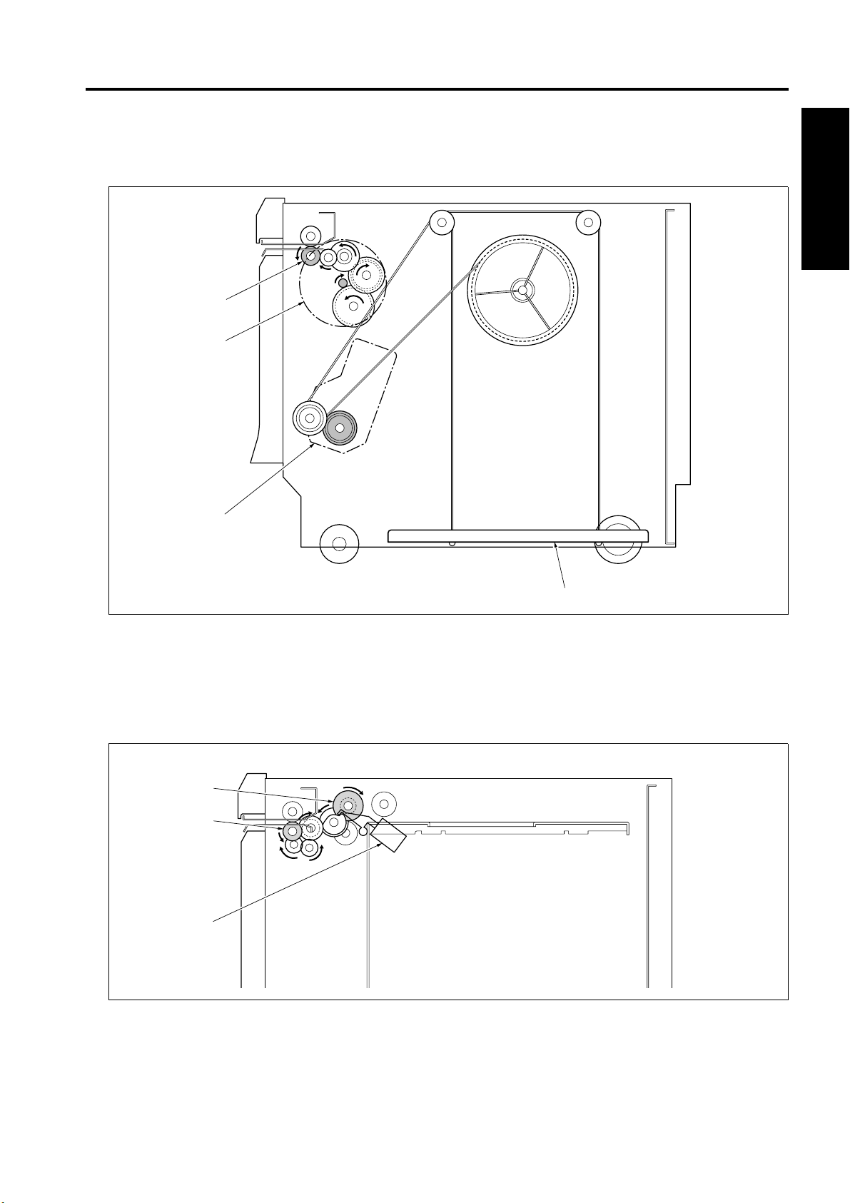
3. DRIVE SYSTEM DIAGRAM
3.1 Rear side drive
[4]
[3]
DRIVE SYSTEM DIAGRAM
I OUTLINE
[2]
[1]
[1] Paper lift plate [3] M150 (LT paper feed motor)
[2] M151 (Tray up drive motor) [4] Conveyance roller
3.2 Front side drive
[3]
[2]
[1]
[1] SD151 (LT paper feed solenoid) [3] Feed roller
[2] Conveyance roller
1-3
Page 10

DRIVE SYSTEM DIAGRAM
I OUTLINE
Blank page
1-4
Page 11

II UNIT EXPLANATION
1. PAPER FEED SECTION
1.1 Composition
PAPER FEED SECTION
LTDB
[8]
M150
SD151
[10] [11] [12][9]
[13]
[1]
II UNIT EXPLANATION
[2]
[3]
[7]
[6] [4] , [5]
Symbol Name Function or method
[1] MS151 (Interlock switch) Turns ON and OFF the 24VDC power source in interlock-
ing with the tray cover.
[2] PS154 (Remaining paper sensor /1) Remaining paper detection
[3] PS151 (Remaining paper sensor /2) Remaining paper detection
[4] PS153 (No paper sensor) Detection of the presence of paper
[5] PS152 (Tray upper limit sensor) Paper upper limit detection
[6] Double feed prevention roller Prevent double feed of paper, Torque limiter
[7] M151 (Tray up drive motor) Tray drive, 24VDC brush motor
[8] Actuator LT set detection actuator
[9] PS155 (Paper feed sensor) Detection of the presence of paper
[10] Conveyance roller Paper conveyance
[11] Feed roller Paper conveyance
[12] Paper feed roller Paper conveyance
[13] Paper lift plate Lifting up of paper
2-1
Page 12

PAPER FEED SECTION
Symbol Name Function or method
M150 LT paper feed motor Driving of the 1st paper feed system, 24VDC brushless
SD151 LT paper feed solenoid Transmission of the 1st paper feed driving force
1.2 Operation
1.2.1 Tray up drive control
When the tray cover is closed, the tray up drive coupling projects to interlock with the M151 (Tray up drive
motor). Also, the tray cover turns on the MS151 (Interlock switch) to supply a 24VDC power to the drive
system. As a result, the M151 goes on to lift the paper lift plate.
When the PS152 (Tray upper limit sensor) is turned on to detect the paper upper limit, the M151 goes off.
When paper is fed and the PS152 is turned off, the M151 lifts the paper lift plate until the PS152 is turned
on again. When the tray cover is opened, the cover wire is pulled to release the tray up drive coupling.
II UNIT EXPLANATION
Then, the paper lift plate goes down to the position where the weight of paper is balanced with the tension
of the wire fixing spring.
motor PLL control
1.2.2 Paper feed control
The paper feed system is driven by the M150 (LT paper feed motor). When the SD151 (LT paper feed
solenoid) is turned on, the 1st paper feed section feeds paper to the registration section.
2-2
Page 13

PAPER FEED SECTION
1.2.3 Remaining paper detection control
The remaining paper quantity is detected by the PS151 (Remaining paper sensor /2) and the PS154
(Remaining paper sensor /1). The paper lift plate goes up gradually as the quantity of paper in the tray is
getting reduced. Interlocking with the paper lift plate that goes up, the actuator at the rear of the tray
rotates. The remaining paper quantity is detected by the PS151 and the PS154 when they are turned on
and off by the actuator.
No paper detection is made by the PS153 (No paper sensor).
Remaining paper in the tray PS151 PS154
Full !
Medium !!
Low !
!: Sensor on
[5]
[4]
[3]
[1]
[2]
[1] Actuator [4] Rotating direction when the tray goes up
[2] PS151 (Remaining paper sensor /2) [5] PS153 (No paper sensor)
[3] PS154 (Remaining paper sensor /1)
II UNIT EXPLANATION
2-3
Page 14

PAPER FEED SECTION
II UNIT EXPLANATION
Blank page
2-4
Page 15
III DISASSEMBLY/ASSEMBLY
Caution:
• Make sure the power cord of the copier is
unplugged from the power outlet before dis-
assembly or assembly.
1. PAPER FEED SECTION
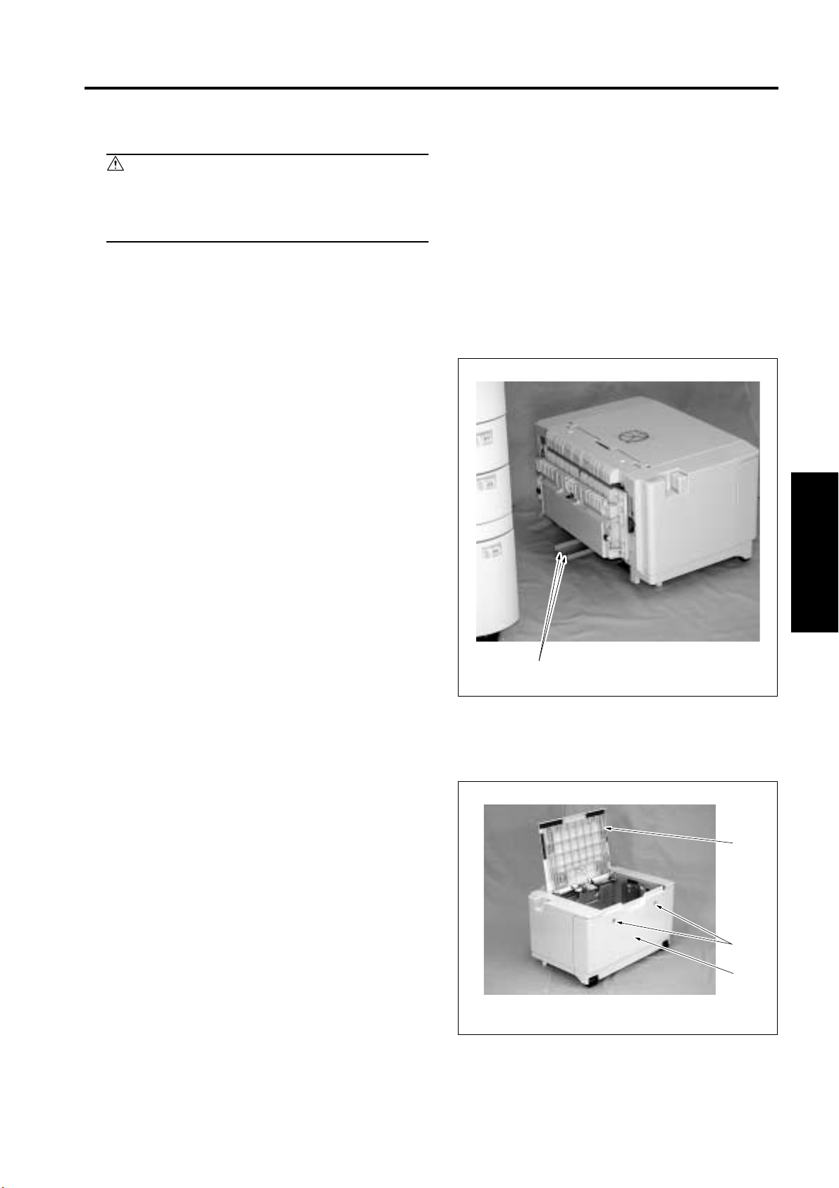
1.1 Removing the LT
1. Pull the LT out of the main body.
2. Remove the 2 screws [1], and remove the LT
from the main body.
PAPER FEED SECTION
1.2 Removing the right, front and rear covers
1. Pull out the LT from the main body.
2. Open the top cover [1], remove the 2 screws [2]
and remove the right cover [3].
III DIS./ASSEMBLY
[1]
[1]
[2]
[3]
3-1
Page 16

PAPER FEED SECTION
3. Remove the 4 screws [1], and remove the front
cover [2].
4. Remove the 3 screws [1] and remove the cable
cover [2].
5. Remove the 4 screws [3], and remove the rear
cover [4].
6. Reinstall the above parts following the removal
steps in reverse.
[1]
[2]
[1]
[4]
[3]
III DIS./ASSEMBLY
[3]
Note:
• Install the right cover so that the casters [1] (front
and rear) on the right side turn in the direction
shown in the drawing.
[1][2]
[1]
3-2
Page 17

1.3 Replacing the feed rubber and the paper feed rubber
A. Periodically replaced parts/cycle
• Feed rubber: Every 240,000 copies (once for
every 200,000 copies for actual durable count)
• Paper feed rubber: Every 240,000 copies (once
for every 200,000 copies for actual durable
count)
B. Procedure
1. Open the tray cover [1].
2. Remove the 2 stop rings [2]. Slide the bearing
on the front [3] and that on the rear [4] to the
outside and remove the paper feed roller unit
[5].
PAPER FEED SECTION
[1][2]
3. Remove the 2 stop rings [1] and remove the
actuator [2] and the bearing [3].
4. Pull out the feed shaft [4].
5. Remove the feed rubber [6] from the feed roller
[5].
6. Remove the stop ring [7] and pull out the paper
feed shaft [8].
7. Remove the paper feed rubber [10] from the
paper feed roller [9].
Note:
• Be sure to install the feed rubber [6] so that the
paint mark [11] turns in the direction shown in the
drawing.
[3] [4][5]
[5]
[4]
III DIS./ASSEMBLY
[11]
[6]
[1]
[3]
[2]
[7]
[10]
[9][8]
3-3
Page 18

PAPER FEED SECTION
8. Reinstall the above parts following the removal
steps in reverse.
Note:
• When installing the paper feed roller unit, be sure
to put the paper feed shaft [1] securely into the
ring [3] of the actuator on the front side after
passing it under the paper feed roller release arm
[2].
• Install the paper feed roller unit so that the hook
[4] of the paper feed roller holder comes above
the paper feed roller release arm [2].
• Be sure to put the feed shaft [5] securely into the
coupling shaft [6].
[5]
[4]
[6]
[2]
[1]
[3]
III DIS./ASSEMBLY
3-4
Page 19

1.4 Replacing the double feed prevention rubber
A. Periodically replaced parts/cycle
• Double feed prevention rubber: Every 240,000
copies (once for every 200,000 copies for actual
durable count)
B. Procedure
1. Pull out the LT from the main body.
2. Open the tray cover [1].
3. Remove the 2 screws [2], and remove the cover
[3].
PAPER FEED SECTION
[1]
4. Remove the screw [1] from the left side.
[2][3]
[1]
III DIS./ASSEMBLY
3-5
Page 20

PAPER FEED SECTION
5. Pushing the knobs [1] on both sides with your
fingers and remove the double feed prevention
roller unit [2].
[1][2][1]
6. Pull out the shaft [1] while pressing the lever of
the shaft [1].
7. Remove the double feed prevention rubber [3]
from the double feed prevention roller [2].
III DIS./ASSEMBLY
Note:
• Be sure to install the double feed prevention rub-
ber [3] so that the paint mark [4] turns in the direc-
tion as shown in the drawing.
[4]
[3]
[2]
[1]
3-6
Page 21

8. Reinstall the above parts following the removal
steps in reverse.
PAPER FEED SECTION
Note:
• When installing the double feed prevention roller
unit, be sure to align the upper section of the claw
[1] with the center (the longest scale) of the mark-
ing [2] impressed on the plate for leveling.
[2]
[1]
III DIS./ASSEMBLY
3-7
Page 22

PAPER FEED SECTION
1.5 Replacing the wire
Wire length
Wire/A : 707.2mm
Wire/B : 585.7mm
Wire/C : 558.7mm
Wire/D : 680.2mm
Assist wire : 706.3mm
Detection wire : 609.6mm
A. Removing wires
1. Pull out the LT from the main body.
2. Remove the right, front and rear covers.
3. Remove the 3 connectors [1].
4. Remove the 2 screws [2], and remove the cable
[3].
[1]
III DIS./ASSEMBLY
[2] [3]
5. Remove the 6 screws [1] and remove the LT
drive board unit [2].
[1] [2]
[1]
3-8
Page 23

6. Remove the 2 washers [1].
Note:
• Since the washers may have stuck to the
removed LT drive board unit side, don’t lose
them.
PAPER FEED SECTION
[1]
7. Remove the 3 screws [1], and remove the M151
(Tray up drive motor) [2].
8. Remove the 4 screws [1], and remove the wire
drive shaft bracket [2].
[2]
[1]
III DIS./ASSEMBLY
[2]
3-9
[1]
[1]
Page 24

PAPER FEED SECTION
9. Remove the E-ring [1], and remove the wire
stopper [2].
10. Remove the assist wire [4] from the spring [3].
Note:
• Be careful that the paper lift plate [5] comes down
by its own weight.
11. Peel off the seal [7] from the detection reel [6].
12. Rotate the detection reel [6] clockwise as seen
from the rear side, and remove the detection
wire [8] from the reel.
[8][6]
[7]
C
D
B
A
[3]
[4]
[5]
[2]
[1]
III DIS./ASSEMBLY
3-10
Page 25

13. Remove the 2 E-rings [1] and the 2 wire stop-
pers [3].
14. Remove the 4 E-rings [4] and remove the 4
upper pulleys [5].
[1]
[2]
PAPER FEED SECTION
[2]
[1]
C
D
B
A
15. Remove the E-ring [1] and the drive pulley [2],
then remove the assist wire [3], the wire A [4]
and the wire B [5].
16. Remove the E-ring [6] and the drive pulley [7],
then remove the detection wire [8], the wire D
[9] and the wire C [10].
[1]
[2]
[3]
[4]
[4]
[5]
[4]
[5]
III DIS./ASSEMBLY
C
D
B
A
[10]
[5]
A
B
[9]
D
C
[8]
[7]
[6]
3-11
Page 26

PAPER FEED SECTION
B. Stringing wires
1. Pass the wire A [1], the wire B [2], the wire C [3]
and the wire D [4] through the paper lift plate [5].
2. There are 2 upper pulleys and 2 lower pulleys
provided. Run the wire A [6] and the wire B [7]
through each of the upper pulleys [8] and the
lower pulleys [9], and then through the adjust-
ment part [10].
3. Tighten the 2 upper pulleys [8] with the 2 E-rings
[11].
4. Install the wire stopper [12] to each of the 2
lower pulleys [9] in the direction as shown in the
drawing. And then fasten it with the E-ring [13].
5. Run the wire C [14] and the wire D [15] through
the groove of the pulley [16].
6. Tighten the 2 pulleys [16] with the 2 E-rings [17].
[6]
AA
[6][7]
B
[11][8][11]
[10]
B
[2]
[1]
[8]
[14] [15] [15]
C
[17][16]
C
[3]
A
DD
[17][16]
[4]
D
[5]
[9]
[12]
[13]
[9]
[12]
[13]
III DIS./ASSEMBLY
7. After putting the assist wire [1], the wire A [2]
and the wire B [3] into the holes in the front sec-
tion of the drive shaft [4], install the drive pulley
[5] and tighten it with the E-ring [6].
8. After putting the detection wire [7], the wire D [8]
and the wire C [9] into the holes in the rear sec-
tion of the drive shaft [4], install the drive pulley
[10] and tighten it with the E-ring [11].
B
C
D
A
[9]
[6]
[1]
[5]
[2]
[3]
A
B
[8]
D
C
[7]
[10]
[11]
[4] [4]
3-12
Page 27

9. From the left side of the LT, hold the drive pulley
[1] and the drive pulley [2] with both hands and
rotate them to the front side (counterclockwise
as seen from the front) until there are no slacks
found in the wires A, B, C, and D.
10. Rotate the coupling shaft [3] on the rear side to
lift the paper lift plate [4] to the upper limit.
PAPER FEED SECTION
[7]
[9]
[10]
[3]
[2]
Note:
• Be sure to wind the wires from the inside of the LT
to the outside.
At this time, the assist wire [5] and the detection
wire [11] should not have been wound around the
drive pulleys [6] and [12].
11. Wind the assist wire [5] about half turn counter-
clockwise around the drive pulley [6].
12. Wind the assist wire [5] a full turn clockwise
around the pulley [7] and install it to the spring
[8].
13. Install the wire stopper [9] to the pulley [7] in the
direction as shown in the drawing, and tighten it
with the E-ring [10].
14. With the paper lift plate [4] lifted fully up to the
upper limit, wind the detection wire [11] about
half turn clockwise around the drive pulley /R
[12].
15. Set the wire attaching notch [2] at the right
above position with no tension applied on the
detection reel [1], and wind the detection wire [3]
a turn counterclockwise around the detection
reel [1] starting at the top side.
[1]
[5]
[6]
[8]
C
D
B
A
[4]
[11][5]
[12]
III DIS./ASSEMBLY
[2]
Note:
• Be sure to wind the wire from the inside of the LT
to the outside.
16. Rotate the detection reel [1] clockwise to apply
tension. After rotating about 3/4 turns, install the
detection wire [3].
17. Stick the seal [4] to the detection reel [1].
18. For reinstallation, follow Steps 1 to 8 in “A.
Removing the wire” in reverse order.
3-13
[1]
[4] [3]
Page 28

PAPER FEED SECTION
Note:
• After finishing wire replacement or rewiring, move
the paper lift plate up and down by hand to con-
firm that moves smoothly.
• Make sure that the wires do not cross each other,
or a wire does not run on another wire.
• After installing the wires, adjust “LT tray tilt adjust-
ment”.
III DIS./ASSEMBLY
3-14
 Loading...