

Page 1

SERVICE MANUAL
MODELS
KN-302/302A/306
Network Interface Cards
FEBRUARY 2002
CSM-KN302/302A/306
Page 2

Page 3
SAFETY AND IMPORTANT WARNING ITEMS
SAFETY AND IMPORTANT WARNING ITEMS
Read carefully the Safety and Important Warning Items described below to understand them before doing service work.
IMPORTANT NOTICE
Because of possible hazards to an inexperienced person servicing this print controller units as well as the risk of
damage to the print controller units, Konica Corporation strongly recommends that all servicing be performed
only by Konica-trained service technicians.
Changes may have been made to this print controller units to improve its performance after this Service Handbook was printed. Accordingly, Konica Corporation does not warrant, either explicitly or implicitly, that the information contained in this Service Handbook is complete and accurate.
The user of this Service Handbook must assume all risks of personal injury and/or damage to the controller
product while servicing the controller product for which this Service Handbook is intended.
Therefore, this Service Handbook must be carefully read before doing service work both in the course of technical training and even after that, for performing maintenance and control of the print controller units properly.
Keep this Service Handbook also for future service.
When it is impossible to read the description about safety and warning (due to contamination or tear), the rele-
vant page should be replaced.
DANGER, WARNING, AND CAUTION SYMBOLS
AND EXPRESSIONS
In this Service Handbook, each of three expressions " DANGER," " WARNING," and " CAUTION" is
defined as follows together with a symbol mark to be used in a limited meaning.
When servicing the print controller units, the relevant works (disassembling, reassembling, adjustment, repair,
maintenance, etc.) need to be conducted with utmost care.
DANGER:Action having a high possibility of suffering death or serious injury
WARNING:Action having a possibility of suffering death or serious injury
AUTION:Action having a possibility of suffering a slight wound, medium trouble,
and property damage
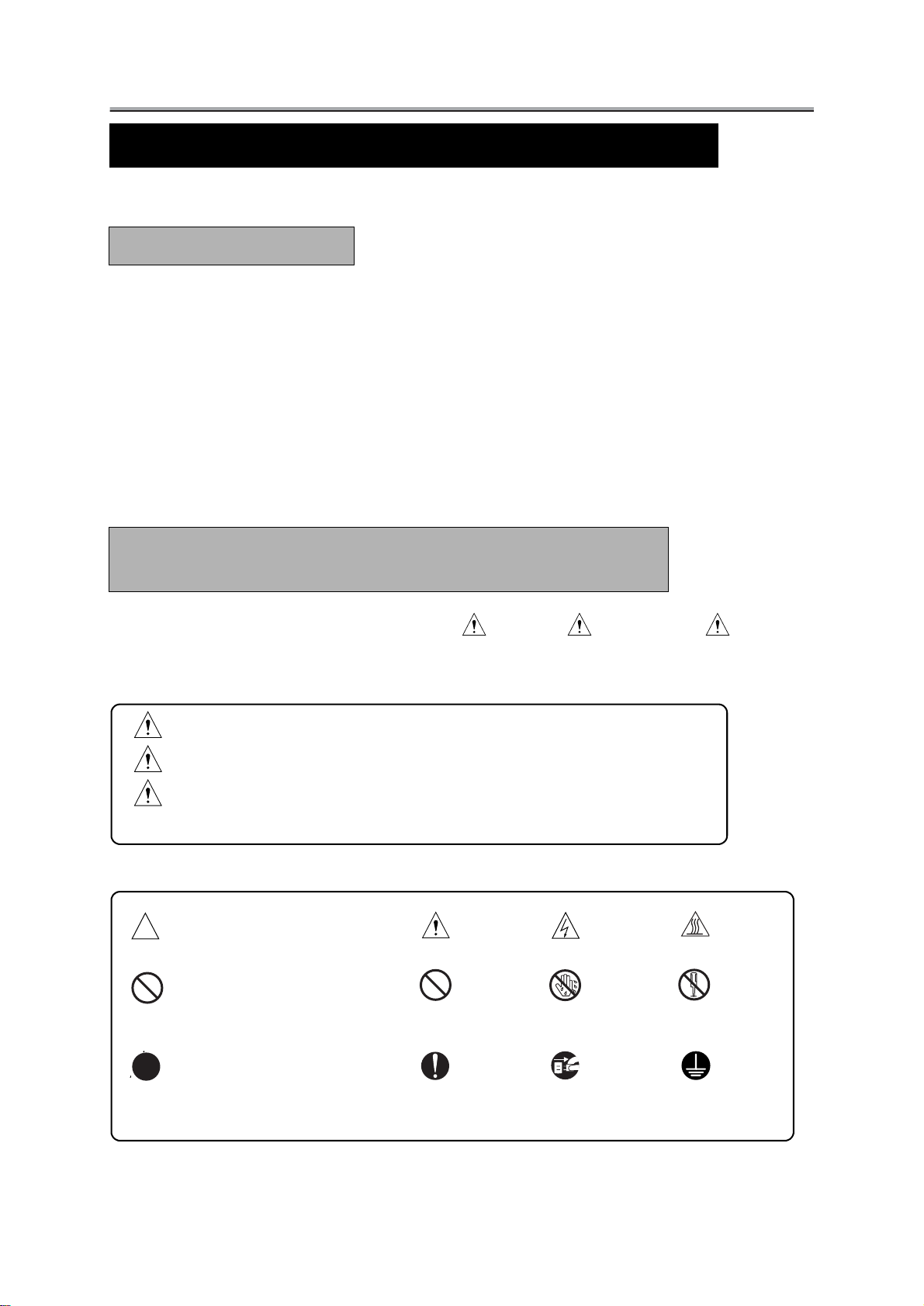
Symbols used for important warning items are defined as follows:
Precaution
General precaution Electric shock Heated surface
Prohibition
General prohibition Do not touch with wet
hand
Do not disassemble
Direction
General instruction Unplug
Ground/Earth
Page 4
SAFETY AND IMPORTANT WARNING ITEMS
SAFETY WARNINGS
[1] MODIFICATIONS NOT AUTHORIZED BY KONICA
Konica controllers for copier are renowned for their high reliability. This reliability is achieved through high-quality design and a solid service network.
Print controller units design is a highly complicated and delicate process where numerous mechanical, physical,
and electrical aspects have to be taken into consideration, with the aim of arriving at proper tolerances and
safety factors. For this reason, unauthorized modifications involve a high risk of degradation in performance and
safety. Such modifications are therefore strictly prohibited. the points listed below are not exhaustive, but they
illustrate the reasoning behind this policy
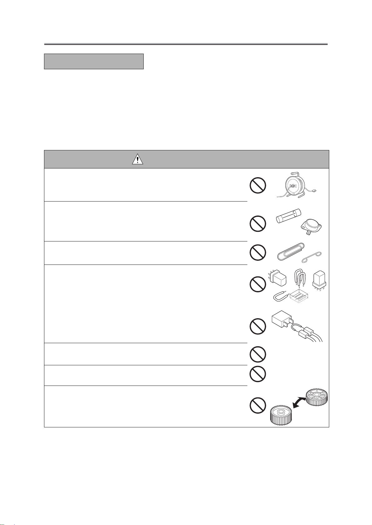
PROHIBITED ACTIONS:
• Using any cables or power cord not specified by Konica.
• Using any fuse or thermostat not specified by Konica. Safety will not be
assured, leading to a risk of fire and injury.
• Disabling fuse functions or bridging fuse terminals with wire, metal clips,
solder or similar object
• Disabling relay functions (such as wedging paper between relay contacts).
• Disabling safety functions (interlocks, safety circuits, etc.) Safety will not
be assured, leading to a risk of fire and injury.
• Making any modification to the print controller units unless instructed by
Konica
• Using parts not specified by Konica.
Page 5
SAFETY AND IMPORTANT WARNING ITEMS
[2] CHECKPOINTS WHEN PERFORMING ON-SITE SERVICE
Print controller units are extensively tested before shipping, to ensure that all applicable safety standards are
met, in order to protect the customer and customer engineer (hereafter called the CE) from the risk of injury.
However, in daily use, any electrical equipment may be subject to parts wear and eventual failure. In order to
maintain safety and reliability, the CE must perform regular safety checks.
1. Power Supply
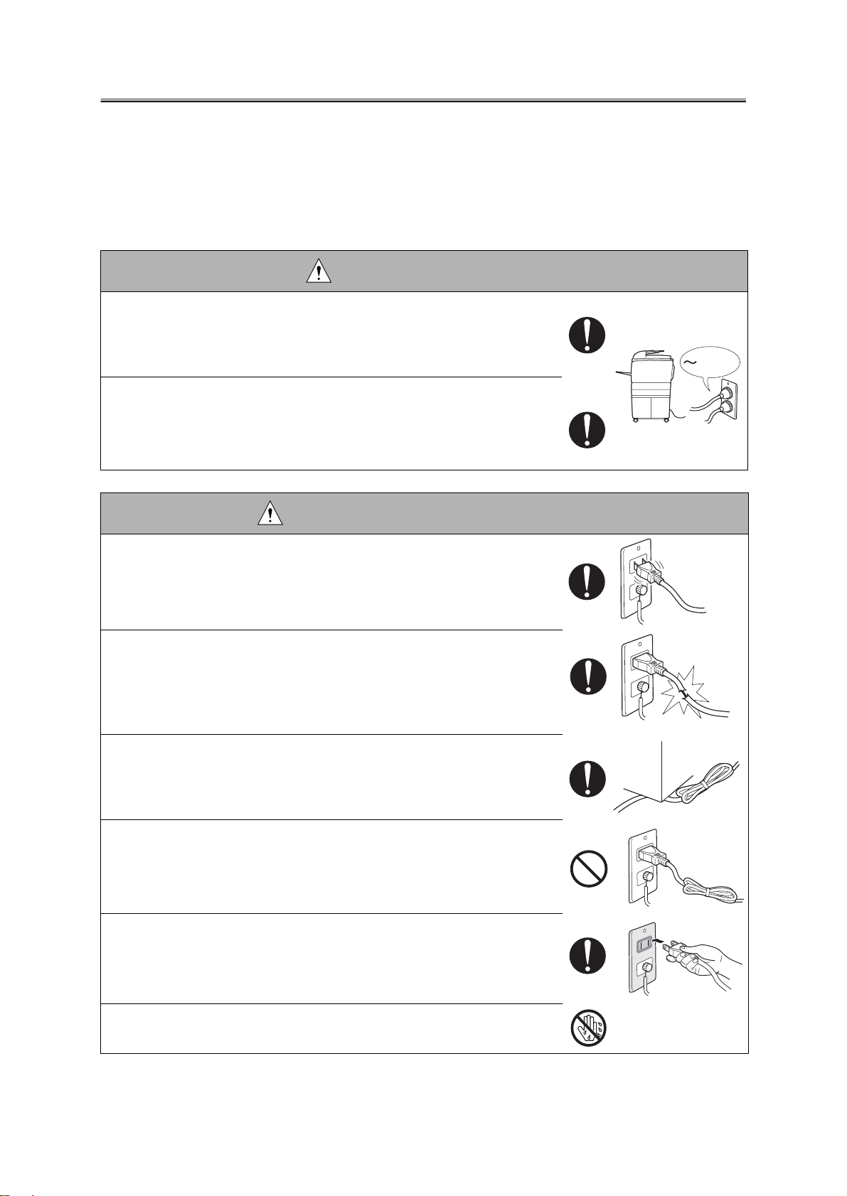
WARNING: Wall Outlet
• Check that mains voltage is as specified. Plug the power cord into the
dedicated wall outlet with a capacity greater than the maximum power
consumption.
If excessive current flows in the wall outlet, fire may result.
• If two or more power cords can be plugged into the wall outlet, the total
load must not exceed the rating of the wall outlet.
If excessive current flows in the wall outlet, fire may result.
kw
WARNING: Power Plug and Cord
• Make sure the power cord is plugged in the wall outlet securely.
Contact problems may lead to increased resistance, overheating, and
the risk of fire.
• Check whether the power cord is damaged. Check whether the sheath is
damaged.
If the power plug, cord, or sheath is damaged, replace with a new power
cord (with plugs on both ends) specified by Konica. Using the damaged
power cord may result in fire or electric shock.
• Check whether the power cord is not stepped on or pinched by a table and
so on.
Overheating may occur there, leading to a risk of fire.
• Do not bundle or tie the power cord.
Overheating may occur there, leading to a risk of fire.
• Check whether dust is collected around the power plug and wall outlet.
Using the power plug and wall outlet without removing dust may result
in fire.
• Do not insert the power plug into the wall outlet with a wet hand.
The risk of electric shock exists.
Page 6
SAFETY AND IMPORTANT WARNING ITEMS
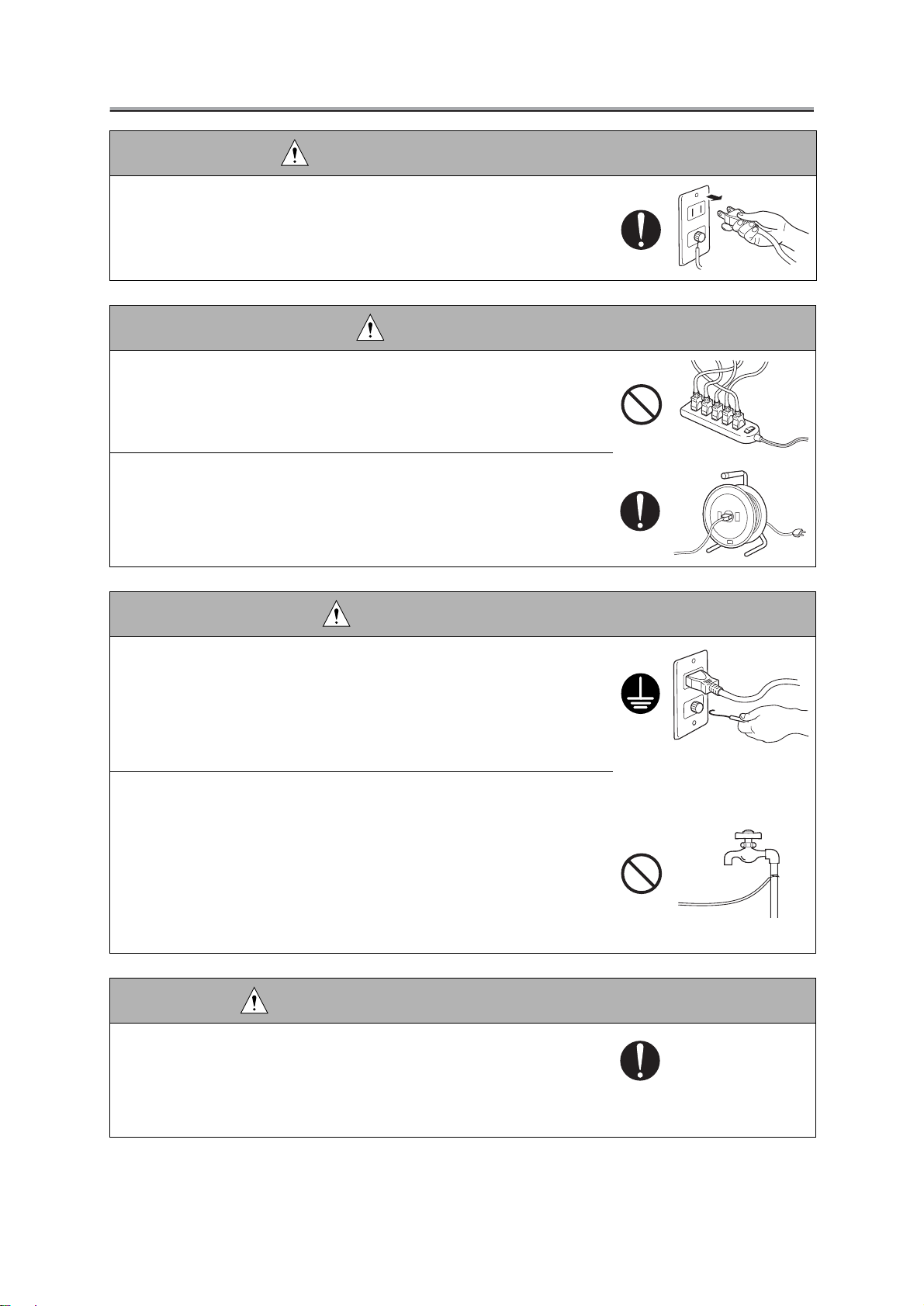
WARNING: Power Plug and Cord
• When unplugging the power cord, grasp the plug, not the cable.
The cable may be broken, leading to a risk of fire and electric shock.
WARNING: Wiring
• Never use multi-plug adapters to plug multiple power cords in the same
outlet.
If used, the risk of fire exists.
• When an extension cord is required, use a specified one.
Current that can flow in the extension cord is limited, so using a too long
extension cord may result in fire.
Do not use an extension cable reel with the cable taken up. Fire may
result.
WARNING: Ground Lead
• Check whether the copier / print controller units are grounded properly.
If current leakage occurs in an ungrounded copier / print controller units,
you may suffer electric shock while operating the copier / print controller
units. Connect the ground lead to one of the following points:
a. Ground terminal of wall outlet
b. Ground terminal for which Class D work has been done
• Pay attention to the point to which the ground lead is connected.
Connecting the ground lead to an improper point such as the points
listed below results in a risk of explosion and electric shock:
a.Gas pipe (A risk of explosion or fire exists.)
b. Lightning rod (A risk of electric shock or fire exists.)
c. Telephone line ground (A risk of electric shock or fire exists in the
case of lightning.)
d. Water pipe or faucet (It may include a plastic portion.)
CAUTION: Power Supply Voltage Setting
• When installing a unit which is equipped to operate on manual setting for
power supply and voltage, make sure certainly that the input voltage
selection matches to the line voltage at the installation site.
Operating a product on voltages different from the specified one may
result in malfunctioning or fire.
Page 7
SAFETY AND IMPORTANT WARNING ITEMS
2. Installation Requirements
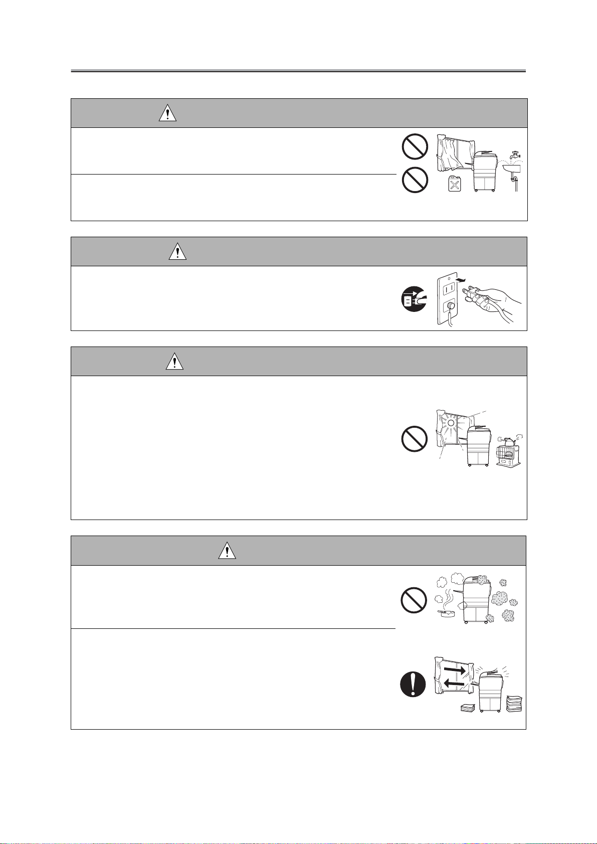
WARNING: Prohibited Installation Place
• Do not place the copier / print controller units near flammable materials
such as curtains or volatile materials that may catch fire.
A risk of fire exists.
• Do not place the copier / print controller units in a place exposed to water
such as rain water.
A risk of fire and electric shock exists.
WARNING: Nonoperational Handling
• When the copier / print controller units are not used over an extended
period of time (holidays, etc.), switch it off and unplug the power cord.
Dust collected around the power plug and outlet may cause fire.
CAUTION: Temperature and Humidity
• Do not place the copier / print controller units in a place exposed to direct
sunlight or near a heat source such as a heater.
A risk of degradation in copier / print controller units performance or
deformation exists.
Do not place the copier /
wind.
Recommended temperature and humidity are as follows:
Temperature: 10
Humidity: 10% to 80% (no dew condensation)
Avoid other environments as much as possible.
print controller units in a place exposed to cool
°C to 30°C
CAUTION: Ventilation
• Do not place the copier / print controller units in a place where there is
much dust, cigarette smoke, or ammonia gas.
Place the copier /
vent machine problems and image faults.
• The copier generates ozone gas during operation, but it is not sufficient to
be harmful to the human body.
If a bad smell of ozone is present in the following cases, ventilate the
room.
a. When the copier is used in a poorly ventilated room
b. When taking a lot of copies
c. When using multiple copiers at the same time
print controller units in a well ventilated place to pre-
Page 8
SAFETY AND IMPORTANT WARNING ITEMS
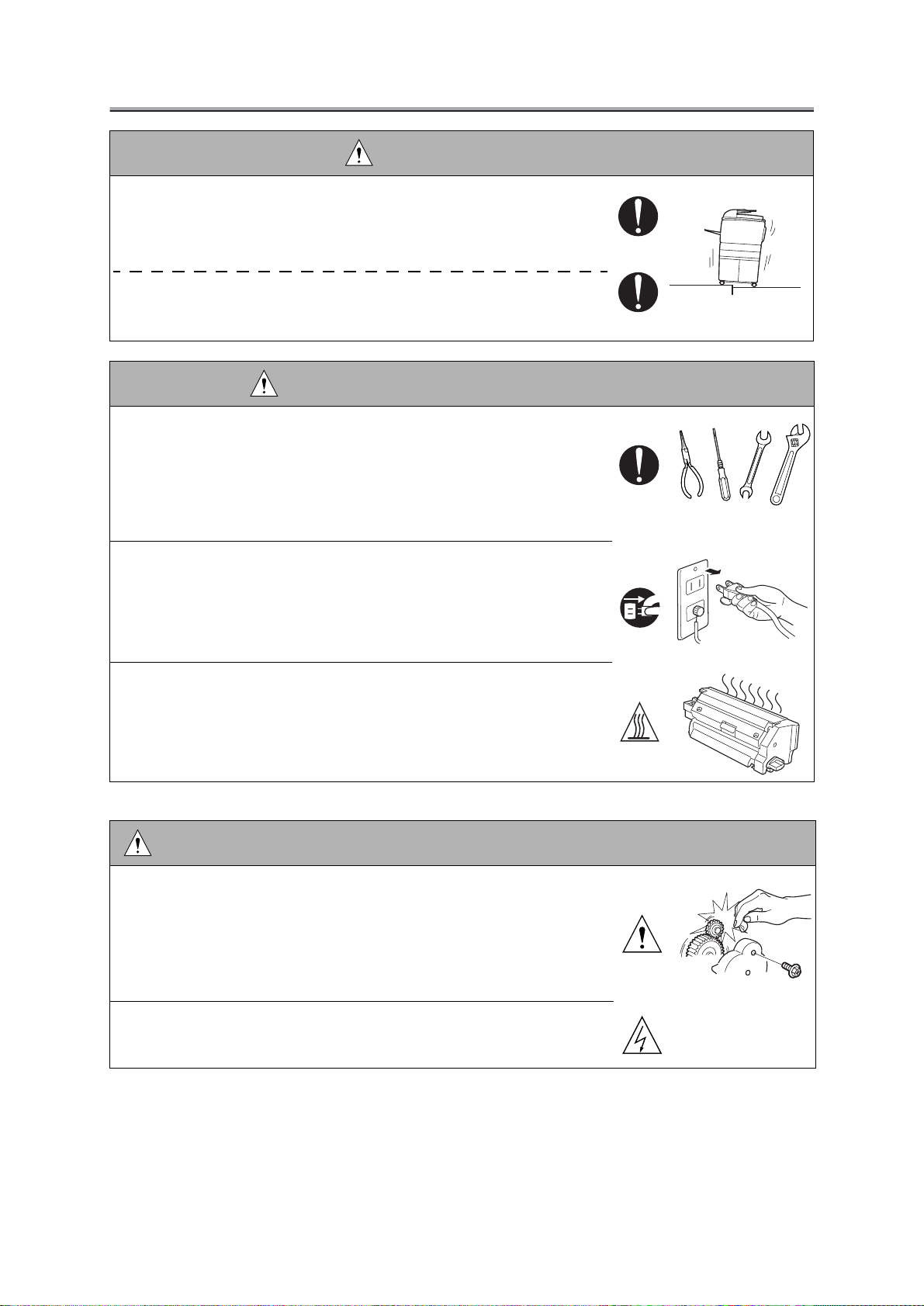
CAUTION: Vibration
• When installing the copier / print controller units, read the Installation
Guide thoroughly. Be sure to install the copier /
level and sturdy place.
Constant vibration will cause problems.
• Be sure to lock the caster stoppers of copier / print controller units.
In the case of an earthquake and so on, the copier / print controller units
may slide, leading to a injury.
print controller units in a
CAUTION: Inspection before Servicing
• Before conducting an inspection, read all relevant documentation (service
handbook, technical notices, etc.) and proceed with the inspection following the prescribed procedure, using only the prescribed tools. Do not
make any adjustment not described in the documentation.
If the prescribed procedure or tool is not used, print controller units may
break and a risk of injury or fire exists.
• Before conducting an inspection, be sure to disconnect the power plugs
from the copier and
When the power plug is inserted in the wall outlet, some units are still
powered even if the POWER switch is turned OFF. A risk of electric
shock exists.
• The area around the fixing unit is hot.
You may get burnt.
print controller units.
DANGER: Work Performed with the Copier / Print controller units Powered
• Take every care when making adjustments or performing an operation
check with the copier / print controller units powered.
If you make adjustments or perform an operation check with the external cover detached, you may touch live or high-voltage parts or you may
be caught in moving gears or the timing belt, leading to a risk of injury.
• Take every care when servicing with the external cover detached.
High-voltage exists around the drum unit. A risk of electric shock exists.
Page 9
SAFETY AND IMPORTANT WARNING ITEMS
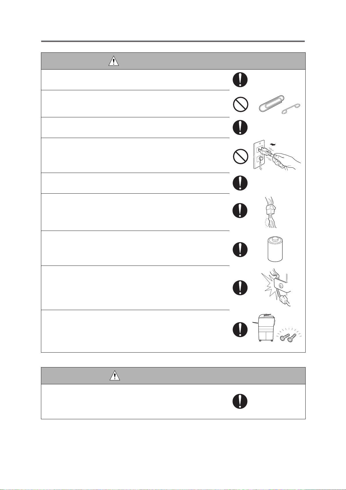
WARNING: Safety Checkpoints
• Check the exterior and frame for edges, burrs, and other damages.
The user or CE may be injured.
• Do not allow any metal parts such as clips, staples, and screws to fall into
the print controller units.
They can short internal circuits and cause electric shock or fire.
• Check wiring for squeezing and any other damage.
Current can leak, leading to a risk of electric shock or fire.
• When disconnecting connectors, grasp the connector, not the cable.
(Specifically, connectors of the AC line and high-voltage parts)
Current can leak, leading to a risk of electric shock or fire.
• Carefully remove dust from electrical parts.
Current can leak, leading to a risk of print controller units trouble or fire.
• Check cables and sheaths for any damage.
Current can leak, leading to a risk of electric shock or fire.
• When replacing a lithium battery, replace it with a new lithium battery
specified in the Parts Guide Manual. Dispose of the used lithium battery
using the method specified by local authority.
Improper replacement can cause explosion.
• Make sure the wiring cannot come into contact with sharp edges, burrs, or
other pointed parts.
Current can leak, leading to a risk of electric shock or fire.
• Make sure that all screws, components, wiring, connectors, etc. that were
removed for safety check and maintenance have been reinstalled in the
original location. (Pay special attention to forgotten connectors, pinched
cables, forgotten screws, etc.)
A risk of print controller units trouble, electric shock, and fire exists.
Xpcs?
CAUTION: Safety Checkpoints
• When transporting or storing electrical boards or electrical parts, be sure
to contain them in an anti-static packaging.
Otherwise, there is a risk that error conditions may occur.
Page 10
SAFETY AND IMPORTANT WARNING ITEMS
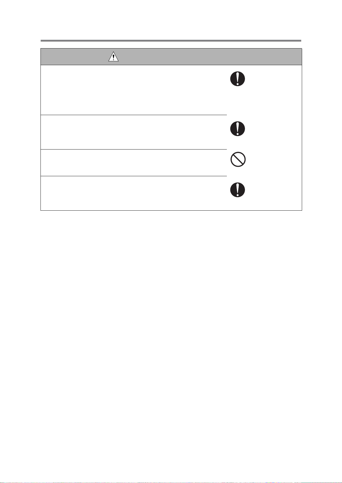
CAUTION: Safety Checkpoints
• Discharge static electricity from your body by touching metallic parts of
appropriate fixtures before starting to carry out work on a carpet or at a
location where the human body is likely to be charged with static electricity.
Otherwise, there is a risk that electrical parts can be damaged. (It is recommended that you wear an anti-static wrist strap.)
• Use a dedicated PLCC pull-out tool when removing IC parts such as PS
chips or other chips.
Using other tools may result in damaging the chip socket or the chip
itself.
• Never touch the terminal of electrical parts with hands.
To do so may result in a poor electrical conductivity. In extreme cases,
error conditions may occur.
• When inserting boars/parts into slots in electrical boards (like the PCI, ISA,
or Memory slots, for example), do so carefully and firmly.
A careless insertion may be responsible for a poor electrical conductivity. In extreme cases, error conditions may occur.
Page 11

SAFETY AND IMPORTANT WARNING ITEMS
[3] MEASURES TO TAKE IN CASE OF AN ACCIDENT
1. If an accident has occurred, the distributor who has been notified first must immediately take
emergency measures to provide relief to affected persons and to prevent further damage.
2. If a report of a serious accident has been received from a customer, an on-site evaluation must
be carried out quickly and Konica Corporation must be notified.
3. To determine the cause of the accident, conditions and materials must be recorded through
direct on-site checks, in accordance with instructions issued by Konica Corporation.
4. For reports and measures concerning serious accidents, follow the regulations given in "Serious
Accident Report/Follow-up Procedures."
[4] CONCLUSION
1. Safety of users and customer engineers depends highly on accurate maintenance and adminis-
tration. Therefore, safety can be maintained by the appropriate daily service work conducted by
the customer engineer.
2. When performing service, each print controller units on the site must be tested for safety. The
customer engineer must verify the safety of parts and ensure appropriate management of the
equipment.
Page 12

CONTENTS
Chapter 1 Overview
■ Product specifications ................................................................................ 1-1
1
● KN-302/KN-302A/KN-306 network interface card .......................................................... 1-1
● Name of each product in this manual ............................................................................. 1-1
■ Product overview ........................................................................................ 1-2
● Capabilities of the Network Interface Card ..................................................................... 1-2
Chapter 2 Disassembly / Reassembly
■ Disassembly / Reasssembly procedures .................................................. 2-1
● Installation to/removal from the Print Controller.............................................................. 2-1
Chapter 3 Troubleshooting
■ LED Status Indicator ................................................................................. 3-1
■ Status Page ............................................................................................... 3-2
Contents
■ Resetting the network interface card to Factory Default ............................. 3-4
■ How to Diagnose Problems ........................................................................ 3-5
● Troubleshooting Network Hardware Connections ........................................................... 3-6
● Troubleshooting MAP Problems ...................................................................................... 3-6
● Troubleshooting NetWare Protocol ................................................................................. 3-6
● NetWare Checklist .......................................................................................................... 3-6
● File Server Checklist ....................................................................................................... 3-6
● Workstation Checklist ..................................................................................................... 3-7
● Network Interface Card Configuration Checklist ............................................................. 3-7
● Printer Server/File Server/Printer Checklist .................................................................... 3-8
● Workstation to Network Interface Connection Checklist ................................................. 3-8
● The Network Interface Card Loses Its File Server Connection ....................................... 3-8
● Unable to Print from a Different Context ......................................................................... 3-8
Chapter 4 Appendices
■ Rewriting the firmware............................................................................. 4-1-1
● Rewrinting the firmware via the network ...................................................................... 4-1-1
● Rewrinting the firmware via the parallel port (only with KN-306) ................................. 4-1-2
■ Functions of parts mounted on the board .................................................. 4-2
■ Jumpers...................................................................................................... 4-3
INDEX .....................................................................................................Index-1
Page 13

Contents
Page 14

1
Overview
Page 15

Blank Page
Page 16

■ Product specifications
1
● KN-302/KN-302A/KN-306 network interface card
Type: Built in Konica IP-601 print controller
Built in Konica IP-601M print controller
Built in Konica IP-304 print controller
Built in Konica IP-602 print controller
Card: Network Interface Card
Network interface: Ethernet (100Base-TX/10Base-T)
Protocols: IPX/SPX (NetWare, Peer to Peer)
TCP/IP(LPD/LPR, Peer to Peer)
Dimensions: 123.7 mm (W) x 95 mm (H)
Weight: Approx. 227 g
Power source: 5 VDC (5-% to +5%,), 0.5A
Chapter 1 Overview
Note: Specifications are subject to change for improvement with-
out prior notice.
● Name of each product in this manual
The following abbreviations are used in this manual:
KN-302/KN-302A Network Interface Card
KN-306 Network Interface Card: network interface card
IP-601 Print Controller
IP-304 Print Controller
IP-601M Print Controller
IP-602 Print Controller: print controller
Konica 7055 Printer/Copier
Konica 7065 Printer/Copier
Konica 7075 Printer/Network Interface Card 1-1Copier
Konica 7085 Printer/Copier: main body printer ( or copier)
Descriptions in this manual assume a printing system made up of Konica 7075 Copier, IP-
601 Print Controller and KN-302 Network Interface Card. The disassembling/reassembling
procedure for the KN-302A/KN-306 Network Interface Card differs in some points. For de-
tails of how to disassemble/reassemble KN-302A, refer to the service handbook for the IP-
601M or IP-304 Print Controllers.For details of how to disassemble/reassemble KN-306,
refer to the service handbook for the IP-602 Print Controllers.
REVISED EDITION DATE PAGE METHOD
1
Feb 2002
1-1
REPLACEMENT
Page 17

Chapter 1 Overview
■ Product overview
● Capabilities of the Network Interface Card
The Network Interface Card allows to connect the print controller to a computer network. It receives
print jobs from the network and converts them into image data (video data) via print controller that
the copying machine prints out.
The network interface card is characterized as follows.
• Automatically selects 100Base-TX (Fast Ethernet) or 10Base-T.
• Supports peer-to-peer printing on TCP/IP and IPX/SPX from Microsoft Win-
dows 95/98.
• Supports printing by LPD/LPR of Microsoft Windows NT/2000.
• Supports both of Novell NetWare bindery mode and Novell Directory Service
(NDS).
• Incorporates an HTTP server and enable to be accessed through a standard
web browser to manage the printer and the network card. Management Ac-
cess Program (MAP) assists you to select a printer that will be displayed on
the web browser by indicating the list of printers on your network.
• Use of flash memory allows to upgrade the firmware via the network.
This Service Handbook describes hardware construction, procedures of installing/removing the
network interface card to/from the print controller, troubleshooting, and appendixes (installing
firmware, setting jumpers on the network interface card, etc).
The illustration below shows schematically how Konica 7075 Copier, IP-601 Print Controller and KN-
302 Network Interface Card are connected to form a printing system.
In case of using as a networked printer
(Network Interface Card required)
Print Controller
In case of using as a local printer
Copier
1-2 Network Interface Card
Page 18

2
Disassembly / Reassembly
Page 19

Blank Page
Page 20

Chapter 2 Disassembly / Reassembly
■ Disassembly / Reassembly procedures
● Installation to/removal from the Print Controller
Tool: Phillips screwdriver
Precautions: To shield the hard disk from detriment effects, use unmagnetized tools in the
disassembly / reassembly process. Also, without a proper ground, the card may
be damaged. Wear a wrist strap or take other proper grounding measures before
starting to work.
1
This manual provides disassembling/reassembling procedures for a printing
system made up of Konica 7075 Copier, IP-601 Print Controller and KN-302 Network
Interface Card. For guidance in disassembling/reassembling a Network Interface
Card mounted in IP-601M, IP-304 or IP-602, refer to the service handbook for the
respective print controllers.
1. Turn off the power to both the print controller and copier, and unplug the power cord of the
copier from the AC outlet.
2. Remove the left side plate from the copier.
3. Remove the cover plate from the copier.
4. Unplug the network cable, parallel cable, IEEE 1394 cable and power cord from the print
controller.
IEEE 1394 cable
Network cable
Parallel cable
5. Remove the print controller from the left side of the copier.
REVISED EDITION DATE PAGE METHOD
1
Feb 2002
2-1
REPLACEMENT
Page 21

Chapter 2 Disassembly / Reassembly
6. Remove four screws on the rear of the print controller, and remove the external cover by
sliding it backward.
7. Remove the blind plate by removing one screw.
1
Caution:
The Network Interface Card differs in mounting slot location depending on
whether it is mounted in IP-304, IP-601M or IP-602. For more about this, refer to
the Service Handbook for the respective Print Controllers.
• Slot on the 1st row from the bottom in IP-304
• Slot on the 2nd row from the bottom in IP-601M/602
8. Slide the network interface card into the PCI slot in the print controller, push it in along the
guide rail, and fasten it in place with one screw.
9. Mount the external cover back to the print controller and install the print controller to the
copier.
Uninstallation of the network interface card is made in reverse order of the installation.
REVISED EDITION DATE PAGE METHOD
1
Feb 2002
2-2
REPLACEMENT
Page 22

3
Troubleshooting
Page 23

Blank Page
Page 24

Chapter 3 Troubleshooting
■ LED Status Indicator
The network interface card has two LED status indicators: amber and green. The amber LED generally
indicates job activity; it flashes when a print job is being communicated to the Network Interface
Card; it is off when no activity is occurring.
The green LED indicates the operating condition of the network interface card when it is powered
on during normal operation. The following table provides the conditions that these LEDs indicate.
LED Patterns
Green LED is steady
ON solid.
Green LED blinks 3 times and
stays on.
Green LED
blinks rapidly.
Green LED
blinks rapidly 4
times then pauses.
Amber LED
blinks short for
10 seconds.
Amber LED goes
off and the Green
LED blinks continuously.
Green LED
blinks slowly.
Green LED
blinks rapidly.
Green LED
alternately blinks
with amber indicator.
And the printer is... Action
First powered on.
Awaiting print jobs.
Finished self-tests.
Performing self-tests.
Performing self-tests.
Performing flash
memory self-tests
Awaiting print jobs
sometime after
power-on completes.
Awaiting print jobs.
Finished power-on
sequence.
Then the network
interface card...
Is performing self-tests.
Is functioning properly.
Prints out status page
Detects defective RAM chip.
Failed the Ethernet
hardware self-test.
Check the network.
Did not pass the checksum test. Unit automatically goes into
download mode and
awaits flash update.
Some printer interface
error.
Has lost its NetWare
connection to file
server.
Has been reset to factory defaults.
Operating
Condition
Normal
Normal
Normal
Error
Error
Error
Error
Error
Error
None.
None.
None.
Replace the network
interface card.
Check the network.
Execute flash update.
Check connection
between the network
interface card
and print controller.
Check NetWare
settings.
Power off
and move jumper to
OFF position.
Network Interface Card 3-1
Page 25

Chapter 3 Troubleshooting
■ Status Page
The Status page report is sent as a print job to the printer when the network interface card is started
up completely. The Status Page described on the next page as an example shows the configuration
of the network interface card immediately before the report is printed.
It is strongly recommended that you review this report immediately after installation and any time
the setup has been changed. If the report does not include a protocol that was configured, check
that the procedure was done properly.
3-2 Network Interface Card
Page 26

Chapter 3 Troubleshooting
An example of Status Page
------------------------------------------------------------------------------------------------------------------------
Unit Serial No: 123456 Version: 05.56
Network Address: 00:11:22:33:44:55
Network Topology: Ethernet Connector: RJ45
Network Speed: 100 Megabits
Novell Network Information enabled
Print Server Name: KON_123456
Password Defined: No
Preferred Server Name not defined
Directory Services Context not defined
Frame Type: 802.2 On 802.3
Peer-to-Peer Information enabled
Frame Type: 802.2 On 802.3
Network ID: 0
TCP/IP Network Information enabled
Frame Type: Ethernet II Protocol Address: Not Configured
Subnet Mask: 255.0.0.0 Default Gateway: 0.0.0.0
DNS Address: 0.0.0.0
AppleTalk Network Information enabled
Frame Type: 802.2 SNAP On 802.3
Protocol Address: Net Number 65384 Node Number 224 Socket Number 129
Preferred AppleTalk Zone: Default Zone
------------------------------------------------------------------------------------------------------------------------
Novell inactive
Peer-to-Peer Connection Information
Printer Name: KON_123456
AppleTalk Connection Information
AppleTalk Printer Name: KON_123456
TCP/IP Connection Information
Port Number : 10001
------------------------------------------------------------------------------------------------------------------------
Network Interface Card 3-3
Page 27

Chapter 3 Troubleshooting
■ Resetting the network interface card to Factory Default
You can cause the network interface card to restore all parameters to factory default values, so the
Network Interface Card appears just as it came from the factory. You may choose to do this when
the Network Interface Card is moved to a new location where the environment (NetWare file servers,
IP subnets, and so on) is different.
This process is called “Restore Factory Defaults”. It can be done with a Web Browser. However, if
network access is not possible, another method described in [Chapter 4 Appendices]-[Jumpers] is
available.
Resetting to factory default means that the network interface card loses all data
such as names and IP address. It does not lose its serial number and MAC ad-
dress.
3-4 Network Interface Card
Page 28

Chapter 3 Troubleshooting
■ How to Diagnose Problems
Use the following list to determine the cause of printing problems:
1. Does the LCD panel of copier display an error message? Review copier INSTRUCTION MANUAL.
2. Is the printer printing? Make sure the printer is operating properly by causing it to generate a test
page. See your printer’s User’s Guide for instructions on generating a test page.
3. Is the printer on-line (green LED should light) about 2 minutes after power-on ? Verify that the
printer is on-line. Nothing will print if printer is not on-line.
4. Did you get a network interface card status page? On power-up, the network interface card
sends a status page which contains information that can be useful for troubleshooting. Keep the
status page available until a problem is resolved.
5. Check the status report to see what protocols are enabled and active. See the appropriate
chapter to confirm that you have installed and configured your network protocol correctly for the
network interface card. See An example of Status Page.
6. Check the network interface card’s LED status indicator to ensure that there is no error condition.
See LED Status Indicator, for more information.
7. Determine if other users can print. If they can’t and they are all on the same NOS, go to the
troubleshooting section for that NOS operation manual.
8. When you have determined the nature of the problem, use the checklists in the next section.
Network Interface Card 3-5
Page 29

Chapter 3 Troubleshooting
● Troubleshooting Network Hardware Connections
• For 100BaseT or 10BaseT, check that the network connector is plugged into the RJ connector on
the network interface card.
• Try another cable to make sure you do not use a defective cable.
● Troubleshooting MAP Problems
If the MAP cannot detect a target network interface card, check the following:
• Are the network settings on the network interface card correctly made?
• Did you correctly select the MAP settings?
• Are the protocol used by the computer on which the MAP to run correctly set up?
• Are the Web browser used by the computer on which the MAP to run correctly set up?
• If nothing irregular is found, turn off the main power supply to the copier, then turn it back on, wait
about several minutes and try running the MAP again.
● Troubleshooting NetWare Protocol
It is recommended you use MAP to get the NetWare setup and parameter values. If you have not
resolved the problem after running MAP, go through the checklists in this section.
● NetWare Checklist
• Is the print server name entered correctly? The factor-default name is KON_serial number. The
serial number is located on the network interface card.
• Did you set up print queues to the printer? It is recommended you assign each print queue to
only one Network Interface Card-connected printer. If print queues are assigned to other network
printers, the print jobs may be going to another network printer.
• Did you set up the printer to the type Remote Other /Unknown?
• If the PCONSOLE or NWADMIN settings are correct, the connection between the printer and
network may have been broken. Turn the printer off and, using PCONSOLE or NWADMIN, wait for
the status message Not Connected. Turn the printer on and the status should change to Waiting
for Job.
● File Server Checklist
• Is there enough disk space on the file server and is it running?
• Is the correct file server associated with the printer? Use PCONSOLE or NWADMIN to check this.
• Did you have the proper rights to configure the printer? (supervisor or administrator)
• Are the File Server and the network interface card communicating? Run NetWare’s COMCHECK
utility from any network workstation to check this.
• Are there enough user positions on the File Server? The Print Server function logs on as a user.
3-6 Network Interface Card
Page 30

Chapter 3 Troubleshooting
● Workstation Checklist
• Is the network loaded onto the workstation? See the NetWare documentation.
• Is the application set up to print to the printer? For instance, are you using the correct driver?
• Is the workstation connected to the correct print queue? Print a file and verify that the file goes to
the queue.
• Are the print queues assigned to the network interface card-connected printer also assigned to
another network printer? If they are, the print jobs may be going to that printer.
• From PCONSOLE or NWADMIN, enter a sample print job directly into an assigned queue. Does
the job become Active? Is job printed?
• Is AUTO ENDCAP enabled? Auto Endcap lets you send data to a network printer. Use PRINTCON
to check. If not, enable it.
● Network Interface Card Configuration Checklist
If all your hardware connections are correct, check the following:
• Use MAP to check the status of the network interface card. The Unit Status screen shows the
status for the selected network interface card. This report includes a status of file servers and
queues assigned to a printer along with a description of any problems.
• The printer may not be assigned to the correct print queues. Use PCONSOLE or NWADMIN to
direct print jobs to the correct queues, then check to see if the print job is in the queue.
• If devices were added or changed, use PCONSOLE or NWADMIN to make sure you configured
the new devices correctly.
• Make sure the network interface card’s name has been entered correctly. If you changed the
name with MAP, you must also change the name in PCONSOLE or NWADMIN before you can
print.
• Use PCONSOLE or NWADMIN to check the Printer Status. Make sure it is not stopped.
• You cannot PCONSOLE or NWADMIN Version1.0 to configure the network interface card. Con-
nect Novell corp. for an upgrade.
Network Interface Card 3-7
Page 31

Chapter 3 Troubleshooting
● Printer Server/File Server/Printer Checklist
Check the following to see if:
• If the Print server cannot log in to the file server, or if it is not available to process jobs from the file
server, please check the followings.
• Check to see whether the Print server is configured to the file server. Set to it by using PCONSOLE
or NWADMIN if necessary.
• The password assigned to the network interface card through PCONSOLE or NWADMIN matches
the password assigned through web browser. Use web browser to update the password stored in
the network interface card’s memory.
• The print job is in the print queue and waiting to be printed. Use PCONSOLE or NWADMIN to
check if the print jobs are being sent to the printer.
● Workstation to Network Interface Connection Checklist
To make sure the workstation is communicating with the network interface card, check the following:
• Print a file from the workstation and make sure the print job gets to the print queue using PCONSOLE
or NWADMIN. If the print job does get to the queue, the problem is not with the workstation/print
server connection.
• Use CAPTURE to send data to the printer from a workstation software application. See your NetWare
print server manual for information.
• Make sure another printer is not taking the print jobs from the queues BEFORE the network interface
card can service the job. To do this, disable the other printer until you can verify the network
interface card-connected printer setup.
● The Network Interface Card Loses Its File Server Connection
If the network interface card loses its connection to the file server, it can take approximately 5 to 10
minutes to reconnect. If the connection is not made after a reasonable amount of time, check the
error conditions to troubleshoot the problem.
● Unable to Print from a Different Context
The network interface card does not support printing from a context different from the context you
are installed upon. If you want to do this, you must create an alias queue. See your NetWare Manual
for more information.
3-8 Network Interface Card
Page 32

4
Appendices
Page 33

Blank Page
Page 34

Chapter 4 Appendices
■ Rewriting the firmware
As the network interface card uses flash ROM, KN-302 and KN-302A is possible to rewrite the
1
firmware via the network.KN-306 is possible to rewrite the firmware via the parallel port.
● Rewriting the firmware via the network (KN-302/KN-302A)
To rewrite the firmware, you use the utility program FTP Download (for TCP/IP) by the procedure
described below.
● Preparation
• Set up the following components (IBM PC/AT-compatible Windows PC) for the environment of
TCP/IP.
• Computer used to upgrade the firmware
• Network Interface Card
• Install the network interface card properly and connect its Ethernet port with a network cable
so that the network interface card can be accessed from the network computer.
• The following utility should be installed on the computer.
• FTP Download
• Prepare the replacing firmware in the hard disk of the computer or in a CD-ROM.
● Procedure of rewriting the firmware
1. Make sure of the current firmware version.
You can get the information from the status page.
2. Start FTP Download and select the firmware file (.upd file) to download from [File] menu.
<Example> g15900a.upd
You will then be urged to enter the IP address and password.
3. Enter the printer’s IP address (e.g. 192.102.51.100) and the password “sysadm” and click
the OK button.
File transfer starts.
4. When a message “Unit Updated” appears on the computer screen, click the OK button.
Caution:
Never turn off the copying machine while updating is going on.
5. Turn off the copier and wait for 10seconds, then restart it.
REVISED EDITION DATE PAGE METHOD
1
Feb 2002
4-1-1
REPLACEMENT
Page 35

Chapter 4 Appendices
● Rewriting the firmware via the parallel port (KN-306)
1
To rewrite the firmware, you use the utility program FTP Download (for TCP/IP) by the procedure
described below.
● Preparation
• Before going on, make sure of the settings the parallel port to [ECP] mode in the computer
(IBM PC/AT-compatible Windows PC)’s BIOS (This check is made on the BIOS Setup screen.
Refer to the operation manual for your computer.)
• Prepare the replacing firmware in the hard disk of the computer or in a CD-ROM.
● Procedure of rewriting the firmware
1. With the copier switched off, remove the network cable, connect a parallel cable between
the computer and the Print Controller.
2. Turn the copier’s main power on, output the Status Page and make sure of the current
firmware version.
3. Press the [MODE] button on the operation panel to switch to Printer Mode Basic screen.
4. Open a DOS prompt on the computer and input a copy command then press the Enter key.
<Example> C:\>copy firmware.xxx lpt1 /b
The message [Updating print controller F/W. Please leave the printer untouched.]
will appear on the LCD panel.
Caution:
Never turn off the copying machine while updating is going on.
5. The message [Updating Successful! Power off and restart the system.] will appear on the
LCD panel, turn off the copier and wait for 10 seconds, then restart it.
6. Output the Status Page to make sure that the firmware has been successfully rewritten.
REVISED EDITION DATE PAGE METHOD
1
Feb 2002
4-1-2
ADDITION
Page 36

Chapter 4 Appendices
■ Functions of parts mounted on the board
1
KN-302 / KN-302A/KN-306 Network Interface Card
Caution:
The board for the network interface cards is common in the 302 and 306 products.
But their CPUs differ from one another. This means that rewriting the firmware
does not eliminate incompatibility between the network interface cards for the 302
and 306 products.
Network Configuration Data maintenane (EEPROM)
Flash ROM for Network
PCI Bridge
Radiator
PA L
Green LED
Amber LED
Network Control Memory
Network Control CPU
Factory Default Settings Jumper
OP2
OP3
OP4
OP5
OP7
OP1
OP6
PHY Regulator
RJ45 Ethernet
Network port
REVISED EDITION DATE PAGE METHOD
1
Feb 2002
4-2
REPLACEMENT
Page 37

■ Jumpers
Caution:
• If grounding is not made securely, the network cards can be damaged during
work. Make sure to ground your body securely by using a wrist strap before
starting to work.
• Don’t move any jumpers other than OP2.
OP2: Reset (Factory default setting)
This allows you to restore the default values of the parameters set up before shipment.
You can reset the network interface card normally by using MAP/browser from the computer
via the network.
If you cannot use the method of using MAP/browser, perform the following procedure.
Chapter 4 Appendices
1. Turn off the copier and then remove the network interface card from the print controller.
2. Set the jumper OP2 as illustrated below. Connect the network interface card to the print
controller. And turn on the copier.
•The network interface card will restore the default settings in about 5 minutes.
OP2
OP3
OP4
OP5
OP7
OP1
OP6
3. Turn off the copier, remove the network interface card, and move the jumper OP2 back to
the position where it was set initially.
4. Connect the network interface card to the print controller, and turn on the copier.
OP2
OP3
OP4
OP5
OP7
OP1
OP6
Network Interface Card 4-3
Page 38

INDEX
INDEX
C
Context ....................................................... 3-8
D
Disassembly / Reassembly ........................ 2-1
F
Factory Default ................................... 3-4, 4-3
File Server Checklist .................................. 3-6
Firmware .................................................. 4-1-1
Flash ROM ............................................... 4-1-1
FTP Download ........................................ 4-1-1
Functions of parts mounted on the board ......
H
HTTP server ............................................... 1-2
I
IEEE 1394 cable ........................................ 2-1
4-2
P
Parallel cable .............................................. 2-1
Printer Server/File Server/Printer Checklist ........ 3-8
Product overview........................................ 1-2
Product specifications ................................ 1-1
Protocols .................................................... 1-1
R
Removal from the Print Controller ............... 2-1
Reset Factory ............................................. 3-4
Rewriting the firmware ............................ 4-1-1
Rewriting the firmware via the network ...........
Rewriting the firmware via the parallel port .....
4-1-1
4-1-2
S
Status Page......................................... 3-2, 3-3
Sysadm.................................................... 4-1-1
W
Workstation Checklist................................. 3-7
Workstation to Network Interface
Connection Checkl ..................................... 3-8
J
Jumpers ..................................................... 4-3
L
LED ............................................................ 3-1
LPR/LPD .................................................... 1-2
M
MAP ................................................... 1-2, 3-6
N
NetWare Checklist...................................... 3-6
NetWare Protocol ....................................... 3-6
Network cable ............................................. 2-1
Network Hardware Connections ................ 3-6
Network Interface Card Configuration Checklist ..... 3-7
Novell Directory Service ............................. 1-2
Novell NetWare bindery mode ................... 1-2
O
OP2: Reset ................................................. 4-3
Index-1
 Loading...