

Page 1

5
ADJUSTMENT
5. ADJUSTMENT
HOW TO USE THE ADJUSTMENT
SECTION ........................................................5-1
[1] Construction.........................................5-1
ADJUSTMENTS WHEN REPLACING
PARTS ............................................................ 5-1
LIST OF ADJUSTMENT ITEM .......................5-2
SETTING AND CHECKING WITH P
FUNCTION......................................................5-3
[1] P Button Operating Procedure............. 5-3
[2] Checking All Counter Data Information
.............................................................5-3
[3] Checking the Total Count / Start Date
.............................................................5-4
[4] Checking the PM Count / Start Date.... 5-4
[5] Checking the Drum Count....................5-4
[6] Checking the Developing Count .......... 5-4
Checking or Setting the Density Shift (text/
[7]
photo) ......................................................
[8] Checking or Setting the Density Shift
(text).....................................................5-5
[9] Checking or Setting the Density Shift
(photo)..................................................5-5
[10]Checking or Setting the Density Shift
(Increase contrast) ............................... 5-5
25 MODE ........................................................ 5-6
[1] Setting Method.....................................5-6
[2] Setting Software DIP SW..................... 5-6
[3] Tray Size Setting................................5-14
[4] PM Count Setting............................... 5-15
[5] Data Collection...................................5-16
[6] Parts counter......................................5-21
[7] Password setting................................5-26
[8] Setting Phone Number of the Service
Center ................................................5-28
5-5
[9] Setting the Serial Number.................. 5-28
[10]Displaying the ROM Version.............. 5-29
[11]KRDS Setting..................................... 5-30
[12]KRDS Set Up .....................................5-30
[13]Call setting menu mode ..................... 5-43
[14]KRDS Host Call .................................5-46
[15]KRDS Data List.................................. 5-47
[16]ISW Setting ........................................5-48
25 Mode Adjustment Item Table ..............5-51
36 MODE ...................................................... 5-52
[1] Setting Method...................................5-52
[2] High Voltage Adjustment ...................5-52
[3] Timing Adjustment ............................. 5-54
[4] Running Test Mode............................5-67
[5] Test Pattern Output............................5-68
[6] Test Pattern Density Adjustment ....... 5-75
[7] Image Quality Adjustment.................. 5-76
[8] List Print (Service data Print) ............. 5-79
36 mode adjustment items list.................. 5-80
47 MODE ...................................................... 5-92
[1] 47 Mode Setting Method....................5-92
[2] Initial Setting in the field ..................... 5-93
[3] Drum count reset ...............................5-93
[4] RADF original size detection adjustment
...........................................................5-94
[5] Electrical RDH memory check ........... 5-94
[6] RADF sensor adjustment................... 5-94
3
[7] Input check (code) list ........................ 5-95
3
[8] Output check (code) list ..................... 5-97
3
OTHER ADJUSTMENTS............................5-101
3
[1] Centering Adjustment ......................5-101
[2] Image Distortion Adjustment............ 5-102
[3] Paper Skew Adjustment...................5-104
MODEL
7040
MANUAL
SERVICE HANDBOOK
REVISED EDITION
3
DA TE
Mar. 1999
PAGE
–
METHOD
REPLACEMENT
Page 2

ADJUSTMENT
HOW T O USE THE ADJUSTMENT SECTION
[1] Construction
This section details adjusting items and procedures. Use this
section for making adjustments and as a checklist before
implementing corrective measures in the field.
1. Does the power supply meet the requirements?
2. Is the power supply properly grounded?
3. Is the machine sharing its power source with another high
current consumption machine that draws large currents
intermittently? (e.g. an elevator, air conditioner, or other
source of electrical consumption)
4. Is the installation environment suitable?
a. The machine must be installed in a well-ventilated
place free from high temperature, high humidity and
direct sunlight.
b. The machine must be installed on a level floor.
5. Does the cause of a defective image lie in the original
itself?
6. Is the density adjusting control at the proper position?
7. Are the original glass and RADF platen guide clean?
8. Is the correct paper being used for the copy?
9. Are the copying materials and parts replaced when they
reach the end of their usable life? (developer, drum,
cleaning blade, etc.)
10. Is there toner in the toner cartridge?
The following items should also be observed when repairing
the machine.
1. Only one side of the AC power line is disconnected when
the main power of this machine is turned off. Always
unplug the machine before beginning work. If absolutely
necessary to work with the power on, exercise care to
avoid being caught in the scanning rear of the exposure
unit.
2. Special care should be taken when handling the fixing unit
since it operates at extremely high temperatures.
3. The developing unit is surrounded by a strong magnetic
field. Keep watches and metering equipment away from
it.
4. Avoid scarring the drum with tools or similar objects.
5. Do not touch IC pins with your bare hands.
ADJUSTMENTS WHEN REPLACING PARTS
Adjustments (including checks) and settings are not only
required when a defective copy image occurs, but also after
replacing or reinstalling certain parts.
[How to Use the Tables]
The following items are used in the tables throughout this
section.
1. Mode
Indicates the adjustment mode.
[“25”] : 25 mode
[“36”] : 36 mode
[“47”] : 47 mode
2. Codes
Indicates the applicable code and/or Copy Quantity Setting
button for each mode.
3. Conditions
New: Indicates adjustment (including check) is required when
replacing a new part.
Reset: Indicates adjustment (including check) is required when
a part has been re-installed.
4. Symbols used in the tables
1 2 : .................. Indicates there is a priority sequence for
adjustments (including checks) and settings.
(Empty circle): Indicates adjustments (including checks)
and settings that can be carried out independently.
5 - 1
Page 3
ADJUSTMENT
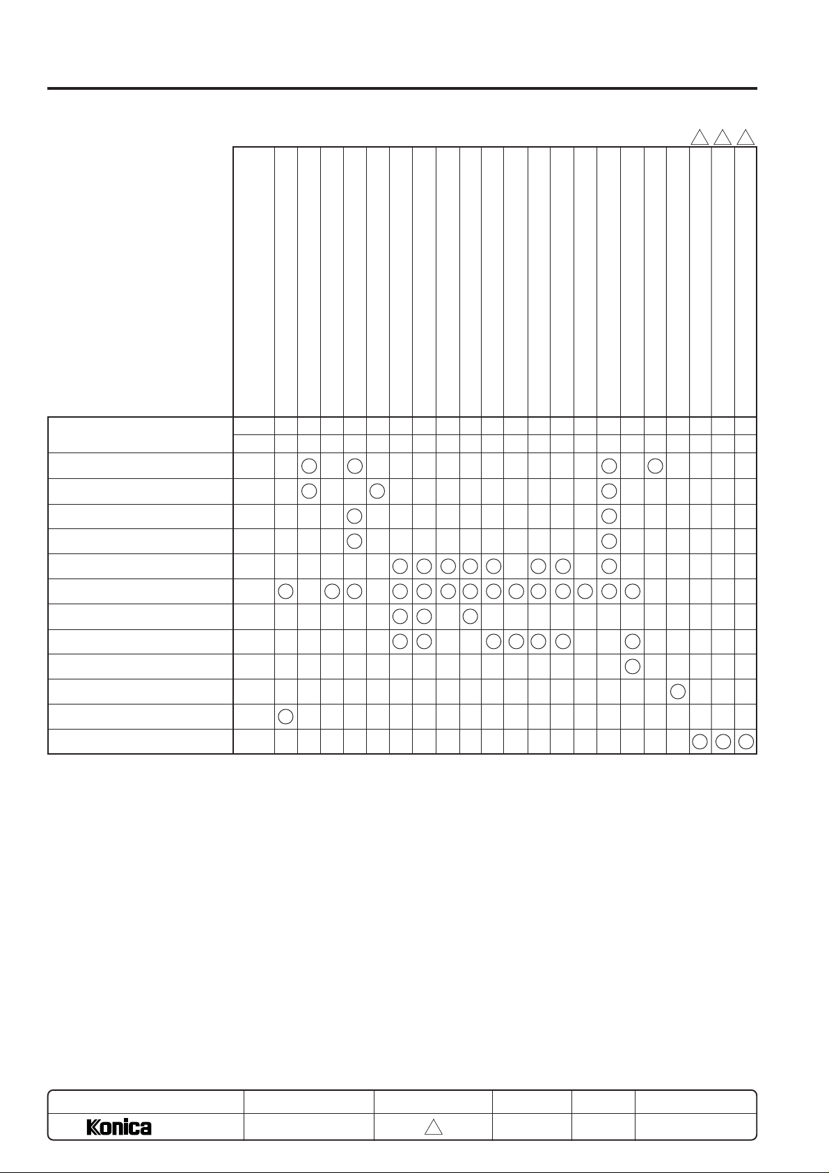
LIST OF ADJUSTMENT ITEM
Adjustment items
Tray size setting
PM count reset
PM cycle set
Charging grid voltage adjustment
L detection adjustment
Vertical magnification adjustment (Printer, Platen)
Drum
Part Name
Mode
Code252
New
25
3-1253-2361361362-1362-1362-1362-2362-2362-3362-4362-5362-6366-1366-24791-147198
2
Vertical magnification adjustment (RADF)
Horizontal magnification adjustment (Platen)
Restart timing adjustment (copier system)
Restart timing adjustment (RADF)
Paper feed loop amount adjustment
Leading edge original erasure adjustment
Centering adjustment
Image read point adjustment
PWM/Gamma correction
3
33 3
RADF scanning density adjustment
Drum count reset
Electrical RDH memory check
RADF sensor adjustment
RADF Original size adjustment (small size).
RADF Original size adjustment (large size).
47
47
69 00
47
69 01
69 02
1
Developer
Charging control plate
High voltage unit 1
Write unit
Parameter memory board
Rubber roller for paper feed unit
RADF
RADF slit glass (original glass (1))
Expansion memory
LCT (DB-608) paper size setting
DF control board
New
New
New
New/
Reinstall
New
New
New/
Reinstall
New
New/
Reinstall
–
New
1
1
1
4
1
2
3
1
2
∗
1
1
3
2
2
5
4
536
3
6
7
7
869
4
5
2
2
2
7
123
• “New” means replace with a new part and “Reinstall” means to reinstall the part.
• The circles will above a number when there is as adjustment priority.
∗ When the parameter memory board is renewed or replaced, remember to renew the developer also before conducting the L-
detection adjustment.
MODEL
7040
MANUAL
SERVICE HANDBOOK
REVISED EDITION
5 - 2
3
DATE
Mar. 1999
PAGE
5-2
METHOD
REPLACEMENT
Page 4
SETTING AND CHECKING WITH P FUNCTION
ADJUSTMENT
The P function enables display of the following parameters
using the P button.
0. Checking all counter data information
1. Checking the total count / start date
2. Checking the PM count / start date
3. Checking the Drum count
4. Checking the developing count
5. Checking or Setting the density shift (text/photo)
6. Checking or Setting the density shift (text)
7. Checking or Setting the density shift (photo)
8. Checking or Setting the density shift (Increase contrast)
This section explains the various functions which is exclusive
for the service technician.
For those used by the users, refer to “Operation section”.
[1] P Button Operating Procedure
a. Turn ON the SW1 (main power) and SW2 (sub power) to
display the basic screen.
b. Press the P button.
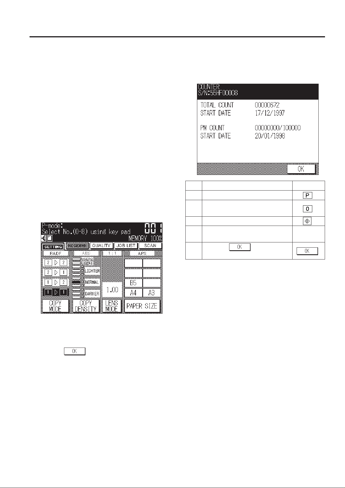
c. The P Mode Screen will appear.
[P Mode Screen]
[2] Checking All Counter Data Information
Display the total count, PM count and start date.
[Counter Check Screen]
OperationStep Operation procedure
1 Press the P button.
2 Press 0 from the copy quantity setting
button.
3 Press the Start print button.
4 Check the all counter data information
displayed in the message area.
5 Press the
basic screen.
key to return to
d. Use the copy quantity setting buttons to enter the desired
number, following the message on the operation panel.
e. Press Start print button to confirm the various data dis-
played in the message area.
f. Press the
the basic screen.
key or Stop/Clear button to return to
5 - 3
Page 5
ADJUSTMENT
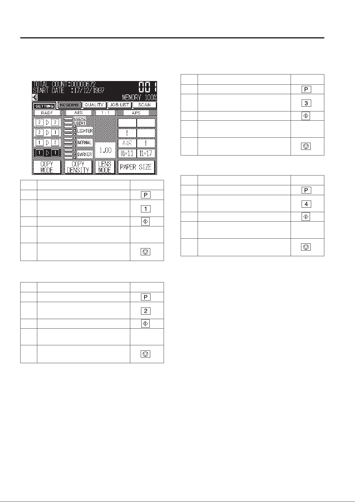
[Total Count / Start Date Check Screen]
[5] Checking the Drum Count[3] Checking the Total Count / Start Date
OperationStep Operation procedure
1 Press the P button.
2 Press 3 from the copy quantity setting
button.
3 Press the Start print button.
4 Check the drum count displayed in the
message area.
5 Press the Stop/Clear button to return
to the basic screen.
[6] Checking the Developing Count
OperationStep Operation procedure
1 Press the P button.
2 Press 1 from the copy quantity setting
button.
3 Press the Start print button.
4 Check the total count displayed in the
message area.
5 Press the Stop/Clear button to return
to the basic screen.
[4] Checking the PM Count / Start Date
OperationStep Operation procedure
1 Press the P button.
2 Press 2 from the copy quantity setting
button.
3 Press the Start print button.
4 Check the PM count displayed in the
message area.
5 Press the Stop/Clear button to return
to the basic screen.
OperationStep Operation procedure
1 Press the P button.
2 Press 4 from the copy quantity setting
button.
3 Press the Start print button.
4 Check the developing count displayed
in the message area.
5 Press the Stop/Clear button to return
to the basic screen.
5 - 4
Page 6
ADJUSTMENT
[7] Checking or Setting the Density Shift
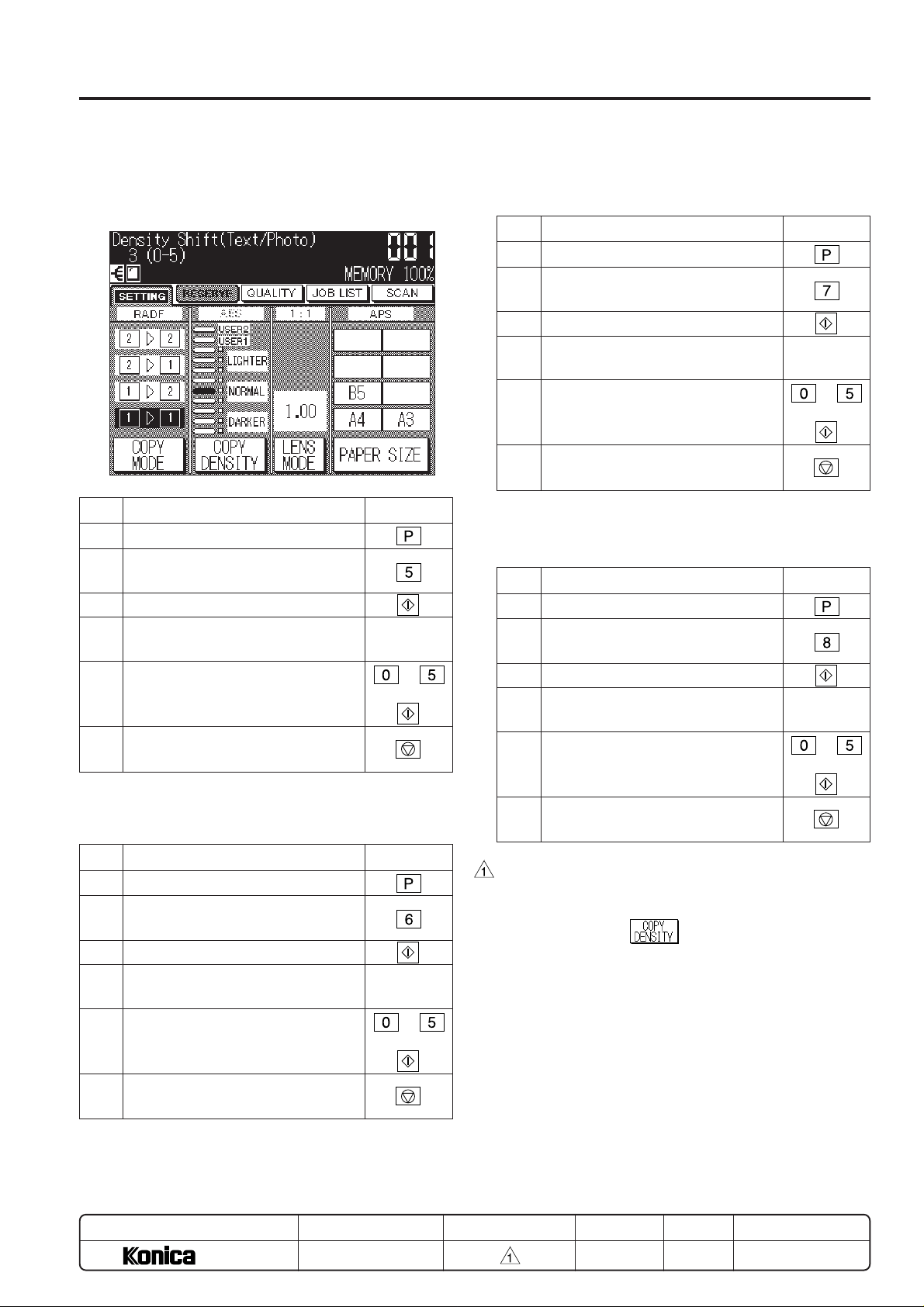
(text/photo) (*1)
[Density Shift (text/photo) Check Screen]
Step Operation procedure
1 Press the P button.
2 Press 5 from the copy quantity setting
button.
3 Press the Start print button.
4 Check the density shift (text/photo)
displayed in the message area.
5 When changing the setting, enter a
value from the copy quantity setting
button and press the Start print button.
6 Press the Stop/Clear button to return
to the basic screen.
Operation
to
+
[8] Checking or Setting the Density Shift
(text) (*1)
[9] Checking or Setting the Density Shift
(photo) (*1)
Step Operation procedure
1 Press the P button.
2 Press 7 from the copy quantity setting
button.
3 Press the Start print button.
4 Check the density shift (photo) dis-
played in the message area.
5 When changing the setting, enter a
value from the copy quantity setting
button and press the Start print button.
6 Press the Stop/Clear button to return
to the basic screen.
Operation
to
+
[10] Checking or Setting the Density Shift
(Increase contrast) (*1)
Step Operation procedure
1 Press the P button.
2 Press 8 from the copy quantity setting
button.
3 Press the Start print button.
4 Check the density shift (Increase con-
trast) displayed in the message area.
5 When changing the setting, enter a
value from the copy quantity setting
button and press the Start print button.
6 Press the Stop/Clear button to return
to the basic screen.
Operation
to
+
Step Operation procedure
1 Press the P button.
2 Press 6 from the copy quantity setting
button.
3 Press the Start print button.
4 Check the density shift (text) displayed
in the message area.
5 When changing the setting, enter a
value from the copy quantity setting
button and press the Start print button.
6 Press the Stop/Clear button to return
to the basic screen.
MODEL
7040
SERVICE HANDBOOK
Operation
to
+
REVISED EDITIONMANUAL
• Setting value can be set each mode individually.
• Decreasing the setting value darken the copy density.
• When changing the setting value, all density area that
can be set with the
• Decreasing the setting value (copy density is darker) increase the toner consumption for one copy.
5 - 5
DATE
MAR. 1998
key is changed.
PAGE
5-5
REPLACEMENT
METHOD
Page 7
ADJUSTMENT 25
25 MODE
[1] Setting Method
A special operating mode called “25 Mode” has been provided
with this machine. This mode enables rewriting of the nonvolatile storage and specify other various settings.
1. Turn OFF the SW2 (sub power) when the SW1 (main
power) remains ON.
2. Turn the SW2 (sub power) ON while pressing 2 and 5 of
the copy quantity setting buttons. The 25 mode menu
screen will appear.
In the 25 mode normal copy operation becomes unavailable.
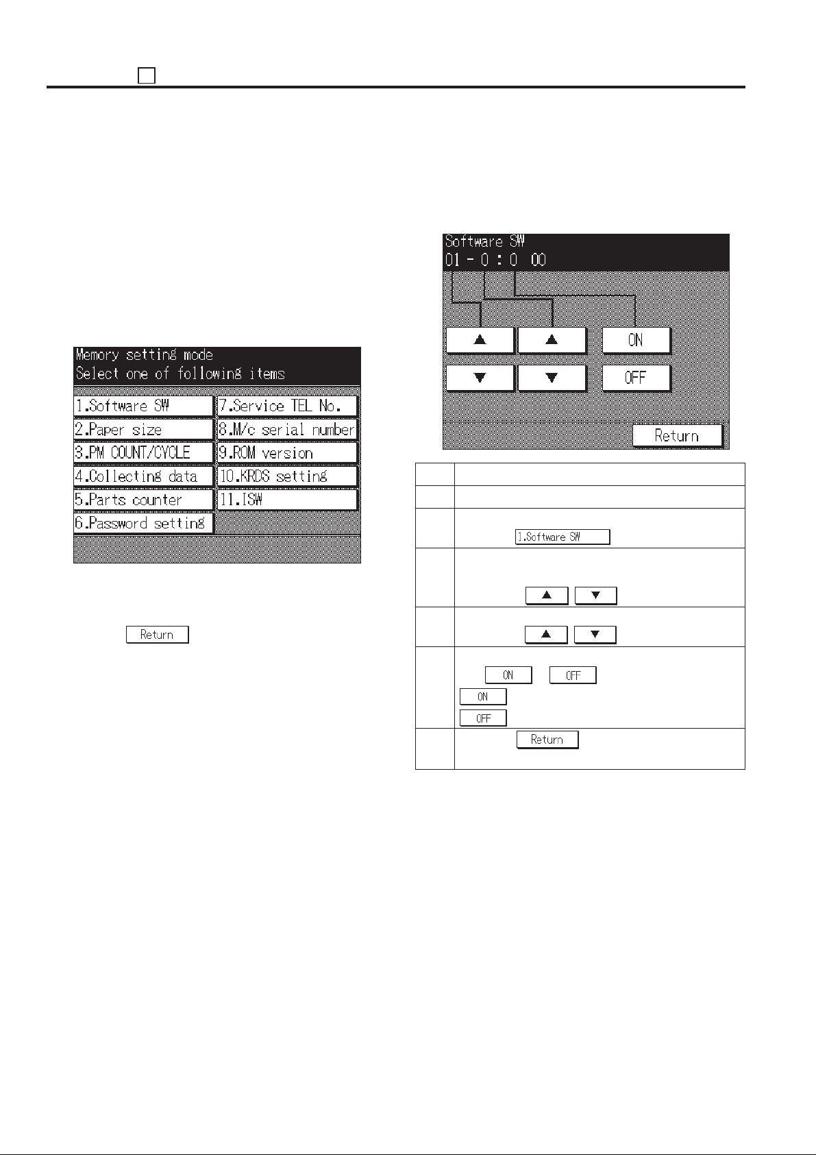
[25 MODE MENU SCREEN]
3. Press the desired item key on the LCD screen.
Each setting screen will appear.
4. Enter data in each selected screen.
5. Press the
entered.
6. Turn the SW2 (sub power) off to cancel the 25 mode.
7. New data will be effective after restarting.
key to check the data that has been
[2] Setting Software DIP SW
1. Setting method
This setting specifies the software DIP switch on the software
SW setting screen. (*1)
[Software SW setting screen]
Step Operation procedure
1 Enter the 25 mode.
2 [25 Mode Menu Screen]
Press the key.
3 [Software SW setting screen]
Select DIP switch number.
Use the left , key.
4 Select bit number of the DIP switch.
Use middle , key.
5 Select ON (=1) or OFF (=0) of the DIP switch.
Use or key.
: Set bit.
: Clear bit.
6 Press the key to return to the 25 mode
menu screen.
5 - 6
Page 8
*1:
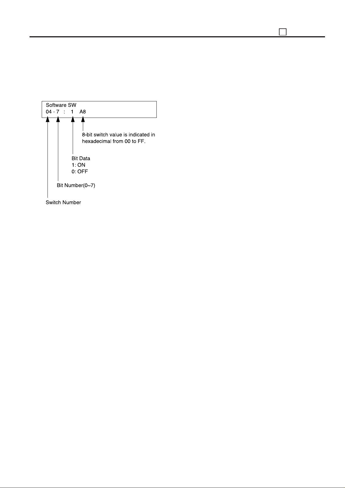
• The bit of the DIP switch is written in the non-volatile RAM
every time it is changed.
• The numbers shown in the message area are defined as
follows:
25 ADJUSTMENT
For each switch function, refer to “List of Software SW”.
5 - 7
Page 9
ADJUSTMENT 25
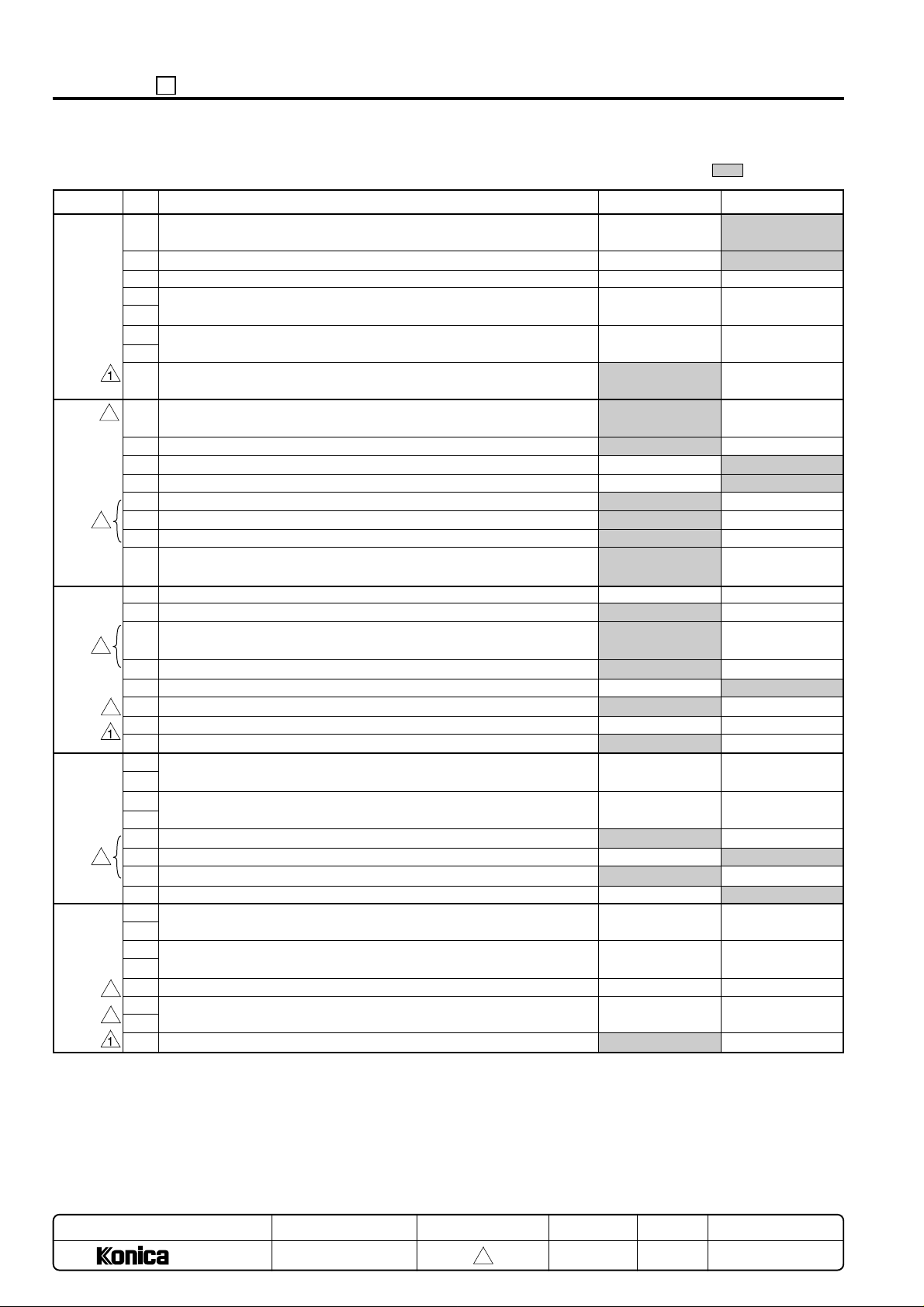
<List of Software SW> : Default value
DIPSW No.
DIPSW1
3
DIPSW2
3
3
DIPSW3
3
DIPSW4
3
DIPSW5
3
3
BIT
Operation when key counter is removed
0
A3 (11x17) count method
1
Function
2
Selection of maximum number of copies that can be stapled by FS-105
3
(for plain paper)
4
Selection of maximum number of copies that can be stapled by FS-105
5
(for thick paper)
6
Limitation of the number of the stapled copies set
7
Toner out halt condition 1
0
1
2
3
Folded original mode
4
Message for staple automatic release (1 shot) indication
5
Prohibit rotation key indication
6
Prohibition of non-image area erases, repeat (auto) and original posi-
7
tion correction
0
F34/F35/F36 latch
1
Toner out halt condition 2
2
EKC password image restore period for copy reservation.
3
4
By-pass feed non-standard size selection.
5
6
7
Toner level detection (“Supply toner” indication)
0
1
Number of copies allowed before machine stops after “Supply Toner”
2
indication.
3
Reserve list priority, delete key indication.
4
Prohibition of copy operation at low toner detection
5
Copy reservation for coin vendor use.
6
Image quality screen OK key display
7
Destination switchover
0
1
F4 size setting
2
3
RADF 8.5 x 11 size detection (At PS303 detection)
4
5
Fixing control temperature change.
6
Halftone fixing remedy (When the machine is not turned on for a long period.)
7
0
Ignore
Count as 1
*1
*2
No limit
Priory to DIP SW3-2
Do not change
Do not use
Do not use
No
Yes
No
No
No
When job completed
Normal
Do not use
No
Do not change
*3
*4
Display
No
Possible (Enabled)
Yes
*5
*6
8.5x11
*21
No
1
Instantaneous
stop jam
Count as 2
*1
*2
Temporary stop at
25 set
Immediately halts
after exiting paper
Do not use
Do not change
Do not change
Yes
No
Yes
Yes
Yes
At where number
of copies end
Immediately resumes
Do not change
Yes
Do not use
*3
*4
No Display
Yes
Not possible (Disabled)
No
*5
*6
11x17
*21
Yes
MODEL
7040
MANUAL
SERVICE HANDBOOK
REVISED EDITION
5 - 8
3
DATE
Mar. 1999
PAGE
5-8
METHOD
REPLACEMENT
Page 10
25 ADJUSTMENT
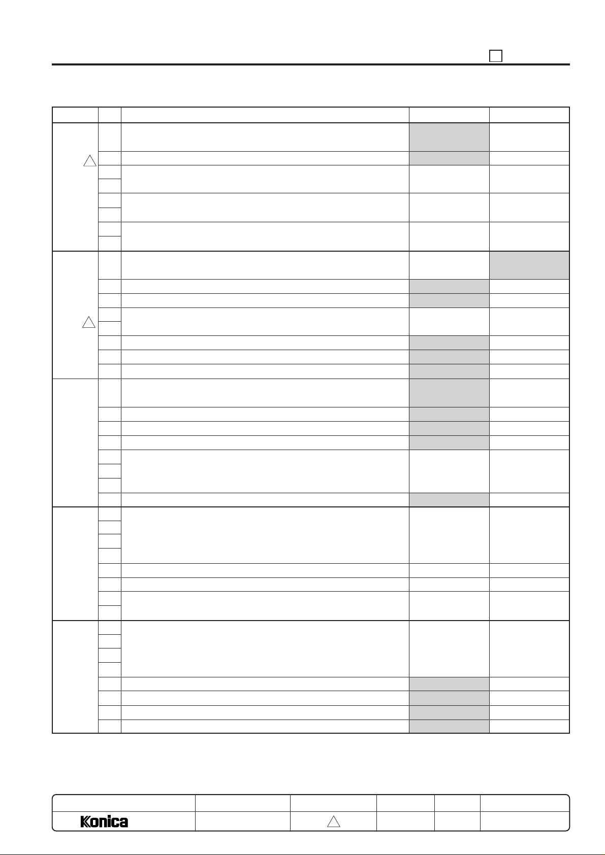
DIPSW No.
3
DIPSW6
DIPSW7
3
DIPSW8
DIPSW9
DIPSW10
BIT
0
Prevention of image faulty at high temperature and high humidity.
(When the machine is not turned on for a long period.)
1
K size selection (for Taiwan)
2
Paper feed control for thick paper
3
4
Polygon motor low speed rotation timing
5
6
Polygon motor low speed rotation selection
7
0
Judging of Image erase area
1
Selection of auto restart when paper is replenished.
2
8.5x11 APS (Japan, Europe), A4 APS (U.S.A.)
3
Non-standard size original platen APS
4
(When original is set more than 30mm away from scale plate)
5
Password request for 25/36/47 mode (Password: 9272)
6
Selection of A series size (European version)
7
Setting of displaying the full-auto screen
0
Selection of non-image area erase mode
1
Changing of key operator fixed magnification setting
2
Disabling copying when PM count reached.
3
Adjusting of LCD contrast to help screen.
4
Priority tray when APS is released.
5
6
7
Data collection (25 mode)
0
Selection of copy quantity limit
1
2
3
4
5
Message selection for P81
6
7
Setting of weekly timer daylight saving time
0
1
2
3
Selection of magnification mode when APS function is canceled.
4
Selection of setting screen message.
5
Displaying of icon to line 3
6
Displaying of JAM code
7
Function
0
Yes
AB type size
*7
*8
*9
Original size priority
No
Yes
*10
No
No
Yes
Rectangle erasure
Permit
Permit
No
*11
No
*12
*13
*14
Auto mode
Guidance display
No
No
1
No
K size
*7
*8
*9
Paper size priority
Yes
No
*10
Yes
Yes
No
Erasure for obliquely
placed original
Prohibit
Prohibit
Yes
*11
Yes
*12
*13
*14
Life size (1:1)
Machine state display
Yes
Yes
MODEL
7040
MANUAL
SERVICE HANDBOOK
REVISED EDITION
5 - 9
3
DATE
Mar. 1999
PAGE
5-9
METHOD
REPLACEMENT
Page 11
ADJUSTMENT 25
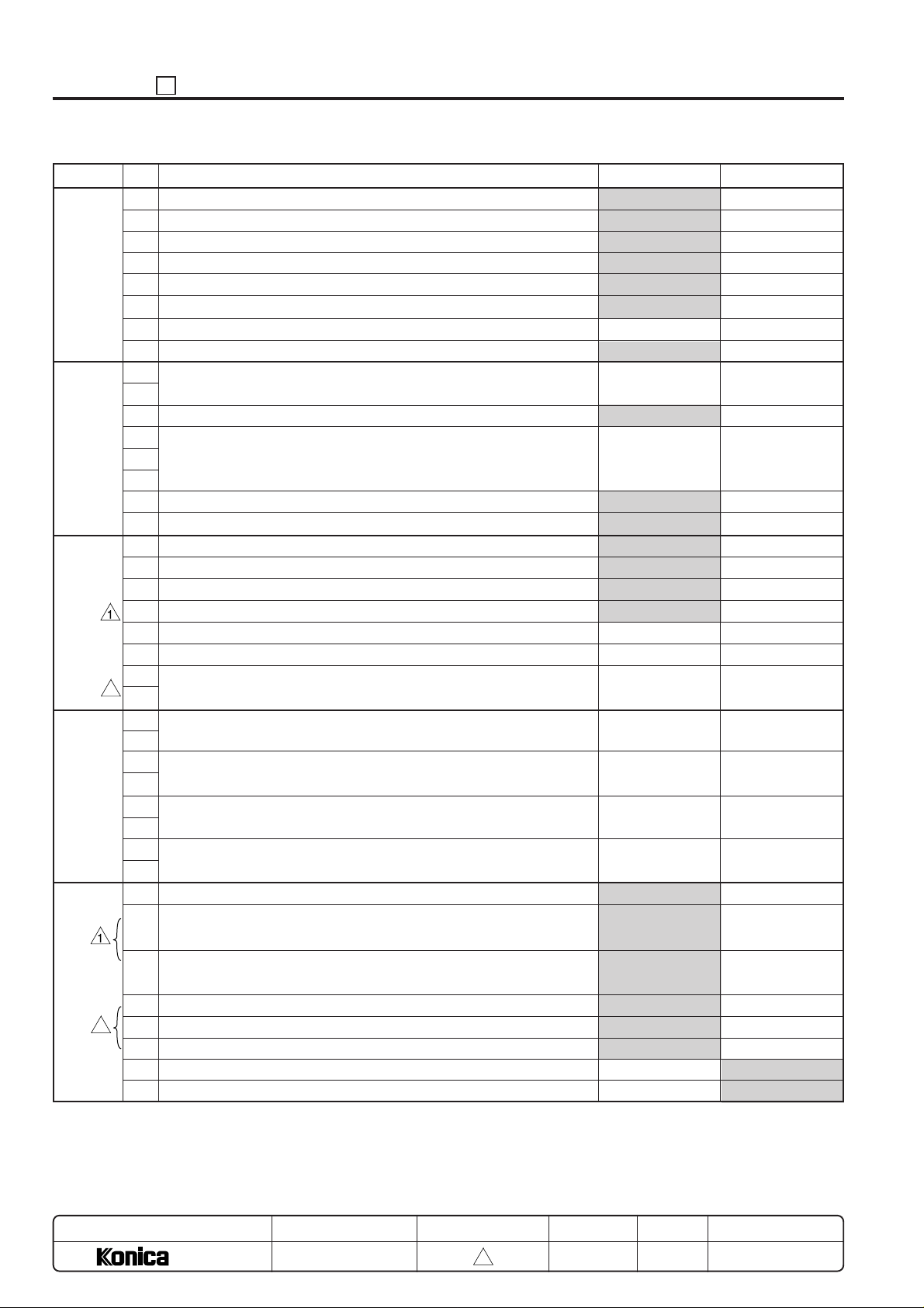
DIPSW No.
DIPSW11
DIPSW12
DIPSW13
3
DIPSW14
DIPSW15
3
BIT
Tray screen OK key display
0
Magnification screen OK key display
1
Density screen OK key display
2
Copy mode screen OK key display
3
No “OK” switchover time
4
5
6
7
Initial copy mode
0
1
Initial image scanning mode
2
Setting of PM count at which copying is inhibited.
3
4
5
KRDS connection recognition
6
F/E screen switchover (except for F34, F35 and F36)
7
0
1
2
Fine line width smoothing filter
3
4
5
Non-original deletion threshold value change.
6
7
Operation when stapling is inhibited. (large size: except for A5R, B5R,
0
5.5x8.5R)
1
Operation when stapling is inhibited. (small size: except for A5R, B5R,
2
5.5x8.5R)
3
Operation without staple clip at an applicable position when the 1-
4
position stapling is selected.
5
Operation without staple clip at an applicable position when the 2-
6
position stapling is selected.
7
0
Waiting the print start at the copy reservation
1
(Countermeasure against paper wrinkling by the fixer).
Waiting the print start other than the copy reservation
2
(Countermeasure against paper wrinkling by the fixer).
Universal tray switch screen.
3
Face up paper exit selection during by-pass feed selection (Tray 1 or no FNS)
4
Universal tray switch screen A type row display.
5
Finisher tray 1 full-stack detection & auto tray switching.
6
Auto tray switching when finisher tray 2/3 full-stack is detected.
7
Function
0
Yes
Yes
Yes
Yes
Short
Do not change
Do not change
*15
RADF
*16
Not connect
No
Do not change
Do not change
Do not change
ON
*22
*17
*18
*19
*20
Do not change
Not waiting
Not waiting
Yes
Yes
Yes
No
No
1
No
No
No
No
Long
Do not use
Do not use
*15
Platen
*16
Connect
Yes
Do not used
Do not used
Do not used
OFF
*22
*17
*18
*19
*20
Do not used
Waiting
Waiting
No (special display)
No
No
Yes
Yes
MODEL
7040
MANUAL
SERVICE HANDBOOK
REVISED EDITION
5 - 10
3
DATE
Mar. 1999
PAGE
5-10
METHOD
REPLACEMENT
Page 12
25 ADJUSTMENT
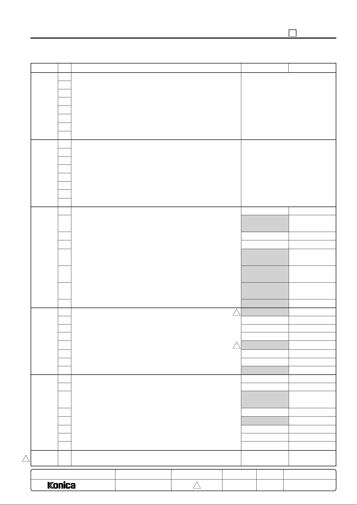
DIPSW No.
DIPSW16
DIPSW17
DIPSW18
DIPSW19
DIPSW20
DIPSW21
3
DIPSW24
BIT
Separation claw ON timing (400 dpi)
0
1
2
3
4
5
6
7
Separation claw OFF timing (400 dpi)
0
1
2
3
4
5
6
7
Unit isolation (1)
0
1
2
3
4
5
6
7
Unit isolation (2)
0
1
2
3
4
5
6
7
Unit isolation (3)
0
1
2
3
4
5
6
7
Preliminaries
~
-
Function
Separation claw ON timing (400 dpi)
Enter setting value by binary number.
Default value: 56 (111000)
Separation claw OFF timing (400 dpi)
Enter setting value by binary number.
Default value: 85 (1010101)
Tray 2 (copier) can
be used.
Tray 3 (DB upper)
can be used.
Tray 4 (DB middle) can be used.
Tray 5 (DB lower)
can be used.
DB can be used.
Printer board can be used
3
ADU can be used
3
RADF can be used.
Finisher tray 2/3
can be used.
Stapler can be used.
0
–
Tray 2 (copier) is
isolated.
Tray 3 (DB upper)
is isolated.
Tray 4 (DB middle) is isolated.
Tray 5 (DB lower)
is isolated.
DB is isolated.
Printer board is isolated
ADU is isolated
RADF is isolated.
Finisher tray 2/3
are isolated.
Stapler is isolated.
–
1
–
–
MODEL
7040
MANUAL
SERVICE HANDBOOK
REVISED EDITION
5 - 11
3
DATE
Mar. 1999
PAGE
5-11
METHOD
REPLACEMENT
Page 13
ADJUSTMENT 25
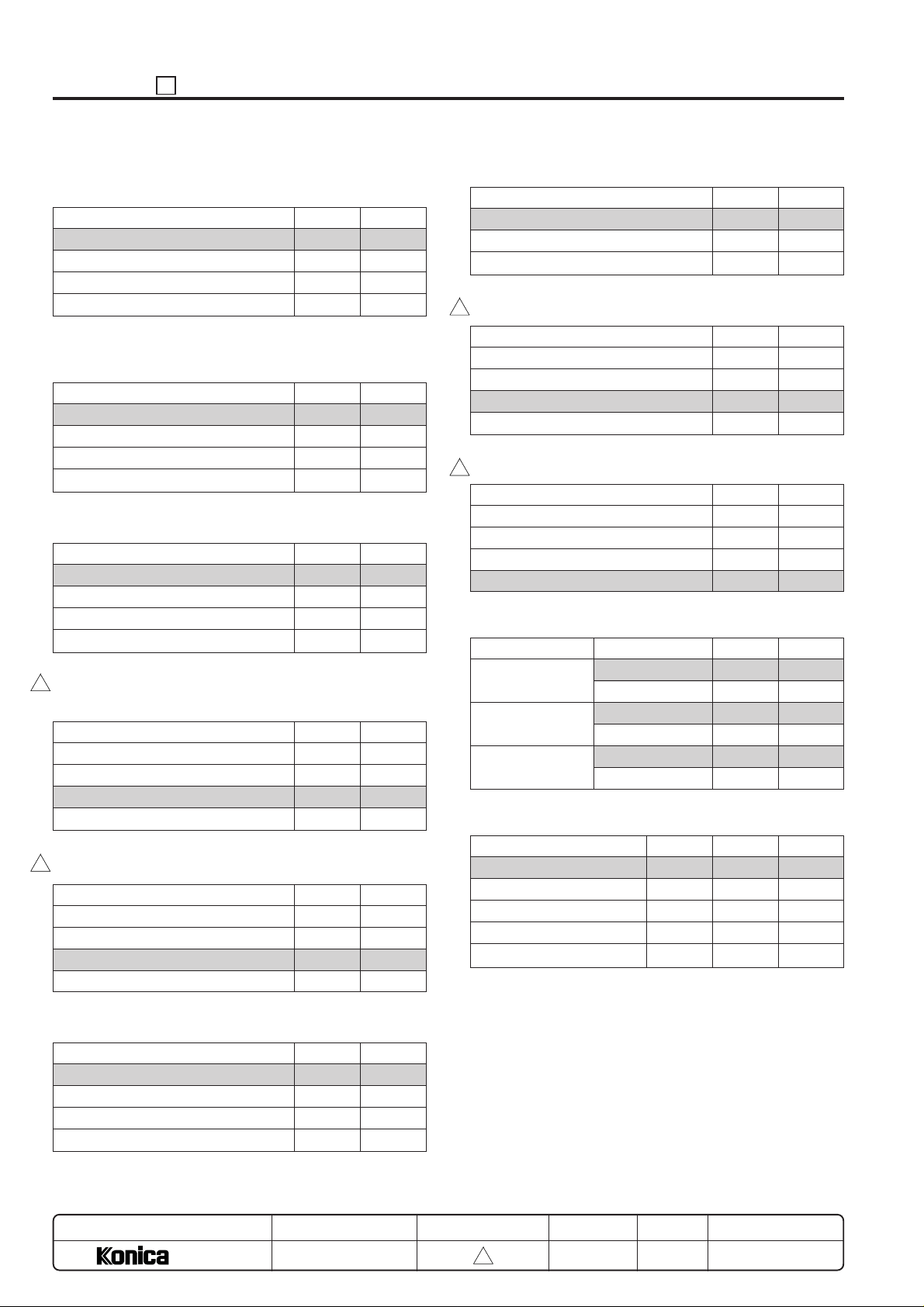
*1: Selection of maximum number of copies that can be
stapled by FS-105 (for plain paper)
Mode
50 copies
45 copies
40 copies
35 copies
*2: Selection of maximum number of copies that can be
stapled by FS-105 (for thick paper)
Mode
20 copies
15 copies
25 copies
10 copies
*3: Toner level detection (“Supply toner” indication)
Mode
After 100 copies
After 1000 copies
After 2000 copies
After 3000 copies
3
*4: Number of copies allowed before machine stops after
“Supply Toner” indication.
Mode
0
1000
2000
3000
3
*5: Destination switchover
Mode
Japan
U.S.A.
Europe
Taiwan
1-4 1-3
00
01
10
11
1-6 1-5
00
01
10
11
4-1 4-0
00
01
10
11
4-3 4-2
00
01
10
11
5-1 5-0
00
01
10
11
*7: Paper feed control for thick paper
Mode
Normal
30 PPM
20 PPM
3
*8: Polygon motor low speed rotation timing
Mode
15 sec after job is completed
30 sec after job is completed
60 sec after job is completed
120 sec after job is completed
*9: Polygon motor low speed rotation selection
3
Mode
Low speed does not take place.
Low speed rotation; 20000 rpm
Stop
400 dpi rotation (33,070.9 rpm)
*10: Non-standard size original platen APS
Mode
Japan
U.S.A.
Europe
*11: Priority tray when APS is released
Mode
No preference
Lower tray; main body
DB1
DB2
DB3
Size
B5R
B6R
5.5 x 8.5R
8.5 x 11
B5R
A5R
8-6 8-5 8-4
000
010
011
100
101
6-3 6-2
00
01
10
6-5 6-4
00
01
10
11
6-7 6-6
00
01
10
11
7-4 7-3
00
10
00
01
00
10
*6: F4 size setting
Mode
8.5 x 13 (216 x 330)
8.25 x 13 (210 x 330)
8.125 x 13 (206 x 330)
8 x 13 (203 x 330)
MODEL
7040
5-3 5-2
00
01
10
11
MANUAL
SERVICE HANDBOOK
REVISED EDITION
5 - 12
3
DATE
Mar. 1999
PAGE
5-12
METHOD
REPLACEMENT
Page 14
25 ADJUSTMENT
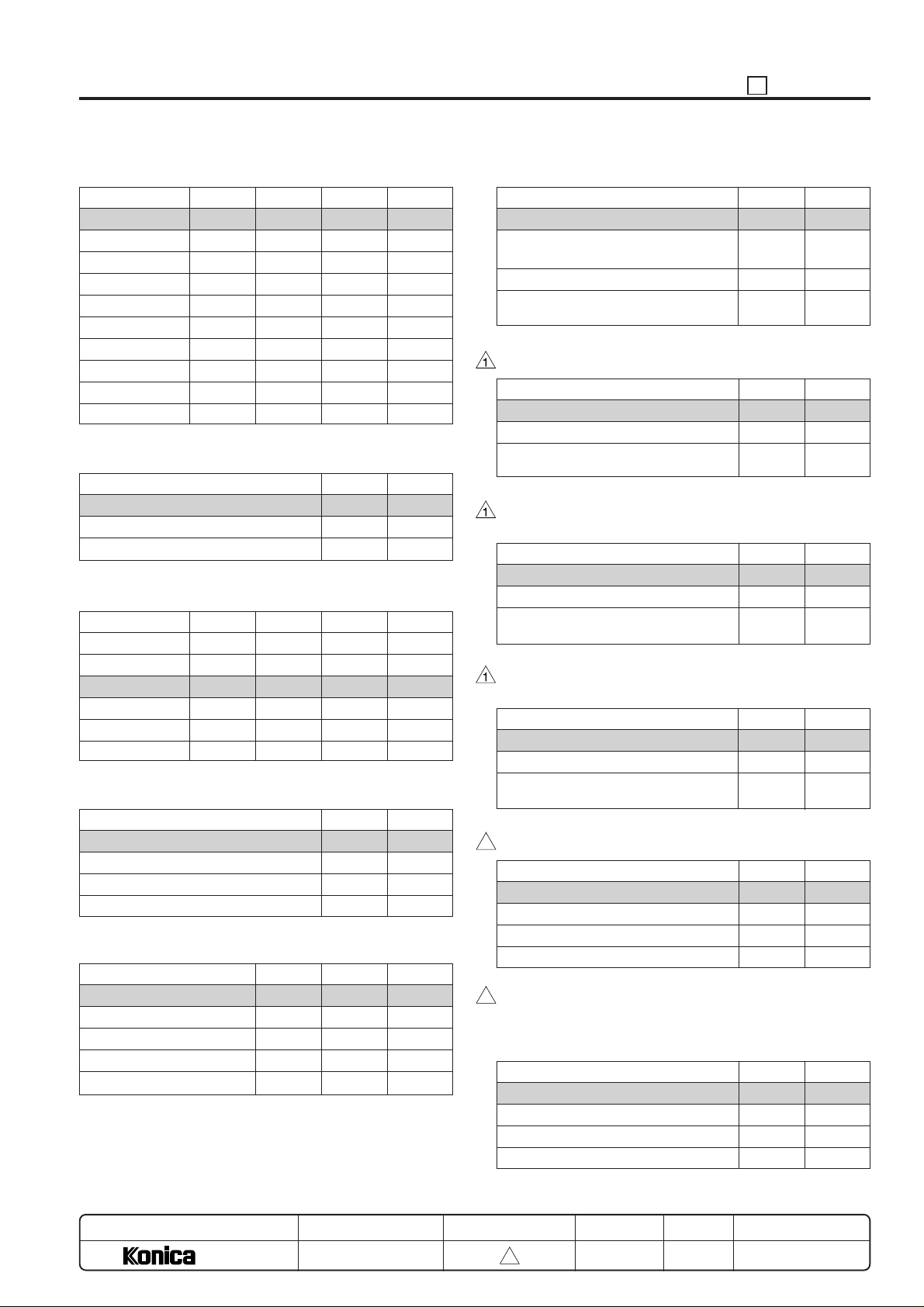
*12: Selection of copy quantity limit
Mode
Unlimited
1
3
5
9
10
20
30
50
99
*13: Message selection for P81
Set the key counter
Set the copy card
Insert a coin
*14: Setting of weekly timer daylight saving time
Mode
0 minutes
30 minutes
60 minutes
90 minutes
120 minutes
150 minutes
*15: Initial copy mode
*16: Setting of PM count at which copying is inhibited.
Mode
1000 copies
2000 copies
3000 copies
4000 copies
5000 copies
9-3 9-2 9-1 9-0
0000
0001
0010
0011
0100
0101
0110
0111
1000
1001
Mode
10-3 10-2 10-1 10-0
0000
0011
0110
1001
1100
1111
Mode
1-1
1-2
2-1
2-2
12-5 12-4 12-3
000
001
010
011
100
9-7 9-6
00
01
10
12-1 12-0
00
01
10
11
*17: Operation when stapling is inhibited. (large size)
Mode
Auto cancel
Auto switching to 1-position stapling
mode
Inhibit
Forced 2-position stapling mode operation
*18: Operation when stapling is inhibited. (small size)
Mode
Auto cancel
Inhibit
Forced 1-position stapling mode operation
*19: Operation without staple clip at an applicable position
when the 1-position stapling is selected.
Mode
Auto cancel
Inhibit
Forced 1-position stapling mode operation
*20: Operation without staple clip at an applicable position
when the 2-position stapling is selected.
Mode
Auto cancel
Inhibit
Forced 2-position stapling mode operation
*21: Fixing control temperature change
3
Mode
Normal control
+10°C
–10°C
Normal control
3
*22: Non-original deletion threshold value change.
Caution: Denser originals will be easier to detect as the
threshold value becomes smaller, however it will be
more susceptible to detection error from stray light.
Mode
Threshold value 80h
Threshold value 60h
Threshold value 50h
Threshold value 50h
14-1 14-0
00
01
10
11
14-3 14-2
00
10
11
14-5 14-4
00
10
11
14-7 14-6
00
10
11
5-6 5-5
00
01
10
11
13-7 13-6
00
01
10
11
MODEL
7040
MANUAL
SERVICE HANDBOOK
REVISED EDITION
5 - 13
3
DATE
Mar. 1999
PAGE
5-13
METHOD
REPLACEMENT
Page 15
ADJUSTMENT 25
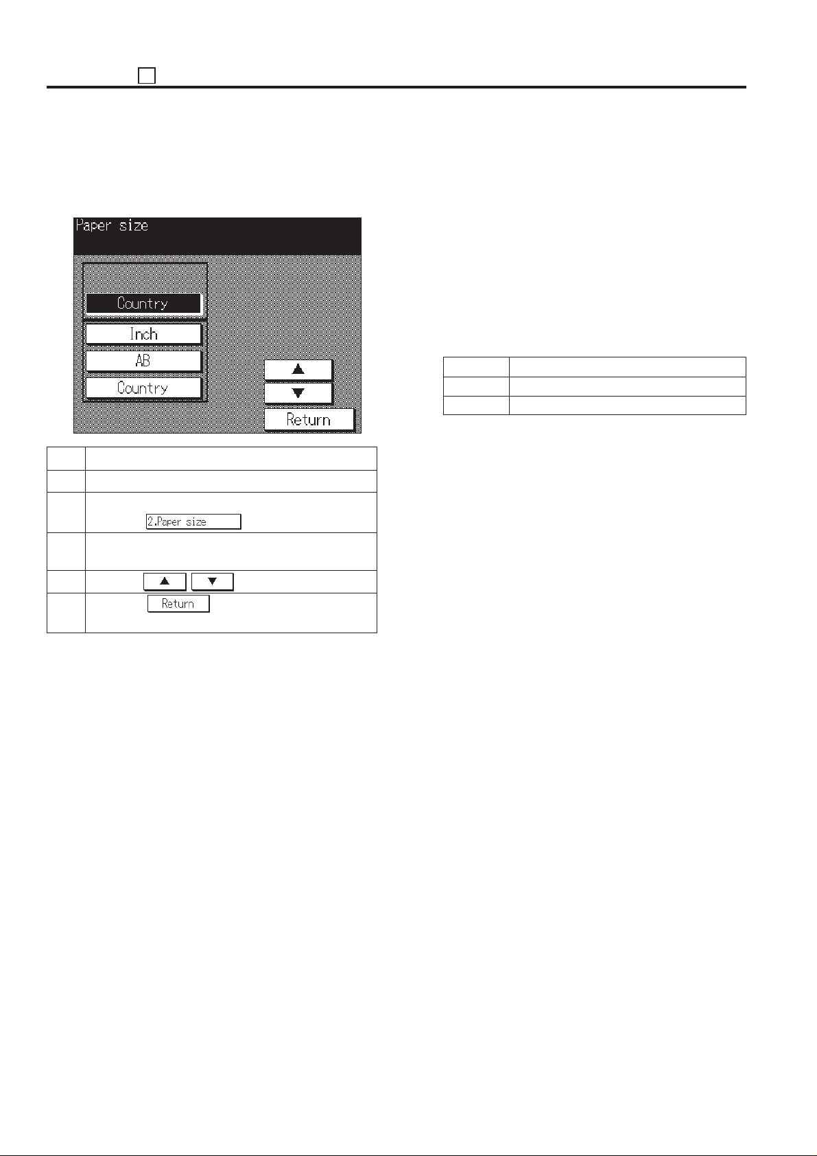
[3] Tray Size Setting
This function stores the paper size in the memory of the main
body if it has been changed .
[Tray size setting screen]
Step Operation procedure
1 Enter the 25 mode.
2 [25 Mode Menu Screen]
Press the
3 [ Tray size setting screen ]
Press the tray key to be changed.
4 Press the , key to select a paper size.
5 Press the key to return to the 25 mode
menu screen.
key.
Reference:
• Since the upper tray of the main body is the ADU, the
selection message is not displayed.
• When the DB-208 or DB-608 is not installed, the trays
of the DB section is not displayed.
• Availability of paper size depends on the selected
tray. The unavailable paper sizes will be skipped and
not displayed.
• New data on tray size will be written in non-volatile
RAM every time it is changed in this screen.
• The following table shows the paper sizes that can be
used in the LCT (DB-608).
Japan A4, A4R, B5, B5R, 8.5 x 11, 8.5 x 11R
Europe A4, A4R, B5, B5R, 8.5 x 11, 8.5 x 11R
U.S.A. 8.5 x 11, 8.5 x 11R, A4, A4R
Caution:
• The main body tray, all trays in the DB-208, the upper
tray of the DB-608 and the by-pass tray can not be
adjusted in the Non-volatile RAM. These trays detect
paper size via sensors.
• The size series of the universal tray can be selected
as follows.
· Destination setting
· AB series
· Inch series
• The screen is automatically changed from the optional
tray according to the type of trays.
5 - 14
Page 16
25 ADJUSTMENT
[4] PM Count Setting
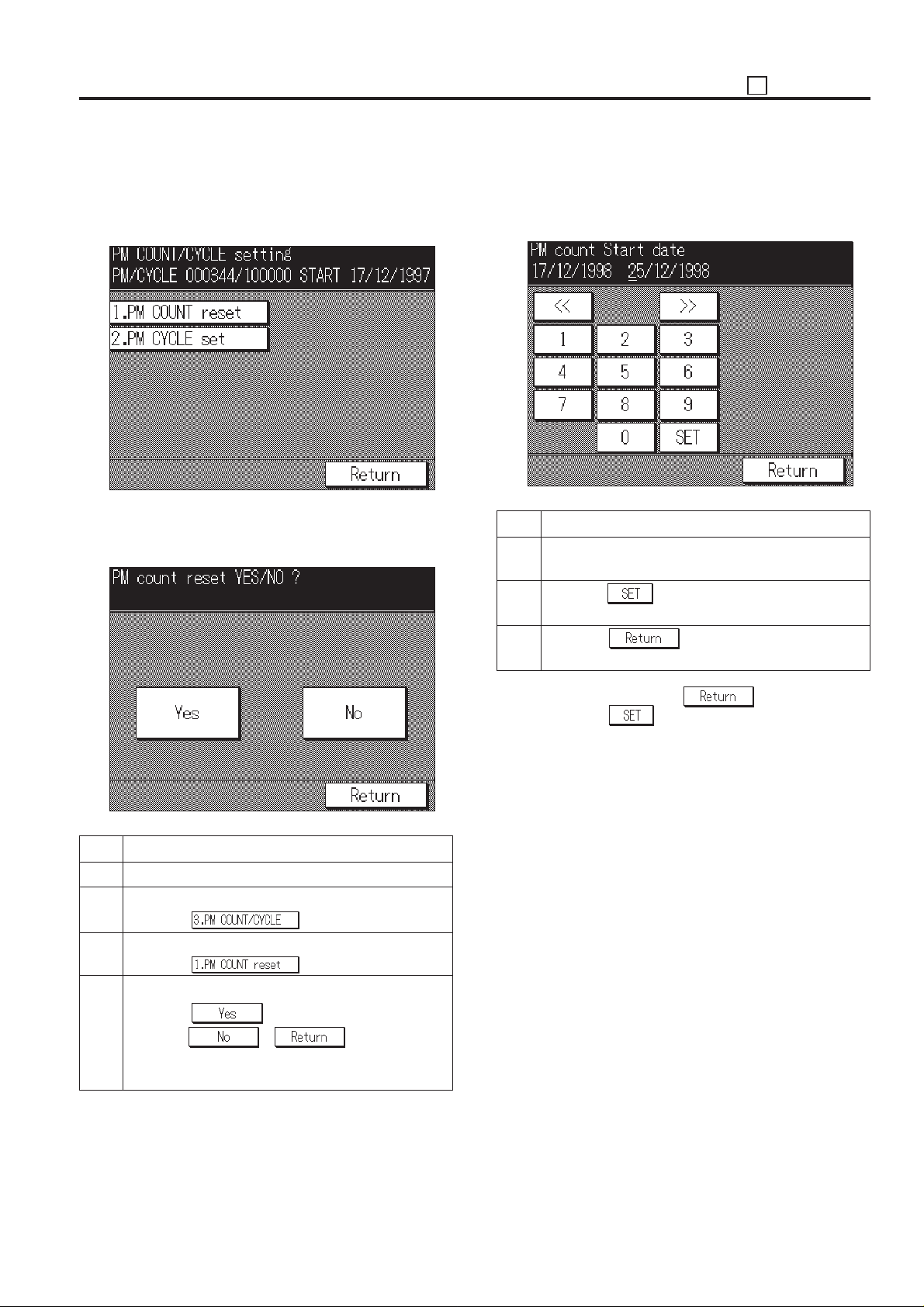
This function resets the PM count and sets the PM cycle.
Care should be taken to reset the PM count properly.
[PM Count/Cycle setting menu screen]
1. PM count reset
Select whether to reset the count in the PM count reset screen.
[PM count reset screen]
2. Entering PM Count Start date
When resetting the PM count, it is necessary to input the start
date, and the screen below will appear automatically.
[PM Count Start date entering screen]
Step Operation procedure
1 [PM Count Start date entering screen]
Enter a PM count start date from the numeric key.
2 Press the
entered.
3 Press the key to return to the PM count/
cycle menu screen.
key to enter the data that has been
Step Operation procedure
1 Enter the 25 mode.
2 [25 Mode Menu Screen]
Press the
3 [PM Count/Cycle Setting Menu Screen]
Press the key.
4 [PM count reset screen]
Press the key to reset the PM count.
Press the
count is not reset and to return to the PM count/cycle
setting menu screen.
key.
or key, then the PM
Caution: When pressing the key without press-
ing the
changed. It is necessary to reset the count again for
inputting the count.
key, the PM count start date is not
5 - 15
Page 17
ADJUSTMENT 25
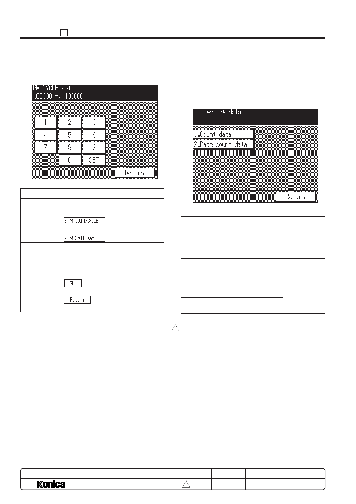
3. Setting PM cycle
This function sets the PM cycle.
[PM Cycle Setting Screen]
Step Operation procedure
1 Enter the 25 mode.
2 [25 Mode Menu Screen]
Press the
3 [PM Count/Cycle Setting Menu Screen]
Press the key.
4 [PM Cycle Setting Screen]
Enter PM cycle from the numeric key.
Enter upper 3-digit (hundred thousand, ten thou-
sand, thousand) only.
5 Press the
been entered.
6 Press the
cycle setting menu screen.
key to enter a PM cycle that has
key.
key to return to the PM count/
[5] Data Collection
This function enables viewing of the various data recorded in
the machine.
Also, it is possible for the collected data to be checked by KRDS
and management listing.
[Data collection menu screen]
<Data collection list>
Classification
Data collection 1
Data collection 2
Data collection 3
Data collection 4
Contents
Count number of copies by each size
Count RADF original
feed quantities
Count number of JAM
occurrence by each
point
Count number of copies by each mode
Count number of SC
occurrence
Pre-operation
– (*1)
Enter the 25
mode.
Select [1. Software SW].
Set the address
to 8-7:1 (*2)
MODEL
7040
MANUAL
SERVICE HANDBOOK
*1: Only data collection 1 can be checked in default.
*2: The setting is 25 mode, Dip-SW 8-7 to “1”.
3
REVISED EDITION
5 - 16
3
DATE
Mar. 1999
PAGE
5-16
METHOD
REPLACEMENT
Page 18
25 ADJUSTMENT
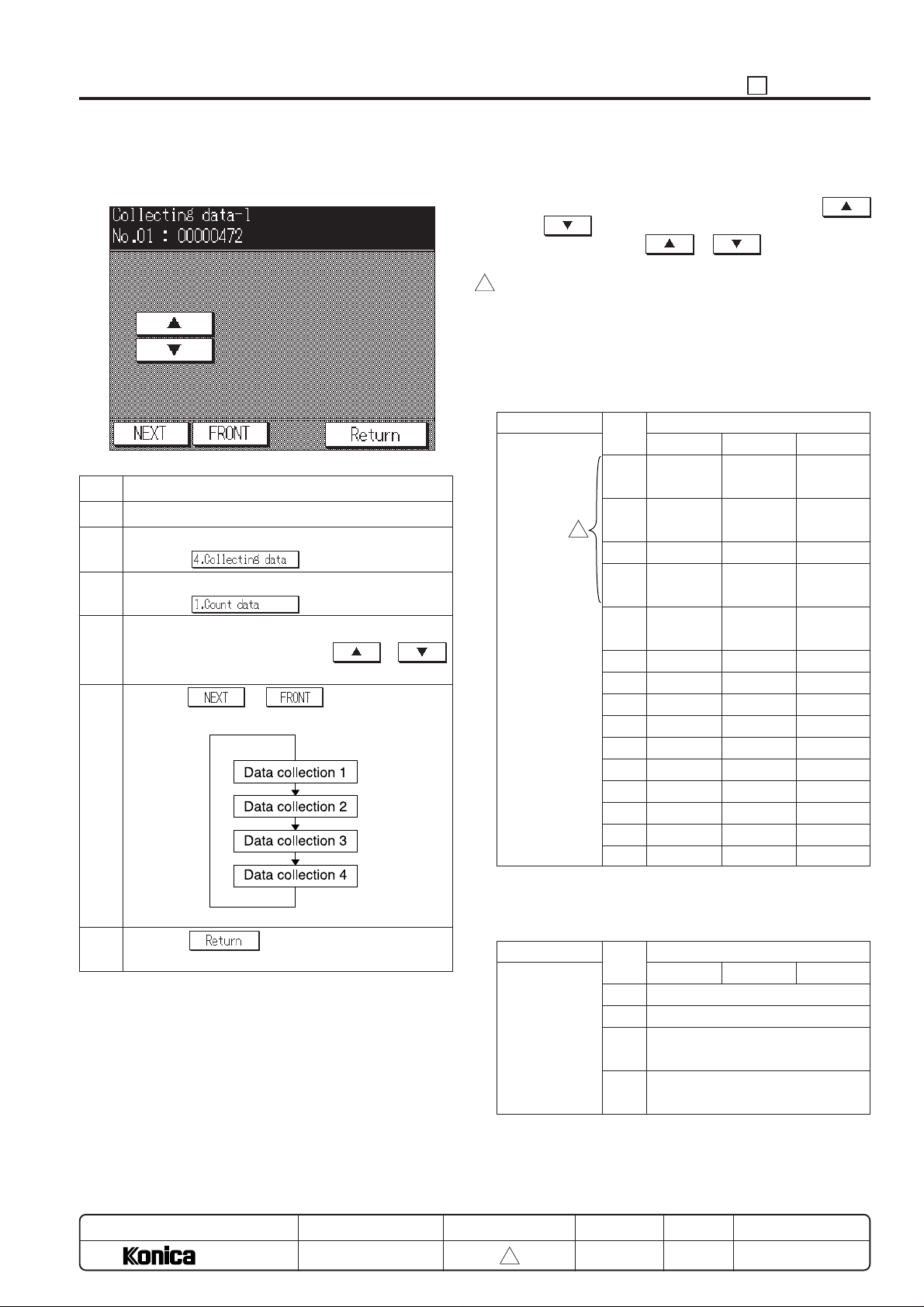
1. Operation procedure
[Data collection screen]
Step Operation procedure
1 Enter the 25 mode.
2 [25 Mode Menu Screen]
Press the key.
3 [Data collection menu screen]
Press the key.
4 [Data collection screen]
Change the data number with the
key.
5 Pressing or key enables to dis-
play next data collection screen. (*3)
or
(1) The data is displayed at the line 2 in the message display
area as “Data number (No.): Count value (000000)”.
(2) The data number can be changed by pressing the
or key.
(3) Press and hold the
next items continuously.
*3: In order to confirm collected data 2 to 4, set Dip-SW 8-7
3
to “1” beforehand.
or key to display the
2. Data collection details
(1) Data collection 1
a. Count number of copies by each size
Type
Count number
of copies by
each size
Size Paper size for destination
No. Japan Europe U.S.A
1 A4+A4R A4+A4R 8.5 x 11
2 B5+B5R B5+B5R 5.5 x 8.5
3
3 A5+A5R A5+A5R –
4 8.5 x 11 – –
+8.5 x 11R
5 AB series AB series Inch series
Special Special Special
6 A3R A3R 11 x 17R
7 A4R A4R 8.5 x 14R
8 A5R A5R 8.5 x 11R
9 B4R B4R 5.5 x 8.5R
10 B5R B5R –
11 B6R F4R –
12 Post card – –
13 – – –
14 8.5 x 11R – –
15 – – –
+8.5 x 11R
+5.5 x 8.5R
6 Press the key to return to the data collec-
tion menu screen.
MODEL
7040
MANUAL
SERVICE HANDBOOK
b. Count RADF original feed quantities
Type
Count RADF
original feed
quantities
REVISED EDITION
5 - 17
3
Maximum count number: 999,999
Size Paper size for destination
No. Japan U.S.A Europe
16 ADF mode original feed counter
17 RADF mode original feed counter
18 ADF mixed original mode original
feed counter
19 RADF mixed original mode
original feed counter
Maximum count number: 999,999
DATE
Mar. 1999
PAGE
5-17
METHOD
REPLACEMENT
Page 19
ADJUSTMENT 25
(2) Data collection 2
Count number of JAM occurrence by each point
No. Jam Point
1 10-0 By-pass
2 11-0 –
3 12-0 Tray (main body)
4 13-0 DB upper tray
5 14-0 DB middle tray or LCT
6 15-0 DB lower tray
7 16-0 Paper feed jam
8– –
9– –
10 – –
11 30-0 Conveyance jam
12 31-0 Conveyance jam
13 – –
14 – –
15 32-0 Conveyance jam
16 33-0 Conveyance jam
17 34-1 Conveyance jam
18 34-2 Conveyance jam
19 34-3 Conveyance jam
20 34-4 Conveyance jam
21 34-5 Conveyance jam
22 97-1 Conveyance jam
23 92-0 Conveyance jam
24 – –
25 – –
26 61-0 DF-311
27 61-1 DF-311
28 62-0 DF-311
29 62-1 DF-311
30 62-2 DF-311
31 62-3 DF-311
32 62-4 DF-311
33 62-5 DF-311
34 63-0 DF-311
35 63-1 DF-311
36 63-2 DF-311
37 63-3 DF-311
38 63-4 DF-311
39 63-5 DF-311
40 63-6 DF-311
41 63-7 DF-311
42 72-10 FS-105
43 72-11 FS-105
No. Jam Point
44 72-12 FS-105
45 72-13 FS-105
46 72-14 FS-105
47 72-15 FS-105
48 72-16 FS-105
49 – –
50 – –
Maximum count number: 999,999
(3) Data collection 3
Count number of copies by each mode
No. Contents
1 Platen 1-1 mode
2–
3 ADF 2-1 mode
4 ADF 2-2 mode
5 ADF 1-1 mode
6 ADF 1-2 mode
7 Finisher (Staple mode)
8 Finisher (Sort mode)
9 Finisher (Group mode)
10 Finisher (No. of stapling)
11 1.0 magnification mode
12 Fixed ratio (E3: 1.41/2.00)
13 Fixed ratio (E2: 1.22/1.55)
14 Fixed ratio (E1: 1.15/1.29)
15 Fixed ratio (R1: 0.86/0.77)
16 Fixed ratio (R2: 0.82/0.65)
17 Fixed ratio (R3: 0.71/0.50)
18 Arbitrary magnification
19 Zoom
20 2.00 magnification
21 0.45 magnification
22 AMS mode
23 APS mode
24 AE mode
25 Interrupt mode
26 By-pass feed mode
27 Book copy mode
28 Frame erase mode
29 Fold erase mode
30 1.0 image shift mode
31 Reduction image shift mode
32 Thick paper
33 Thin paper
5 - 18
Page 20
25 ADJUSTMENT
No. Contents
34 No. of paper feed quantities at inter-sheet mode
35 –
36 No. of paper feed quantities at OHP mode
37 No. of paper feed quantities at mixed original mode
38 Access number of the Job memory call mode
(Number of pressing the P button)
39 Pre-heat mode
40 Copy quantity is set to 1.
41 Copy quantity is set between 2 and 5.
42 Copy quantity is set between 6 and 10.
43 Copy quantity is set to 11 or above.
44 Inter-sheet
45 –
46 Photo mode
47 –
48 Verti./Horiz. zoom mode
49 Book memory mode
50 Single step mode
51 Text/Photo mode
52 Text mode
53 Arbitrary density mode
54 No. of paper feed quantities at OHP mode 2
55 No. of paper feed quantities at inter-sheet and thick
paper mode
56 –
57 Image insert mode
58 Chapter management mode
59 Combination mode
60 Repeat mode
61 Reverse image mode
62 Non-image area erase mode
63 Increase contrast mode
64 Auto layout copy
65 Face up output
66 Rotation sort
67 –
68 Copy quantity of paper feed from tray 2
69 Copy quantity of paper feed from tray 3
70 Copy quantity of paper feed from tray 4
71 Copy quantity of paper feed from tray 5
72 Copy quantity of paper feed from tray 6
73 Finisher, Number of stapling (front)
74 Finisher, Number of stapling (rear)
75 Number of copies for booklet mode copy
3
Maximum count number: 99,999,999
(4) Data collection 4
Count number of SC occurrence (F code)
Error code
No. (decimal number)
Main code Sub code
1 10-1
2 10-2
3 10-3
4 18-1
5 18-2
6 18-3
7 18-4
8 18-5
9 26-0
3
10 28-1
11 28-2
12 28-3
13 34-1
14 34-2
15 34-3
16 34-4
17 35-1
18 35-2
19 36-1
20 36-2
21 40-0
22 41-1
23 46-0
24 46-8
25 46-10
26 46-11
27 49-2
28 49-4
29 49-6
30 51-2
31 51-3
32 51-4
33 51-5
34 51-6
35 51-7
36 52-1
37 52-2
38 52-3
39 52-4
Classification
Communication abnormality
Paper feed lifting abnormality
High voltage power
source abnormality
Fixing high temperature
abnormality
Fixing low temperature
abnormality
Broken fixing sensor
Optics system abnormality
Image processing abnormality
Motor speed abnormality
Fan lock abnormality
MODEL
7040
MANUAL
SERVICE HANDBOOK
REVISED EDITION
5 - 19
3
DATE
Mar. 1999
PAGE
5-19
METHOD
REPLACEMENT
Page 21
ADJUSTMENT 25
Error code
No. (decimal number)
Main code Sub code
40 56-1
41 56-2
42 56-3
43 56-4
44 56-5
45 56-6
46 56-7
47 56-8
48 56-9
49 56-10
50 60-0
51 67-1
52 67-2
53 67-3
54 70-0
55 77-1
56 77-2
57 77-3
58 77-4
59 77-5
60 77-6
61 77-7
62 77-8
63 77-9
64 77-10
65 77-21
66 77-22
67 77-30
68 80-1
69 80-2
70 80-3
71 80-4
72 80-5
73 81-1
74 81-2
75 88-0
76 89-1
77 89-2
78 89-3
79 89-4
80 89-5
81 89-6
Classification
Image control communication abnormality
Operation control section system error
RADF abnormality
Finisher abnormality
Non-volatile memory
abnormality
Flash ROM abnormality
Image processing abnormality
Control board communication abnormality
Error code
No. (decimal number)
Main code Sub code
82 56-11
83 87-0
3
84 52-5
3
Maximum count number: 9,999
Classification
Control abnormality
Print controller transmission abnormality
Fan lock abnormality
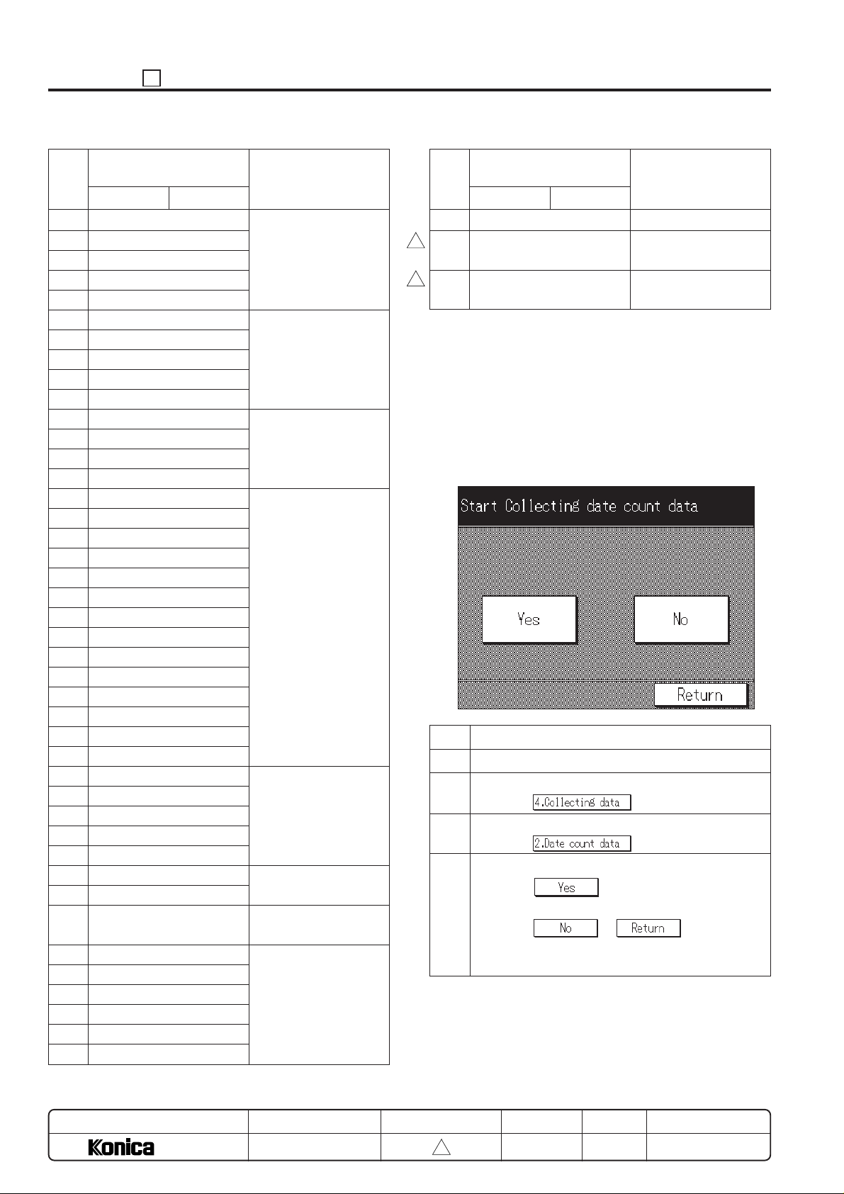
3. Starting Periodic Date Collection
Reset the periodic data from the setting periodic collection start
date. Make a date that this operation is performed as a new
periodic collection start date. The periodic data can be checked
with the KRDS and management list.
[Starting periodic date collection screen]
Step Operation procedure
1 Enter the 25 mode.
2 [25 Mode Menu Screen]
Press the key.
3 [Data collection menu screen]
Press the key.
4 [Starting periodic date collection screen]
Press the
collection.
Press the or key, then data
collection start date is not reset and return to the data
collection menu screen.
key to start the periodic data
MODEL
7040
MANUAL
SERVICE HANDBOOK
REVISED EDITION
5 - 20
3
DATE
Mar. 1999
PAGE
5-20
METHOD
REPLACEMENT
Page 22
25 ADJUSTMENT
[6] Parts counter
Perform the copy count display, count clear, limit value setting
and arbitrarily parts to be replaced setting to the data of the
parts to be replaced (fixed/arbitrarily).
[Parts counter menu screen]
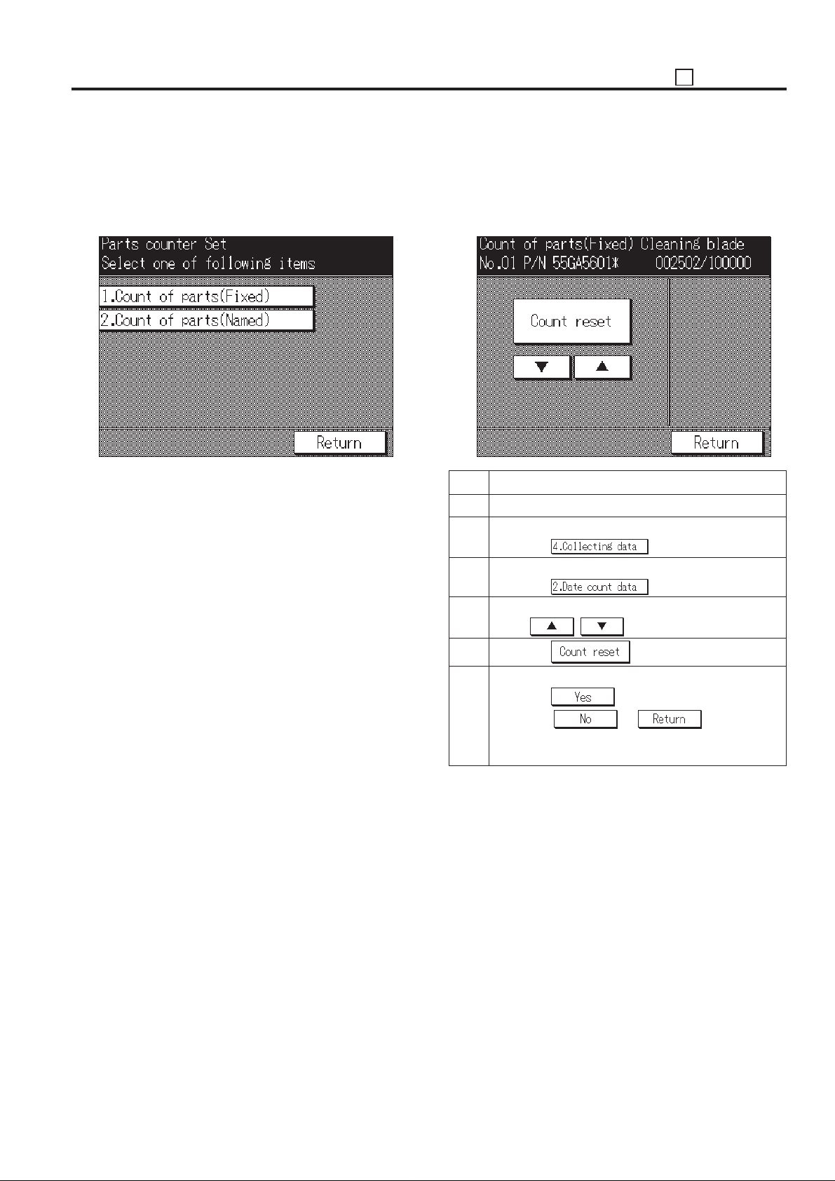
1. Copy count display and count reset by parts to
be replaced (fixed)
Set the parts name of the fixed parts to be replaced (Fixed),
parts No. and copy count display, and count reset.
[Copy count screen by parts to be replaced (Fixed)]
Step Operation procedure
1 Enter the 25 mode.
2 [25 Mode Menu Screen]
Press the key.
3 [Parts Counter Menu Screen]
Press the key.
4 [Copy count screen by parts to be replaced (Fixed)]
Press , key to select the data.
5 Press the key.
6 [Count reset screen by parts to be replaced (fixed)]
Press the
Press the or key, then the
copy count is not reset and return to the copy count
screen by parts to be replaced.
key to clear the copy count.
5 - 21
Page 23
ADJUSTMENT 25
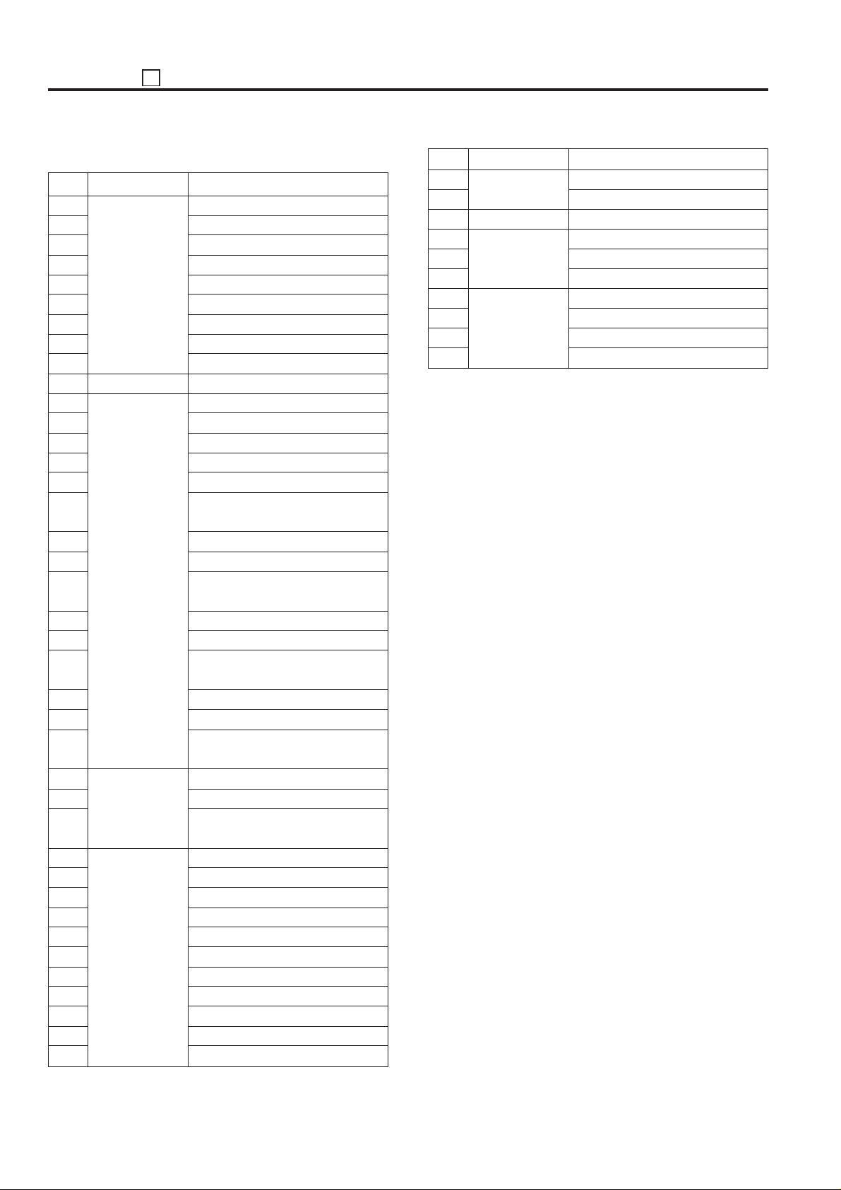
[< List of Parts to be Replaced (fixed) >
No.
1
2
3
4
5
6
7
8
9
10
11
12
13
14
15
16
17
18
19
20
21
22
23
24
25
26
27
28
29
30
31
32
33
34
35
36
37
38
39
Unit
Drum cartridge
(include charging corona unit)
Developing unit
Paper feed unit
By-pass paper
feed unit
Fixing unit
Cleaning blade
Charging wire
Charging control plate
Cleaner mount assembly
Charging wire cleaning block (C)
Charging wire cleaning block (D)
Transfer/Separation charging wire
OPC drum
Separation claw
Developer
(Tray: 1) –
(Tray: 1) –
(Tray: 1) –
(Tray: 2) Separation rubber
(Tray: 2) Paper feed rubber
(Tray: 2) Double feed prevention
rubber
(Tray: 3) Separation rubber
(Tray: 3) Paper feed rubber
(Tray: 3) Double feed prevention
rubber
(Tray: 4) Separation rubber
(Tray: 4) Paper feed rubber
(Tray: 4) Double feed prevention
rubber
(Tray: 5) Separation rubber
(Tray: 5) Paper feed rubber
(Tray: 5) Double feed prevention
rubber
(By-pass) Separation rubber
(By-pass) Paper feed rubber
(By-pass) Double feed prevention
rubber
Fixing cleaning roller
Fixing roller (A)
Fixing cleaning pad
Fixing roller (upper)
Fixing claw (upper)
Heat insulating sleeve
Fixing roller (lower)
Fixing claw (lower)
Fixing bearing (upper)
Bearing
Fixing bearing
Parts name
No.
40
41
42
43
44
45
46
47
48
49
Unit
Fixing unit
Machine inside
DF-311
FS-105
Parts name
Fixing heater lamp 1
Fixing heater lamp 2
Toner filter
Paper feed roller
Separation roller
Separation pad
(Tray 2) Paper exit roller (A)
(Tray 3) Paper exit roller (A)
Staple unit (front)
Staple unit (rear)
5 - 22
Page 24
25 ADJUSTMENT
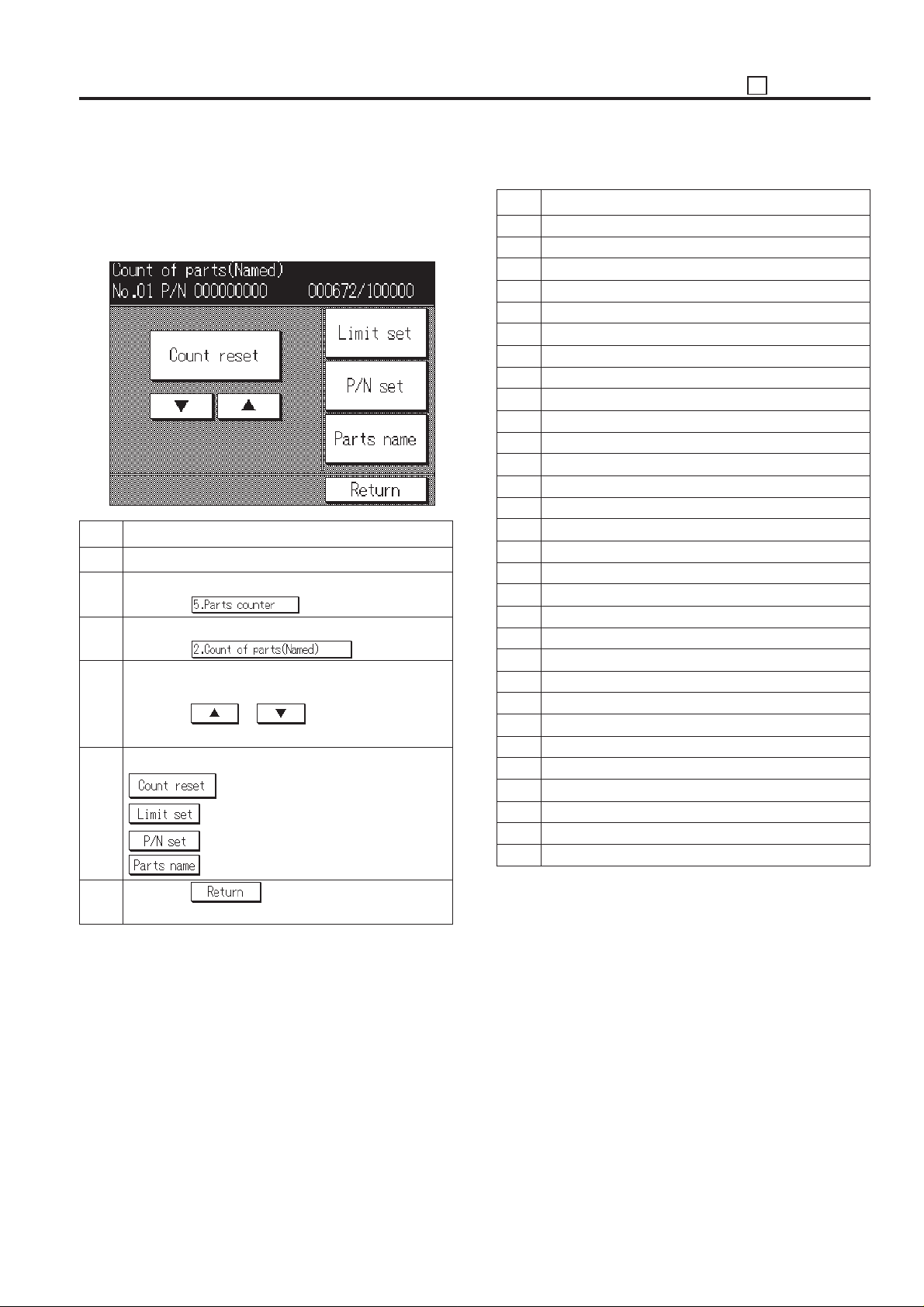
2. Copy count display and count reset by parts to
be replaced (Named; arbitrarily)
Set the limit value for the parts to be replaced, parts No., parts
name setting, copy count display and count reset.
[Copy count screen by parts to be replaced (Named)]
Step Operation procedure
1 Enter the 25 mode.
2 [25 Mode Menu Screen]
Press the key.
3 [Parts counter menu screen]
Press the key.
4 [Copy count screen by parts to be replaced
(Named)]
Press the or to select the data to be
set or changed.
5 Following items can be set below.
: To clear the copy count.
: To enter the limit value (6-digit).
: To enter the parts number (9-digit).
: To enter the parts name.
< List of Parts to be Replaced (arbitrarily) >
No.
When copy count (at the paper exit is completed)
1
When copy count (at the paper exit is completed)
2
When copy count (at the paper exit is completed)
3
When copy count (at the paper exit is completed)
4
When copy count (at the paper exit is completed)
5
When copy count (at the paper exit is completed)
6
When copy count (at the paper exit is completed)
7
When copy count (at the paper exit is completed)
8
When copy count (at the paper exit is completed)
9
When copy count (at the paper exit is completed)
10
When copy count (at the paper exit is completed)
11
When copy count (at the paper exit is completed)
12
When copy count (at the paper exit is completed)
13
When copy count (at the paper exit is completed)
14
When copy count (at the paper exit is completed)
15
When copy count (at the paper exit is completed)
16
When copy count (at the paper exit is completed)
17
When copy count (at the paper exit is completed)
18
When copy count (at the paper exit is completed)
19
When paper is fed from tray 5 (DB-208)
20
When paper is fed from by-pass tray
21
22
When paper is fed from tray 2
23
When paper is fed from tray 3
24
When paper is fed from tray 4
25
When paper is fed from ADU
26
When paper is exited from main body
27
When original is fed into RADF
28
When original is fed into RADF
29
When original is fed into RADF
30
Count timing
–
6 Press the key, then return to copy count
screen by parts to be replaced.
5 - 23
Page 25
ADJUSTMENT 25
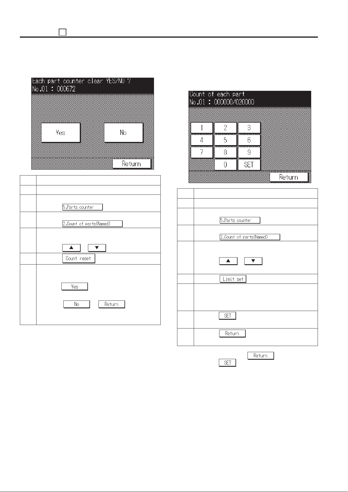
(1) Count resetting method
[Count reset screen by parts to be replaced (Named)]
Step Operation procedure
1 Enter the 25 mode.
2 [25 Mode Menu Screen]
Press the key.
3 [Parts counter menu screen]
Press the key.
4 [Copy count screen by parts to be replaced
(Named)]
Press the or to select the data.
5 Press the key.
6 [Count reset screen by parts to be replaced
(Named)]
Press the key to clear the copy count that
has been selected.
Press the or key, then the
copy count is not reset and return to the copy count
screen by parts to be replaced (Named).
(2) Count limit setting method
Enter the new limit value from the numeric key on the screen.
[Count limit setting screen by parts to be replaced
(Named)]
Step Operation procedure
1 Enter the 25 mode.
2 [25 Mode Menu Screen]
Press the key.
3 [Parts counter menu screen]
Press the key.
4 [Copy Count Screen by parts to be replaced
(Named)]
Press the or to select the data to be
set or changed.
5 Press the key.
6 [Copy count limit setting screen by parts to be
replaced (Named)]
Enter new value using the numeric keys.
7 Press the key to enter the limit value that has
been entered.
8 Press the key to return to the copy count
screen by parts to be replaced (Named).
Caution: When pressing the key without press-
ing the
changing a new limit value and returns to the copy
count screen by parts to be replaced (Named).
Reference:
The right side of the limit value will be marked as “*”
if the copy count exceeds its limit value.
key, the setting is complete without
5 - 24
Page 26
25 ADJUSTMENT
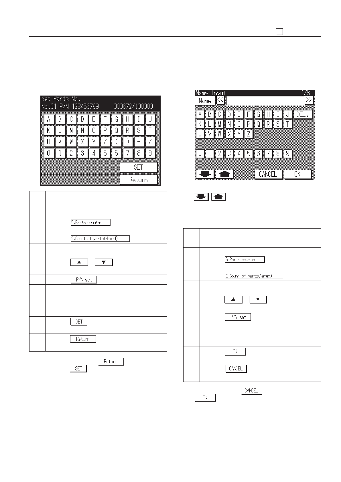
(3) Parts No. setting
Enter the new parts No. (9-digit) from the numeric and alphabet
keys on the screen.
[Parts No. setting screen by parts to be replaced
(Named)]
Step Operation procedure
1 Enter the 25 mode.
2 [25 Mode Menu Screen]
Press the
3 [Parts counter menu screen]
Press the key.
4 [Copy Count Screen by parts to be replaced
(Named)]
Press the
set or changed.
5 Press the key.
6 [ Parts No. Setting Screen by parts to be replaced
(Named)]
Enter new parts No. using the numeric and alphabet
keys.
7 Press the key to enter the parts No. that has
been entered.
8 Press the key to return to the copy count
screen by parts to be replaced (Named).
Caution: When pressing the key without press-
ing the
changing a new parts No. and returns to the copy
count screen by parts to be replaced (Named).
or to select the data to be
key, the setting is complete without
key.
(4) Parts name setting
Enter the new parts name from the keys on the screen.
[Parts Name Setting Screen by parts to be replaced
(Named)]
There are three screen in the input screen and are changed
with
• Alphabet (a capital letter), numeric number
• Alphabet (a small letter), numeric number
• Symbol, numeric number
Step Operation procedure
1 Enter the 25 mode.
2 [25 Mode Menu Screen]
3 [Parts counter menu screen]
4 [Copy Count Screen by parts to be replaced
5 Press the
6 [Parts Name Setting Screen by parts to be re-
7 Press the key to enter the parts name that
8 Press the key to return to the copy count
*1: When pressing the key without pressing the
, key.
Press the
Press the key.
(Named)]
Press the or to select the data to be
set or changed.
placed (Named)]
Enter new parts name using the keys on the screen.
has been entered. *1
screen by parts to be replaced (Named).
key, the setting is completed without setting a
parts name and returns to the copy count screen by parts
to be replaced (Named).
key.
key.
5 - 25
Page 27
ADJUSTMENT 25
[7] Password setting
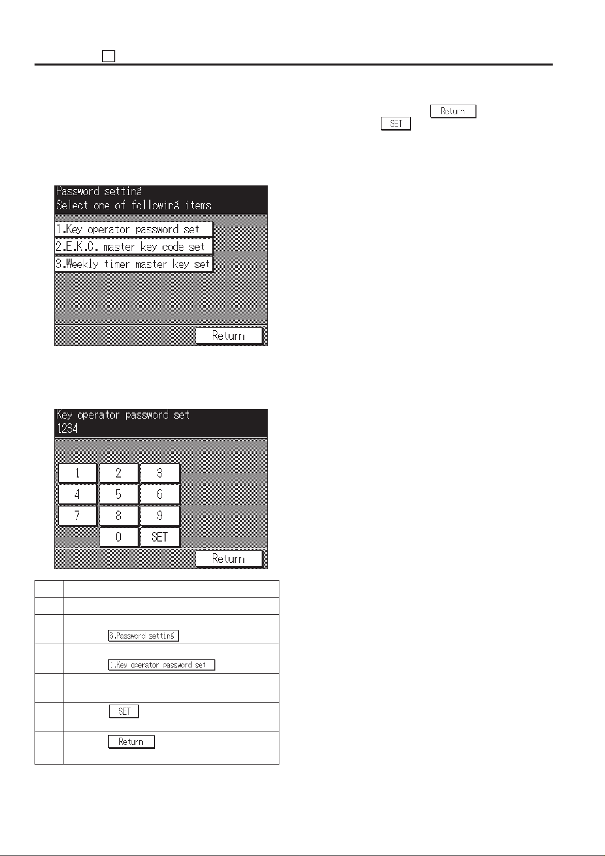
This function sets the password to enter each mode.
In the 25 mode menu screen, select the [6. Password setting],
then appear the password setting menu screen will appear.
Select the password to be adjusted/entered in this screen.
[Password setting menu screen]
1. Setting Key Operator Password
This function sets the password to enter the key operator
mode.
[Key operator password setting screen]
Caution: When pressing the
ing the
ever the new password will not be entered and the
password setting menu screen will return.
Reference:
When setting a password to “0000”, the key operator mode can
be used without a password.
key, the setting is complete. How-
key without press-
Step Operation procedure
1 Enter the 25 mode.
2 [25 Mode Menu Screen]
Press the
3 [Password Setting Menu Screen]
Press the key.
4 [Key operator password setting screen]
Enter 4-digit new password from the numeric key.
5 Press the key to set the password that has
been entered.
6 Press the key to return to the password
setting menu screen.
key.
5 - 26
Page 28
25 ADJUSTMENT
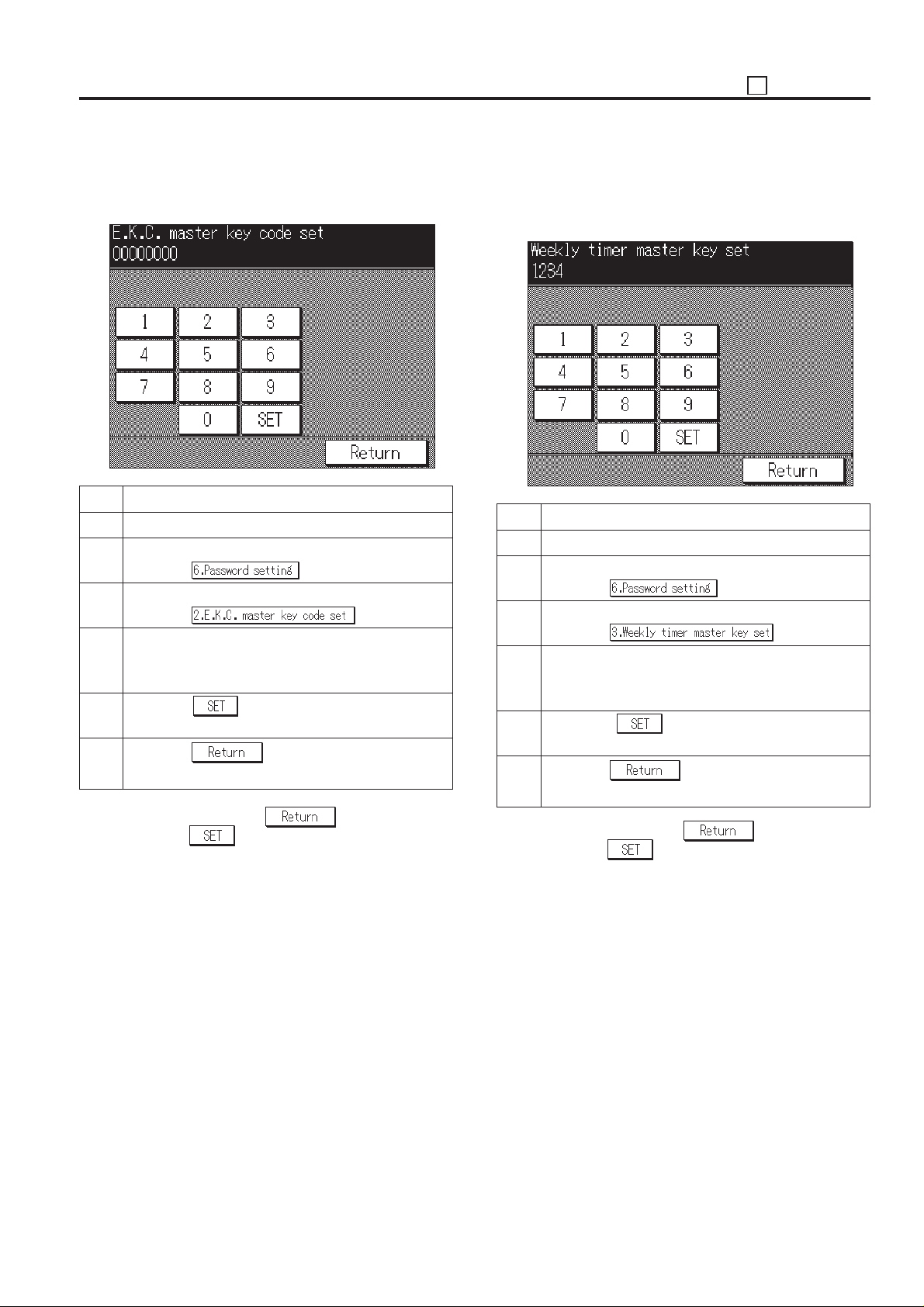
2. Setting the EKC Master Key Code
This function sets the EKC master key code.
[EKC master key code setting screen]
Step Operation procedure
1 Enter the 25 mode.
2 [25 Mode Menu Screen]
Press the key.
3 [Password Setting Menu Screen]
Press the key.
4 [EKC master key code setting screen]
Enter 8-digit new EKC master key code using the
numeric key.
5 Press the key to enter the EKC master key
code that has been entered.
6 Press the key to return to the password
setting menu screen.
Caution: When pressing the key without press-
ing the
changing a new EKC master key code and returns
to the password setting menu screen.
Reference:
When setting the EKC master key code to “00000000”, the
EKC setting mode can be used without a password (EKC
master key code).
key, the setting is complete without
3. Setting the Weekly Timer Master Key Code
This function sets the weekly timer master key code required
for entering the various weekly timer set mode.
[Weekly timer master key code setting screen]
Step Operation procedure
1 Enter the 25 mode.
2 [25 Mode Menu Screen]
Press the key.
3 [Password Setting Menu Screen]
Press the key.
4 [Weekly timer master key code setting screen]
Enter 4-digit new weekly timer master key code using
the numeric key.
5 Press the key to enter the weekly timer
master key code that has been entered.
6 Press the key to return to the password
setting menu screen.
Caution: When pressing the key without press-
ing the
changing a new weekly timer master key code and
returns to the password setting screen.
Reference:
When setting the master key code to “0000”, the weekly timer
mode can be used without a password.
key, the setting is complete without
5 - 27
Page 29
ADJUSTMENT 25
[8] Setting Phone Number of the Service
Center
This function displayes the phone and fax numbers of the
service center which is indicated on the screen if a service call
is required.
This function is not related to KRDS functions. It is designed
only for indicating the data on the screen.
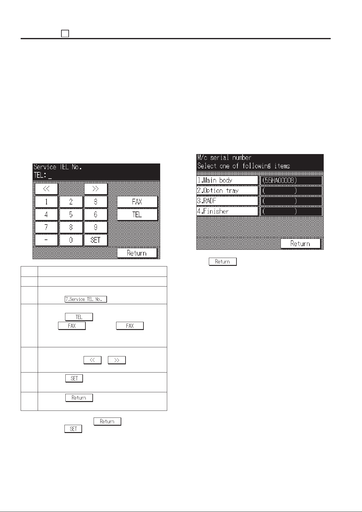
1. Setting phone and fax number of the service
center
Select [7. Service TEL No.] in the 25 Mode Screen.
Service Center Number Setting Screen will appear.
[Service center number setting screen]
[9] Setting the Serial Number
This function is used to display, set and change the serial
number of the main body or optional units.
The serial numbers can be read from KRDS.
1. Serial number display procedure
Select [8. M/c serial number] in the 25 Mode Screen. The serial
number setting screen will appear.
The item name and serial number are displayed on the serial
number setting menu screen. Each serial number is displayed
at the right side of the each unit.
[Serial Number Setting Screen]
Step Operation procedure
1 Enter the 25 mode.
2 [25 Mode Menu Screen]
Press the
3 [Service center number setting screen]
Press the key to set the phone number
and the key to set the number,
and input the number (Max. 16-digit) using the numeric keys on the screen.
4 When input has been mistaken, rewrite it after mov-
ing the cursor with
with the Stop/clear button to input again.
5 Press the key to enter the number that has
been entered.
6 Press the key to return to the 25 mode
menu screen.
Caution: When pressing the key without press-
ing the
ever the new phone number will not be entered and
the 25 mode menu screen will return.
key, the setting is complete. How-
key.
or key, or delete all
Press the key to end setting and return to the 25
mode menu screen.
Caution: If the unit (option) is not installed, the serial number
is not displayed.
5 - 28
Page 30
25 ADJUSTMENT
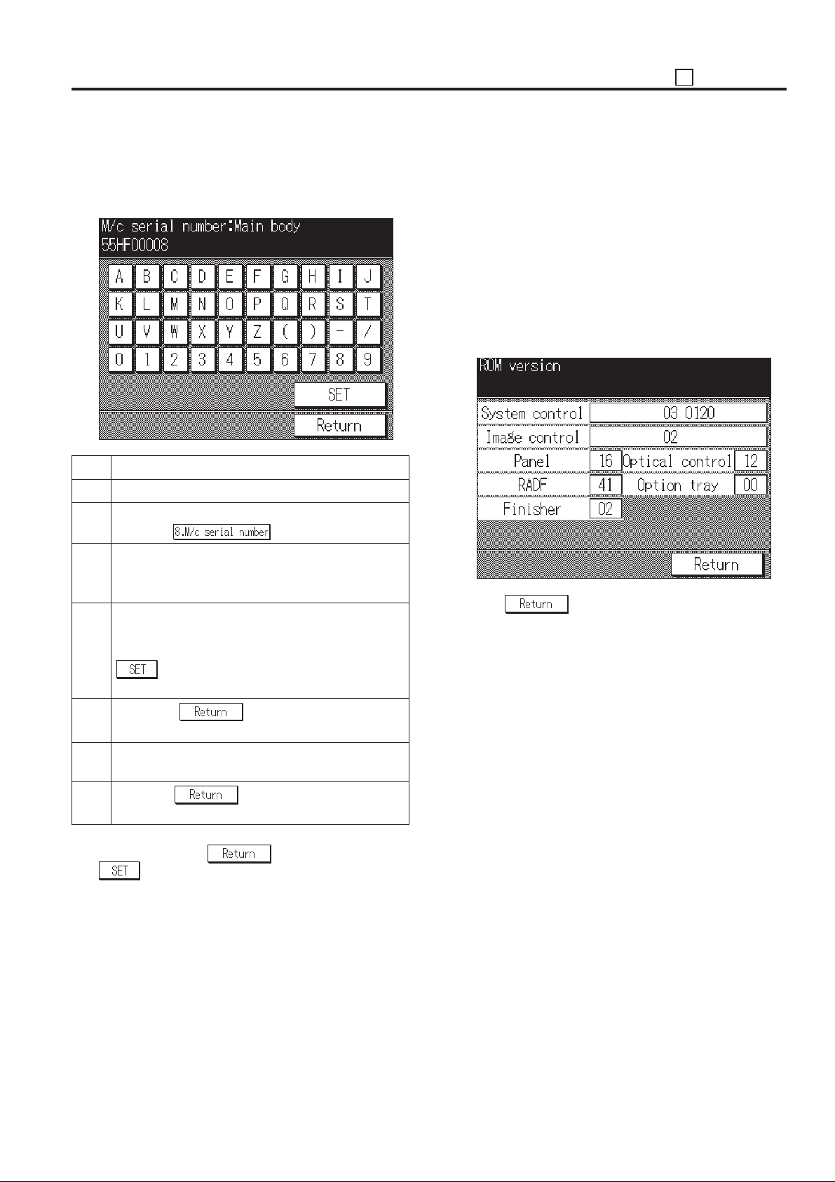
2. Setting and changing serial number
On the serial number setting screen, select the desired item,
then each serial number setting screen will appear.
[Serial number setting screen]
Step Operation procedure
1 Enter the 25 mode.
2 [25 Mode Menu Screen]
Press the key.
3 [Serial number setting menu screen]
Press the key corresponding to the desired item on
the screen.
4 [Serial number setting screen]
Enter the 9-digit serial number from the alphabet and
numeric keys on the screen and then press the
key to enter the number that has been en-
tered.
[10] Displaying the ROM Version
Display ROM version mounted to the machine.
1. ROM version viewing method
In the 25 mode menu screen, select [9. ROM version], then
appear the ROM version display screen will appear.
The item name and ROM version are displayed on the ROM
version display screen. Each serial number is displayed at the
right side of each item.
When there is an option not installed, the applicable position is
a blank.
[ROM Version Display Screen]
Press the key to end this screen and return to the
25 Mode Screen.
5 Press the key to return to the serial
number setting menu screen. *1
6 When changing the serial number of other item,
repeat steps 3 to 5.
7 Press the key to return to the 25 mode
menu screen.
*1: When pressing the key without pressing the
key, the setting is complete. However the new
serial number will not be entered and the serial number
setting menu screen will return.
5 - 29
Page 31
ADJUSTMENT 25
[11] KRDS Setting
This function selects whether to use KRDS.
KRDS allows the copy machine to call up the host computer
periodically and also when there is an abnormality. Also data
in the copier can be changed from the host computer.
KRDS can execute the above functions for the following data:
a. Data on the copier's status such as total and PM count.
b. Data on the frequency of the partial copier such as RADF
paper feed count.
c. Data on the copier's error status such as SC (F) /JAM
occurrence point and count.
d. Data on the various adjustments
To use KRDS, set up as follows:
1. Initialize KRDS memory.
2. Set the type of modem and line.
3. Enter host password.
4. Set phone number.
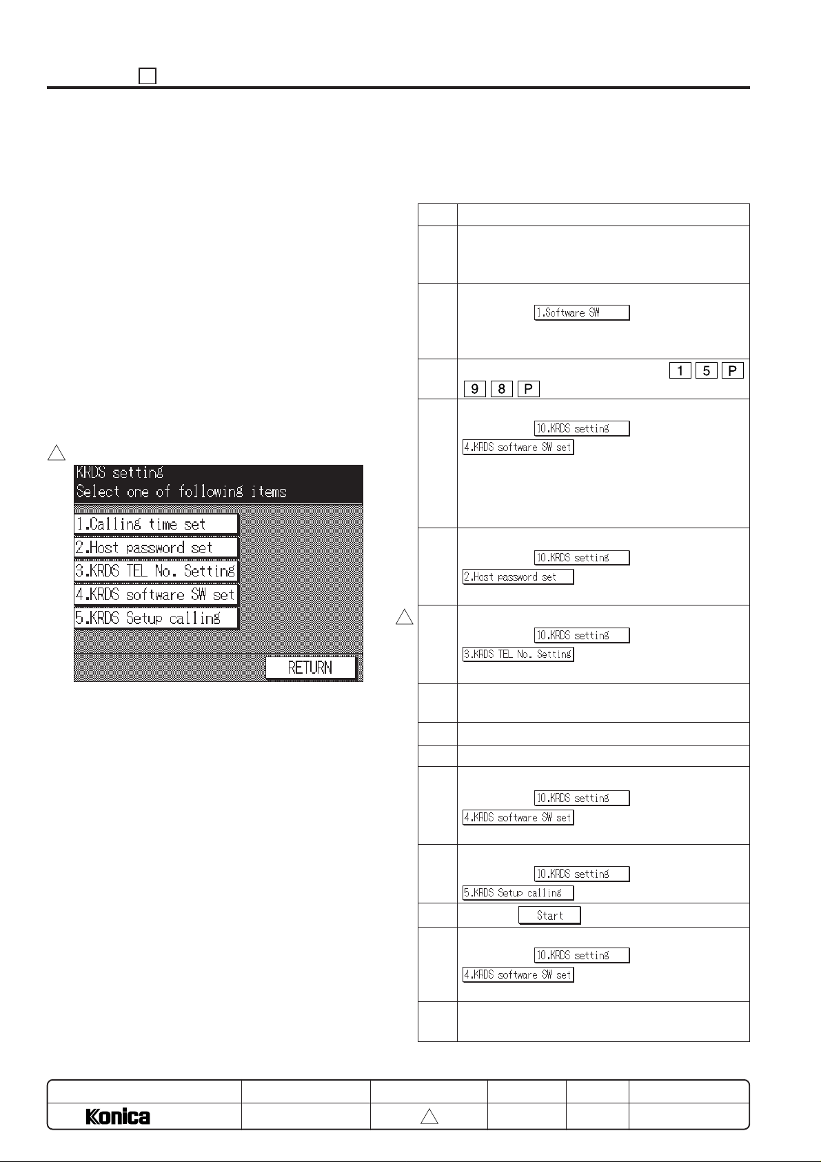
[KRDS Setting Menu Screen]
3
[12] KRDS Set Up
1. KRDS set up item
KRDS set up procedure
Step Operation procedure
1 Turn off the modem and connect to the copier using
a modem cable (RS-232C, 25P-25P straight cable)
and wall jack using a modular cable to the modem.
2 Setting the KRDS connection recognition
(25 mode →
Set copier software DIPSW 12-6 (KRDS connection
recognition) to “1”.
3 Initialize KRDS memory. (47 mode →
→ Start print button ON)
4 Set KRDS software SW.
(25 mode → →
(Select type of modem and
dial mode)
Select the type of modem from the bit pattern 0 to 6
of the KRDS software SW No.1 and dial mode from
the bit pattern 7.
5 Host password setting.
(25 mode →
)
(Refer to *1 and *2)
6 KRDS phone number setting.
3
(25 mode →
)
(Refer to *3)
7 Turn off the SW1 (main power) and SW2 (sub power)
of the copier.
8 Turn on the power switch of the modem.
9 Turn on the SW1 (main power) of the copier.
10 Check the set up flag setting condition.
(25 mode → →
→ check that the data on the
switch No.33 and bit No.0 indicates “0” (not yet).
11 Preform KRDS set up calling.
(25 mode →
)
)
→
→
→
MODEL
7040
MANUAL
SERVICE HANDBOOK
12 Press the key to start set up.
13 Check the finishing of set up.
(25 mode → →
switch No.33 and bit No.0 indicates “1” (finished).
14 Turn off the SW1 (main power) and SW2 (sub power)
of the copier.
REVISED EDITION
5 - 30
3
DATE
Mar. 1999
→ Completes if the data on the
PAGE
5-30
METHOD
REPLACEMENT
Page 32
25 ADJUSTMENT
*1: Host password must be 5-digit.
*2: Host password 1 must be specified.
*3: For both the copier and the host side, copier phone
number and host phone number 1 must be specified.
*4: Refer to the manual of the modem about specifications for
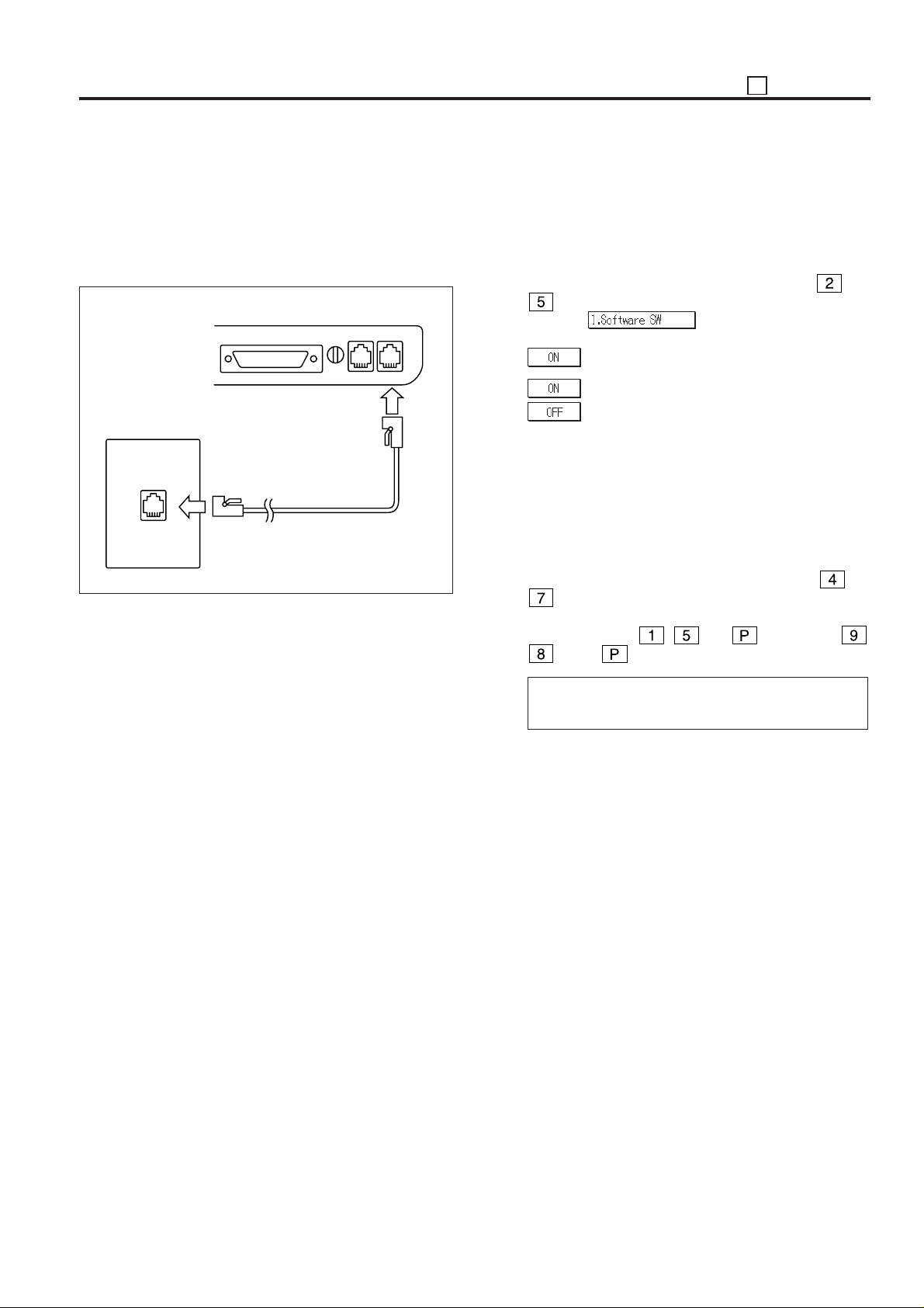
connecting with the modular cable.
LINETEL
Modem
Wall jack
Modular cable
2. Setting the KRDS connection recognition.
(1) Plug the power cord of the copier to the outlet. (When the
SW1 (main power) and SW2 (sub power) of the copier
remain off.)
(2) Turn on the SW1 (main power) when the SW2 (sub
power) remains off.
(3) Turn on the SW2 (sub power) while pressing
and
of the copy quantity setting buttons simultaneously.
(4) Select the
on the 25 mode menu screen.
(5) Select the bit No.6 of the switch No.12, and then press the
key.
: KRDS connect
: KRDS not connected
Caution: If the copier software DIPSW 12-6 (KRDS recogni-
tion) is not selected to “1”, the menu of the KRDS
can not be selected.
3. Initializing KRDS memory
(1) Turn off the SW2 (sub power) when the SW1 (main
power) remains on.
(2) Turn on the SW2 (sub power) while holding down
of the copy quantity setting buttons simultaneously.
(3) Press the start print button after pressing the copy quan-
tity setting button
, and button, then ,
, finally button again.
and
I/O check mode
< 15 - 98 > IN: – – OUT: NOW
(4) “NOW” indication will be changed to “FIN” on the mes-
sage display.
* If takes approximately 20 minutes to complete if the
machine is equipped with the memory card.
(5) Turn off the SW2 (sub power).
5 - 31
Page 33
ADJUSTMENT 25
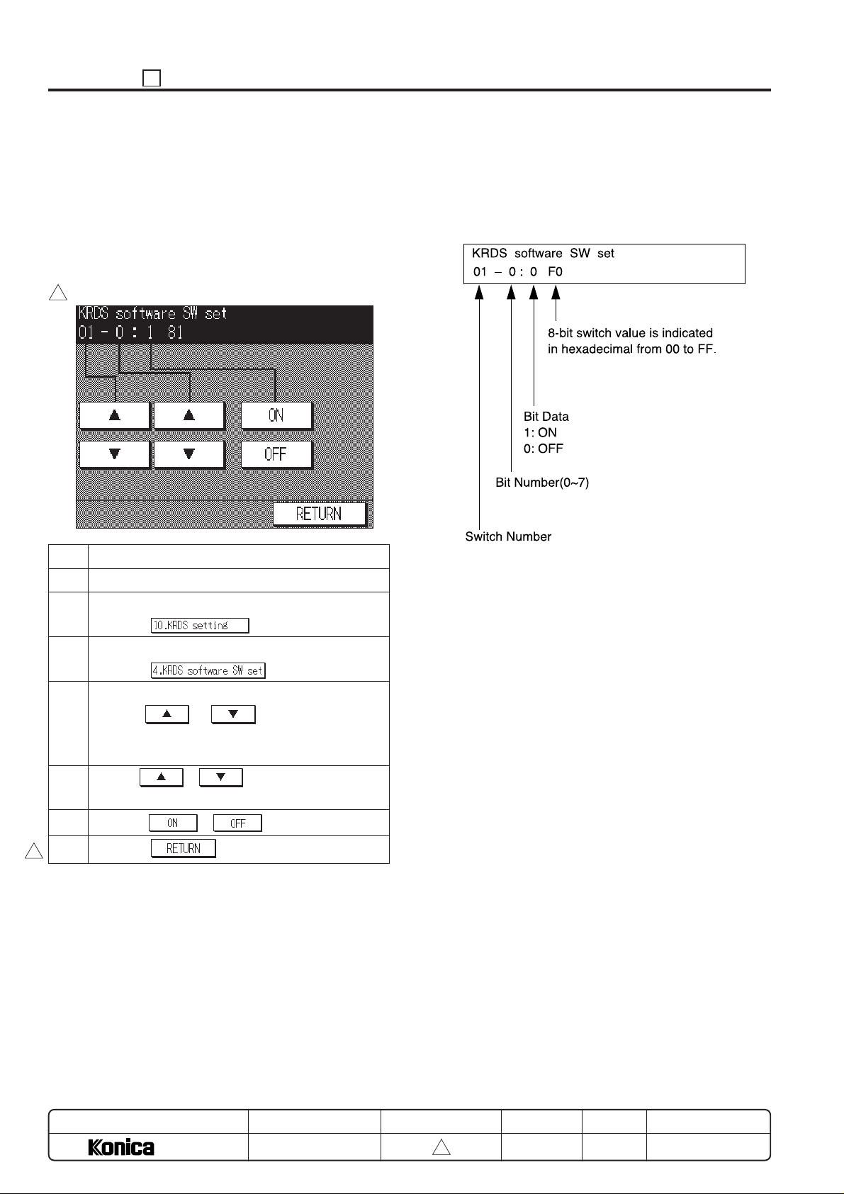
4. Setting KRDS software SW
This function allows adjustment of the KRDS software switches.
Caution: Adjust the software switch while checking the switch
and bit number since the memory is rewritten every
time the bit data (1 or 0) is changed.
Any bit data that has been incorrectly changed must
be returned to the original data.
[KRDS software SW set screen]
3
Step Operation procedure
1 Enter the 25 mode.
2 [25 mode menu screen]
Press the
3 [KRDS setting menu screen]
Press the
4 [KRDS software SW set screen]
Use the or key to set the switch
number.
(Refer to *1)
5 Use the
(Refer to *1)
6 Press the or key to set the bit data.
or key to set the bit number.
.
.
*1:
• The bit of the switch is written in the non-volatile RAM
every time it is changed.
• The numbers shown in the message area are defined as
follows:
For each switch function, refer to “List of KRDS Software DIP
SW”.
7 Press the key to end the setting.
3
MODEL
7040
SERVICE HANDBOOK
MANUAL
REVISED EDITION
5 - 32
3
DA TE
Mar. 1999
PAGE
5-32
METHOD
REPLACEMENT
Page 34
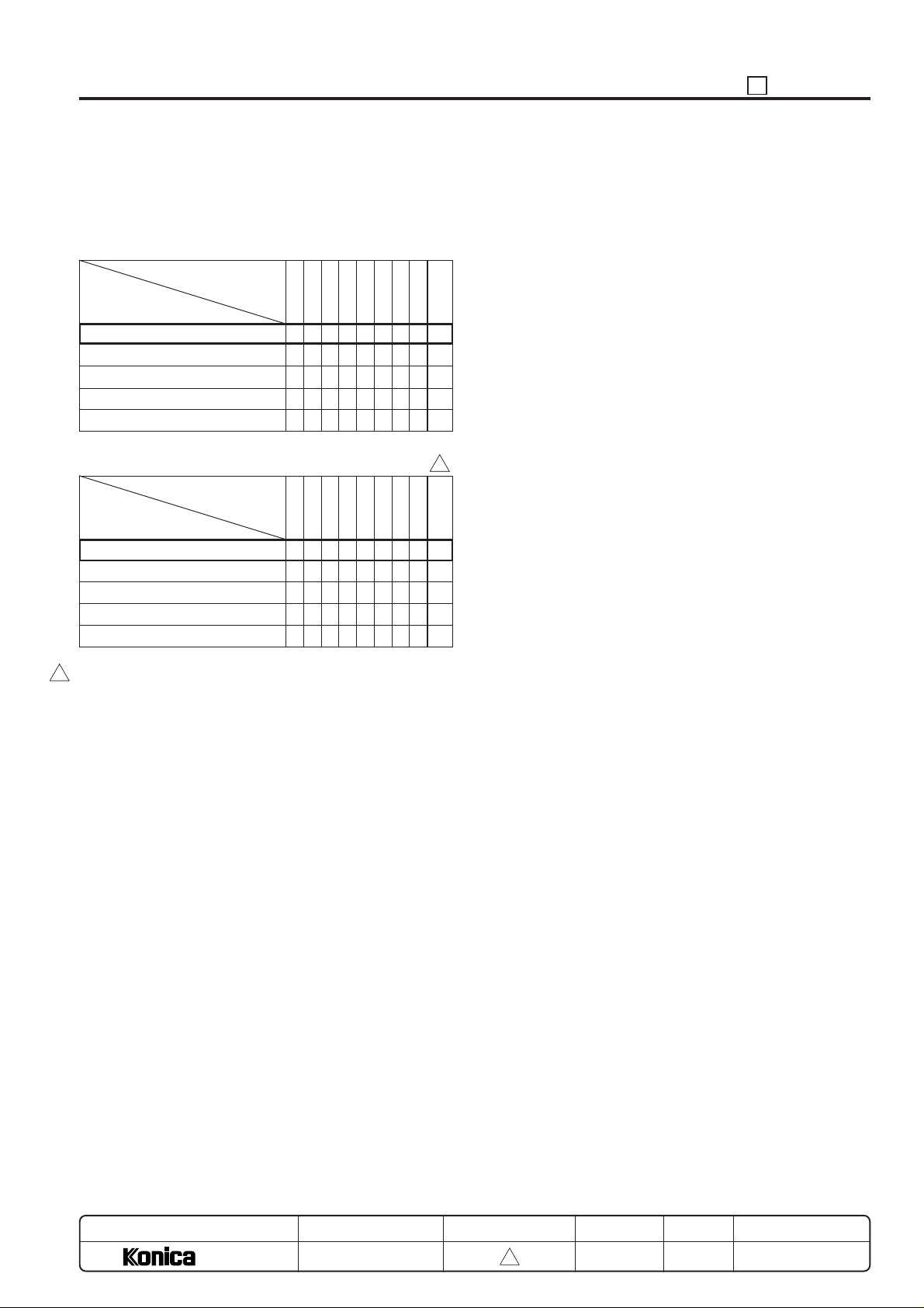
5. Setting type of modem and line
(1) Using the switch No. 01, enter the modem and line data
into the bits 0 to 7, referring to the following table.
<If telephone line type is “Pulse”>
Bit No.
Modem
initialization command
AT&FE0Q0V1X0S0=1&S0
AT&FE0Q0V1X0S0=1&S0&D2&C1
AT&FE0Q0V1X0S0=1&S0%E0
AT&FE0Q0V1X0S0=1&S0&D2
AT&FE0Q0V1X0S0=1&S0&M5
76543210 ∗
0000000101
0000001002
0000001103
0000010004
0000010105
25 ADJUSTMENT
<If telephone line type is “Tone”>
Bit No.
Modem
initialization command
AT&FE0Q0V1X0S0=1&S0
AT&FE0Q0V1X0S0=1&S0&D2&C1
AT&FE0Q0V1X0S0=1&S0%E0
AT&FE0Q0V1X0S0=1&S0&D2
AT&FE0Q0V1X0S0=1&S0&M5
Example:
3
If the initialization command for the modem you are using is
AT&FE0Q0V1X0S0=1&S0 and you have a pulse-dial telephone line, enter the data for bits 7 to 0 as 00000001:
In hexadecimal <∗>, the value is expressed as 01. Be sure to
verify with the above charts whether or not the hexadecimal
<∗> output corresponds with the model being used.
Reference:
This machine has a telephone (modem) line type automatic
recognition setting function.
KRDS Software DIP SW:
Switch No.38 and bit No.0
Data 0: off (manual setting)
1: on (line type automatic recognition) (default)
As a result, if this switch is at “1”, Bit No. 7 of Switch No. 1 can
be either “0” or “1”.
76543210 ∗
1000000181
1000001082
1000001183
1000010084
1000010185
3
MODEL
7040
MANUAL
SERVICE HANDBOOK
REVISED EDITION
5 - 33
3
DATE
Mar. 1999
PAGE
5-33
METHOD
REPLACEMENT
Page 35
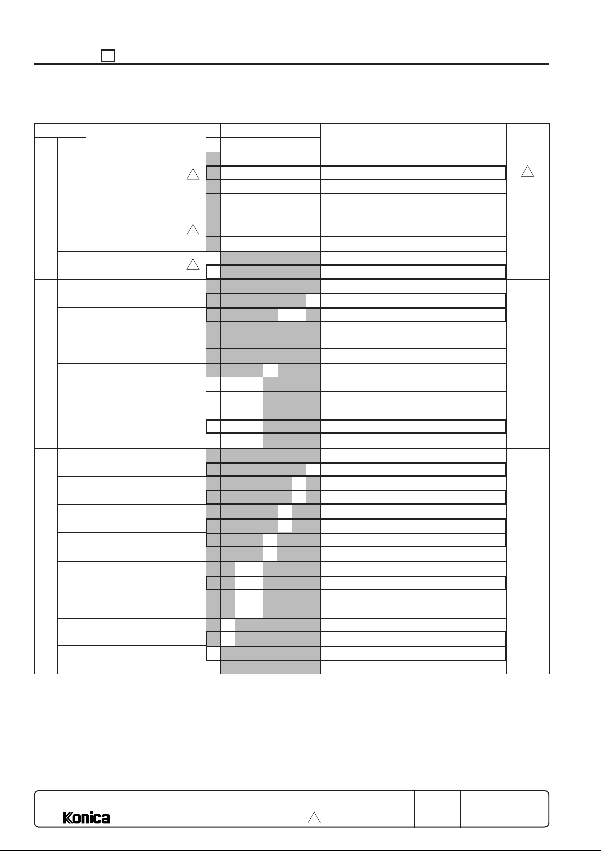
ADJUSTMENT 25
(2) List of KRDS Software DIP SW
byte
1
2
3
No.
bit
0 - 6
Select modem
7
Dial mode
0
Data character length
1 - 2
Parity and stop bit
3
Reserve
4 - 7
Baud rate
0
Local echo
1
Result code
2
Result code form
Function
(displayed result)
3
Set DCD signal operation
(carrier detect)
4 - 5
Set DSR signal operation
6
Check DSR signal
7
Check DCD signal
MSB
Bit pattern
76543210
0000000
3
0000001
0000010
0000011
0000100
3
0000101
1111111
0
3
1
Don't
care
0011
0100
0101
0110
0111
0
1
00
01
10
11
0
1
0
1
00
0
1
0
1
LSB
Description
No setting (No data is sent to modem.)
AT&FE0Q0V1X0S0=1&S0
AT&FE0Q0V1X0S0=1&S0&D2&C1
AT&FE0Q0V1X0S0=1&S0%E0
AT&FE0Q0V1X0S0=1&S0&D2
AT&FE0Q0V1X0S0=1&S0&M5
Manual setting (3 to 24 byte data is sent to modem.)
Pulse dial
Tone dial
1
8 bit (fixed)
No parity, stop bit 1 (fixed)
Even number of parity, stop bit 1
Odd number of parity, stop bit 1
No parity, stop bit 2
1200 bps
2400 bps
4800 bps
9600 bps
19200 bps
No setting
1
E0
No setting
Q0: Exist
No setting
V1: Word
No setting
&C1: ON only when the carrier is detected.
No setting
&S0: Keep ON
&S1: ON during online
&S2
off
on
off (fixed)
on
Default value
(Hexadecimal)
81
3
61
57
MODEL
7040
MANUAL
SERVICE HANDBOOK
REVISED EDITION
5 - 34
3
DATE
Mar. 1999
PAGE
5-34
METHOD
REPLACEMENT
Page 36
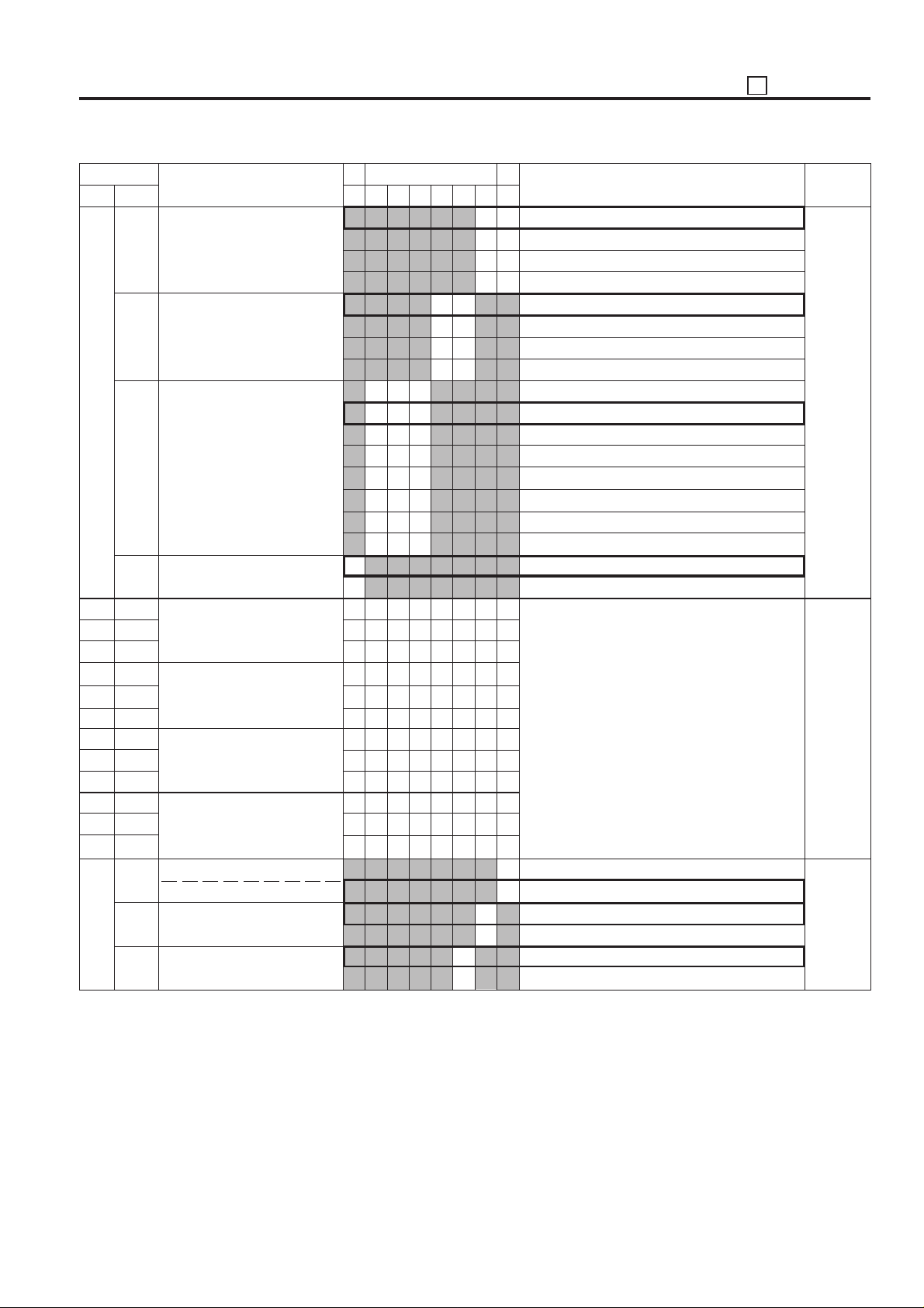
25 ADJUSTMENT
byte
4
5
6
7
8
9
10
11
12
13
14
15
16
17
No.
bit
0 - 1
Set DTR signal operation
2 - 3
Speaker control
4 - 6
Display speed when connection is completed and dial/
busy tone is detected.
7
Reset modem (This is set
prior to shipping.)
0 - 7
Arbitrary command registra-
0 - 7
tion area 1 (ASCII data)
0 - 7
0 - 7
Arbitrary command registra0 - 7
tion area 2 (ASCII data)
0 - 7
0 - 7
Arbitrary command registra0 - 7
tion area 3 (ASCII data)
0 - 7
0 - 7
Arbitrary command registra0 - 7
tion area 4
0 - 7
Command free setting
0
Set S register (bit 0 - 7)
S0:
1
S6: Wait time from off hook
2
S7: Off hook limit timer
Function
Automatic receive ring count
to dial start
MSB
76543210
0
1
Bit pattern
00
01
10
11
000
001
010
011
100
101
110
111
LSB
00
01
10
11
0
1
0
1
0
1
Description
No setting
&D0
&D1
&D2
No setting
M0: Keep off
M1: ON until communication starts
M2
No setting
X0: No indication of communication speed
X1: Indication of communication speed
Indication of communication speed; Detect dial tone
X2:
X3:
Indication of communication speed; Detect busy tone
X4:
Indication of communication speed; Detect dial and busy tone
non
non
No setting
&F: This is set prior to shipping.
Send ASCII data specified in this area to
modem
No setting
S0=: Effective data
No setting
S6=: Effective data
No setting
S7=: Effective data
Default value
(Hexadecimal)
10
00
01
5 - 35
Page 37
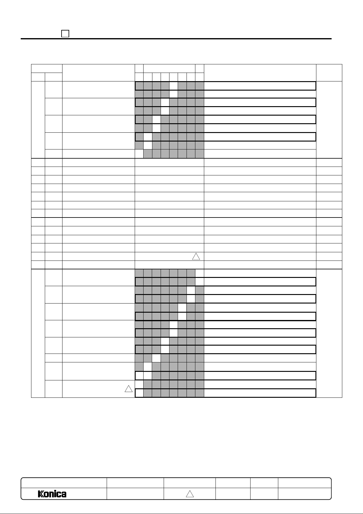
ADJUSTMENT 25
byte
17
18
19
20
21
22
23
24
25
26
27
28
29
30
31
No.
bit
3
S8: Dial stop time (sec.)
4
S9: Carrier recognize time
5
S10: Allowable carrier stop
Function
time
6
S11
7
Reserve
S0 data
S6 data
S7 data
S8 data
S9 data
S10 data
S11 data
Timer 1
Timer 2
Timer 3
Timer 4
Timer 5
Retry data; Timer 6
0
Call when SC error occurs
1
Call specify date
2
Call parts replace date
3
Call drum replace date
4
Call regular service date
5
6
Call regular transmit date
7
Select regular transmit
(Time and count)
Bit pattern
76543210
0
1
0
1
0
1
0
1
Don't
care
00 - FFH
00 - FFH
00 - FFH
00 - FFH
00 - FFH
00 - FFH
00 - FFH
00 - FFH
00 - FFH
00 - FFH
00 - FFH
00 - FFH
00 - FFH
0
1
0
1
0
1
Don't
care
0
1
0
3
1
LSBMSB
No setting
S8=: Effective data
No setting
S9=: Effective data
No setting
S10=: Effective data
No setting
S11=: Effective data
01H (1)
03H (3)
1EH (30)
03H (3)
06H (6)
0EH (14)
5FH(95)
20H (32) x 1sec
40H (64) x 1sec
0AH (10) x 100ms
20H (32) x 100ms
1EH (30) x 1sec
3
FFH (255) x 5ms
0
disable
1
enable
0
disable
1
enable
disable
enable
disable
enable
disable
enable
disable
enable
time
counter
Description
Default value
(Hexadecimal)
01
01
03
1E
03
06
0E
5F
20
40
0A
20
1E
FF
DF
MODEL
7040
MANUAL
SERVICE HANDBOOK
REVISED EDITION
5 - 36
3
DATE
Mar. 1999
PAGE
5-36
METHOD
REPLACEMENT
Page 38

25 ADJUSTMENT
byte
32
3
33
34
35
36
37
No.
bit
0
Call when optional configu-
Function
ration is changed
1
Report of toner replenishment
2
Report of JAM occur
frequently
3 - 7
Reserve
0
Set up flag
1 - 2
Radial interval
3 - 4
Radial count
5 - 6
Reserve
7
Line feed control
(when initializing modem)
0 - 1
Call JAM date (main body)
Valid copy quantity
2 - 3
Call ADF JAM date
Valid original feed quantity
4 - 5
Call JAM date
MCBJ setting
6 - 7
Call JAM date
MOBJ setting
Reserve
Reserve
Reserve
MSB
Bit pattern
76543210
Don't care
Don't care
00
01
3
10
11
Don't care
0
1
00
01
10
11
00
01
10
11
00
01
10
11
0
1
0
1
00
01
10
11
00
01
10
11
LSB
0
1
disable
enable
Description
disable
enable
disable
enable
0
not yet
1
finished
1 min.
3 min.
5 min.
7 min.
0
5
10
No limit
CR/LF: LF exist
CR: No LF
Copy quantity: level 1
Copy quantity: level 2
Copy quantity: level 3
Copy quantity: level 4
Original feed quantity: level 1
Original feed quantity: level 2
Original feed quantity: level 3
Original feed quantity: level 4
MCBJ: level 1
MCBJ: level 2
MCBJ: level 3
MCBJ: level 4
MOBJ: level 1
MOBJ: level 2
MOBJ: level 3
MOBJ: level 4
Default value
(Hexadecimal)
00
0A
3
55
00
MODEL
7040
MANUAL
SERVICE HANDBOOK
REVISED EDITION
5 - 37
3
DATE
Mar. 1999
PAGE
5-37
METHOD
REPLACEMENT
Page 39
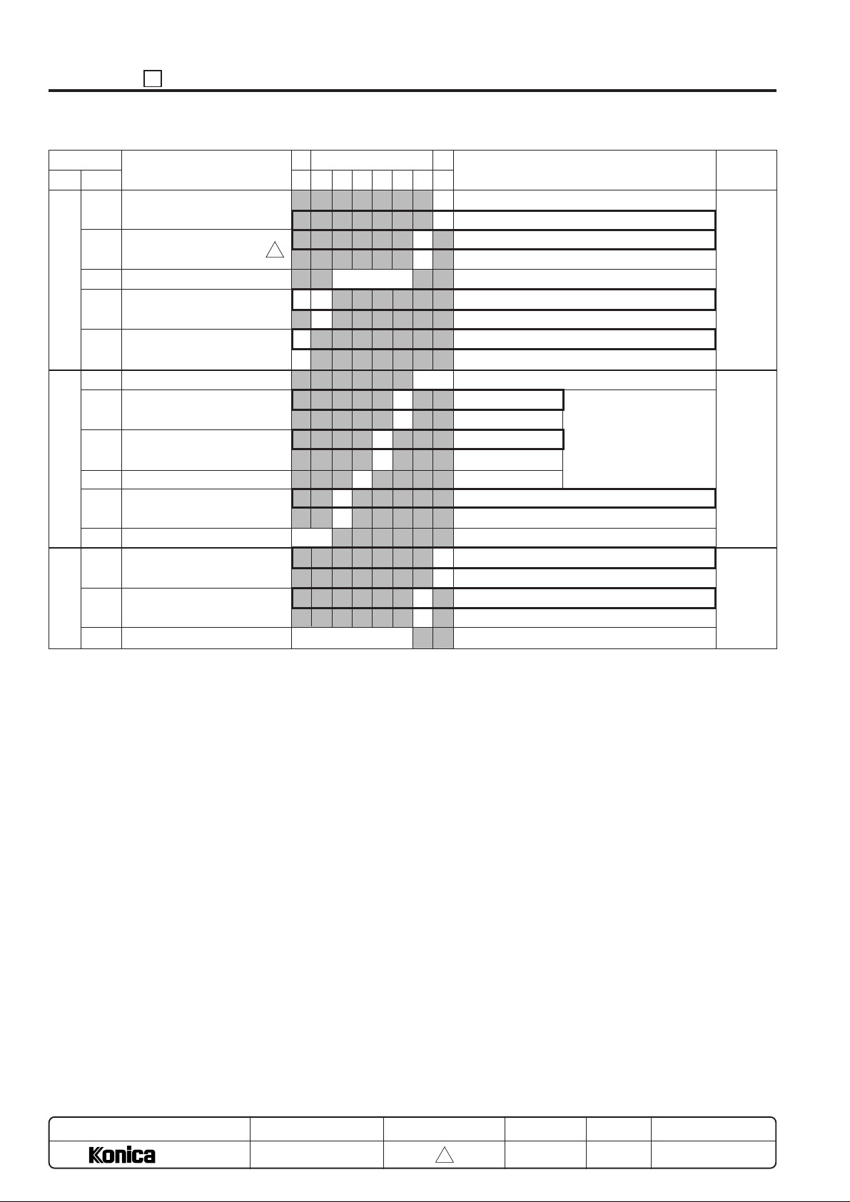
ADJUSTMENT 25
byte
38
39
40
No.
bit
0
Line type automatic recogni-
Function
tion
1
MSAD connection
2 - 5
Reserve
6
PM limit data length
7
Regular transmit communication
Sequence control
0 - 1
Reserve
2
RS-232 line error
K01_XX (refer to 1*)
3
Modem AT command error
K02_XX (refer to 1*)
4
Reserve
5
Force copy stop
(at host side)
6 -7
Reserve
0
Force copy stop
(at terminal equipment side)
1
Jam history data clear
2 - 7
Reserve
MSB
Bit pattern
76543210
3
Don't care
0
1
0
1
0
1
Don't
care
0
1
Don't care
Don't care
0
1
LSB
0
off
1
on
0
not connect
1
connect
Upper 2-digit fixed (for host)
All 6-digit (for host)
Call back communication
No call back communication
Don't care
copy enable
copy disable
copy enable
copy disable
disable
enable
0
disable
1
enable
0
disable
1
enable
Description
*1: For more detailed
information, refer to
error code list.
Default value
(Hexadecimal)
01
00
00
MODEL
7040
MANUAL
SERVICE HANDBOOK
REVISED EDITION
5 - 38
3
DATE
Mar. 1999
PAGE
5-38
METHOD
REPLACEMENT
Page 40
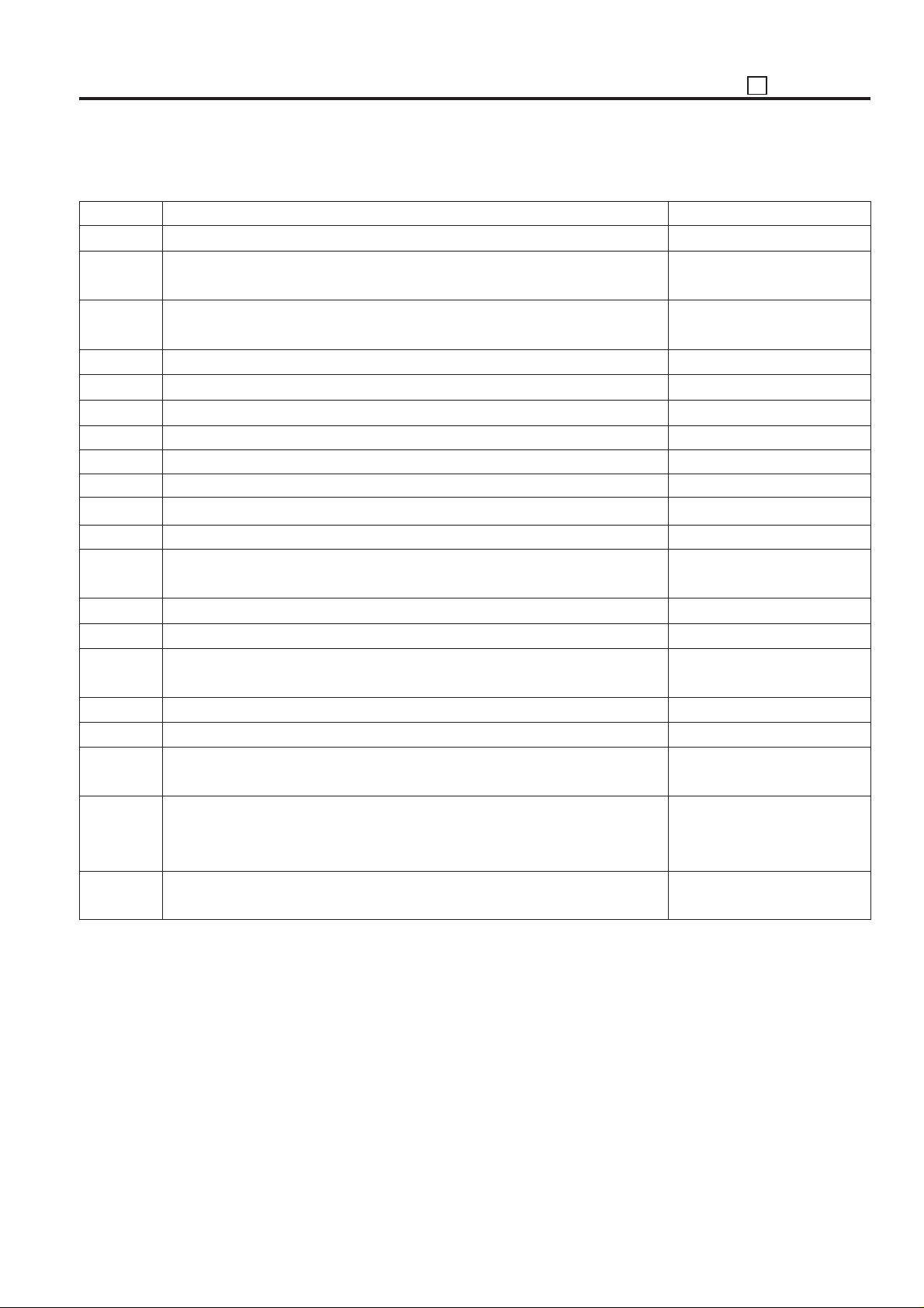
*1: Error code list
25 ADJUSTMENT
Error Code
K00_00
K00_01
K00_02
K00_03
K00_04
K00_05
K00_06
K00_07
K00_08
K00_09
K00_10
K00_11
K00_12
K00_13
K01_00
K01_01
K01_02
K01_03
K02_00
K02_01
Contents
Connection NG.
No response from other party.
(No detection of start text from host after establishing connection.)
Because copying is taking place, it is impossible to write to the non-volatile RAM
and the line is cut.
Password does not match.
Serial number does not match.
Syntactical error.
Write-in indication on an item for which write-in is impossible.
Unread item error.
Signal reception time-out after detection other party response.
Serial number registration completed.
Communications error due to generation of carrier OFF.
Dial tone is not detected within 5 seconds after setting of X2 and X4 commands.
Busy signal detected.
No tone detected for 5 seconds after input of @ command.
DTR went to OFF or in OFF state.
Cannot open RS-232C.
Cannot close RS-232C.
Response time-out from RS-232C task.
AT command error.
Initializing NG (MODEM).
Example: Modem initializing command no good.
Countermeasure
Redial, repeat reception standby.
Redial, repeat reception standby.
Temporarily stop copying.
Check password.
Check serial number.
Redial, repeat reception standby.
Re-operation on host side.
Re-operation on host side.
Redial, repeat reception standby.
Check serial number.
Redial, repeat reception standby.
Check connection of telephone
line.
Redial.
Redial, repeat reception standby.
Check modem power source.
Check RS-232C cable connection.
Turn power on copier OFF and ON.
Turn power on copier OFF and ON.
Check modem power source.
Check RS-232C cable connection.
Turn power on copier OFF and ON.
Possibility of modem malfunction or software bug.
Check modem power source.
Check RS-232C cable connection.
5 - 39
Page 41
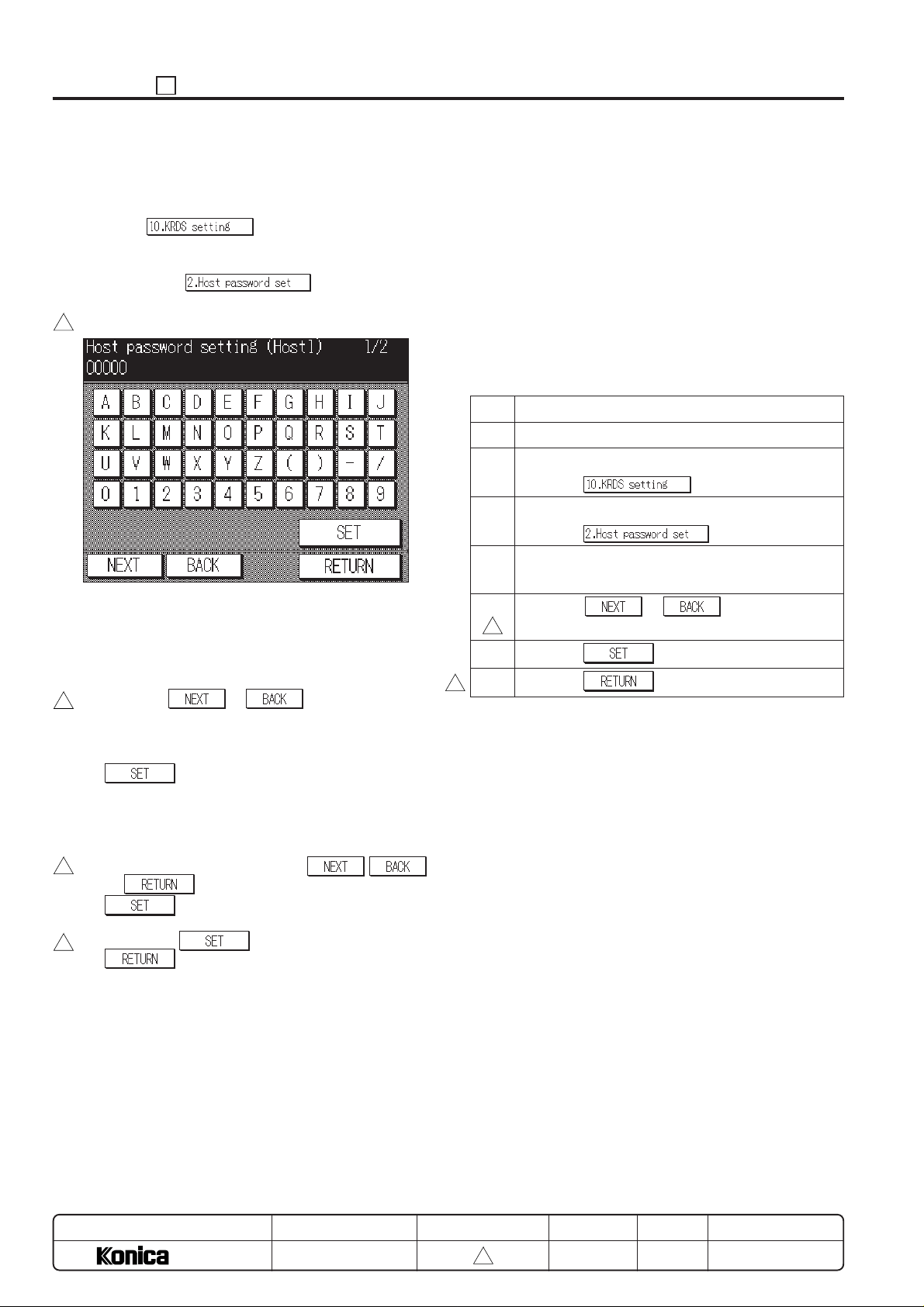
ADJUSTMENT 25
6. Setting host password
This function sets the host password.
(1) Screen selection
Select the
to display the KRDS setting menu screen as an initial
screen.
Then select the
password setting screen.
[Host password setting screen]
3
(2) Setting method
a. Two patterns can be used to set KRDS host pass-
word. The entry screen, screen contents and setting
method for each pattern are all the same. Each
message, however, is different.
b. Press the
3
screen.
c. Enter the host password, 5-digit number or alphabet,
with the numeric key on the screen and press the
key.
d. The firstly entered number or alphabet will be shifted
to the left end.
e. This password has been set to “00000” prior to ship-
ping.
f. After inputting the password, it the
3
or key is pressed before pressing the
key, the data that has been entered is
canceled.
g. Press the
3
key to set the entered password. The
screen will return to the KRDS setting menu screen.
in the 25 mode menu screen
to display the host
or key to 2change the
key, and then press the
* Note that the host password setting (Host1) must be
performed.
* • When controlling with a single host unit, nothing is
set to the host password setting (Host2).
• When controlling with 2 host units, set a password
different from (Host1) to the host password setting
(Host2).
Example of operation with 2 host units.
Host (1): Service
(Emergency call address host).
Host (2): Service
(Periodical transmission address host)
Step Operation procedure
1 Enter the 25 mode.
2 [25 mode menu screen]
Press the
.
3 [KRDS setting menu screen]
Press the
.
4 [Host password setting Screen]
Enter password consisting of number and alphabet.
5 Press the
screen, then enter password (up to 2 patterns).
3
or key to change the
6 Press the key.
7 Press the to end the setting.
3
,
MODEL
7040
MANUAL
SERVICE HANDBOOK
REVISED EDITION
5 - 40
3
DATE
Mar. 1999
PAGE
5-40
METHOD
REPLACEMENT
Page 42
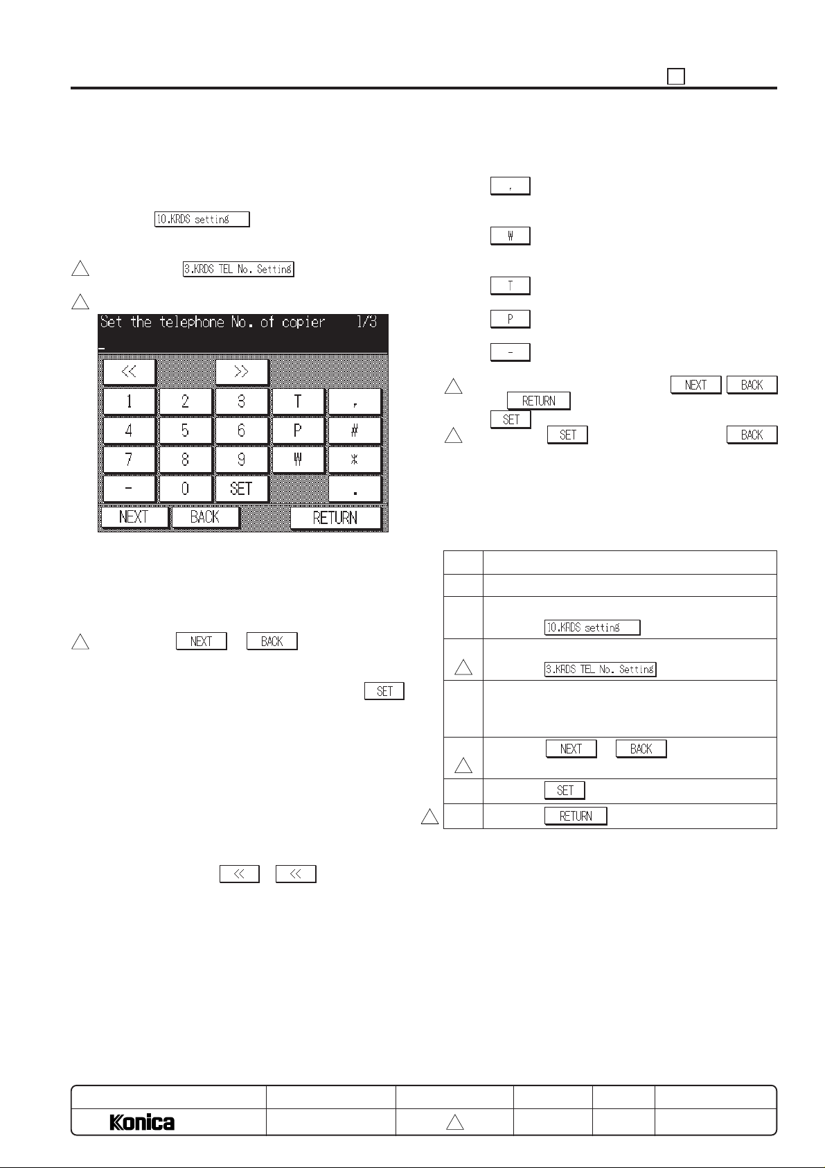
25 ADJUSTMENT
7. Setting the KRDS phone number
This function sets copier for KRDS and host phone number.
(1) Screen selection
Select the in the 25 mode menu screen
to display the KRDS setting menu screen as an initial
screen.
Then select the
3
TEL NO setting screen.
[KRDS TEL NO setting screen]
3
(2) Setting method
a. Three patterns can be used to set KRDS phone
number. The entry screen, screen contents and setting method for each pattern are all the same. Each
screen, however, is different.
b. Press the
3
or key to change the
screen.
c. Enter the phone number, 15-digit or less number, with
the numeric key on the screen and press the
key.
d. The entered number is displayed in the cursor section
displayed in the line 2 of the message display area.
The cursor shifts from left to right according to the
entered.
If more than 15 digit is entered, the number of the 15
digit is rewritten.
e. To reenter the phone number, press the Stop/clear
button to clear the data then enter the correct number.
f. If you wish to change the number of an arbitrary
position, press the
cursor to the desired position and reenter.
g. No data has been set for the second row of the
message area prior to shipping.
to display the KRDS
or key to move the
h. The keys except the numeric keys are defined as
follows:
Pause:
Wait temporarily for self-dial feed. (2 -3
sec.)
Wait:
Wait for dial tone such as asynchronous,
etc. (excluding sound guidance).
Tone Dial:
Indicate tone dial after this symbol
Pulse Dial:
Indicate pulse dial after this symbol
Symbol to divide numbers:
(This symbol is ignored when dialing.)
i. After inputting the password, it the
3
or key is pressed before pressing the
key, the data that has been entered is canceled.
j. Press the
3
key, and then press the
key to set the entered number. The screen will return
to the KRDS setting menu screen.
* • Note that the phone number setting (copier) and
phone number setting (Host1) must be performed.
• When controlling with a single host, nothing is set to
the phone number setting (Host2).
Step Operation procedure
1 Enter the 25 mode.
2 [25 mode menu screen]
Press the
.
3 [KRDS setting menu screen]
3
Press the
.
4 [KRDS TEL NO Setting Screen]
Enter phone number (15-digit or less) consisting of
number and alphabet with numeric key.
5 Press the or key to change the
screen, then phone number (up to 3 patterns).
3
6 Press the key.
7 Press the to end the setting.
3
,
MODEL
7040
MANUAL
SERVICE HANDBOOK
REVISED EDITION
5 - 41
3
DATE
Mar. 1999
PAGE
5-41
METHOD
REPLACEMENT
Page 43
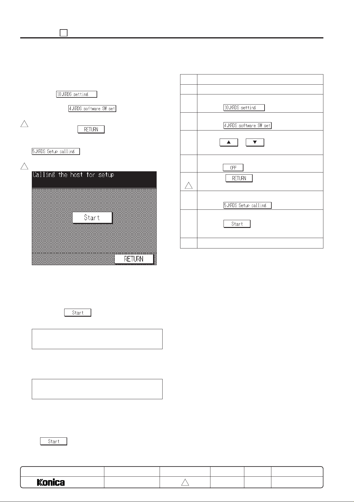
ADJUSTMENT 25
8. Calling KRDS set up
This function sends data for copier set up.
(1) Screen selection
Select the in the 25 mode menu screen
to display the KRDS setting menu screen.
Then select the
software SW set screen.
Check that the software DIP SW 33-0 is set to “0”. After
3
checking, press the
setting menu screen.
On the KRDS setting menu screen, select the
to display the calling host for setup
screen.
[Calling the host for setup screen]
3
to display the KRDS
key to return to the KRDS
c. Turn off the power to end the operation.
Step Operation procedure
1 Enter the 25 mode.
2 [25 mode menu screen]
Press the
3 [KRDS setting menu screen]
Press the
4 [KRDS software SW set screen]
Use the or key to select the switch
number to “33” and bit number “0”.
5 Check that bit data indicates “0”. If not, set to “0” to
press the
6 Press the key to return to the KRDS
3
setting menu screen.
7 [KRDS setting menu screen]
Press the
8 [Calling the host for setup Screen]
Press the key.
Check the message on the screen.
9 Turn off the power to end the operation.
key.
.
.
.
Caution: If the KRDS software DIPSW 33-0 (Set up flag) is
not selected to “0” (not yet). The KRDS setup calling
screen can not be selected.
(2) Setting method
a. Press the
(a) Communication message
Calling the host for setup
Communicating
Caution: Do not turn OFF the power during communication.
(b) Completion message
Calling the host for setup
Communication completed
b. Turn off the power if no completion message is dis-
played in ten minutes.
Check that the host computer starting up correct, host
phone number, cable connection, etc. then open to
calling the host for setup screen again to press the
key.
key in the screen.
MODEL
7040
MANUAL
SERVICE HANDBOOK
REVISED EDITION
5 - 42
3
DATE
Mar. 1999
PAGE
5-42
METHOD
REPLACEMENT
Page 44
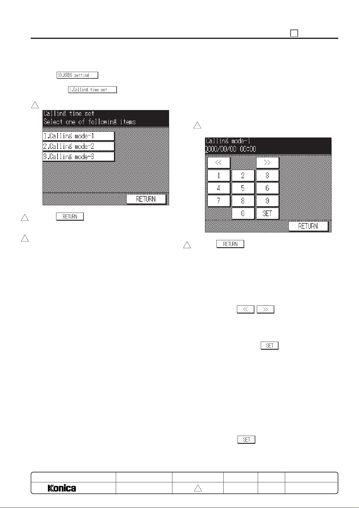
25 ADJUSTMENT
[13] Call setting menu mode
Select the in the 25 mode menu screen to
display the KRDS setting menu screen as an initial screen.
Then select the
set menu screen.
[Calling time set menu screen]
3
Press the key to exit the calling time set menu
3
screen and return to the KRDS setting screen.
Caution: This Host call setting always sets to calling to “Host
3
2”. Therefore, setting of the “Host 2” telephone
number and Host password must be needed in
advance.
to display the calling time
1. Setting designated date calling setting mode
This function sets designated date calling.
(1) Screen selection
Select the [1. Calling mode-1] (Setting designated date
calling setting) in the calling time set menu screen to
display the calling mode-1 (designated date calling) setting screen.
[Calling mode-1 (Designed date calling) setting
3
screen]
Press the key to exit the calling mode-1 (designed
3
date calling) setting screen and return to the calling time set
menu screen.
(2) Entering method
a. Enter year, month, day and time using the numeric
key.
b. The cursor that indicates entering position will be
appeared in the message indication area at line 2.
c. Using the
desired position.
d. If reenter the entered data, press the Stop/clear button
to clear the entered data then enter the data again.
e. Enter year, month, day and time using the numeric
key, then press the
f. Enter year, month, day and time as follows.
• The year is entered by inputting 4-digit in the Christian
era.
• The month and day are entered by inputting 2-digit
number. (Example: 1 is entered as 01.)
• The time is entered using 24 hour clock.
(Example: 1:00p.m. is entered as 13.)
• The minute is entered by inputting 2-digit number.
(Example: 1 is entered as 01.)
• Example:
at 1:00 p.m. of January 15, 1998 →
1998/01/15 13:00
g. Press the
entered and check the entered data.
, key and move the cursor to
key.
key every time data for one item is
MODEL
7040
MANUAL
SERVICE HANDBOOK
REVISED EDITION
5 - 43
3
DATE
Mar. 1999
PAGE
5-43
METHOD
REPLACEMENT
Page 45
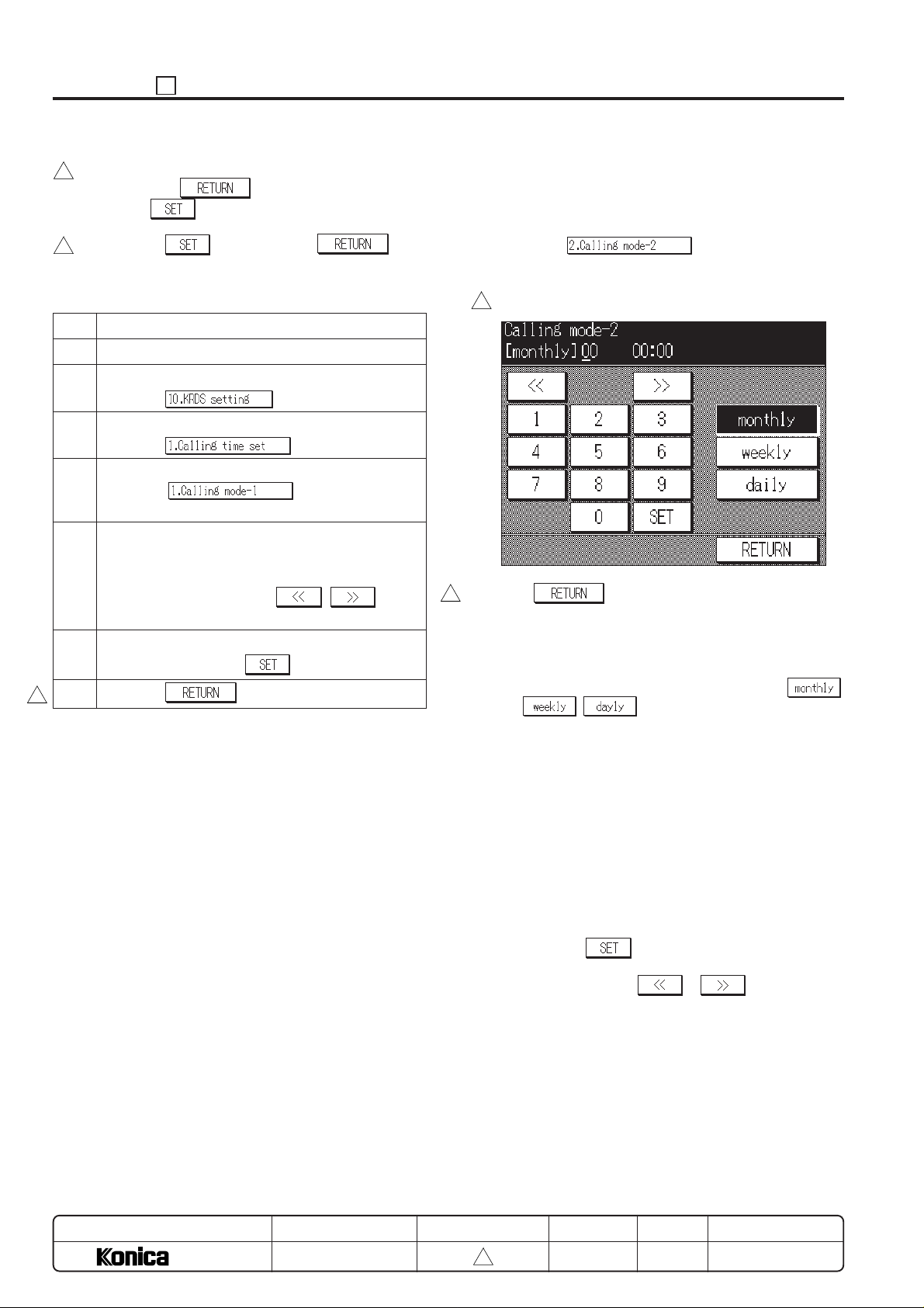
ADJUSTMENT 25
h. The screen will return to the calling time set menu
3
screen if the
ing the
key. In this case, no entered data will
key is pressed without press-
be changed.
i. Press the
3
key, and then the key to
end setting. The screen will return to the calling time
set menu screen.
Step Operation procedure
1 Enter the 25 mode.
2 [25 mode menu screen]
Press the
.
3 [KRDS setting menu screen]
Press the
.
4 [Calling time set menu screen]
Press the (Setting designated
date calling setting).
5 [Calling mode-1 (Designed date calling) setting
screen]
Enter year, month and day using the numeric key on
the screen, then press the
, key to
move the cursor to entering position of time.
6 Enter time and minute using the numeric key on the
screen, then press the key.
7 Press the to end the setting.
3
2. Setting regular time call
The copier will call the host at the regular time specified.
(1) Screen selection
Select the (regular time calling setting) in the calling time set menu screen to display the
calling mode-2 (regular time calling) setting screen.
[Calling mode-2 (regular time calling) setting screen]
3
Press the key to exit the calling mode-2 (regular
3
time calling) setting screen and return to the calling time set
menu screen.
(2) Mode selecting method
a. Select and press the desired mode in the
, keys.
There are three mode type (month, week, day) that
can be set.
b. The current selected mode is high lighted according to
the mode key.
At this time, the setting contents will be appeared in
the message indication area at line 2.
,
MODEL
7040
MANUAL
SERVICE HANDBOOK
(3) Mode setting method
Perform the operation in each mode as follows:
a. Monthly mode
(a) Using the numeric key, enter the day, hour and
minute.
(b) Press the
b. If you wish to change the number of an arbitrary
position, press the
cursor to the desired position and reenter.
c. If reenter the entered data, press the Stop/clear button
to clear the entered data then enter the data again.
REVISED EDITION
5 - 44
3
DATE
Mar. 1999
key to enter the input data.
or key to move the
PAGE
5-44
METHOD
REPLACEMENT
Page 46
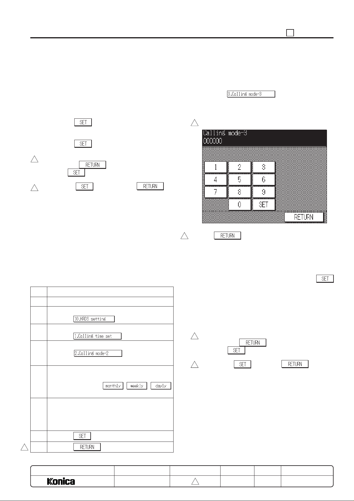
25 ADJUSTMENT
d. Weekly mode
(a) Using the numeric key, enter the day of the week, hour
and minute.
(b) The day of the week is entered using the numeric key
according to the following definitions.
1: Monday 2: Tuesday 3: Wednesday
4: Thursday 5: Friday 6: Saturday
7: Sunday
(c) Press the
key to enter the input data.
e. Daily mode
(a) Using the numeric key, enter the hour and minute.
(b) Press the
key to enter the input data.
f. Common operation
(a) The screen will return to the calling time set menu
3
screen if the
ing the
key. In this case, no entered data will
key is pressed without press-
be changed.
(b) Press the
3
key, and then the key
to end setting. The screen will return to calling time set
menu screen.
(c) Enter the number with the numeric key as follows:
• The month and day are entered by inputting 2-digit
number. (Example: 1 is entered as 01.)
• The time is entered using 24 hour clock.
(Example: 1:00p.m. is entered as 13.)
• The time is entered using 24 hour clock. (Example:
1:00p.m. is entered as 13.)
• Example:
Monthly mode: 10 17:10
Weekly mode: day 17:10
Daily mode: 17:10
Step Operation procedure
1 Enter the 25 mode.
2 [25 mode menu screen]
Press the
.
3 [KRDS setting menu screen]
Press the .
4 [Calling time set menu screen]
Press the (regular time calling
setting).
5 [Calling mode-2 (regular time calling) setting
screen]
Press the any key in , ,
keys.
6 Using the numeric key on the screen, enter the day,
hour and minute.
(Item that can be input differs from depend on the
mode.)
3. Setting regular count call
The copier will call the host at the regular count specified.
(1) Screen selection
Select the (regular transmission interval according to copy count) in the calling time set
menu screen to display the Calling mode-3 (regular count
call) setting screen.
[Calling mode-3 (Regular count call) setting screen]
3
Press the key to exit the Calling mode-3 (Regular
3
count call) setting screen and return to the calling time set
menu screen.
(2) Setting method
a. Using the numeric key on the screen, enter 6-digit
number, regular count value, then press the
key.
b. To reenter the entered data, press the Stop/clear
button to clear the entered data then enter the data
again.
c. The entered numerical value is entered from the
number of 4 digit. The number is displayed while
shifting from right to left.
d. The screen will return to the calling time set menu
3
screen if the
ing the
key. In this case, no entered data will
be changed.
e. Press the
3
the setting. The screen will return to the calling time
set menu screen.
key is pressed without press-
key then the key to end
7 Press the key.
8 Press the to end the setting.
3
MODEL
7040
MANUAL
SERVICE HANDBOOK
REVISED EDITION
5 - 45
3
DATE
Mar. 1999
PAGE
5-45
METHOD
REPLACEMENT
Page 47
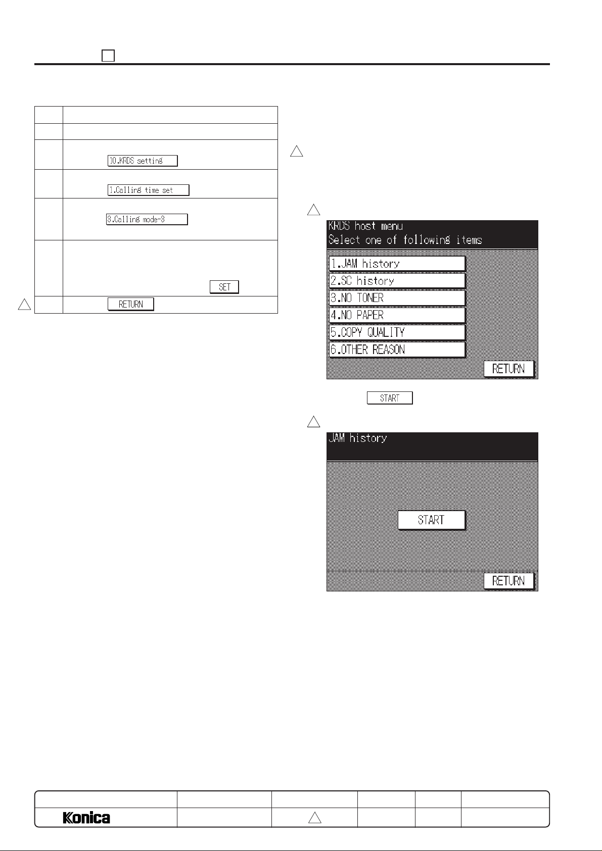
ADJUSTMENT 25
Step Operation procedure
1 Enter the 25 mode.
2 [25 mode menu screen]
Press the
3 [KRDS setting menu screen]
Press the .
4 [Calling time set menu screen]
Press the (regular transmission
interval according to copy count).
5 [Calling mode-3 (Regular count call) setting
screen]
Using the numeric key on the screen, enter number,
regular count value, then press the
6 Press the to end the setting.
3
.
key.
[14] KRDS Host Call
If the machine is connected to a KRDS, it can call the host at
the service center.
a. Select the [JAM history] (JAM-related trouble call), [SC
3
history] (SC-related trouble call), [No TONER], [No PAPER], [COPY QUALITY] (Copy quality-related trouble
call) or [OTHER REASON] (Other call), depending upon
the particular circumstances.
[KRDS host menu screen]
3
b. When the key is pressed, the machine starts
calling the host.
[KRDS host menu execution Screen]
3
MODEL
7040
MANUAL
SERVICE HANDBOOK
Caution: Do not turn OFF the power during communication.
REVISED EDITION
5 - 46
3
DATE
Mar. 1999
PAGE
5-46
METHOD
REPLACEMENT
Page 48
[15] KRDS Data List
1. Common data
3
Classification
1.1
1.2
Common data
2. Sales data
3
Classification
Count data for
sales 1
Limit count and
adjust data
Count data for
sales 2
1.3
1.4
1.5
2.1
2.2
2.3
2.6
2.7
2.8
2.9
2.10
2.11
2.12
3.1
3.2
3.3
3.4
3.5
3.6
3.7
3.8
3.9
3.10
DataNo.
Serial No.
Date and time (local time)
Regular call - time specified
Regular call - count specified
Specified date & time to transmit.
DataNo.
Total copy count
Copy count by copy paper size
EKC copy count
A2/A3 double count
Total copy count start date
EKC password
EKC copy limit
EKC copy limit control
EKC user name
EKC counter all reset
Copy count 2 by EKC copy paper size (A3)
Copy count 3 by EKC copy paper size (B4)
Copy count 4 by EKC copy paper size (A4)
Copy count 5 by EKC copy paper size (B5)
Copy count 6 by EKC copy paper size (A5)
Copy count 7 by EKC copy paper size (B6)
Copy count 8 by EKC copy paper size (8.5x14)
Copy count 9 by EKC copy paper size (8.5x11)
Copy count 10 by EKC copy paper size (Bypass feed)
Copy count 11 by EKC copy paper size (post card)
25 ADJUSTMENT
Data change
Enable/
disable to write
Disable
Data change
Enable/
disable to write
✕
Can be reset
Can be reset
✕
✕
✕
✕
✕
✕
✕
✕
✕
✕
✕
MODEL
7040
MANUAL
SERVICE HANDBOOK
REVISED EDITION
5 - 47
3
DATE
Mar. 1999
PAGE
5-47
METHOD
REPLACEMENT
Page 49
ADJUSTMENT 25
3. Service data
3
Classification
Error count data
Service count data
Process count
data
Limit and adjust
data
Count data for sale
2
Extra count data
No. of SC occurrence by each point
4.1
No. of Jam occurrence by each point
4.2
ADF/RADF paper feed count
5.1
Copy count by each used mode
5.2
Copy count by each part to be replaced
6.1
Drum count
6.2
Regular service count (PM)
6.3
Developing count
6.4
Other process count
6.5
Copy limit by each part to be replaced
7.1
Regular service cycle
7.2
Regular service count start date
7.3
Host password
8.1
Phone number
8.2
Optional machine composition
8.3
ROM version report
8.4
Machine adjust data 2 (Key operator mode)
8.5
Machine adjust data (25 / 36 mode)
8.6
KRDS memory switch data
8.7
User operation setting
8.8
Image processing adjust
8.9
Jam history record (100 occurrences)
9.1
Special part to be replaced copy count
9.2
Optional machine serial number
9.3
Part number to be replaced
9.4
Name of part to be replaced
9.5
Data change
DataNo.
Enable/
disable to write
✕
✕
✕
✕
✕
✕
✕
✕
✕
✕
✕
✕
✕
[16] ISW Setting
Refer to the chapter “ISW”.
MODEL
7040
MANUAL
SERVICE HANDBOOK
REVISED EDITION
5 - 48
3
DATE
Mar. 1999
PAGE
5-48
METHOD
REPLACEMENT
Page 50

Reference
ASCII is 1 byte code specified by ANSI.
It enables to indicate control code, alphabet and number.
25 ADJUSTMENT
Decimal number
0
1
2
3
4
5
6
7
8
9
10
11
12
13
14
Binary number
0000 0000
0000 0001
0000 0010
0000 0011
0000 0100
0000 0101
0000 0110
0000 0111
0000 1000
0000 1001
0000 1010
0000 1011
0000 1100
0000 1101
0000 1110
Hexadecimal number
0
1
2
3
4
5
6
7
8
9
A
B
C
D
E
Character
SH
SX
EX
ET
EQ
AK
BL
BS
HT
LF
HM
CL
CR
S0
Decimal number
32
33
34
35
36
37
38
39
40
41
42
43
44
45
46
Binary number
0010 0000
0010 0001
0010 0010
0010 0011
0010 0100
0010 0101
0010 0110
0010 0111
0010 1000
0010 1001
0010 1010
0010 1011
0010 1100
0010 1101
0010 1110
Hexadecimal number
20
21
22
23
24
25
26
27
28
29
2A
2B
2C
2D
2E
Character
!
”
#
$
%
&
’
(
)
*
+
,
–
.
15
16
17
18
19
20
21
22
23
24
25
26
27
28
29
30
0000 1111
0001 0000
0001 0001
0001 0010
0001 0011
0001 0100
0001 0101
0001 0110
0001 0111
0001 1000
0001 1001
0001 1010
0001 1011
0001 1100
0001 1101
0001 1110
F
10
11
12
13
14
15
16
17
18
19
1A
1B
1C
1D
1E
S1
DE
D1
D2
D3
D4
NK
SN
EB
CN
EM
SB
EC
→
←
↑
47
48
49
50
51
52
53
54
55
56
57
58
59
60
61
62
0010 1111
0011 0000
0011 0001
0011 0010
0011 0011
0011 0100
0011 0101
0011 0110
0011 0111
0011 1000
0011 1001
0011 1010
0011 1011
0011 1100
0011 1101
0011 1110
2F
30
31
32
33
34
35
36
37
38
39
3A
3B
3C
3D
3E
/
0
1
2
3
4
5
6
7
8
9
:
;
<
=
>
31
0001 1111
1F
↓
5 - 49
63
0011 1111
3F
?
Page 51
ADJUSTMENT 25
Decimal number
64
65
66
67
68
69
70
71
72
73
74
75
76
77
78
Binary number
0100 0000
0100 0001
0100 0010
0100 0011
0100 0100
0100 0101
0100 0110
0100 0111
0100 1000
0100 1001
0100 1010
0100 1011
0100 1100
0100 1101
0100 1110
Hexadecimal number
40
41
42
43
44
45
46
47
48
49
4A
4B
4C
4D
4E
Character
@
G
M
Decimal number
32
A
B
C
D
E
F
H
I
J
K
L
N
33
34
35
36
37
38
39
40
41
42
43
44
45
46
Binary number
0110 0000
0110 0001
0110 0010
0110 0011
0110 0100
0110 0101
0110 0110
0110 0111
0110 1000
0110 1001
0110 1010
0110 1011
0110 1100
0110 1101
0110 1110
Hexadecimal number
60
61
62
63
64
65
66
67
68
69
6A
6B
6C
6D
6E
Character
‘
a
b
c
d
e
f
g
h
i
j
k
l
m
n
79
80
81
82
83
84
85
86
87
88
89
90
91
92
93
94
0100 1111
0101 0000
0101 0001
0101 0010
0101 0011
0101 0100
0101 0101
0101 0110
0101 0111
0101 1000
0101 1001
0101 1010
0101 1011
0101 1100
0101 1101
0101 1110
4F
50
51
52
53
54
55
56
57
58
59
5A
5B
5C
5D
5E
O
Q
W
47
P
R
S
T
U
V
X
Y
Z
[
¥
]
^
48
49
50
51
52
53
54
55
56
57
58
59
60
61
62
0110 1111
0111 0000
0111 0001
0111 0010
0111 0011
0111 0100
0111 0101
0111 0110
0111 0111
0111 1000
0111 1001
0111 1010
0111 1011
0111 1100
0111 1101
0111 1110
6F
70
71
72
73
74
75
76
77
78
79
7A
7B
7C
7D
7E
o
p
q
r
s
t
u
v
w
x
y
z
{
|
}
~
95
0101 1111
5F
_
5 - 50
63
0111 1111
7F
Page 52
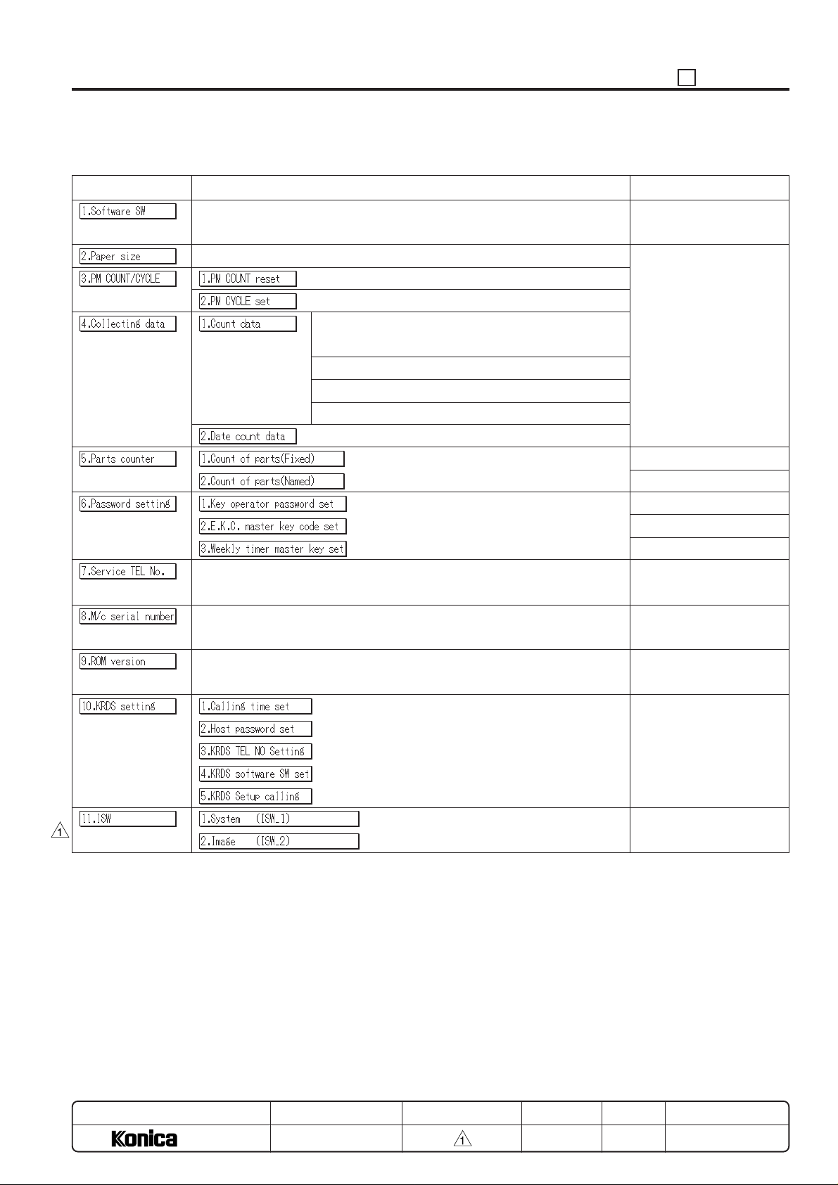
25 Mode Adjustment Item Table
25 ADJUSTMENT
Adjust Item menu
Data collection 1 (by each size)
(RADF paper passage count)
Data collection 2 (JAM occurrence count by each point)
Data collection 3 (Copy count by each mode)
Data collection 4 (SC occurrence count: F code)
(Remarks)
Refer to “List of software
DIP SW”.
49 items
30 items
4-digit
9-digit
4-digit
Telephone & Fax. No. of
service center setting.
Indicates serial No. of main
and each optional unit.
Indicates each ROM version.
MODEL
7040
SERVICE HANDBOOK
REVISED EDITIONMANUAL
5 - 51
DATE
MAR. 1998
Rewriting the system control board program.
PAGE
5-51
METHOD
REPLACEMENT
Page 53
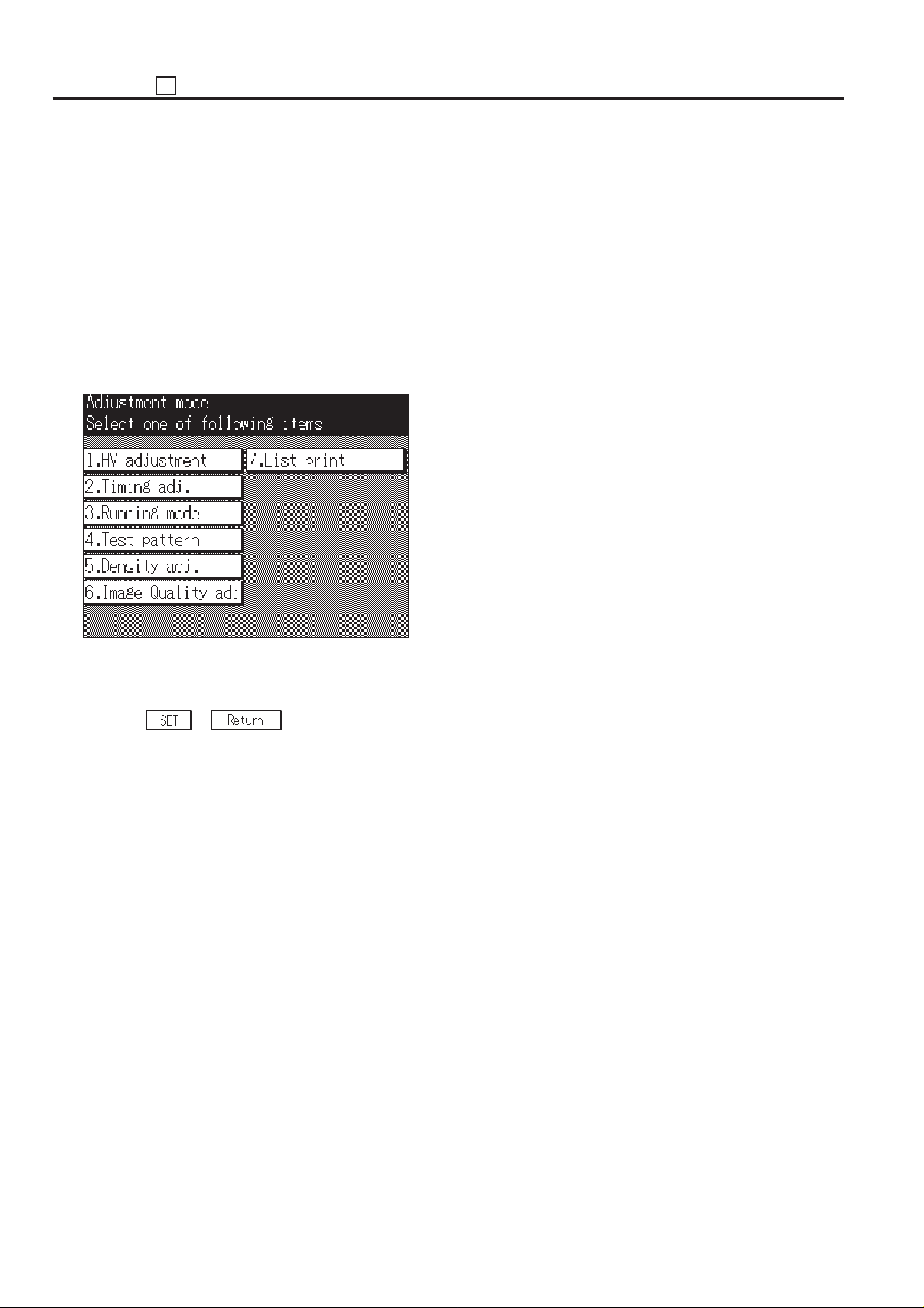
ADJUSTMENT 36
36 MODE
A special operating mode called “36 Mode” has been provided
with this machine. This mode enables adjustment of the
various parts.
[1] Setting Method
1. Turn OFF the SW2 (sub power) when the SW1 (main
power) remains ON.
2. Turn the SW2 (sub power) on while pressing 3 and 6 of the
copy quantity setting buttons.
36 Mode Menu Screen will appear on the LCD screen.
At this time, normal copy operation is not possible.
[36 mode menu screen]
[2] High Voltage Adjustment
1. Charging Corona Current Adjustment
Charging Corona Current Adjustment is inhibited in the field.
2. Transfer Current Adjustment
Transfer Current Adjustment is inhibited in the field.
3. Separation (AC) Voltage Adjustment
Separation (AC) Voltage Adjustment is inhibited in the field.
4. Separation (DC) Current Adjustment
Separation (DC) Current Adjustment is inhibited in the field.
3. Press the desired item key on the LCD screen.
The selected setting screen will appear.
4. Enter data in each setting screen.
5. Press the
6. Turn the SW2 (sub power) off to cancel the 36 mode.
7. New data will be effective after restarted.
or key to end the setting.
5 - 52
Page 54
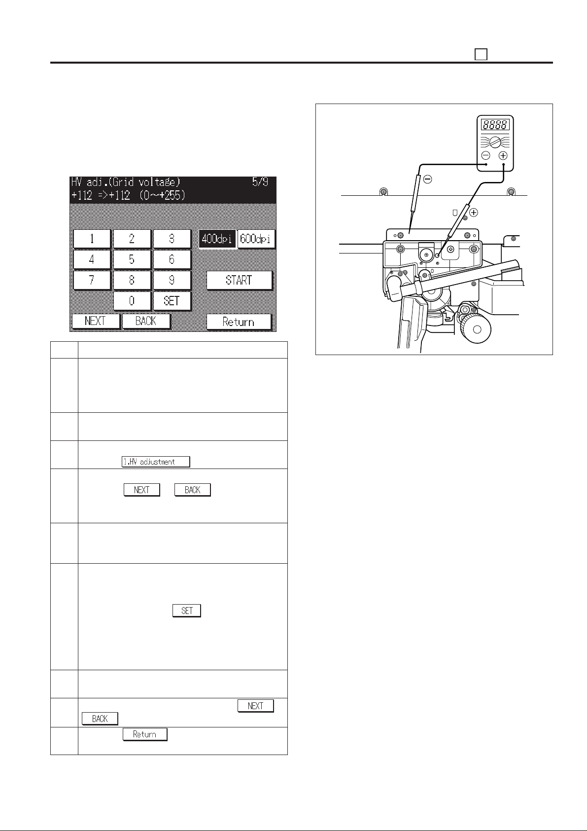
5. Charging Grid Voltage Adjustment
Perform this adjustment when the drum, charging control plate,
High voltage unit 1 or parameter memory board is replaced.
Refer to the “• LIST OF ADJUSTMENT ITEM” (P.5-2) since
there is a prioritization in the adjustment order.
[Grid voltage setting screen]
36 ADJUSTMENT
GND
Charging back
plate
Step Operation procedure
1 Connect the tester as shown Figure.
+: Charging back plate
–: GND (Earth)
Range: 1000 VDC or auto range
2 Fit the door switch jig to the inter lock switch (MS1) for
the front door, then enter the 36 mode.
3 [36 mode menu screen]
Press the
4 [High voltage adjustment screen]
Press the or key until “HV adj.
(Grid voltage)” will appear in the message display
area.
5 [Grid voltage setting screen]
Press the Start print button and check the tester
value.
6 After checking, press the Stop/Clear button.
If the measurement value is different to the standard
value, enter a value using the numeric keys on the
screen, then press the
Standard value:Drum designate value (Indicated on
the flange) ± 5 V
Input range = 0 (lower) ~ 255 (higher)
1 step = 1.6 V
7 Repeat steps 5 and 6 until the grid voltage becomes
the standard value.
8 To adjust another adjustment, press the
key to select the desired adjustment.
9 Press the
menu screen.
key.
key.
key to return to the 36 mode
6. Developing Bias Adjustment
Developing Bias Adjustment is inhibited in the field.
7. Dmax Correction
Normally, this adjustment takes place automatically in the
machine. Because of this adjustment is not required in the field.
or
5 - 53
Page 55
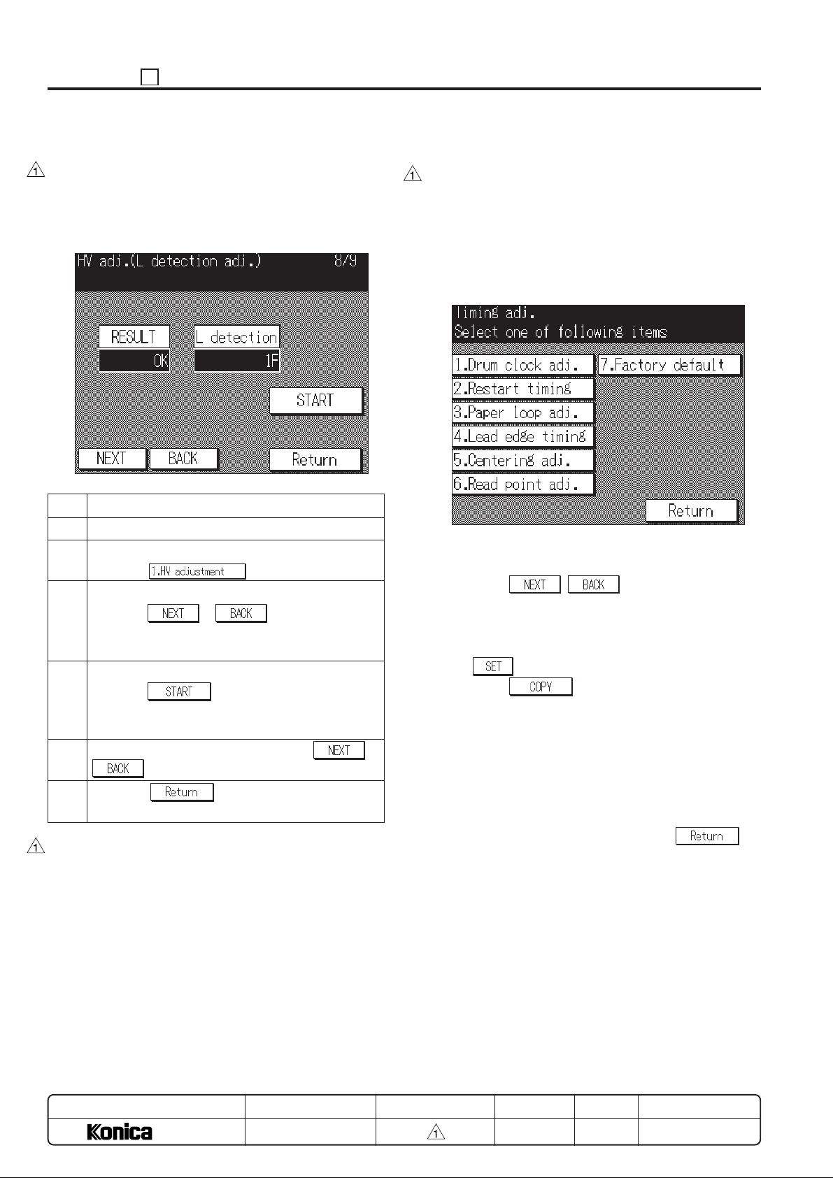
ADJUSTMENT 36
8. L detection Adjustment
Preform this adjustment when installing the main body or
replacing the developer. The developing count is automatically
reset. Refer to the “• LIST OF ADJUSTMENT ITEM” (P. 5-2)
since there is a prioritization in the adjustment order.
[L detection adjustment screen]
Step Operation procedure
1 Enter the 36 mode.
2 [36 mode menu screen]
Press the
3 [High voltage adjustment screen]
Press the or key until “HV adj. (L
detection adj.)” will appear in the message display
area.
4 [L detection adjustment screen]
Press the key, then confirm that the [OK]
is displayed at the “RESULT” and the L detection data
value.
5 To adjust another adjustment, press the
key to select the desired adjustment.
6 Press the key to return to the 36 mode
menu screen.
Caution: When starting the adjustment, check that the devel-
oper is replaced with the new developer. If the
adjustment is performed with the used developer,
the adjustment value becomes mistaken value since
the used developer toner density becomes the
reference value.
key.
or
[3] Timing Adjustment
This function adjusts each timing. Perform the adjustment in
order of the displayed item other than RADF vertical magnification adjustment.
When timing adjustment is performed, use A3 or 11 x 17 size
paper.
(1) Select the [2. Timing adj.] in the 36 mode menu screen.
The timing adjustment menu screen will appear.
[Timing Adjustment menu screen]
(2) Press the item key to be adjusted.
The selected setting screen will appear.
(3) Press the
adjustment item.
The adjustment item name will appear in the message
area on each item screen.
(4) Enter data from the numeric key on the screen, then press
the
(5) Press the
then make a test copy. (except for [7. Factory default])
(6) Press the C button while pressing the P button to return to
the adjustment screen.
(7) If the output (test copy image) is different to the standard
value, enter setting value using the numeric keys and
make a test copy.
If the output (test copy image) is in the standard value,
adjust the next adjustment item.
(8) After adjustment is completed, press the
to return to the timing adjustment screen.
key to enter the data that has been entered.
, key to select the desired
key to return to the basic screen,
key
9. Toner automatic supply
Normally, this adjustment takes place automatically in the
machine. Because of this adjustment is not required in the field.
MODEL
7040
SERVICE HANDBOOK
REVISED EDITIONMANUAL
5 - 54
DA TE
MAR. 1998
PAGE
5-54
METHOD
REPLACEMENT
Page 56
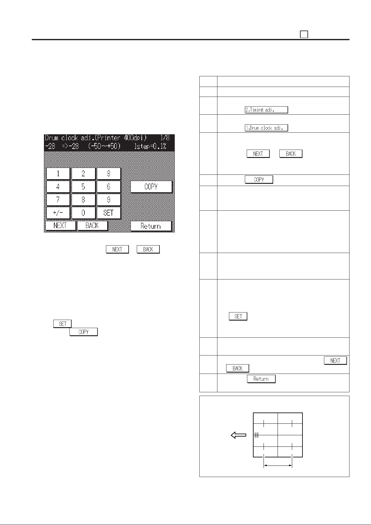
36 ADJUSTMENT
1. Vertical/Horizontal magnification adjustment
Adjust the vertical magnification at the zoom mode.
(1) Select the [2. Timing adj.] in the 36 mode menu screen,
then the timing adjustment menu screen will appear.
Select the [1. Drum clock adj.] on this screen, then the
vertical/horizontal magnification adjustment screen will
appear.
[Vertical/Horizontal magnification (Drum clock) adjustment screen (Example: Printer (400dpi))]
This adjustment has the following items. These can be
selected by pressing the
· Printer vertical magnification adjustment (400dpi)
· Printer vertical magnification adjustment (600dpi)
· Platen vertical magnification adjustment
· Platen horizontal magnification adjustment
· RADF (50%) vertical magnification adjustment
· RADF (100%) vertical magnification adjustment
· RADF (200%) vertical magnification adjustment
· RADF (400%) vertical magnification adjustment
(2) Enter data from the numeric key on the screen, then press
the
(3) Press the
key to enter the data that has been entered.
key to return to the basic screen,
then make a test copy.
(4) Press the C button while pressing the P button to return to
the Vertical/Horizontal magnification adjustment screen.
(5) If the output (test copy image) is different to the standard
value, enter setting value using the numeric keys and
make a test copy.
If the output (test copy image) is within the standard value,
adjust the next adjustment item.
or key.
a. printer system vertical magnification adjustment
Step Operation procedure
1 Enter the 36 mode.
2 [ 36 mode menu screen ]
Press the
key.
3 [Timing adjustment menu screen]
Press the key.
4 [Vertical/Horizontal magnification (Drum clock)
adjustment screen]
Press the or key until “Printer
(400dpi)” or “Printer (600dpi)” will appear in the
message display area.
5 Press the key.
6 [Basic screen]
Select A3 or 11 x 17 size paper, then press the Start
print button to print the SGU pattern.
7 Measure the vertical magnification of the output
paper.
Standard value:
± 0.5% max (life size)
Within about ± 1 mm with respect to 206 mm.
8 Press the C button while pressing the P button to
return to the vertical/horizontal magnification (Drum
clock) adjustment screen.
9 [Vertical/Horizontal magnification (Drum clock)
adjustment screen]
If the vertical magnification is different to the standard
value, enter a value from the numeric key, then press
the
key to store the adjustment value.
Input range = –50 (reduction) ~ +50 (enlargement)
1 step = 0.1%
10 Repeat steps 5 to 9 until the vertical magnification
becomes the standard value.
11 To adjust another adjustment item, press the
or key to select the desired adjustment.
12 Press the
key to return to the timing
adjustment menu screen.
Standard value: ±0.5% max (life size)
Within about ± 1.0 mm with respect to 206 mm.
5 - 55
206
Vertical magnification
Page 57

ADJUSTMENT 36
b. Platen vertical magnification adjustment
Step Operation procedure
1 Enter the 36 mode.
2 [36 mode menu screen]
Press the
3 [Timing adjustment menu screen]
Press the key.
4 [Vertical/Horizontal magnification (Drum clock)
adjustment screen]
Press the or key until “Scanner”
will appear in the message display area.
5 Press the key.
6 [Basic screen]
Set the new pyramid chart on the original glass and
select A3 or 11 x 17 size paper. Then press the Start
print button to make a test copy.
7 Measure the vertical magnification of the output paper.
Standard value:
± 0.5% max (life size)
Within about ± 1 mm with respect to 200 mm.
8 Press the C button while pressing the P button to
return to the vertical/horizontal magnification adjust-
ment screen.
9 [Vertical/Horizontal magnification (Drum clock)
adjustment screen]
If the vertical magnification is different to the standard
value, enter a value from the numeric key, then press
the
Input range = –31 (reduction) ~ +31 (enlargement)
10 Repeat steps 5 to 9 until the vertical magnification
becomes the standard value.
11 To adjust another adjustment item, press the
or key to select the desired adjustment.
key to store the adjustment value.
1 step = 0.05 %
key.
c. Platen horizontal magnification adjustment
Step Operation procedure
1 Enter the 36 mode.
2 [36 mode menu screen]
Press the
3 [Timing adjustment menu screen]
Press the
4 [Vertical/Horizontal magnification (Drum clock)
adjustment screen]
Press the
appear in the message display area.
5 Press the
6 [Basic screen]
Set the new pyramid chart on the original glass and
select A3 or 11 x 17 size paper. Then press the Start
print button to make a test copy.
7 Measure the horizontal magnification of the output paper.
Standard value:
± 0.5% max (life size)
Within about ± 1 mm with respect to 200 mm.
8 Press the C button while pressing the P button to
return to the vertical/horizontal magnification adjust-
ment screen.
9 [Vertical/Horizontal magnification (Drum clock)
adjustment screen]
If the horizontal magnification is different to the stand-
ard value, enter a value from the numeric key, then
press the
Input range = –10 (reduction) ~ +10 (enlargement)
10 Repeat steps 5 to 9 until the vertical magnification
becomes the standard value.
11 To adjust another adjustment item, press the
or key to select the desired adjustment.
12 Press the key to return to the timing
adjustment menu screen.
or key until “Platen” will
key to store the adjustment value.
1 step = 0.1 %
key.
key.
key.
12 Press the
adjustment menu screen.
Standard value: ± 0.5% max (life size)
Within about ± 1.0 mm with respect to 200 mm.
MODEL
key to return to the timing
7040
SERVICE HANDBOOK
REVISED EDITIONMANUAL
5 - 56
Standard value: ± 0.5% max (life size)
Caution: The result of the platen horizontal magnification
Within about ± 1.0 mm with respect to 200 mm.
adjustment is reflected all scanner read images
(platen, RADF).
DA TE
MAR. 1998
PAGE
5-56
METHOD
REPLACEMENT
Page 58
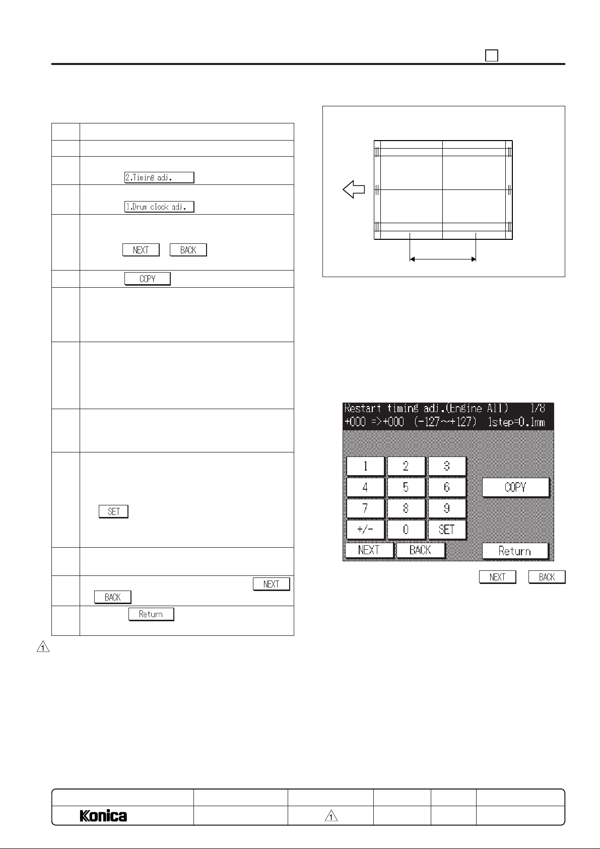
36 ADJUSTMENT
d. RADF vertical magnification adjustment
Step Operation procedure
1 Enter the 36 mode.
2 [36 mode menu screen]
Press the key.
3 [Timing adjustment menu screen]
Press the key.
4 [Vertical/Horizontal magnification (Drum clock)
adjustment screen]
Press the or key until “RADF/100”
will appear in the message display area.
5 Press the key.
6 [Basic screen]
Set the ADF adjustment chart on the RADF and
select A3 or 11 x 17 size paper. Then press the Start
print button to make a test copy.
7 Measure the vertical magnification of the output
paper.
Standard value:
± 1.0% max (life size)
Within about ± 2.0 mm with respect to 200 mm.
8 Press the C button while pressing the P button to
return to the vertical/horizontal magnification adjust-
ment screen.
9 [Vertical/Horizontal magnification (Drum clock)
adjustment screen]
If the vertical magnification is different to the standard
value, enter a value from the numeric key, then press
the
Input range = –20 (reduction) ~ +20 (enlargement)
10 Repeat steps 5 to 9 until the vertical magnification
becomes the standard value.
11 To adjust another adjustment item, press the
or key to select the desired adjustment.
12 Press the key to return to the timing
adjustment menu screen.
Caution: The RADF vertical magnification adjustment is per-
formed in order of 100%, 50%, 200%, 400%.
key to store the adjustment value.
1 step = 0.1 %
Standard value: ± 1.0% max (life size)
Within about ± 2.0 mm with respect to 200 mm.
Vertical
magnification
200
2. Restart timing adjustment
To adjust the restart timing.
Select the [2. Timing adj.] in the 36 mode menu screen, then the
timing adjustment menu screen will appear.
Select the [2. Restart timing] on this screen, then the restart
timing adjustment screen will appear.
This adjustment has the following kinds of items.
[Restart Timing Adjustment Screen (Example: engine)]
These can be selected by pressing the
key.
a. Engine All (item other than RADF)
b. Main body lower tray
c. DB1
d. DB2
e. DB 3 (for DB-208 is installed)
f. By-pass
g. ADU
h. RADF (front side)
i. RADF (back side)
or
MODEL
7040
SERVICE HANDBOOK
REVISED EDITIONMANUAL
5 - 57
DATE
MAR. 1998
PAGE
5-57
METHOD
REPLACEMENT
Page 59
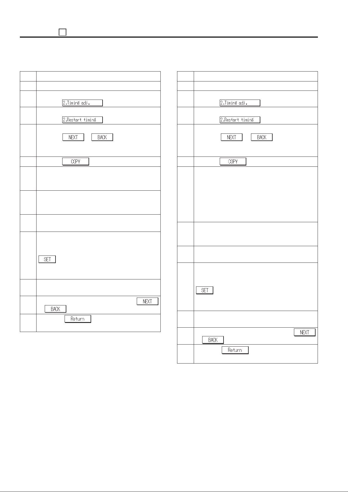
ADJUSTMENT 36
(1)Engine restart timing adjustment
Step Operation procedure
1 Enter the 36 mode.
2 [36 mode menu screen]
Press the
3 [Timing adjustment menu screen]
Press the key.
4 [Restart timing adjustment screen]
Press the
adjustment item will appear in the message display
area.
5 Press the
6 [Basic screen]
Select A3 or 11 x 17 size paper and press the Start
print button to print the SGU pattern.
7 Check the restart (leading edge) timing of the output
paper.
Standard value: Within ± 2.0 mm
8 Press the C button while pressing the P button to
return to the restart timing adjustment screen.
9 [Restart timing adjustment screen]
If the restart timing is different to the standard value,
enter a value from the numeric key, then press the
key to store the adjustment value.
Input range = –127(slow) ~ +127 (fast)
10 Repeat steps 5 to 9 until the restart timing becomes
the standard value.
11 To adjust another adjustment item, press the
or key to select the desired adjustment.
12 Press the key to return to the timing
adjustment menu screen.
or key until the desire
1 step = 0.1 mm
key.
key.
(2)RADF restart timing adjustment
Step Operation procedure
1 Enter the 36 mode.
2 [36 mode menu screen]
Press the
3 [Timing adjustment menu screen]
Press the key.
4 [Restart timing adjustment screen]
Press the
(surface)” or “(RADF/back)” will appear in the mes-
sage display area.
5 Press the
6 [Basic screen]
Set the ADF adjustment chart on the RADF and
select A3 or 11 x 17 size paper. Then press the Start
print button to make a test copy.
* Adjust the “RADF/back”, then make a test copy in
2-1 mode and check the restart timing of 2nd output
paper.
7 Check the restart (leading edge) timing of the output
paper.
Standard value: Within ± 3.0 mm (life size)
8 Press the C button while pressing the P button to
return to the restart timing adjustment screen.
9 [Restart timing adjustment screen]
If the restart timing is different to the standard value,
enter a value from the numeric key, then press the
key to store the adjustment value.
Input range = –50 (slow) ~ +50 (fast)
10 Repeat steps 5 to 9 until the restart timing becomes
the standard value.
11 To adjust another adjustment item, press the
or key to select the desired adjustment.
or key until “(RADF/
1 step = 0.1 mm
key.
key.
5 - 58
12 Press the key to return to the timing
adjustment menu screen.
Page 60
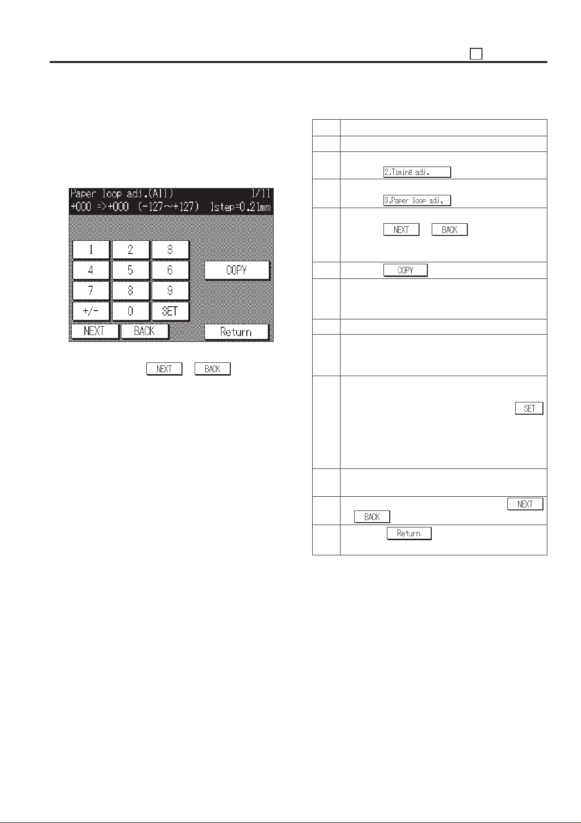
36 ADJUSTMENT
3. Paper feed loop amount adjustment
Adjust the loop amount for each tray.
Select the [2. Timing adj.] in the 36 mode menu screen, then the
timing adjustment menu screen will appear.
Select the [3. Paper loop adj.] on this screen, then the paper
feed loop amount adjustment screen will appear.
[Paper feed loop amount adjustment screen (All)]
This adjustment has the following kinds of items. These can be
selected by pressing the
a. All
b. ADU (small size: *1)
c. ADU (large size: *2)
d. Main body lower tray (small size: *3)
e. Main body lower tray (large size: *4)
f. DB
g. By-pass (plain paper)
h. By-pass (thick paper)
i. ADU
j. RADF (front side)
k. RADF (back side)
*1: A5, B6R, B5, 5.5x8.5
*2: Except for A5, B6R, B5, 5.5x8.5
*3: Except for F4R, A3, B4, 8.5x14, 11x17
*4: F4R, A3, B4, 8.5x14, 11x17
or key.
(1)Paper feed loop amount adjustment for engine
Step Operation procedure
1 Enter the 36 mode.
2 [36 mode menu screen]
Press the
3 [Timing adjustment menu screen]
Press the key.
4 [Paper feed loop amount adjustment screen]
Press the
adjustment item will appear in the message display
area.
5 Press the
6 [Basic screen]
Select A3 or 11 x 17 size paper, then press the Start
print button to print the SGU pattern.
7 Check the paper feed loop amount.
8 Press the C button while pressing the P button to
return to the paper feed loop amount adjustment
screen.
9 [Paper feed loop amount adjustment screen]
If the paper feed loop amount is not proper, enter a
value from the numeric key, then press the
key to store the adjustment value.
Input range = –127 (small) 00 (standard) ~ +127
10 Repeat steps 5 to 9 until the paper feed loop amount
is appropriate.
11 To adjust another adjustment item, press the
or key to select the desired adjustment.
12 Press the key to return to the timing
adjustment menu screen.
or key until the desire
(large)
1 step = 0.21 mm
key.
key.
5 - 59
Page 61
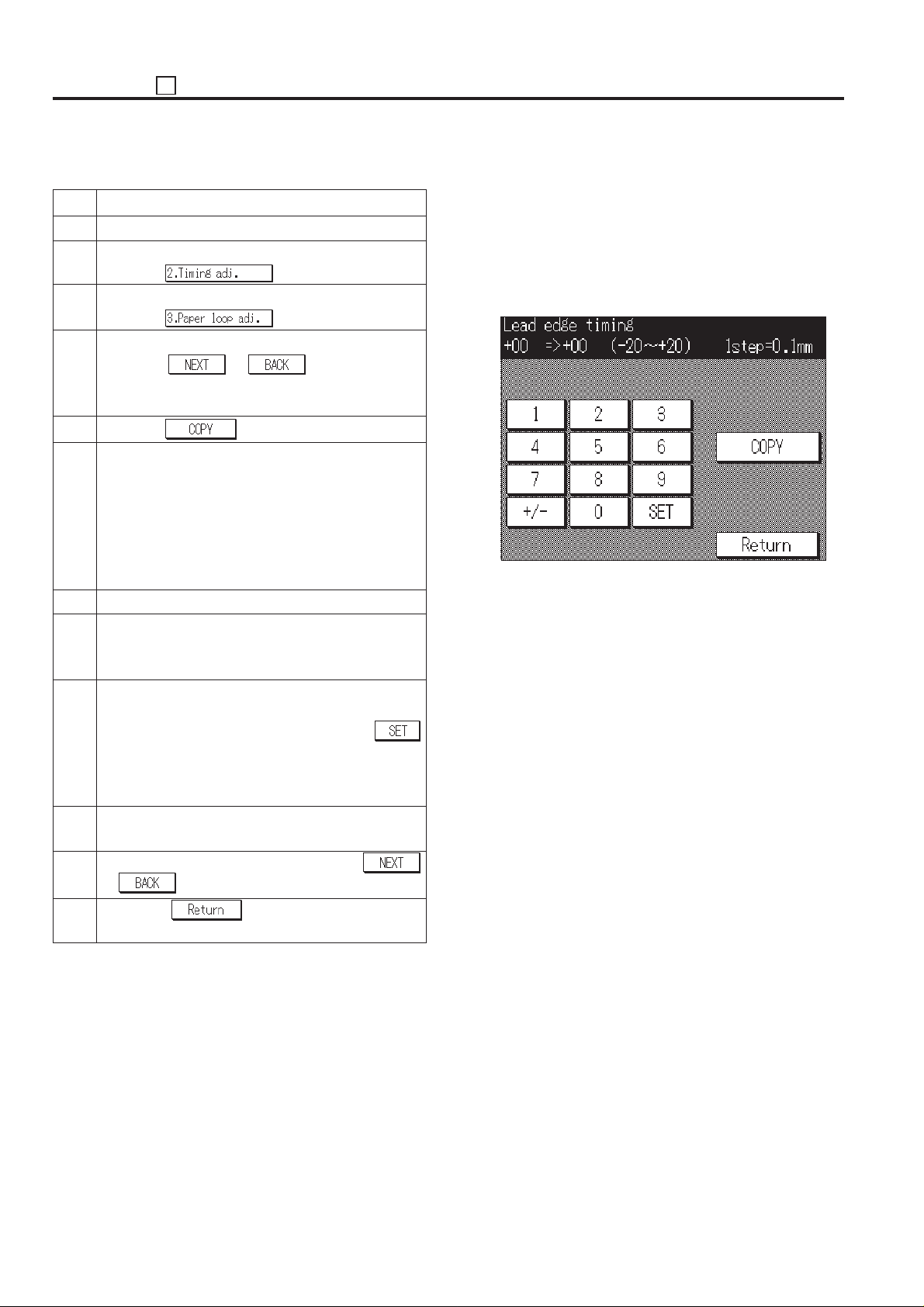
ADJUSTMENT 36
(2)Paper feed loop amount adjustment for RADF
Step Operation procedure
1 Enter the 36 mode.
2 [36 mode menu screen]
Press the
3 [Timing adjustment menu screen]
Press the key.
4 [Paper feed loop amount adjustment screen]
Press the
surface)” or “(RADF/back)” will appear in the mes-
sage display area.
5 Press the
6 [Basic screen]
Set the ADF adjustment chart on the RADF and
select A3 or 11 x 17 size paper, then press the Start
print button to make a test copy.
* Adjust the “RADF/back”, then make a test copy in
2-1 mode and check the loop amount of 2nd
outputted paper.
7 Check the paper feed loop amount.
8 Press the C button while pressing the P button to
return to the paper feed loop amount adjustment
screen.
9 [Paper feed loop amount adjustment screen]
If the paper feed loop amount is not proper, enter a
value from the numeric key, then press the
key to store the adjustment value.
Input range = –10 (small) 00 (standard) ~ +10 (large)
10 Repeat steps 5 to 9 until the paper feed loop amount
is appropriate.
11 To adjust another adjustment item, press the
or key to select the desired adjustment.
or key until “(RADF/
1 step = 0.5 mm
key.
key.
4. Leading edge original erasure adjustment
Adjust the leading edge original erasure (leading edge blank
cut) amount.
Select the [2. Timing adj.] in the 36 mode menu screen, then the
timing adjustment menu screen will appear.
Select the [4. Lead edge timing] on this screen, then the leading
edge original erasure amount adjustment screen will appear.
[Leading edge original erasure adjustment screen]
12 Press the key to return to the timing
adjustment menu screen.
5 - 60
Page 62
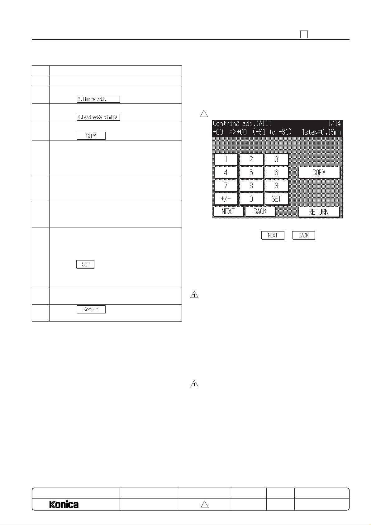
36 ADJUSTMENT
Step Operation procedure
1 Enter the 36 mode.
2 [36 mode menu screen]
Press the
3 [Timing adjustment menu screen]
Press the key.
4 [Leading edge original erasure adjustment screen]
Press the key.
5 [Basic screen]
Set the new pyramid chart on the original glass and
select A3 or 11 x 17 size paper, then press the Start
print button to make a test copy.
6 Measure the leading edge original erasure amount of
the output paper.
Standard value: Within 3.0 mm
7 Press the C button while pressing the P button to
return to the leading edge original erasure amount
adjustment screen.
8 [Leading edge original erasure amount adjust-
ment screen]
If the leading edge original erasure amount is not
proper, enter a value from the numeric key, then
press the
Input range = –20 (small) ~ +20 (large)
9 Repeat steps 4 to 8 until the leading edge original
erasure amount becomes the standard value.
10 Press the key to return to timing adjust-
ment menu screen.
key to store the adjustment value.
1 step = 0.1 mm
key.
5. Centering adjustment
Adjusts the mis-centering for paper feed direction.
Select the [2. Timing adj.] in the 36 mode menu screen, then the
timing adjustment menu screen will appear.
Select the [5. Centering adj.] on this screen, then the centering
adjustment screen will appear.
[Centering adjustment screen (Example: All)]
3
This adjustment has the following kinds of items. These can be
selected by pressing the
a. All
b. Main body lower tray
c. DB1
d. DB2
e. DB3 (for DB-208 is installed)
f. By-pass
g. ADU (Co/L/M/S/SS: *1, *2)
h. Platen (*3)
i. RADF (side 1)
j. RADF (side 2)
*1: ADU centering adjustment can be taken place for each
paper size. (L/M/S/SS)
L: A3, B4, 11x17, 8.5x14
M: A4R, B5R, 8.5x11R
S: A4, B5, 8.5x11
SS:A5R, 5.5x8.5R
*2: ADU centering adjustment for each paper size is the
offset adjustment from the ADU (collective).
*3: The adjustment of “i”, “j”, “k” is performed after “a” to “g”
are finished.
or key.
MODEL
7040
MANUAL
SERVICE HANDBOOK
REVISED EDITION
5 - 61
3
DATE
Mar. 1999
PAGE
5-61
METHOD
REPLACEMENT
Page 63
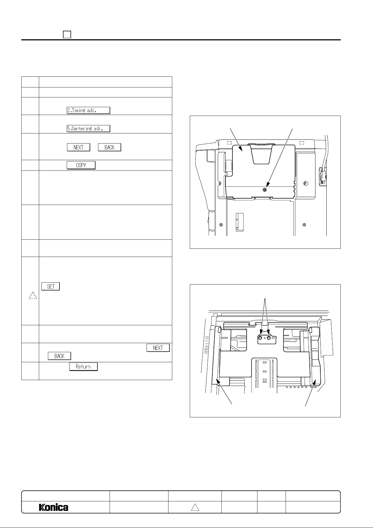
ADJUSTMENT 36
(1)Each tray centering adjustment
Step Operation procedure
1 Enter the 36 mode.
2 [ 36 mode menu screen ]
Press the
key.
3 [Timing adjustment menu screen]
Press the key.
4 [Centering adjustment Screen]
Press the
or key until the desire
tray will appear in the message display area
5 Press the key.
6 [Basic screen]
Set A3 or 11 x 17 size paper in the tray to be adjusted
and select this tray. Then press the Start print button
to print the SGU pattern.
7 Fold the output (SGU pattern) at the center in the
paper feed direction, and check that the left and right
line coincide exactly.
Standard value: Within ± 2 mm
8 Press the C button while pressing the P button to
return to the centering adjustment screen.
9 [Centering adjustment screen]
If the mis-centering is more than standard value,
enter a value from the numeric key, then press the
key to store the adjustment value.
Input range = –31 (inward direction of the center
3
line) ~ + 31 (rear direction of the center
line)
1 step = 0.13 mm
10 Repeat steps 5 to 9 until the mis-centering is within
standard value. (*1)
11 To adjust another adjustment item, press the
or key to select the desired adjustment.
*1: If centering is not within specification after adjusting data
mechanical adjustment is possible.
1. By-pass
Loosen the centering adjustment screw (TP screw) on the
back side of the by-pass tray, then slide the centering
restriction guide (front and rear) and adjust the centering.
By-pass tray
Machine right side
Centering adjustment screw
2. Universal tray
Loosen the two centering adjustment screws (bind screw)
on the tray center and adjusts the centering.
Centering adjustment screws
12 Press the key to return to the timing
adjustment menu screen.
MODEL
7040
MANUAL
SERVICE HANDBOOK
REVISED EDITION
5 - 62
3
Side guide (rear)
DATE
Mar. 1999
PAGE
5-62
Side guide (front)
METHOD
REPLACEMENT
Page 64
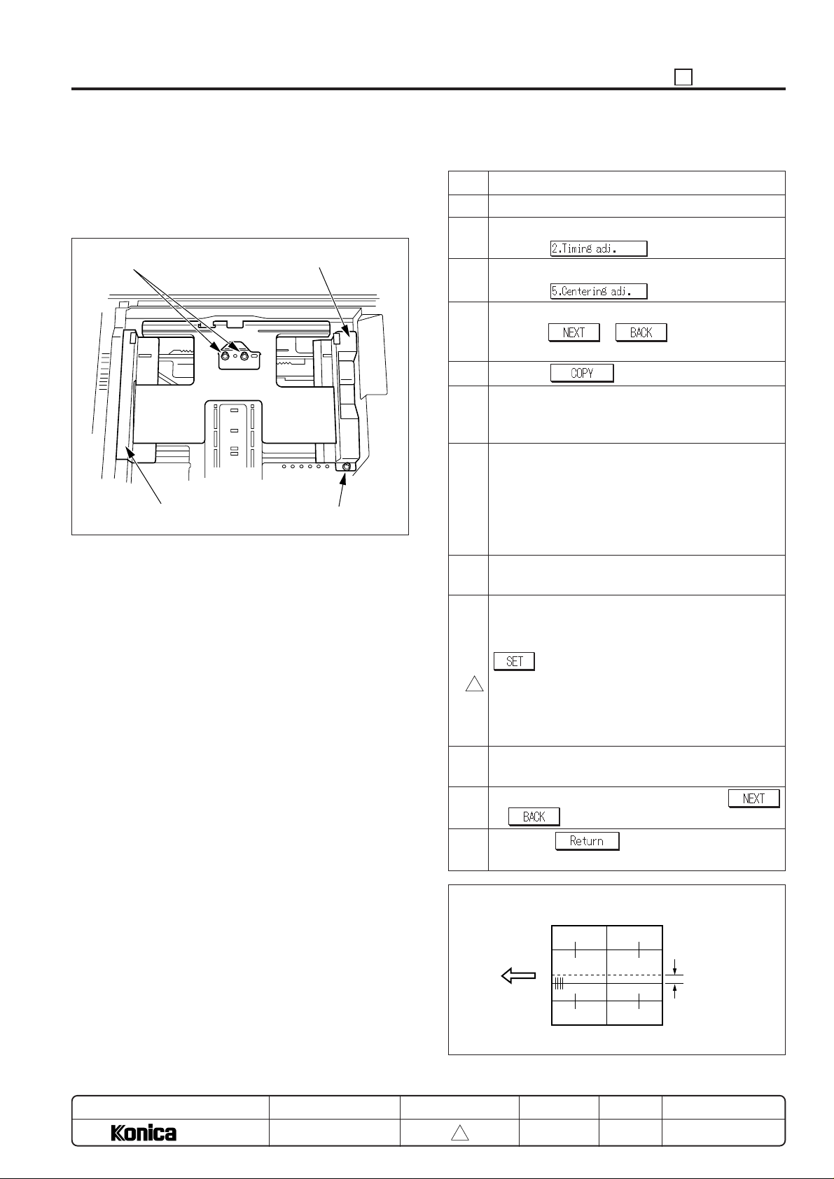
36 ADJUSTMENT
3. Tray (fixed tray)
Loosen the one set screw (TP screw) holding the side
guide (front), then loosen the two centering adjustment
screws (bind screw) on the tray center and adjusts the
centering.
Centering adjustment screws
Side guide (rear)
Side guide (front)
Set screw
(2) ADU centering adjustment
Step Operation procedure
1 Enter the 36 mode.
2 [36 mode menu screen]
Press the
key.
3 [Timing adjustment menu screen]
Press the key.
4 [Centering adjustment screen]
Press the or key until “(ADU)” will
appear in the message display area.
5 Press the key.
6 [Basic screen]
Select copy mode to 1-2 mode, then press the Start
print button to print the SGU pattern.
7 Fold the output (SGU pattern) at the center in the
paper feed direction, and check that the left and right
line coincide exactly.
Standard value:
Front side ; Within ± 3 mm
Back side ; Within ± 3 mm
8 Press the C button while pressing the P button to
return to the centering adjustment screen.
9 [Centering adjustment screen]
If the mis-centering is more than standard value,
enter a value from the numeric key, then press the
key to store the adjustment value.
Input range = –31 (inward direction of the center
3
line) ~ + 31 (rear direction of the center
line)
1 step = 0.13 mm
10 Repeat steps 5 to 9 until the mis-centering is within
standard value for each paper size.
11 To adjust another adjustment item, press the
or key to select the desired adjustment.
MODEL
7040
MANUAL
SERVICE HANDBOOK
12 Press the key to return to the timing
adjustment menu screen.
Standard value: Within 3.0 mm (life size)
Lengthwise
direction
REVISED EDITION
5 - 63
3
DATE
Mar. 1999
PAGE
5-63
Mis-centering amount
between front side
and back side.
METHOD
REPLACEMENT
Page 65
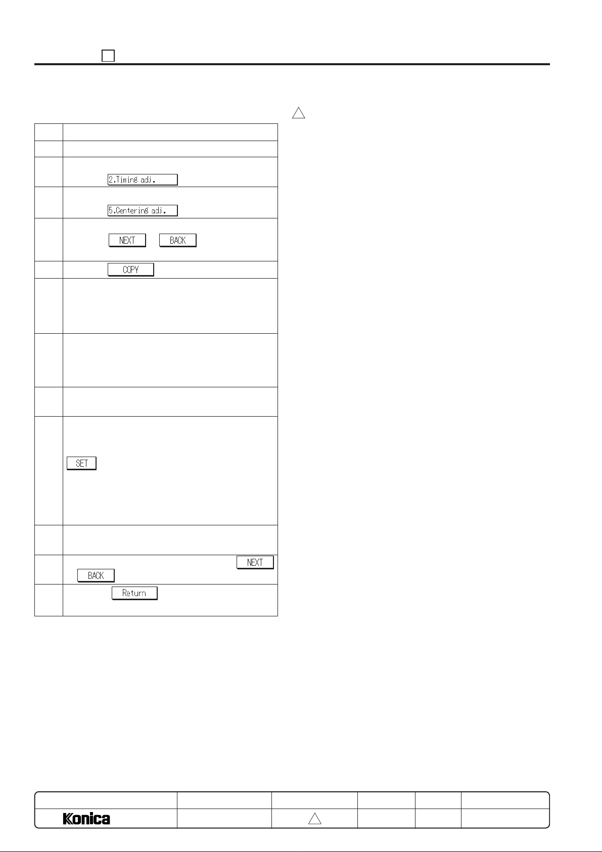
ADJUSTMENT 36
(3)Platen centering adjustment
Step Operation procedure
1 Enter the 36 mode.
2 [36 mode menu screen]
Press the
3 [Timing adjustment menu screen]
Press the key.
4 [Centering adjustment screen]
Press the or key until “(Platen)”
will appear in the message display area.
5 Press the key.
6 [Basic screen]
Set the new pyramid chart on the original glass and
select A3 or 11 x 17 size paper, then press the Start
print button to make a test copy.
7 Fold the output (test copy) at the center in the paper
feed direction, and check that the left and right line
coincide exactly.
Standard value: Within ± 2 mm
8 Press the C button while pressing the P button to
return to the centering adjustment screen.
9 [Centering adjustment screen]
If the mis-centering is more than standard value,
enter a value from the numeric key, then press the
key to store the adjustment value.
Input range = –74 (inward direction of the center
line) ~ + 74 (rear direction of the center
line)
1 step = 0.06 mm
10 Repeat steps 5 to 9 until the mis-centering is within
standard value.
11 To adjust another adjustment item, press the
or key to select the desired adjustment.
key.
3
12 Press the key to return to the timing
adjustment menu screen.
MODEL
7040
MANUAL
SERVICE HANDBOOK
REVISED EDITION
5 - 64
3
DATE
Mar. 1999
PAGE
5-64
METHOD
REPLACEMENT
Page 66
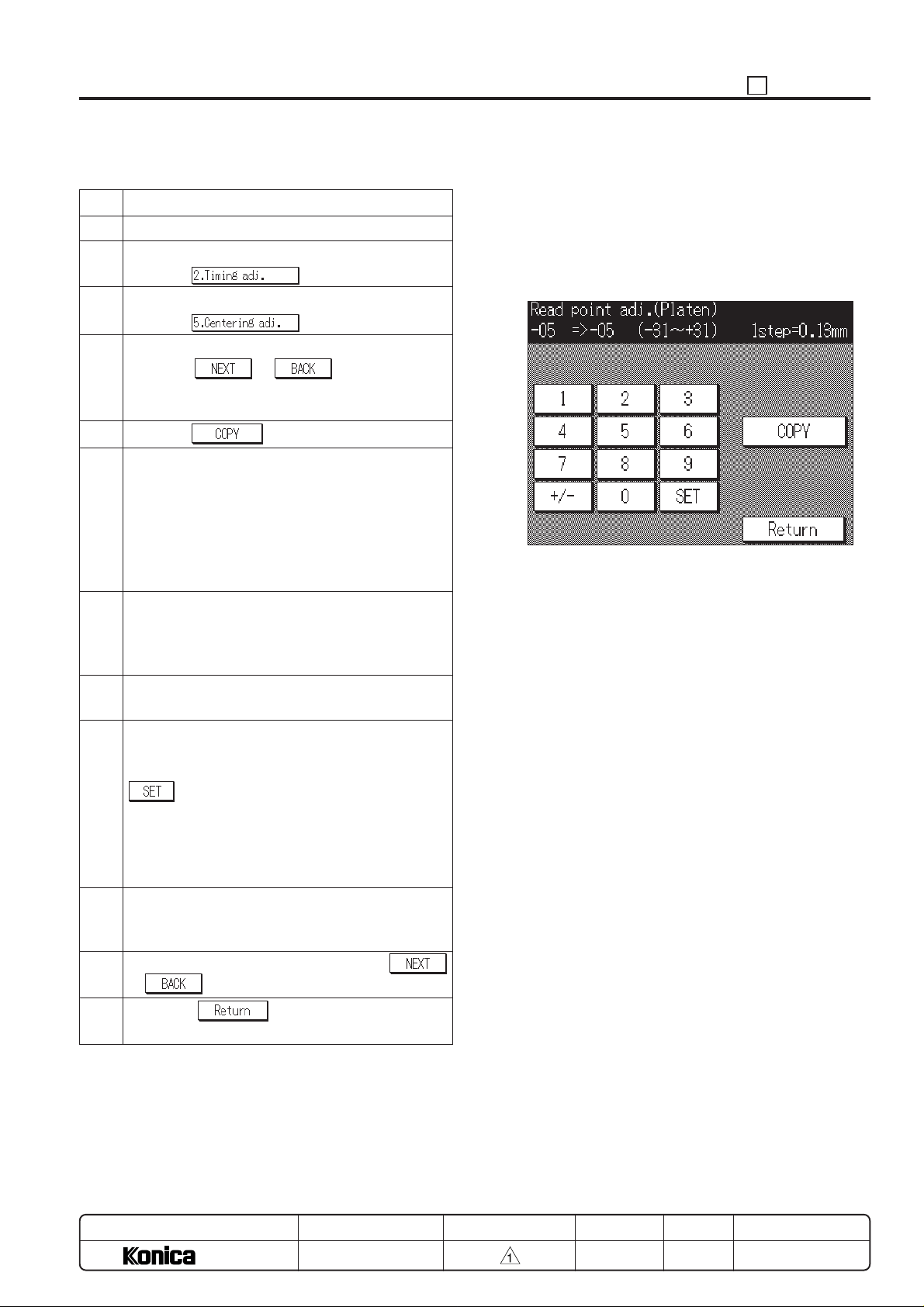
(4) RADF centering adjustment 6. Image read point adjustment
Step Operation procedure
1 Enter the 36 mode.
2 [36 mode menu screen]
Press the
3 [Timing adjustment menu screen]
Press the key.
4 [Centering adjustment screen]
Press the or key until “(RADF/
surface)” or “(RADF/back) will appear in the message
display area.
5 Press the key.
6 [Basic screen]
Set the ADF adjustment chart on the RADF and
select A3 or 11 x 17 size paper, then press the Start
print button to make a test copy.
* Adjust the “RADF/back”, then make a test copy in
2-1 mode and check the loop amount of 2nd
outputted paper.
7 Fold the output (test copy) at the center in the paper
feed direction, and check that the left and right line
coincide exactly.
Standard value: Within ± 3 mm
8 Press the C button while pressing the P button to
return to the centering adjustment screen.
9 [Centering adjustment screen]
If the mis-centering is more than standard value,
enter a value from the numeric key, then press the
key to store the adjustment value.
Input range = –74 (inward direction of the center
line) ~ + 74 (rear direction of the center
line)
1 step = 0.06 mm
10 Repeat steps 5 to 9 until the mis-centering is within
standard value for each adjustment (“RADF/surface”
and “RADF/back”).
11 To adjust another adjustment item, press the
or key to select the desired adjustment.
key.
Adjusts the image read point.
Select the [2. Timing adj.] in the 36 mode menu screen, then the
timing adjustment menu screen will appear.
Select the [6. Read point adj.] on this screen, then the centering
adjustment screen will appear.
[Image read point adjustment screen]
36 ADJUSTMENT
12 Press the
adjustment menu screen.
MODEL
7040
key to return to the timing
SERVICE HANDBOOK
REVISED EDITIONMANUAL
5 - 65
DATE
MAR. 1998
PAGE
5-65
METHOD
REPLACEMENT
Page 67
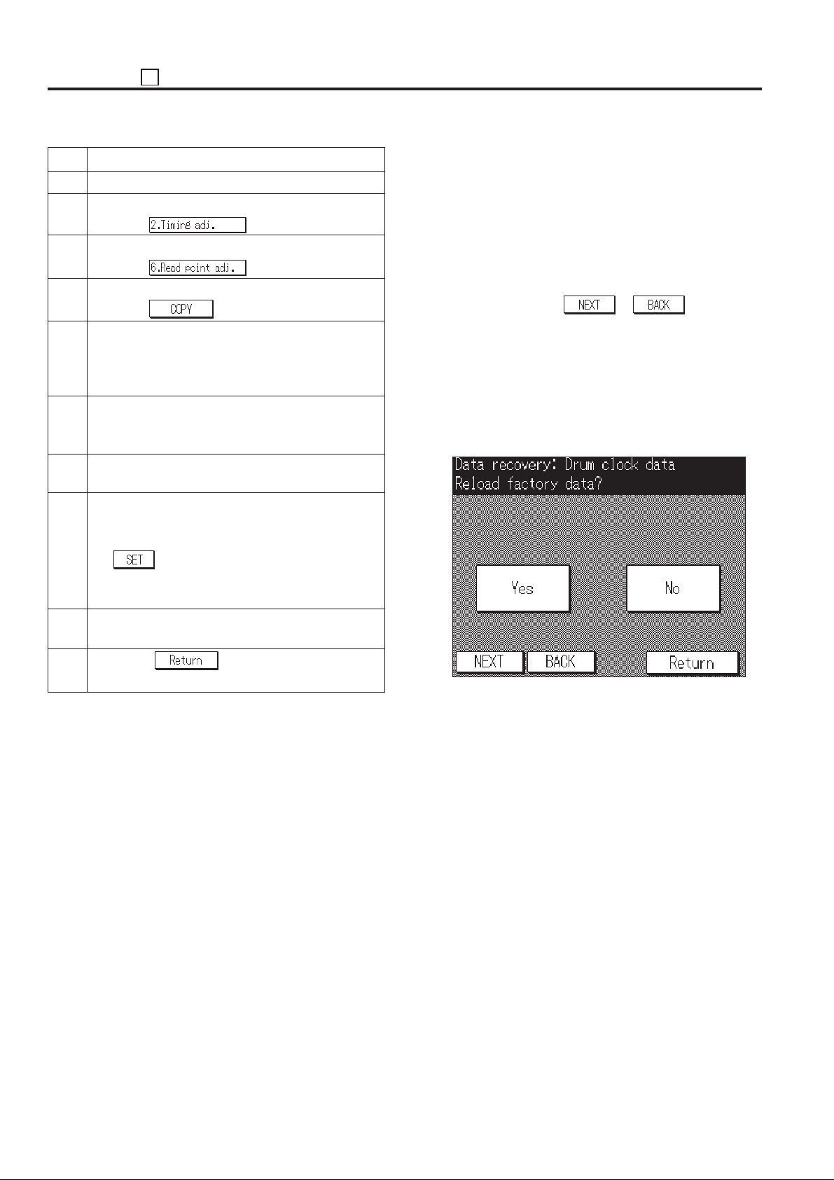
ADJUSTMENT 36
Step Operation procedure
1 Enter the 36 mode.
2 [36 mode menu screen]
Press the key.
3 [Timing adjustment menu screen]
Press the
4 [Image read point adjustment screen]
Press the key.
5 [Basic screen]
Set the new pyramid chart on the original glass and
select A3 or 11 x 17 size paper, then press the Start
print button to make a test copy.
6 Preform a comparison between original image and
test copy image. Then check the image read point.
Standard value: Within ± 3.0 mm
7 Press the C button while pressing the P button to
return to the image read position adjustment screen.
8 [Image read point adjustment screen]
If the image read point is different to the standard
value, enter a value from the numeric key, then press
the
Input range = –31 (small) ~ + 31 (large)
9 Repeat steps 4 to 8 until the image read point is within
standard value.
10 Press the key to return to the timing
adjustment menu screen.
key to store the adjustment value.
1 step = 0.13 mm
key.
7. Resetting Standard Data
Reset the adjusted set values of timing adjustment to the
standard values (factory set data).
Select the [2. Timing adj.] in the 36 mode menu screen, then the
timing adjustment menu screen will appear.
Select the [7. Factory default] on this screen, then the resetting
standard data screen will appear.
This adjustment can be reset the following item adjusted set
values to the standard values (factory set data). These can be
selected by pressing the
a. Vertical/Horizontal magnification adjustment
b. Restart timing adjustment
c. Paper feed loop amount adjustment
d. Leading edge original erasure adjustment
e. Centering adjustment
f. Image read point adjustment
[Resetting standard data screen (Example: Vertical
magnification adjustment)]
or key.
5 - 66
Page 68
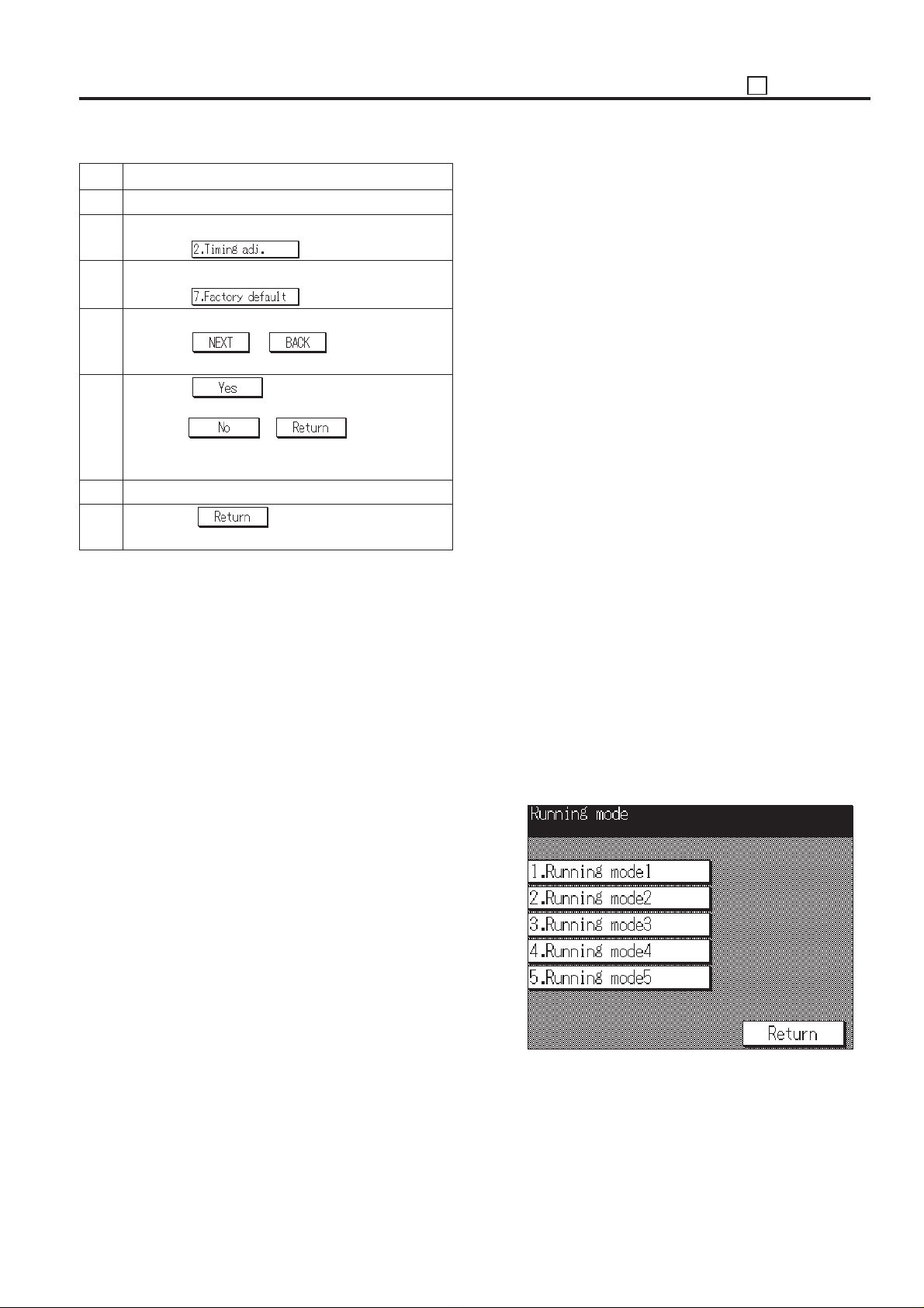
36 ADJUSTMENT
Step Operation procedure
1 Enter the 36 mode.
2 [36 mode menu screen]
Press the key.
3 [Timing adjustment menu screen]
Press the
4 [Resetting standard data screen]
Press the or key until the desire
item will appear in the message display area.
5 Press the key to reset the set values to
the standard values that has been selected item.
Press the
values are not reset and return to the timing adjust-
ment menu screen.
6 To reset another adjustment item, repeat steps 4 to 5.
7 Press the key to return to the timing
adjustment menu screen.
key.
or key, then the set
[4] Running Test Mode
Select the [3. Running mode] in the 36 mode menu screen,
then the running test mode menu screen will appear.
The following items can be selected.
1. Running mode 1 (Intermittent copy mode)
Running mode 1 is an intermittent copy mode. In this
mode, after the set number of copy operations has been
completed, the machine goes into the copy ready status,
waits 0.5 sec, then starts the same operation again.
2. Running mode 2 (Paperless intermittent copy mode)
Running mode 2 is a paperless intermittent copy mode. It
makes copies at roughly the same timing as for a normal
copy, without performing paper detection or jam detection. Also, like running mode 1, after the set number of
copy operations has been completed, the machine goes
into the copy ready status, waits 0.5 sec, then starts the
same operation again.
3. Running mode 3 (paperless mode)
Running mode 3 is a paperless mode. It makes copies at
roughly the same timing as for a normal copy, without
performing paper detection or jam detection.
4. Running mode 4 (Paper less endless mode)
Running mode 4 is a paperless endless mode. It automatically sets the copy quantity to infinity. Also, like
running mode 3, it makes copies at roughly the same
timing as for a normal copy, without performing paper
detection or jam detection.
5. Running mode 5
Running mode 5 is a process running mode. It consists
of running mode 4 plus an operation consisting of an
optics each-time scan and an automatic paper feed tray
change.
[Running test mode menu screen]
5 - 67
Page 69
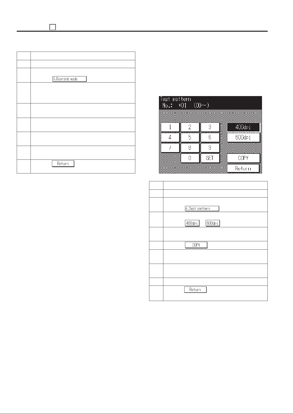
ADJUSTMENT 36
Step Operation procedure
1 Enter the 36 mode.
2 [36 mode menu screen]
Press the key.
3 [Running test mode menu screen]
Press the key according to the desired running mode.
(Mode 1 to Mode 5)
4 [Basic screen]
Press the start print button.
5 After checking the copy operation, press the Stop/
Clear button to stop copy operation.
6 Press the C button while pressing the P button to
return to the running test mode menu screen.
7 To perform another running test mode, repeat steps
3 to 6.
8 Press the key to return to 36 mode menu
screen.
[5] Test Pattern Output
To output a test pattern.
Select the [4. Test pattern] in the 36 mode menu screen, then
the test pattern output screen will appear.
Caution: Do not operate pattern numbers that are not particu-
larly specified.
[Test pattern output screen]
Step Operation procedure
1 Enter the 36 mode.
2 [36 mode menu screen]
Press the
3 [Test pattern output screen]
Press the or key.
4 Enter a pattern number according to the desired test
pattern.
5 Press the key.
key.
5 - 68
6 [Basic screen]
Press the Start print button to output a test pattern.
7 Press the C button while pressing the P button to
return to the test pattern output screen.
8 To output a different test pattern, repeat steps 3 to 7.
9 Press the key to return to 36 mode menu
screen.
Page 70
No.1 Overall halftone
[Check item]
• When the density is set to 70 (halftone)
If white stripes, black stripes, or uneven density can be seen, determine that the printer system is abnormal.
• When the density is set to 0 (white)
If the test pattern is fogged, determine that the printer system (writing section, process section) is abnormal.
• When the density is set to 255 (black)
If the density is light, determine the printer system density is too low.
* For details of setting the density, refer to [6] Test pattern density adjustment on page 5-75.
36 ADJUSTMENT
Test Pattern
MODEL
7040
SERVICE HANDBOOK
REVISED EDITIONMANUAL
5 - 69
DATE
MAR. 1998
PAGE
5-69
METHOD
REPLACEMENT
Page 71
ADJUSTMENT 36
No.2
No.49
[Check item]
No.2 test pattern is output with gamma corrected.
No.49 test pattern is output without gamma corrected.
Check that the gamma correction operates properly by the outputting these two test patterns.
Check that No.2 test pattern is output with the smooth halftone until from the upper left patch to the lower right
patch. Perform the “d. Gamma curve preparation” of the “1. Patch method PWM gamma correction” in the “[7]
Image Quality Adjustment” when an abrupt tone jump occurs or the patch output starting point is slow. If the
overall halftone does not become normal, perform the “a” to “d” of the “1. Patch method PWM gamma
correction” in the “[7] Image Quality Adjustment”. I cace it is still not improved, clean or replace the related parts.
Grayscale pattern
Test Pattern
MODEL
7040
SERVICE HANDBOOK
REVISED EDITIONMANUAL
5 - 70
DA TE
MAR. 1998
Ignore this part since it is a
repeated pattern.
PAGE
5-70
METHOD
REPLACEMENT
Page 72
No.11 Writing system check
[Check item]
Check the writing system abnormality (condition of resolution, reproducibility of independence point and so on)
36 ADJUSTMENT
Test Pattern
5 - 71
Page 73
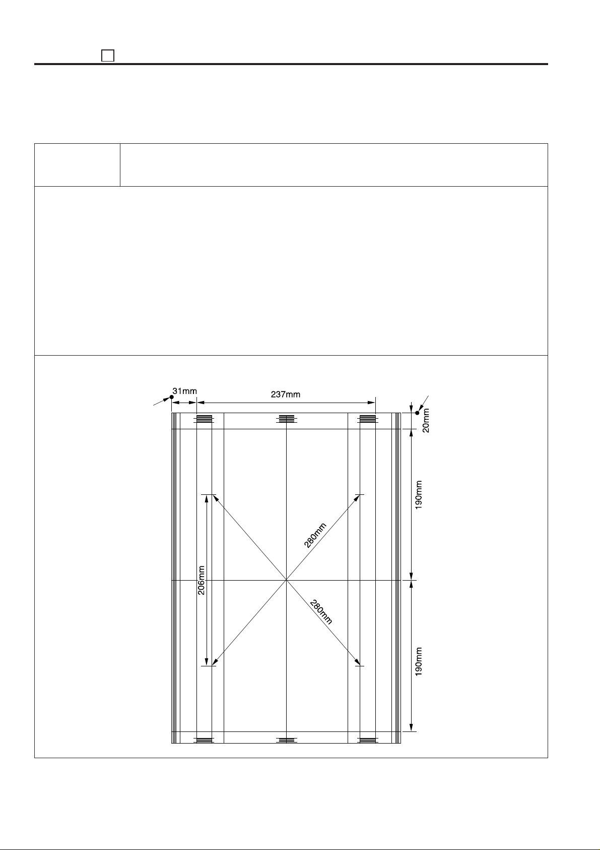
ADJUSTMENT 36
No.16 Linearity evaluation pattern
[Check item]
Judge from this test pattern which of the scanner system and the printer system is abnormal. Items that can
be checked include horizontal magnification, vertical magnification, tilt image, and leading edge timing of the
printer system. If the copy image is defective despite no abnormality being visible on the test pattern, the
scanner system is defective.
Test Pattern
Paper edge
Paper edge
5 - 72
Page 74
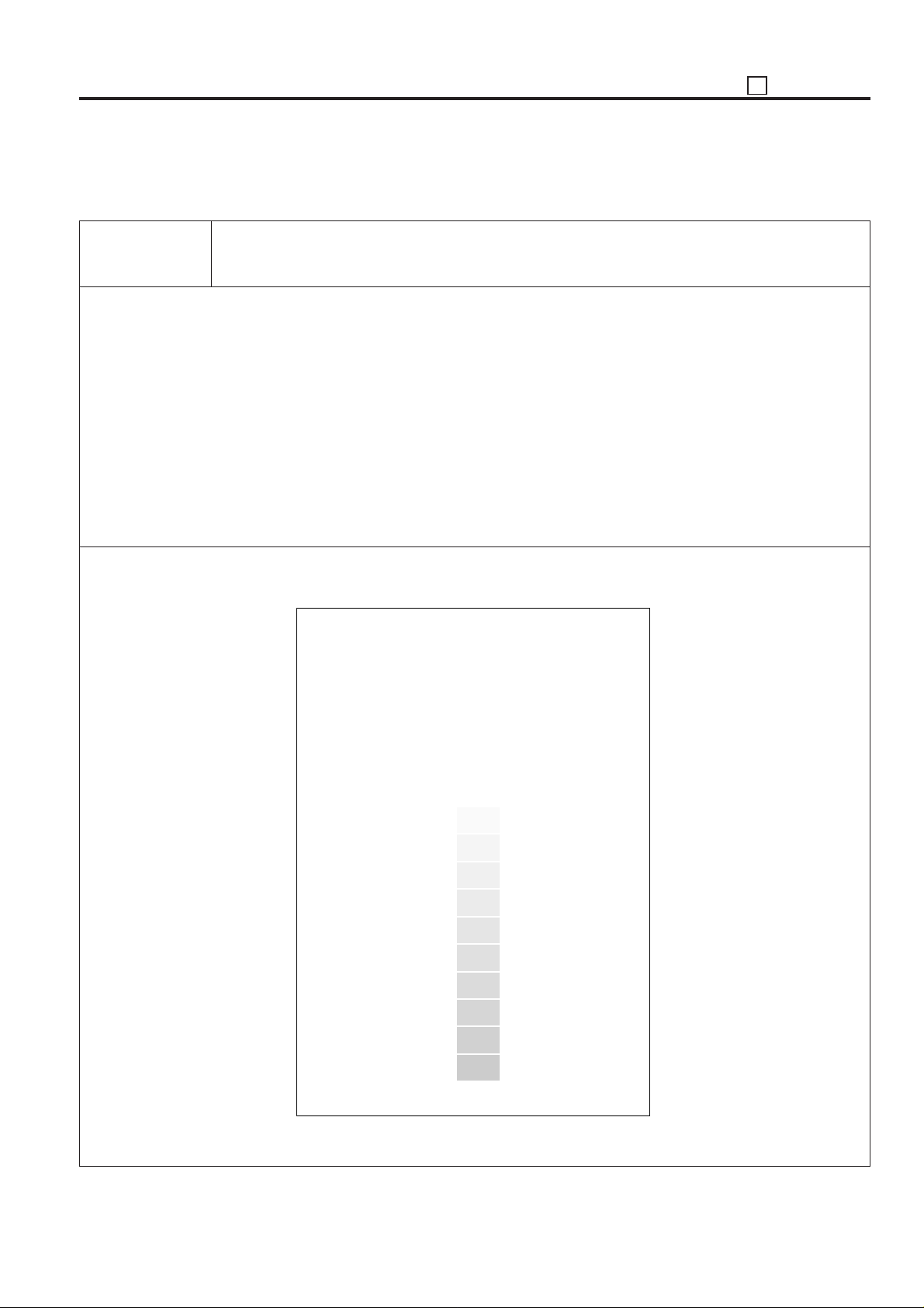
No.50 Patch pattern
[Check item]
This test pattern is used when the patch method PWM gamma correction adjustment is performed with No. 51
pattern.
Refer to the “b. SGU pattern print” of the “1. Patch method PWM gamma correction” in the “[7] Image Quality
Adjustment”.
36 ADJUSTMENT
Test Pattern
5 - 73
Page 75
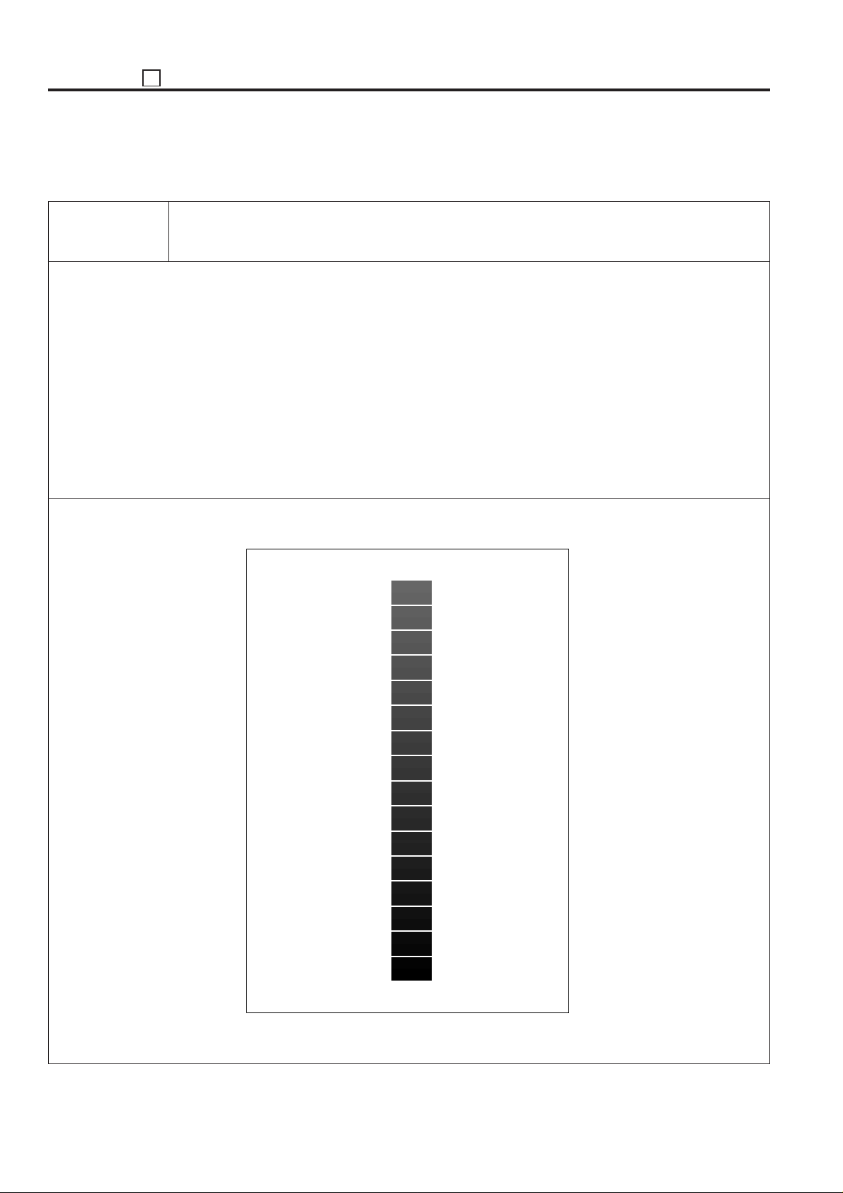
ADJUSTMENT 36
No.51 Patch pattern
[Check item]
This test pattern is used when the patch method PWM gamma correction adjustment is performed with No. 50
pattern.
Refer to the “b. SGU pattern print” of the “1. Patch method PWM gamma correction” in the “[7] Image Quality
Adjustment”.
Test Pattern
5 - 74
Page 76
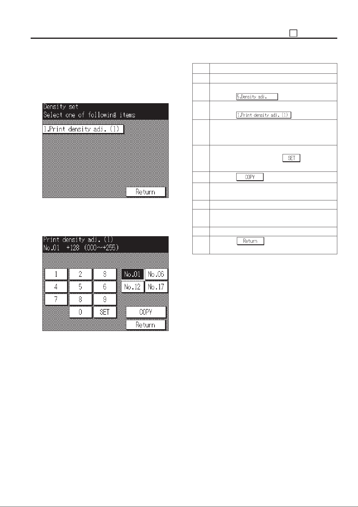
36 ADJUSTMENT
[6]Test Pattern Density Adjustment
Adjustment of the density of the test pattern.
Select the [5. Density set] in the 36 mode menu screen, then
the print density adjustment menu screen will appear.
[Print density adjustment menu screen]
Select the [1. Print density adj. (1)] in the print density adjustment menu screen, then the print density adjustment screen
will appear.
[Print density adjustment screen]
Step Operation procedure
1 Enter the 36 mode.
2 [36 mode menu screen]
Press the key.
3 [Print density adjustment menu screen]
Press the
4 [Print density adjustment screen]
Press the key according to the desire test pattern to
be adjusted. (No.01, No.06, No.12 and No.17)
5 Enter the desired density by a numeric value from the
numeric keys, then press the key.
Input range: 000 (light) to +255 (dark)
6 Press the key.
7 [Basic screen]
Press the Start print button to output a test pattern.
8 Check the density of the output test pattern.
9 Press the C button while pressing the P button to
return to the print density adjustment screen.
10 To adjust another test pattern, repeat steps 4 to 9.
11 Press the
adjustment menu screen.
key to return to Print density
key.
5 - 75
Page 77
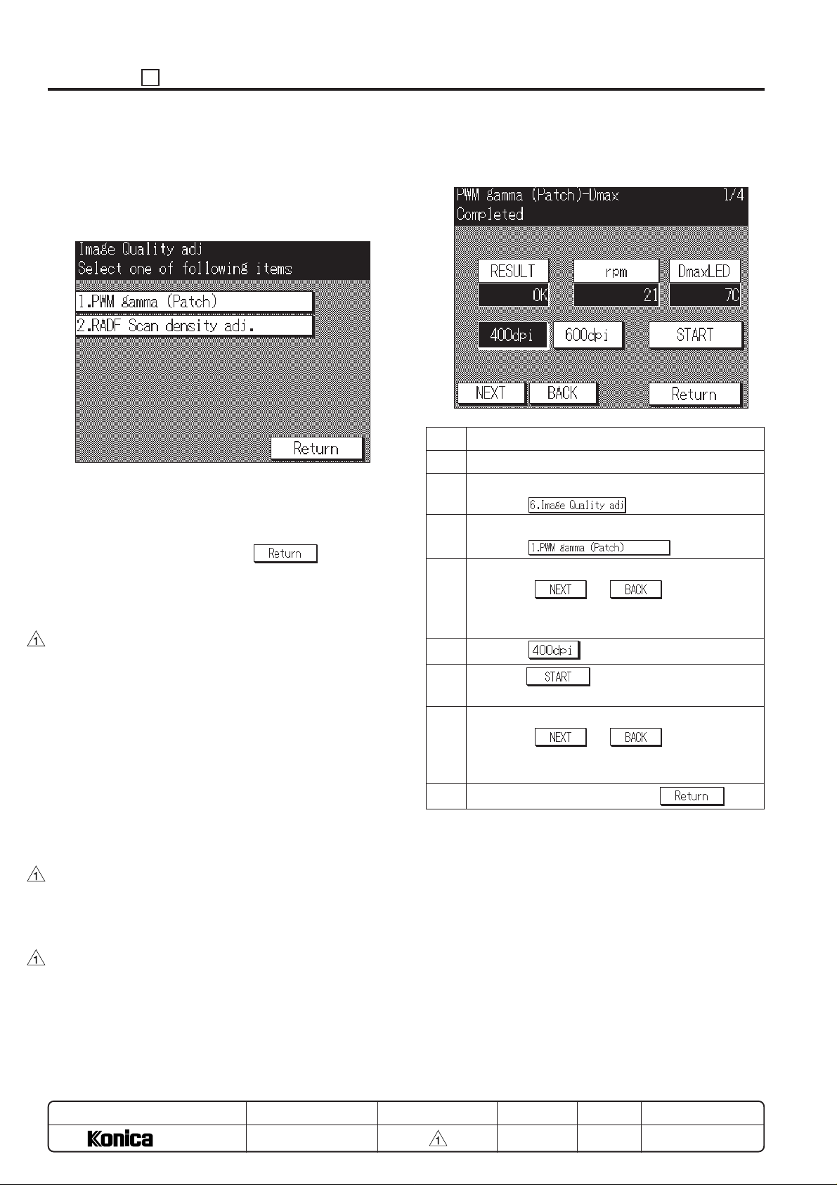
ADJUSTMENT 36
[7] Image Quality Adjustment
This function adjusts the two kinds of image quality adjustment.
(1) Select the [6. Image Quality adj.] in the 36 mode menu
screen, then the image quality adjustment screen will
appear.
[Image quality adjustment menu screen]
(2) Press the key according to the item to be adjusted.
The selected adjustment screen will appear.
(3) Enter data on each screen.
(4) To end the adjustment, press the
to the Image quality adjustment menu screen.
1. Patch method PWM gamma correction
Preform PWM gamma correction (Dmax sensor correction) by
reading SGU test pattern. (*1,2)
Perform the following four adjustment items in the order A, B,
C and D.
a. Dmax correction
Setting the darkest density.
b. SGU pattern print
Output a SGU pattern (No.50, No.51) to use with the
gamma correction.
c. Gamma correction
Read the output pattern by the scanner of the copier with
the “b. SGU pattern print” and calculate the correction
value from the PWM value when pattern has been output
and read pattern density.
d. Gamma curve preparation
Based on the correction value obtained in the gamma
correction and the patch read level, calculate the correc-
tion value of the Dmax sensor and create the gamma
curve.
*1: If this correction is not completed correctly, it is possible
that the halftone reproduction of the S-fine and fine is
decreased.
*2: When performing this operation, close the side plate at
the side of the main body and the rear cover.
key to return
a. Dmax correction
[Dmax correction screen]
Step Operation procedure
1 Enter the 36 mode.
2 [36 mode menu screen]
Press the
3 [Image quality adjustment menu screen]
Press the key.
4 [Dmax correction screen]
Press the
gamma (Patch)-Dmax” will appear in the message
display area.
5 Press the
6 Press the key, then confirm that the “OK”
is displayed in [RESULT] indication area. *3
7 Preform “b. SGU pattern print” next.
Press the or key until “PWM
gamma (Patch)-SGU” will appear in the message
display area.
8 To end the adjustment, press the key.
*3: Preform next adjustment, after displaying the “OK” in
[RESULT] display area.
key.
key.
or key until “PWM
MODEL
7040
SERVICE HANDBOOK
REVISED EDITIONMANUAL
5 - 76
DA TE
MAR. 1998
PAGE
5-76
METHOD
REPLACEMENT
Page 78
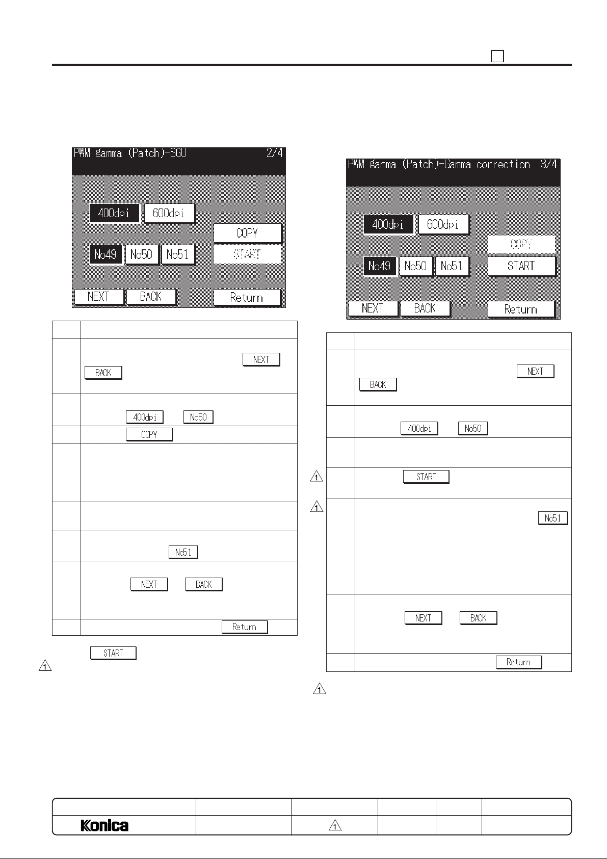
36 ADJUSTMENT
b. SGU pattern print
Output test patterns No.50 and No.51.
[SGU pattern print screen]
Step Operation procedure
1 After [a. Dmax correction] (last adjustment item) is
completed correctly, then press the or
key until “PWM gamma (Patch)-SGU” will
appear in the message display area.
2 [SGU test pattern print screen]
Press the and key.
3 Press the
4 [Basic Screen]
Select A3 or 11x17 size paper, then press the Start
print button. (*2)
Test pattern No.50 is outputted.
5 Press the C button while pressing the P button to
return to the SGU test pattern print screen.
6 Repeat steps 2 to 4 to output the Test pattern No.51.
(In step 2, press the
7 Preform “c. gamma correction” next.
Press the
gamma (Patch)-Gamma correction” will appear in the
message display area.
8 To end the adjustment, press the key.
*1: The key can not be pressed on this screen.
*2: Use the fine paper as a copy paper. If using the recycled
paper such as yellow or colored paper, the correction may
not be performed correctly.
key. (*1)
key)
or key until “PWM
c. Gamma correction
Read the two test patterns that outputted in “b. SGU pattern
print” by scanner.
[Gamma correction screen]
Step Operation procedure
1 After [b. SGU pattern print] (last adjustment item) is
completed correctly, then press the or
key until “PWM gamma (Patch)-Gamma
correction” will appear in the message display area.
2 [SGU test pattern print screen]
Press the and key.
3 Set the test pattern No.50 that outputted in SGU
pattern print on the original glass. (*3,*4)
4 Press the key to read the test pattern
No.50 with the scanner. (*5)
5 Replace the original with No.51 that outputted in SGU
pattern print and repeat step 3 and 4. (Press
key at step 2.) (*3)
When step 4 of No.51 is finished, the correction data
is started to calculate, the normal completion or error
is displayed. When an error has occurred, perform
from a again.
6 Preform “d. gamma curve preparation” next.
Press the or key until “PWM
gamma (Patch)-Gamma curve” will appear in the
message display area.
7 To end the adjustment, press the key.
*3: Read No.51 (darker) after No.50 (lighter) reading. Be
careful of the reading order.
MODEL
7040
SERVICE HANDBOOK
REVISED EDITIONMANUAL
5 - 77
DATE
MAR. 1998
PAGE
5-77
METHOD
REPLACEMENT
Page 79
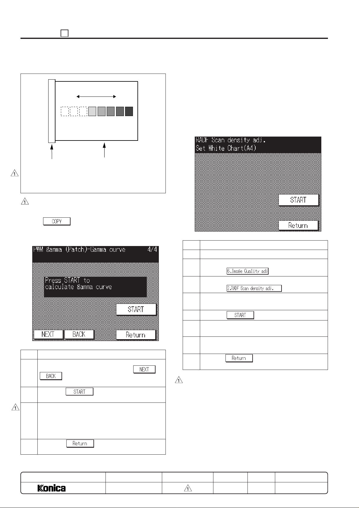
ADJUSTMENT 36
*4: Set direction of SGU pattern
DarkLight
Original stopper plate
View from the rear of the original.
Place the original so that its print side points downward
as usual.
· Be sure to place the SGU test pattern with the light
density side against the original stopper plate on the
platen. Be sure to close the platen cover.
*5: The
d. Gamma curve preparation
[Gamma curve preparation screen]
Step Operation procedure
1 After [c. gamma correction] (last adjustment item) is
completed correctly, then press the or
curve” will appear in the message display area.
2 Press the
Scanner reads the test pattern No.50.
3 When the gamma curve is prepared, “Completed” will
appear in the message display area.
Perform “a” to “d” again when an error is displayed. When
the normal completion can not be made even if it is
repeated several times, clean or replace the related parts.
4 Press the
quality adjustment menu screen.
key can not be pressed on this screen.
key until “PWM gamma (Patch)-Gamma
SGU pattern
key.
key to return to the image
2. RADF scanning density adjustment
When the original glass (1) is replaced, adjusts the density
when reading the original with the RADF.
Before preforming this adjustment, be careful of the following
items.
(1) The mechanical adjustment, optical adjustment and elec-
trically adjustment of the scanner were completed.
(2) Clean the original glass (1).
(3) The white chart is not dirty or folded.
[RADF scanning density adjustment screen]
Step Operation procedure
1 Enter the 36 mode.
2 [36 mode menu screen]
Press the
3 [Print density adjustment menu screen]
Press the
4 [RADF scanning density adjustment screen]
Set the white chart on the RADF. (*1)
5 Press the
6 Check that the “Completed” will appear in the mes-
sage display area.
7 If the “Error” will appear in the message display area,
then repeat steps 4 and 5.
8 Press the
adjustment menu screen.
*1: Be sure to set the white chart orientation to the orientation
of A4. It will not be adjusted correctly in the orientation of
A4R. Place the white chart so that the finer side is the front
side.
*2: If “ERROR” is displayed repeatedly, there is a possibility
in the adjustment of the scanner machine, optics, electricrelated or parts defect.
key.
key.
key.
key to return to the print density
MODEL
7040
SERVICE HANDBOOK
REVISED EDITIONMANUAL
5 - 78
DA TE
MAR. 1998
PAGE
5-78
METHOD
REPLACEMENT
Page 80
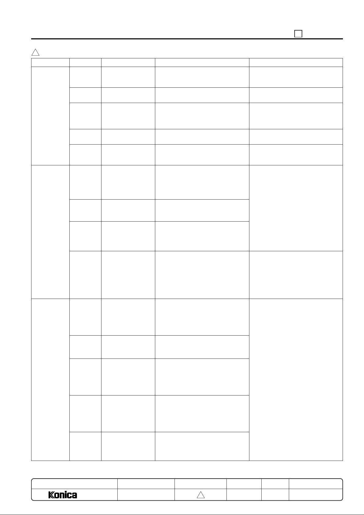
36 ADJUSTMENT
3
Error Code Table for PWM Gamma Correction (patch method)
Classification
Dmax
Correction
Gamma
Correction
Gamma
Curve
Preparation
*1: The error code for Gamma correction and Gamma Curve preparation is displayed in a 4 digit hex value and when multiple errors
occur, the results of the sum is displayed. (For example, when error codes 0400 and 0800 happen at the same time, 0C00.)
Error Code
0001
0002
0003
0004
0005
0008
0400
0800
1000
0008
0080
0100
0200
0800
Cause
Drum reflective light
insufficient
Developer performance insufficient
Patch detection defective
Drum reflective light
excessive
Dmax sensor output
abnormality
Data precision defective
Insufficient data numbers read
Insufficient gradation
numbers read
Dmax sensor detection value error
Data precision defective
Dmax sensor detection value error
Dmax sensor detection value error
Dmax sensor proofing error
Gamma curve error
Amount of reflective light from drum
does not meet standard even after modi-
fying Dmax sensor LED light amount.
Patch density does not meet standard
even when developer rotation is maximum
Patch on drum cannot be detected
Amount of reflective light from drum
detected by Dmax sensor is too much.
Dmax sensor output can hardly be
detected
Too many discrepancies in data for proofing by calculation the relationship of the
value read by the Dmax sensor patch
and the scanner patch density, and the
precision of the calculation is defective.
Patch data numbers read by scanner
is less than what is required in the
above calculation.
Patch level numbers read by scanner
is less than what is required in the
above calculation.
The density of the patch read by the
Dmax sensor is almost the same for the
lowest and highest density and so the
above calculation could not be done.
The data for calculating the PWM
correction curve from the value read
by Dmax sensor patch has too many
discrepancies and the precision of
the calculation is defective.
The Dmax sensor value was below the
standard and so the PWM correction
curve could not be calculated.
The density of the patch read by the
Dmax sensor is almost the same for
the lowest and highest density and so
the PWM correction curve could not
be calculated.
There was no difference between the
lowest and highest density in the Dmax
sensor ouput converted with the proofing value and so the PWM correction
curve could not be calculated.
The PWM correction curve prepared by
calculation has a special attribute that
does not allow it to be increased monotonously and so could not be used.
Condition
Probable location of Abnormally
· Dmax sensor cleaning
· TCSB (Toner controller sensor board)
· PRDB (Printer drive board)
·
Check for problems in patch prepara-
tion (between charging ~ developing).
·
Check to see whether drum coupling
shaft is properly set.
·
Check for problems in patch preparation
(between exposure ~ developing)
· TCSB (Toner control sensor board)
· PRDB (Printer drive board)
· Check drum unit drawer connection.
· TCSB (Toner control sensor board)
· PRDB (Printer drive board)
· In a series of operations, errors may
occur even when performing proper
operations due to discrepancies in
the values read by the machine,
return to [a. Dmax correction] and
repeat 2 ~ 3 times.
· Check whether there were any problems with operation procedures,
SGU pattern original setting direction, size, image or the like.
· Check for abnormalities in SGU output, patch preparation (between
charging ~ developer), TCSB (toner
controller sensor board), reader related items.
· Check to see if the drum coupling
shaft is properly set.
· Check the drawer connection of the
drum unit.
· Check for problems in the TCSB
(Toner control sensor board), patch
preparation (between the exposure
~ developing).
· In a series of operations, errors may
occur even when performing proper
operations due to discrepancies in
the values read by the machine,
return to [a. Dmax correction] and
repeat 2 ~ 3 times.
· Check for abnormalities in SGU output, patch preparation (between
charging ~ developer), TCSB (toner
controller sensor board), reader related items.
MODEL
7040
MANUAL
SERVICE HANDBOOK
REVISED EDITION
5 - 79
3
DATE
Mar. 1999
PAGE
5-78-1
METHOD
ADDITION
Page 81
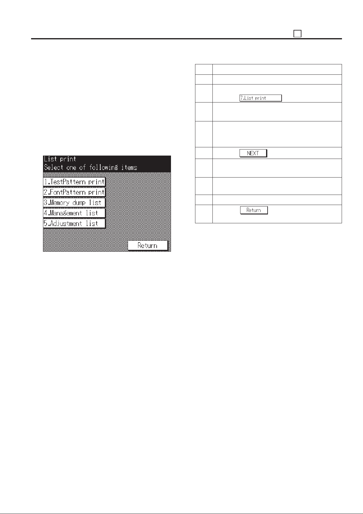
36 ADJUSTMENT
[8] List Print (Service data Print)
Select the [7. List print] in the 36 mode menu screen, then the
list print menu screen will appear.
The following items can be selected on this screen.
a. Test pattern
b. Font pattern
c. Memory dump list
d. Management list
e. Adjustment list
Caution: Do not operate for any list that is not particularly
specified.
[List print menu screen]
Step Operation procedure
1 Enter the 36 mode.
2 [36 mode menu screen]
Press the key.
3 [List print menu screen]
Select the desired list to be outputted.
4 [List print screen]
Only when outputting the memory dump list, set the
start address and end address. (*1)
5 Press the
6 [Basic screen]
Press the Start print button to output the list.
7 Press the C button while pressing the P button to
return to the list print screen.
8 To output a different list, repeat steps 3 to 7.
9 Press the key to return to the 36 mode
menu screen.
*1: The memory damp list is dam-output with both type of the
Hex/ASCII.
key.
5 - 79
Page 82
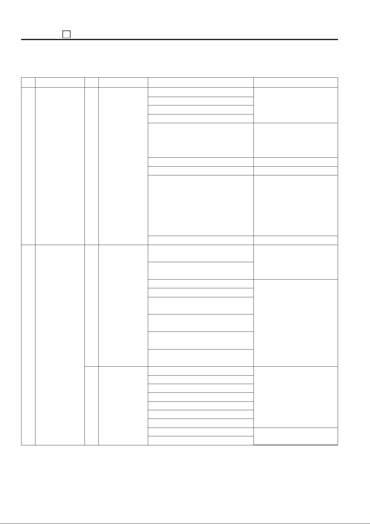
ADJUSTMENT 36
36 mode adjustment items list
No. Menu No. Sub menu Circulating menu Operation outline
High voltage ad-
1
justment
2
Timing adjustment 1
None
Vertical/Horizontal
magnification adjustment
2
Restart timing adjustment
Charging Corona Voltage Adjustment
Transfer Current Adjustment
Separation (AC) Voltage Adjustment
Separation (DC) Current Adjustment
Charging Grid Voltage Adjustment
Developing Bias Adjustment
Dmax Correction
L detection Adjustment
Toner automatic supply
Printer vertical magnification adjustment
(400dpi)
Printer vertical magnification adjustment
(600dpi)
Platen vertical magnification adjustment
Platen horizontal magnification adjustment
RADF (50%) vertical magnification adjustment
RADF (100%) vertical magnification adjustment
RADF (200%) vertical magnification adjustment
RADF (400%) vertical magnification adjustment
Engine restart timing adjustment (All)
Engine restart timing adjustment (Tray )
Engine restart timing adjustment (DB1)
Engine restart timing adjustment (DB2)
Engine restart timing adjustment (DB3)
Engine restart timing adjustment (By-pass)
Engine restart timing adjustment (ADU)
RADF timing adjustment (front side)
RADF timing adjustment (back side)
Adjustment is inhibited in the field.
After entering a data, press the
Start print button to start the operation. Press the Stop/Clear
button to stop the operation.
Adjustment is inhibited in the field.
Adjustment is inhibited in the field.
Perform the L detection adjustment of the toner supply and register the result in the non-volatile
memory. Displays the result and
L detection adjustment value at
the end. The developing counter
is reset.
Adjustment is inhibited in the field.
After adjustment, output the SGU
pattern. (No.16)
After adjustment, make a test
copy.
After adjustment, output the SGU
pattern. (No.16)
After adjustment, make a test
copy.
5 - 80
Page 83
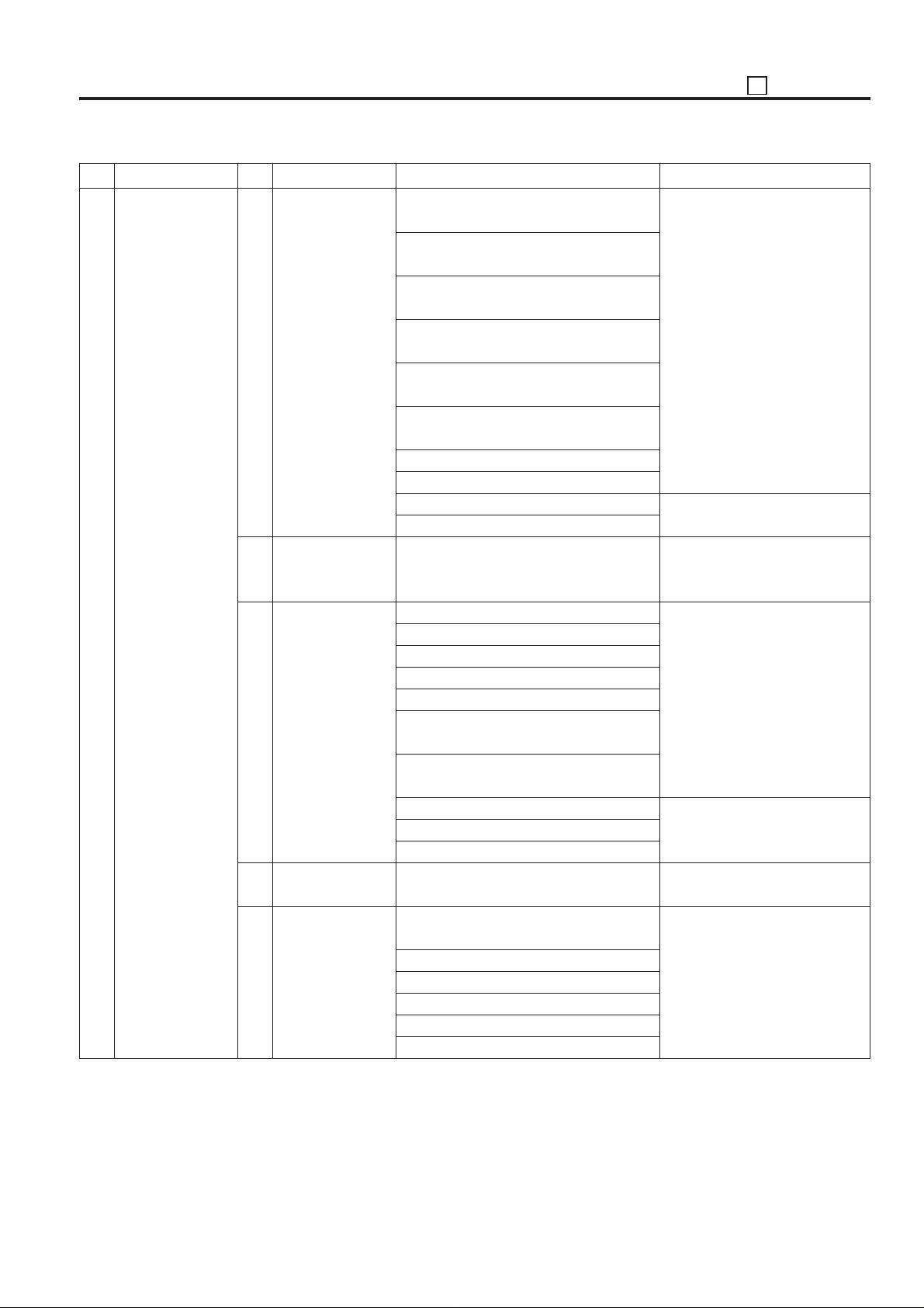
36 ADJUSTMENT
No. Menu No. Sub menu Circulating menu Operation outline
Timing adjustment 3
2
Paper feed loop
amount adjustment
4
Leading edge
original erasure
adjustment
5
Centering
adjustment
6
Image read point
adjustment
7
Resetting standard data
Paper feed loop amount adjustment (ADU,
small size)
Paper feed loop amount adjustment (ADU,
large size)
Paper feed loop amount adjustment (Tray,
small size)
Paper feed loop amount adjustment (Tray,
large size)
Paper feed loop amount adjustment (Bypass, plain paper)
Paper feed loop amount adjustment (Bypass, thick paper)
Paper feed loop amount adjustment (DB)
ADU loop amount adjustment
RADF loop amount adjustment (front side)
RADF loop amount adjustment (back side)
None
Image writing centering adjustment (All)
Image writing centering adjustment (Tray)
Image writing centering adjustment (DB1)
Image writing centering adjustment (DB2)
Image writing centering adjustment (DB3)
Image writing centering adjustment (Bypass)
Image writing centering adjustment
(ADU)(Co/L/M/S/SS)
Platen centering adjustment
RADF centering adjustment (front side)
RADF centering adjustment (back side)
Point of origin adjustment
Vertical/Horizontal magnification adjustment
Restart timing adjustment
Paper feed loop amount adjustment
Leading edge original erasure adjustment
Centering adjustment
Image read point adjustment
After adjustment, output the SGU
pattern. (No.16)
After adjustment, make a test
copy.
After adjustment, make a test
copy.
After adjustment, output the SGU
pattern. (No.16)
After adjustment, make a test
copy.
Return the adjustment data to the
factory setting.
5 - 81
Page 84
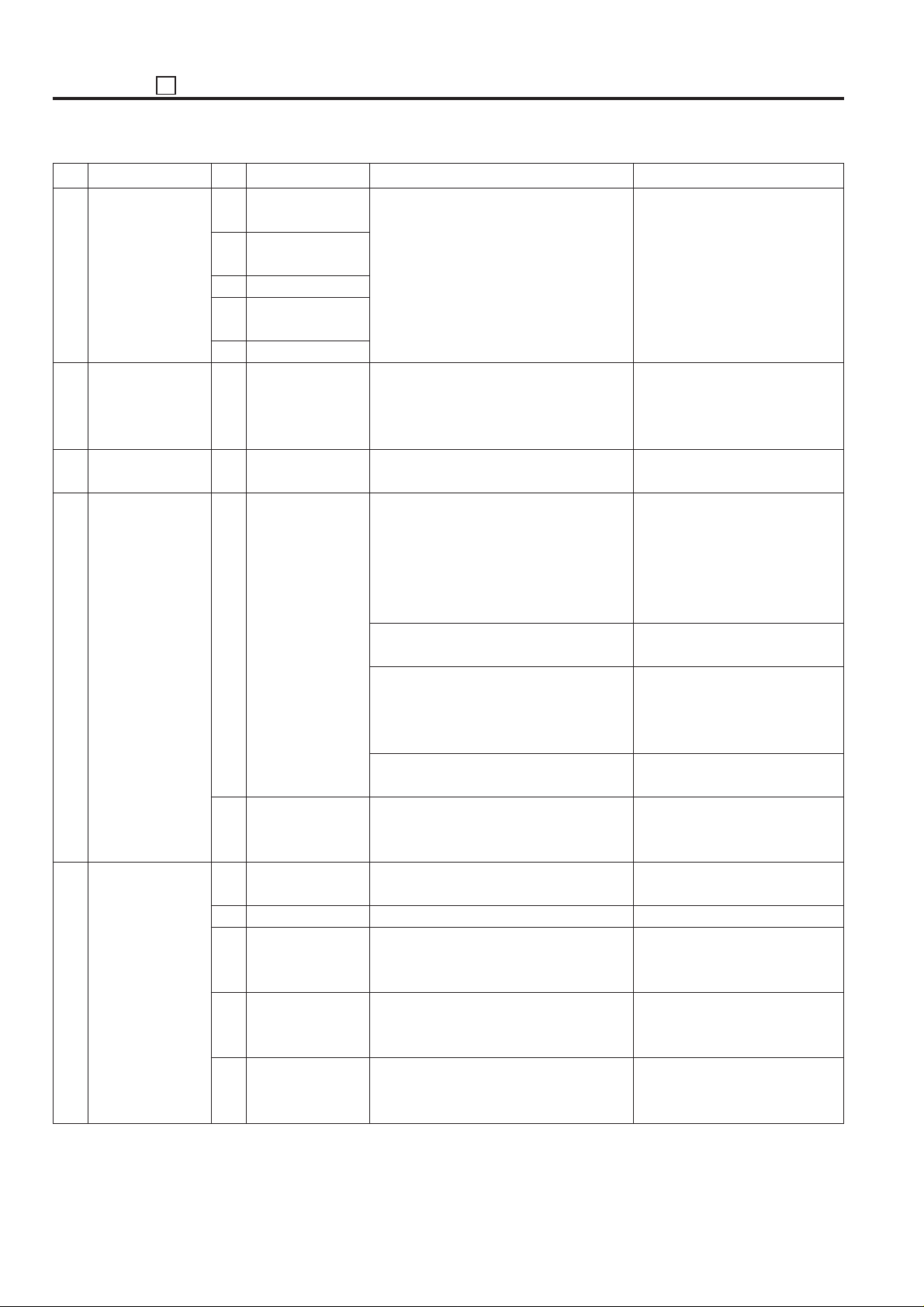
ADJUSTMENT 36
No. Menu No. Sub menu Circulating menu Operation outline
Running test
3
mode
4
Teat pattern
output
5
Density adjustment
6
Image quality
adjustment
7
List print
1
Intermittent copy
mode
2
Paperless intermittent copy mode
3
Paperless mode
4
Paper less endless mode
5
Running mode
None
1
Test pattern density adjustment
1
PWM gamma
correction(Patch
method)
2
RADF scanning
density adjustment
1
Test pattern
2
Font pattern
3
Memory dump
list
4
Management list
5
Adjustment list
None
None
None
Dmax correction
SGU pattern print
Gamma correction
Gamma curve preparation
None
None
None
None
None
None
After selection, operation starts.
Output the SGU pattern according to the specified number. The
resolution can be switched with
400/600dpi.
After adjustment, output the
specified SGU pattern.
Perform the Dmax correction and
register the result in the non-volatile memory.
Displays the result and
DmaxLED/sleeve rotation value
at Dmax correction completion.
Output the specified SGU pattern
from the basic screen.
Read the output SGU pattern
using the scanner, then calculate
the PWM gamma correction value
and display the result.
Create the gamma curve with the
start Print button ON.
Read the white chart to adjust the
density.
Grid pattern of the 2-dot in line
width and 500 dot in line interval.
Print out the stored font pattern.
Damp print out the stored data
from the specified address with
both type of the Hex and ASCII.
Output the machine condition,
counter data and jam history and
so on.
Output only the 25/36 mode adjustment value in the management list.
5 - 82
Page 85
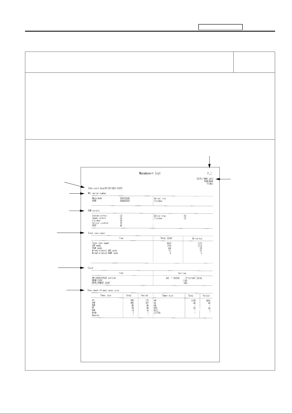
MANAGEMENT LIST ADJUSTMENT
Management list P. 1
[Description items]
• Serial number setting
• ROM version display (ROM version for the control board)
• Copy count (Data collection 1)
Total count and periodic date count of each mode.
• Counter check
• Copy count of each paper size (Data collection 2)
Total count and periodic date count of each paper size
Management list
Number of page
Periodic date data
collection start date
Serial number setting
ROM version display
Copy count
Counter check
Copy count of each
paper size
Output date, main
body serial number,
and total copy count
5 - 83
Page 86
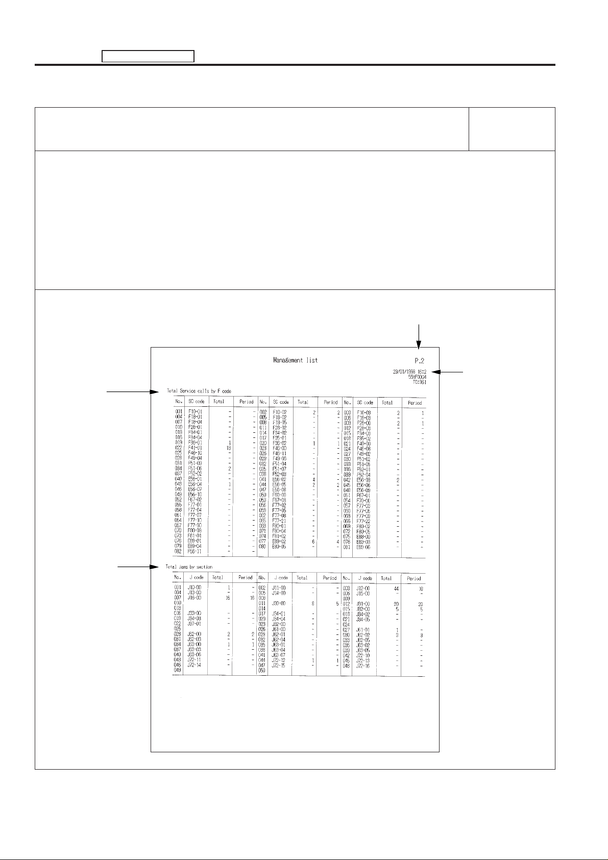
ADJUSTMENT MANAGEMENT LIST
Management list P. 2
[Description items]
• F(S/C) code count (Data collection 4)
Total count and periodic date count of each code.
• JAM code count (Data collection 2)
Total count and periodic date count of each code.
Management list
Number of page
F code count
JAM code count
Output date, main
body serial number,
and total copy count
5 - 84
Page 87
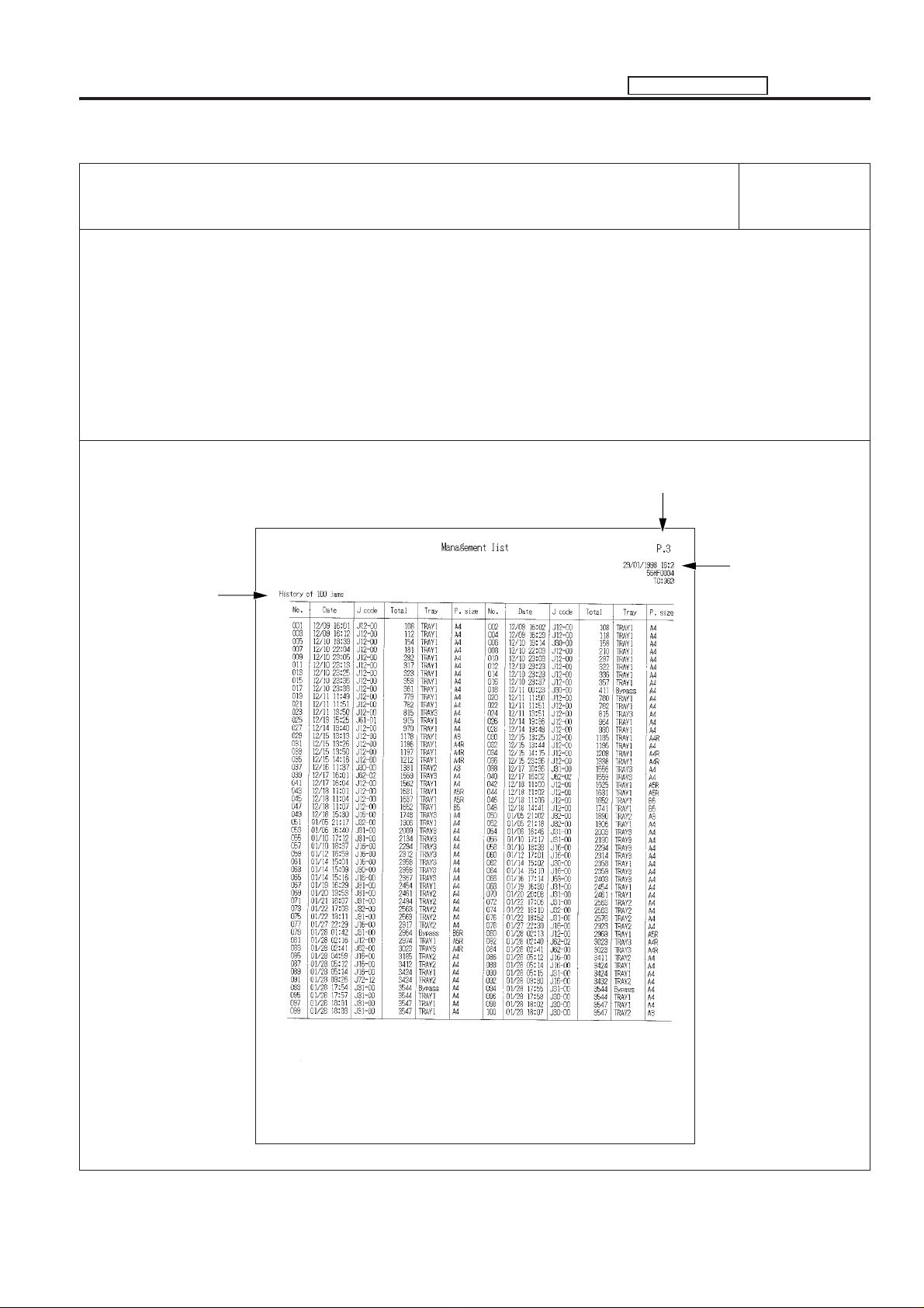
MANAGEMENT LIST ADJUSTMENT
Management list P. 3
[Description items]
• The last JAM history
The last 100 JAM data, code, total copy count, tray and paper size
Management list
Number of page
The last JAM history
Output date, main
body serial number,
and total copy count
5 - 85
Page 88
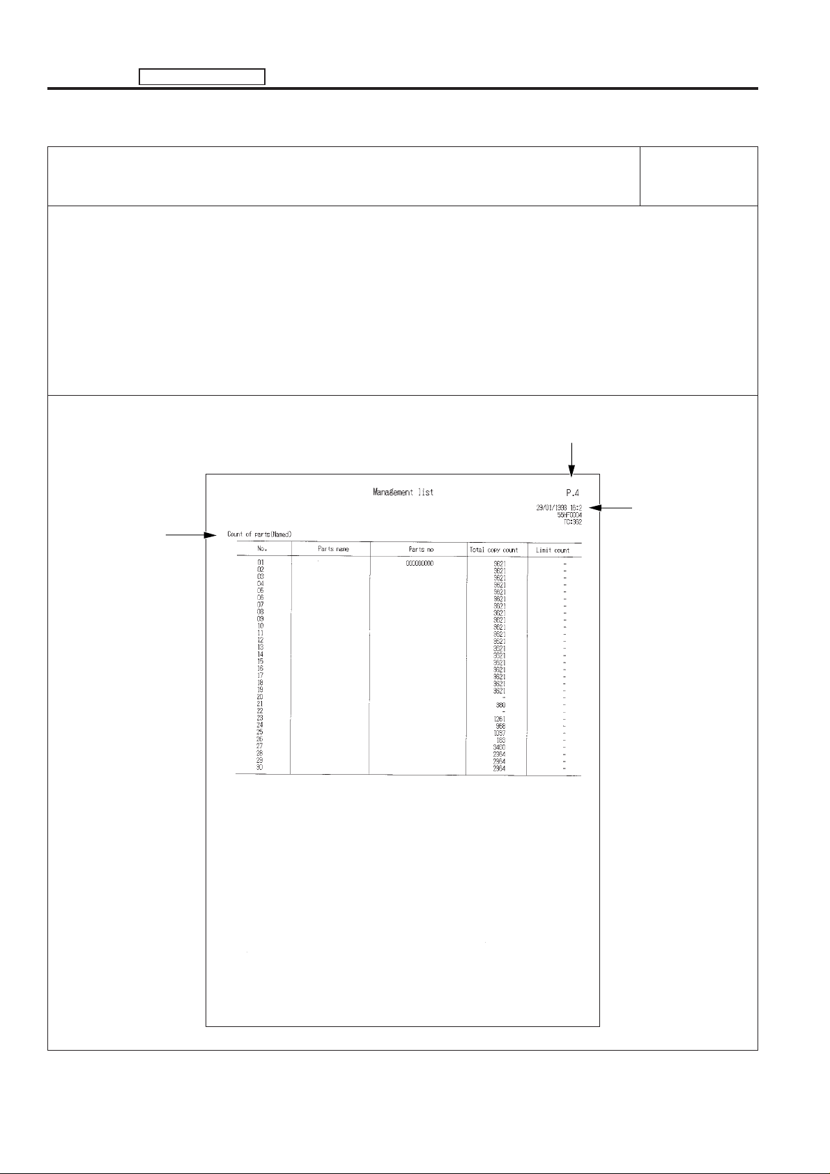
ADJUSTMENT MANAGEMENT LIST
Management list P. 4
[Description items]
• Copy count of parts (parts to be replaced (Named; arbitrarily))
Parts name, parts number, copy count and limit value of each part.
Management list
Number of page
Copy count of each
parts (parts to be
replaced (Named;
arbitrarily))
Output date, main
body serial number,
and total copy count
5 - 86
Page 89
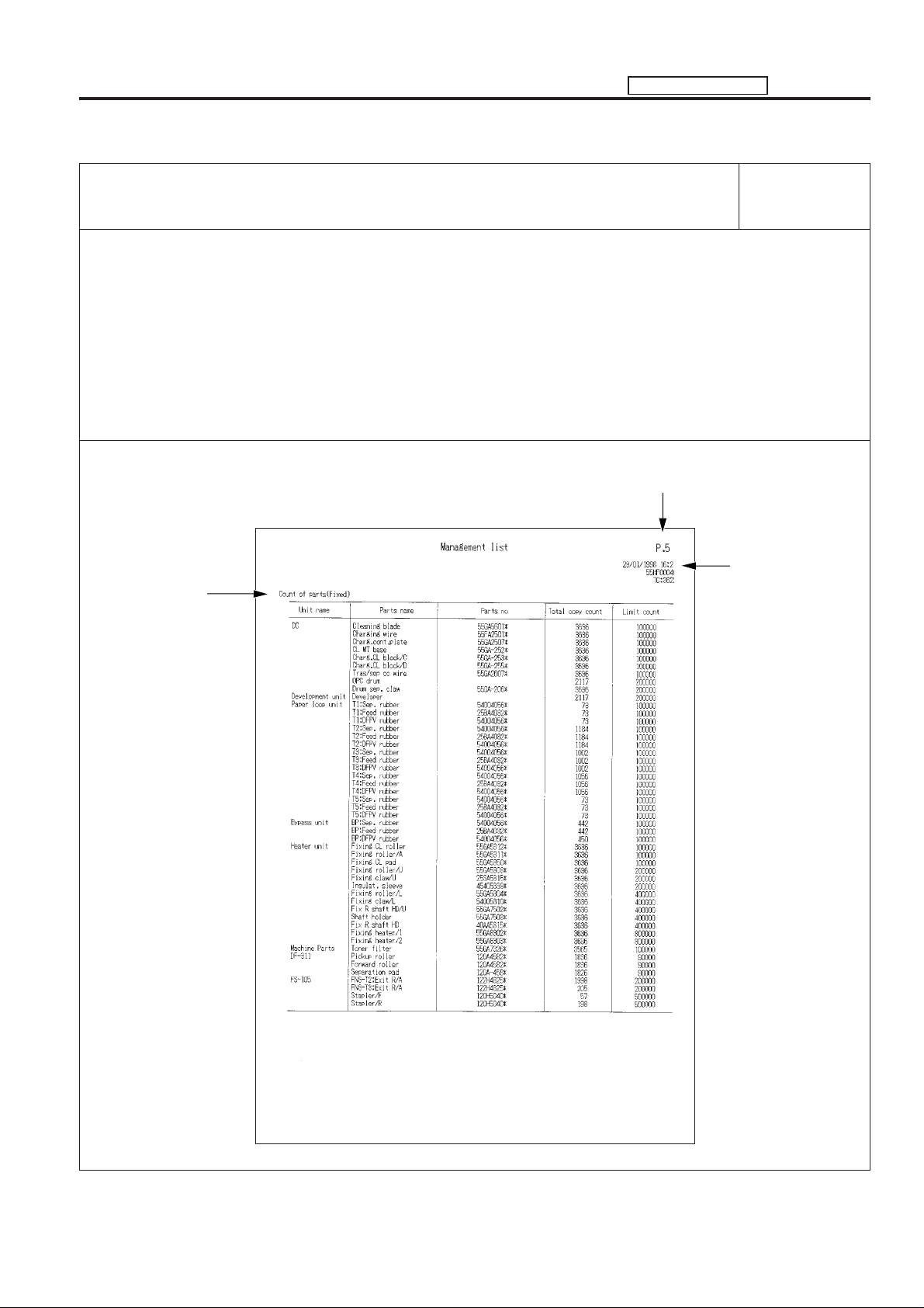
MANAGEMENT LIST ADJUSTMENT
Management list P. 5
[Description items]
• Copy count of parts (parts to be replaced (Fixed))
Parts name, Parts number, copy count and limit value of each unit.
Management list
Number of page
Copy count of each
parts (parts to be
replaced (Fixed))
Output date, main
body serial number,
and total copy count
5 - 87
Page 90
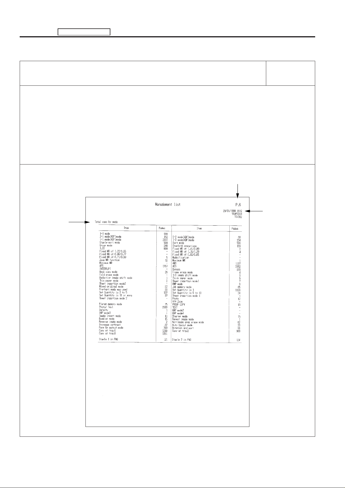
ADJUSTMENT MANAGEMENT LIST
Management list P. 6
[Description items]
• Copy count of each copy mode (Data collection 3)
Management list
Number of page
Copy count of each
copy mode
Output date, main
body serial number,
and total copy count
5 - 88
Page 91
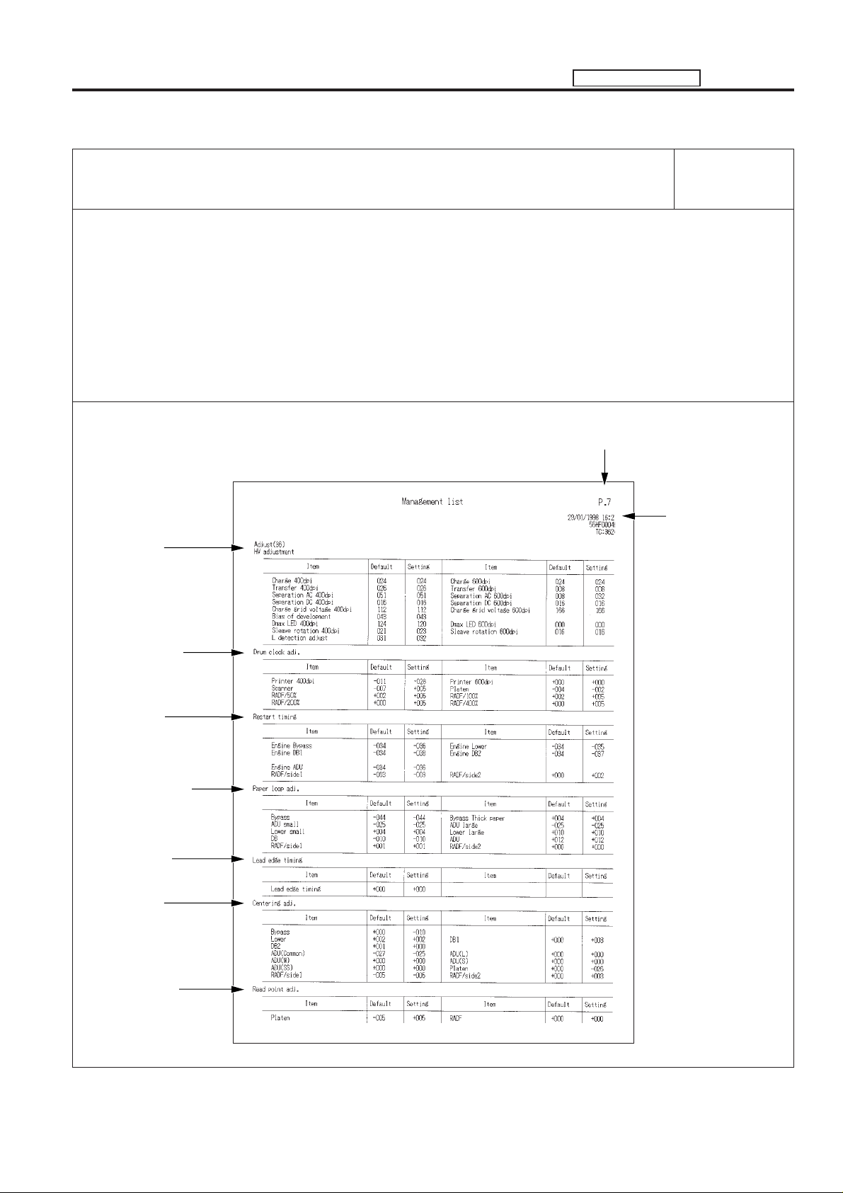
MANAGEMENT LIST ADJUSTMENT
Management list P. 7
[Description items]
• Adjustment value (36 mode)
Default values and setting values of the High voltage adjustment, Vertical/Horizontal magnification
adjustment, restart timing adjustment, paper feed loop amount adjustment, leading edge original erasure
adjustment, centering adjustment and image read point adjustment.
* Adjustment list Page 1.
Management list
Number of page
High voltage
adjustment
Vertical/Horizontal
magnification
adjustment
Restart timing
adjustment
Paper feed loop
amount adjustment
Leading edge
original erasure
adjustment
Centering
adjustment
Output date, main
body serial number,
and total copy count
Image read point
adjustment
5 - 89
Page 92
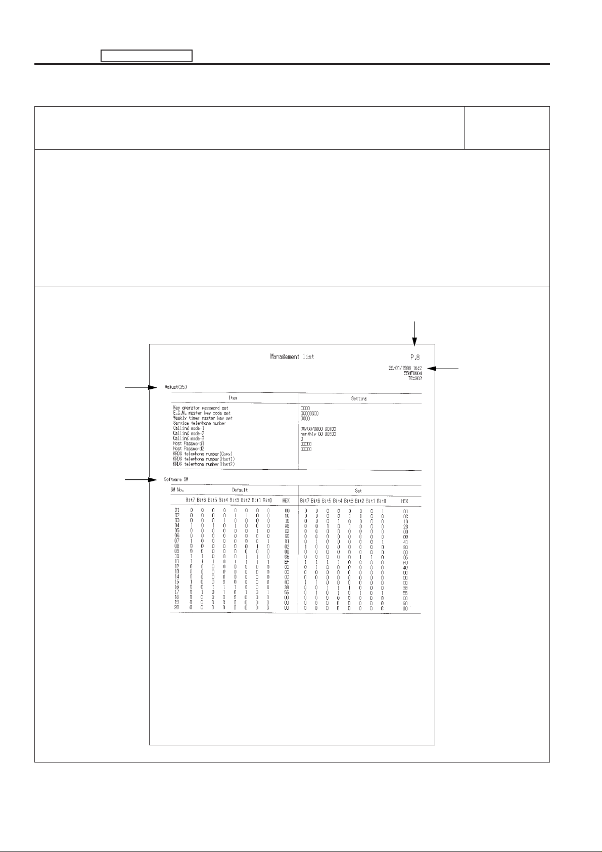
ADJUSTMENT MANAGEMENT LIST
Management list P. 8
[Description items]
• Adjustment value (25 mode)
Setting values of each adjustment item.
• Software SW setting
Default values and setting values of each DIPSW.
* Adjustment list Page 2.
Management list
Number of page
Adjustment values
(25 mode)
Software SW
settings
Output date, main
body serial number,
and total copy count
5 - 90
Page 93
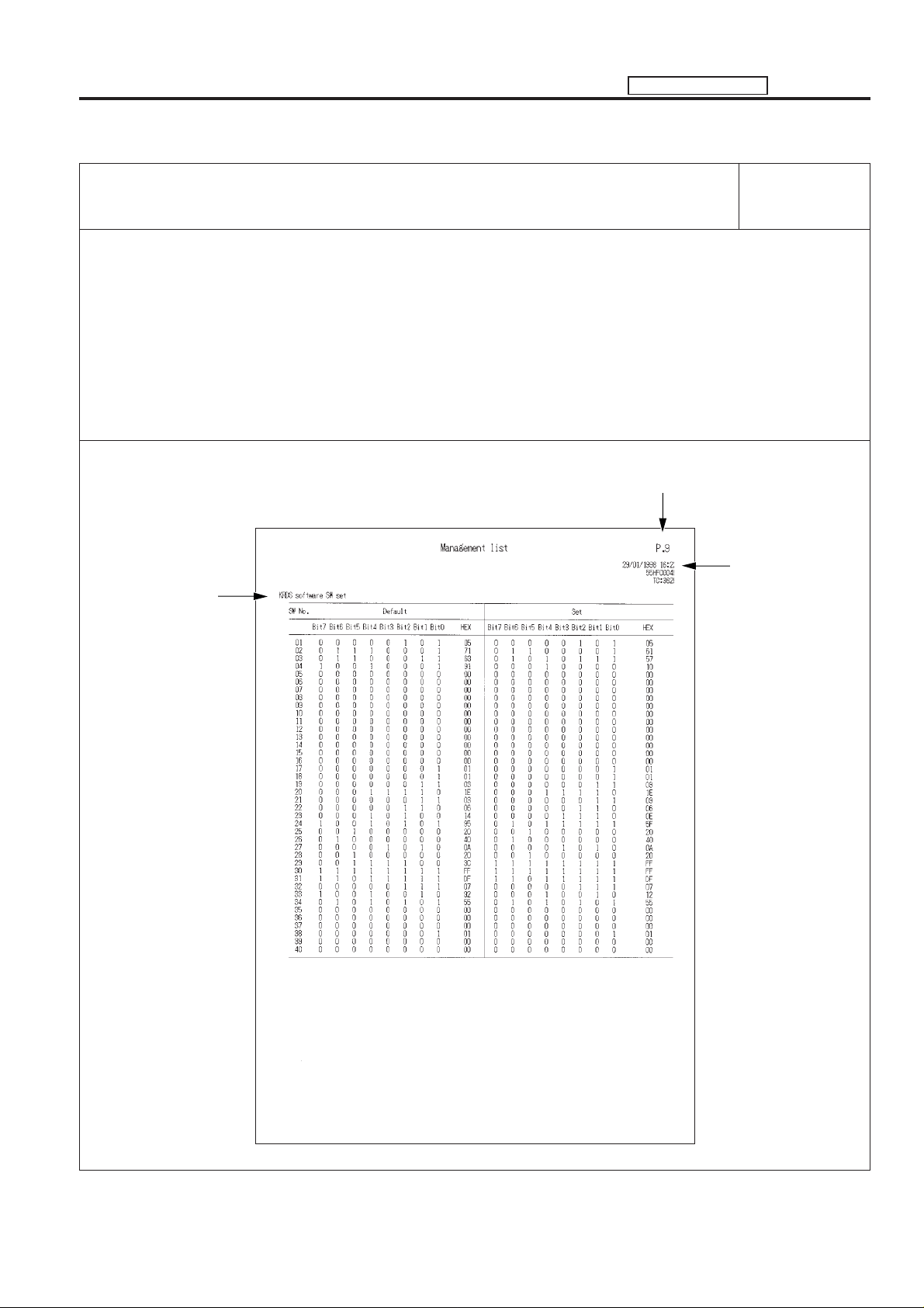
MANAGEMENT LIST ADJUSTMENT
Management list P. 9
[Description items]
• KRDS Software SW setting
Default values and setting values of each DIPSW.
Management list
Number of page
KRDS Software SW
setting
Output date, main
body serial number,
and total copy count
5 - 91
Page 94
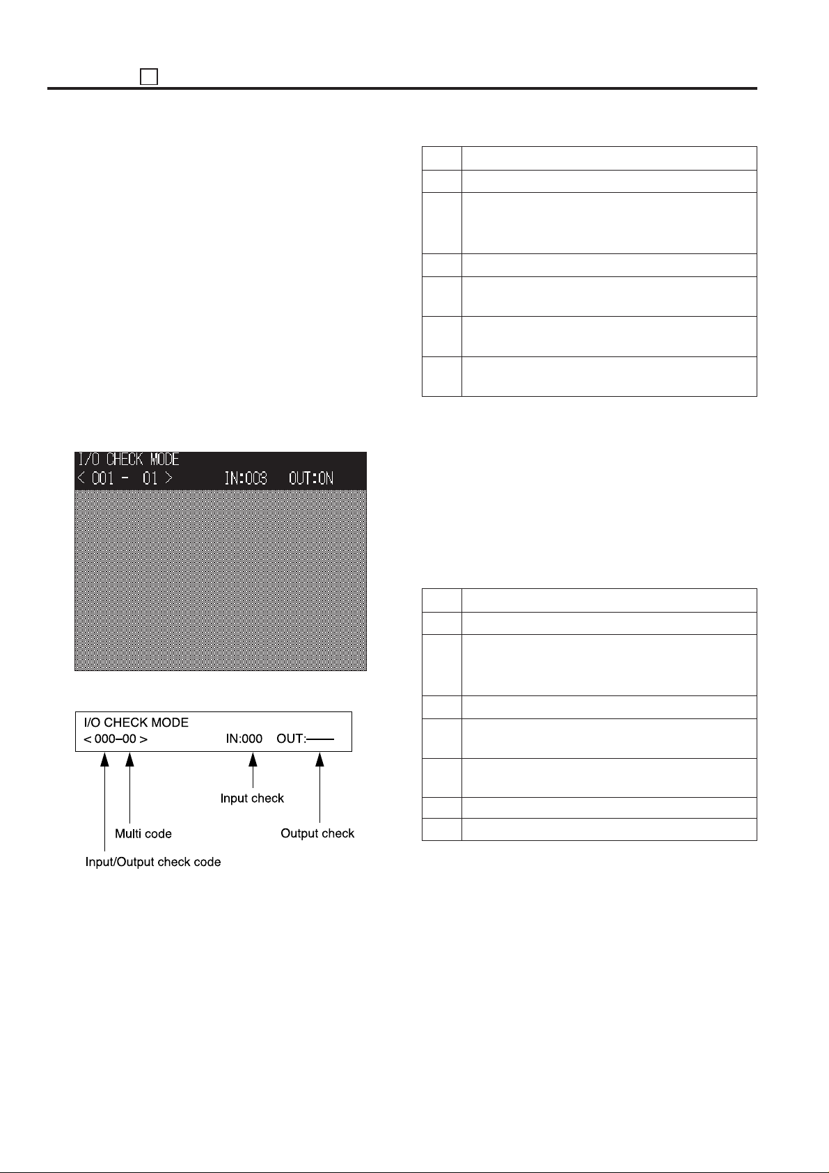
ADJUSTMENT 47
47 MODE
[1] 47 Mode Setting Method
1. 47 mode
This mode provides self-diagnostic functions (input/output
check function) to check and adjust the various signals and
loads.
Also, 47 mode has a multi-mode, it is possible to check the
multiple input/output using one input/output check code.
2. Operation method (To start 47 mode)
(1) 47 mode startup
a. Turn OFF the SW2 (sub power) when the SW1 (main
power) remains ON.
b. Turn the SW2 (sub power) back on while holding down 4
and 7 of the copy quantity setting buttons. 47 mode
screen will appear on the LCD screen.
This is the 47 mode which the normal copy operation
becomes disable.
[47 mode menu screen]
Step Operation procedure
1 Enter the 47 mode.
2 [47 mode menu screen]
Using the copy quantity setting button, enter the input
check code . (*1)
3 When using the multi mode, press the P button.
4 Using the copy quantity setting button, enter the multi
code . (*1)
5 Input check result will appear in the input check result
display area.
6 To check other signal input check, repeat steps 2 to
5.
*1: Refer to “[7] Input check (code) list”.
(3) Output check method
a. Using the copy quantity setting button, enter the output
check code for the desired output load to check.
b. When use the multi mode, press P button and enter the
multi code according to the desired output check item
(load).
c. Press the Start print button to perform the output check.
d. To end the output check, press the Stop/Clear button.
[47 mode message display area]
(2) Input check method
a. Using the copy quantity setting button, enter the code
input for the desired signal (sensor, etc.) to check.
b. When using the multi mode, press P button and enter the
multi code according to the desired input check item
(signal) with the copy quantity setting button.
Step Operation procedure
1 Enter the 47 mode.
2 [47 mode menu screen]
Using the copy quantity setting button, enter the
output check code . (*2)
3 When using the multi mode, press the P button.
4 Using the copy quantity setting button, enter the multi
code . (*2)
5 Press the Start print button to perform the output
check.
6 To end the output check, press the Stop/Clear button.
7 To make another output check, repeat steps 2 to 6.
*2: Refer to “[8] Output check (code) list”.
(4) Exiting the 47 mode
To end the 47 mode, turn off the SW2 (sub power).
5 - 92
Page 95
47 ADJUSTMENT
[2] Initial Setting in the field
Each adjustment data is totally returned to the data value when
the machine is delivered from the factory.
Step Operation procedure
1 Enter the 47 mode.
2 [47 mode menu screen]
Press “93” by means of the copy quantity setting
button.
Check that “093-00” appears in the message display
area.
3 Press the Start print button. (*1)
3
The message display column [NOW] display changes
to [FIN] and resets and ends.
4 To end the setting, press the Stop/Clear button.
5 To end the 47 mode, turn off the SW2 (sub power).
*1: It may be necessary to change the language in both 25
mode and key operator mode after performing the initial
setting.
[3] Drum count reset
When replacing the drum, perform this operation to reset the
copy count of drum.
Step Operation procedure
1 Enter the 47 mode.
2 [47 mode menu screen]
Press “91” by means of the copy quantity setting
button.
Check that “091-00” appears in the message display
area.
3 Press the P button.
4 Press “1” by means of the copy quantity setting
button.
Check that “091-01” appears in the message display
area.
5 Press the Start print button.
3
The message display column [NOW] display changes
to [FIN] and resets and ends.
6 To end the operation, press the Stop/Clear button.
7 To end the 47 mode, turn off the SW2 (sub power).
[4] RADF original size detection
3
adjustment
Perform this adjustment when the RADF original size detection
does not operate properly or when replacing the DF control
board.
Step Operation procedure
1 Enter the 47 mode.
2 [47 mode menu screen]
Press “69” by means of the copy quantity setting
button.
Check that “069-00” appears in the message display
area.
3 Set the A5R size original on the RADF, then press the
Start print button.
4 Press the Stop/Clear button.
5 Press the P button.
6 Press “1” by means of the copy quantity setting
button.
Check that “069-01” appears in the message display
area.
7 Set the A3 size original on the RADF, then press the
Start print button.
8 To end the adjustment, press the Stop/Clear button.
9 To end the 47 mode, turn off the SW2 (sub power).
MODEL
7040
MANUAL
SERVICE HANDBOOK
REVISED EDITION
5 - 93
3
DATE
Mar. 1999
PAGE
5-93
METHOD
REPLACEMENT
Page 96
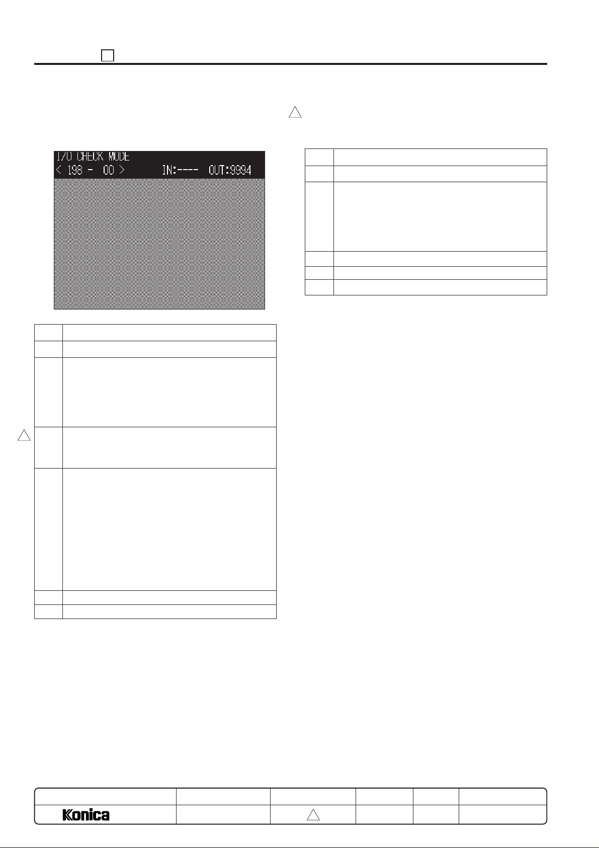
ADJUSTMENT 47
[5] Electrical RDH memory check
Perform this adjustment when memory is expanded.
[ Electrical RDH memory check screen ]
Step Operation procedure
1 Enter the 47 mode.
2 [47 mode menu screen]
Press “198” by means of the copy quantity setting
button.
Check that “198-00” appears in the message display
area.
3 When the START button is pressed, the message
3
display column "OUT:" changes to "NOW" and a
memory check is initiated. (approx. 1 min) (*1)
4 The output value according to the expanded memory
is displayed in the item of the message display area
“OUT: ”.
Expansion memory capacity : Output value
0 MB : 9994
16 MB : 9995
32 MB : 9996
48 MB : 9997
64 MB : OK
5 To end the check, press the Stop/Clear button.
6 To end the 47 mode, turn off the SW2 (sub power).
*1: Do not press the Start print button twice or more.
[6] RADF Sensor Adjustment
3
Perform this adjustment when replacing the DF control board.
Step Operation procedure
1 Enter the 47 mode.
2 [47 mode menu screen]
Press “69 P 2” by means of the copy quantity setting
button.
Check that “069-02” appears in the message display
area.
3 Press the Start print button. (*1)
4 To end the setting, press the Stop/Clear button.
5 To end the 47 mode, turn off the SW2 (sub power).
MODEL
7040
MANUAL
SERVICE HANDBOOK
REVISED EDITION
5 - 94
3
DATE
Mar. 1999
PAGE
5-94
METHOD
REPLACEMENT
Page 97
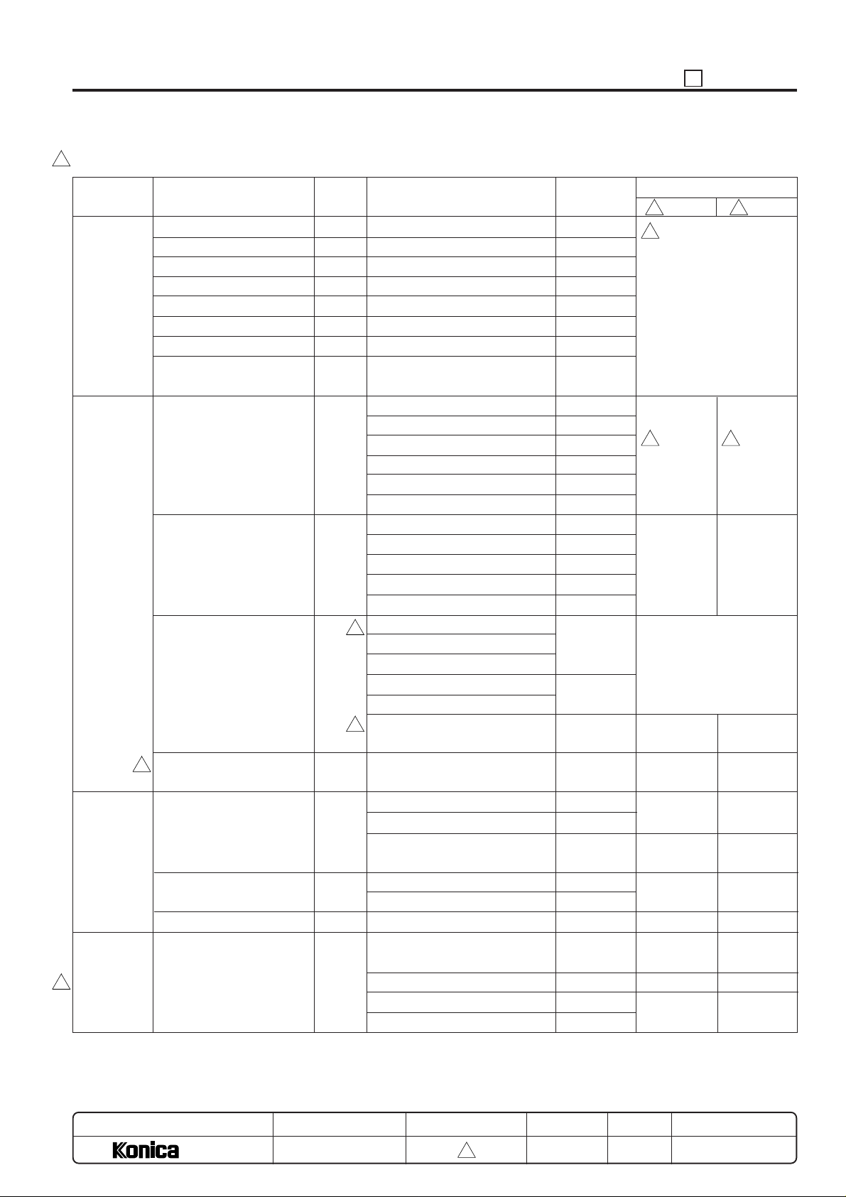
[7] Input check (code) list
3
47 ADJUSTMENT
Classification
Analog
signal
Paper feed
Paper feed/
Conveyance
Optics
3
Name
Drum temperature signal
Toner control data 0
Toner control data 1
Fixing temperature sensor 0
Fixing temperature sensor 1
L detection signal
Humidity sensor signal
By-pass paper size
detection signal
No paper detection signal
Tray upper limit detection
signal
Paper size signal
Paper feed door open/close
3
detection signal
Paper feed sensor signal
Paper feed exit sensor signal
Interlock
Optics sensor signal
Code
00
01
02
03
04
05
06
07
10
12
16
17
20
22
23
40
Multi code
1: Main body upper tray
2: Main body lower tray
3: DB1
4: DB2
DB3 (only for DB-208 is installed)
5:
6: By-pass
1: Main body upper tray
2: Main body lower tray
3: DB1
4: DB2
DB3 (only for DB-208 is installed)
5:
1: Main body upper tray
3
2: Main body lower tray
3: DB1
4: DB2 (only for DB-208)
5: DB3 (only for DB-208)
6: By-pass feed tray paper size
3
detection PS
1: No feed PS
2: Regist. PS
3: Paper feed detect (DB paper
feed door open/close detect)
1: Fixing exit PS
2: Paper exit PS
1: Front door
0: Optics home position PS
1: APS timing PS
2: APS sensor 1
3: APS sensor 2
Symbol
PRDB
PRDB
TH1
TH2
HUM1
VR1
PS33
PS31
PS402
PS404
PS406
PS13
PS34
PS32
PS403
PS405
PS407
SW101, 102,
103, 104
SW401, 402,
403, 404
PS27
PS14
PS17
PS16
PS401
PS29
PS1
MS1
PS3
PS4
PS25
PS26
Display
OFF
3 3
3
ON
Analog value (0 to 255)
3
Paper
Upper limit
not reached
3
No paper
Upper limit
Display of each paper size
2:F4R, 3:B5R, 4:A5, 6:A4R,
7:A5R, 8:A3, 9:B4, 10:B6R,
11: Post card, 13:B5, 15:A4,
17:8.4X14, 21:8.5X11R,
22:5.5X8.5, 23:5.5X8.5R,
24:11X17, 31:8.5X11
No paper
Close
No paper
No paper (Door
is closed)
No paper
Close
Not in home
position
Open
No paper
Paper
Open
Paper
Paper (Door
is opened)
Paper
Open
In home
position
Close
Paper
MODEL
7040
MANUAL
SERVICE HANDBOOK
REVISED EDITION
5 - 95
3
DATE
Mar. 1999
PAGE
5-95
METHOD
REPLACEMENT
Page 98
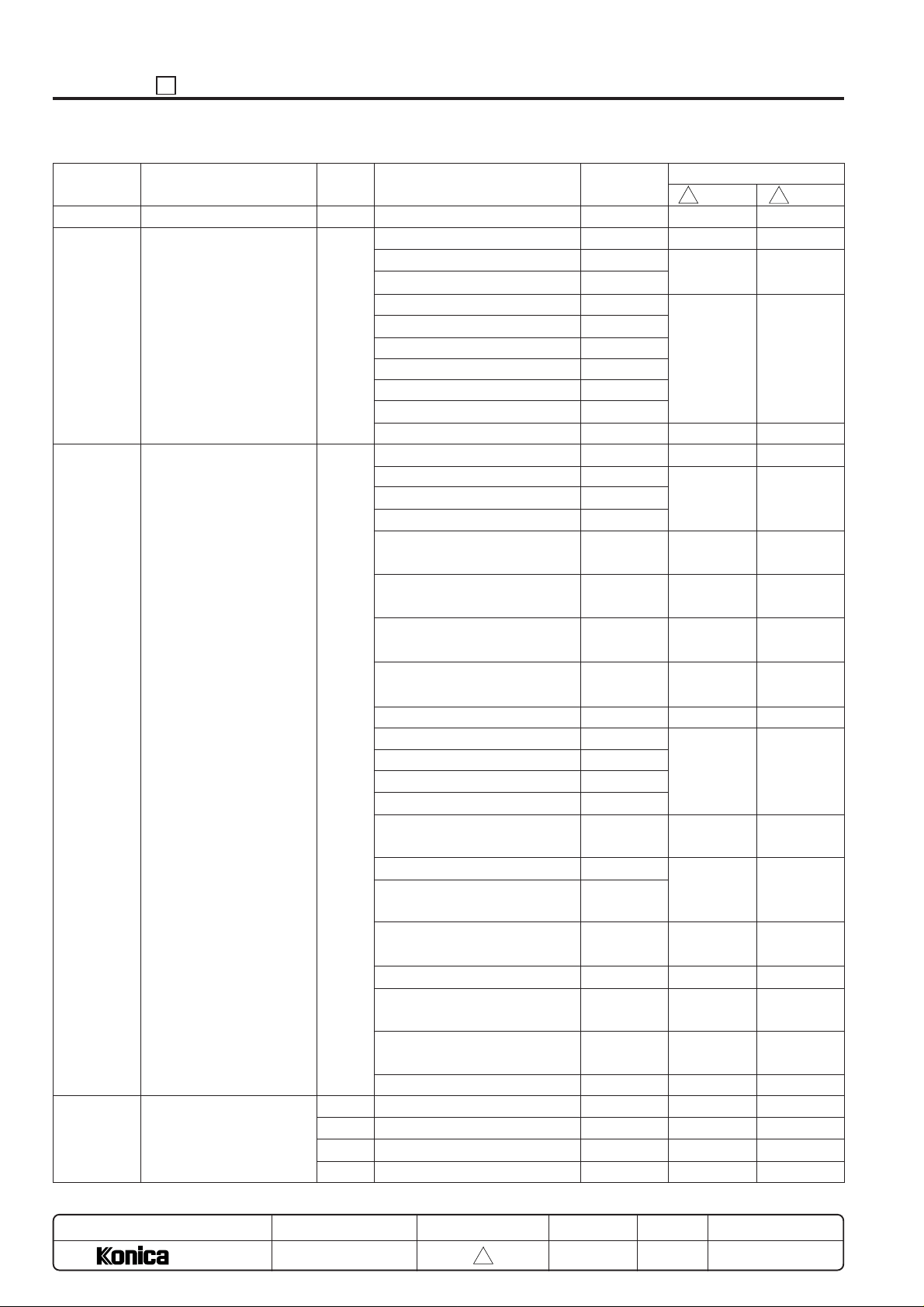
ADJUSTMENT 47
Classification
Intrinsic function
RADF
Finisher
ADU/Reversal
Name
Toner level detection signal
RADF input
Finisher input
Code
57
60
70
80
81
82
83
Multi code
00: No original detect PS
01: RADF open/close detect PS
02: Cover open/close detect PS
03: Original regist. PS
04: Original feed detect PS
05: Original reversal detect PS
06: Original exit detect PS
07: Original size detect PS 1
08: Original size detect PS 2
09: Original size detect VR 1
Conveyance drum position detect PS
00:
01:
Conveyance drum entrance detect PS
02: Tray 1 paper exit detect PS
03: Paper through detect PS
04: Tray upper limit detect PS
05: Tray lower limit detect PS
06: Tray 2 full-stack detect PS
08: Tray 3 full-stack detect PS
11: Stapler no paper detect PS
12: Paper exit motor HP PS
13: Stapler unit HP PS
Alignment motor HP PS (front)
14:
15:
Alignment motor HP PS (rear)
16: Stapler HP PS (front)
17: No staple PS (front)
18: Staple leading edge detect
PS (front)
19: Stapler HP PS (rear)
20: No staple PS (rear)
21: Staple leading edge detect
PS (rear)
22: Inter lock MS
23: Stapler safety MS
Reversal detect PS1
Reversal detect PS2
ADU regist. PS
ADU set detect PS
Symbol
TDL
PS305
PS301
MS301
PS306
PS308
PS309
PS307
PS302
PS303
VR301
PS801
PS802
PS803
PS804
PS805
PS806
PS807
PS809
PS812
PS813
PS814
PS816
PS815
PS817
PS818
PS820
PS821
MS801
MS804
PS28
PS30
PS502
Display
OFF
3
No toner
No paper
Close
No paper
OFF
No paper
Upper limit
not reached
Lower limit
not reached
Full-stack not
reached
Full-stack not
reached
Paper
Not in home
position
In home
position
Staple
In home
position
Staple
Set (ON)
OFF
No paper
Paper
No paper
ADU is released
ON
3
Toner
Paper
Open
Paper
ON
Paper
Upper limit
Lower limit
Full-stack
Full-stack
No paper
In home
position
Not in home
position
No staple
Not in home
position
No staple
Finisher is
released (OFF)
ON
Paper
No paper
Paper
ADU is set
MODEL
7040
MANUAL
SERVICE HANDBOOK
REVISED EDITION
5 - 96
3
DATE
Mar. 1999
PAGE
5-96
METHOD
REPLACEMENT
Page 99
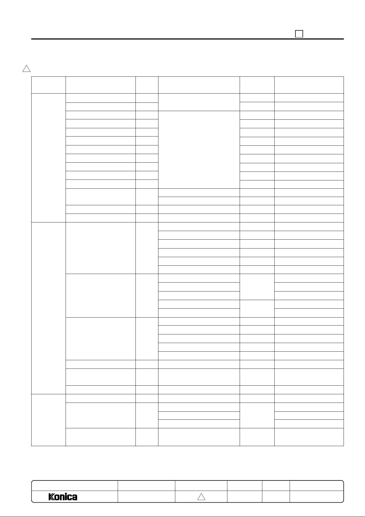
[8] Output check (code) list
3
47 ADJUSTMENT
Classification
Analog
signal
Paper feed
Optics
Name
Exposure lamp
Toner supply motor 1
Charging
Transfer
Separation (AC)
Transfer + separation (AC+DC)
Separation (DC)
Grid
Dmax/ γ LED
Guide plate
Bias
Service counter clear
Dmax level auto adjustment
PWM γ correction
1st paper feed SD
1st paper feed motor
Tray motor
Registration clutch
By-pass tray paper size
detect VR
Separation claw SD
Scanner drive motor
Polygon motor
Code
00
01
02
03
04
05
06
07
08
10
11
15
18
19
20
21
23
25
28
29
31
32
Multi code
Output the code specified value
as reading.
1: Service counter clear
98: KRDS initializing
1: Main body upper tray
2: Main body lower tray
3: By-pass
4: DB1
5: DB2
6: DB3
1: Main body 210 mm/sec.
2: Main body 179 mm/sec.
3: Main body 630 mm/sec.
5: DB low speed 210 mm/sec.
6: DB high speed 570 mm/sec.
1: Main body upper tray
2: Main body lower tray
3: DB1
4: DB2
5: DB3
1: 400 dpi
2: 600 dpi
3: Wait
Symbol
L1
M3, M11
HV1
HV2
HV2
HV2
HV2
HV1
HV2
HV2
SD3
SD2
SD4
SD401
SD402
SD403
M6
M401
M9
M8
M402
M403
M404
MC1
VR1
SD1
M2
M5
Inhabit to set/change to
write in the filed
X
X
X
X
X
Adjust by the 36 mode.
Adjust by the 36 mode.
X
X
Adjust by the 36 mode.
Adjust by the 36 mode.
X
Laser PWM
MODEL
7040
36
as reading.
MANUAL
SERVICE HANDBOOK
REVISED EDITION
5 - 97
3
DATE
Mar. 1999
PAGE
5-97
METHOD
REPLACEMENT
Page 100
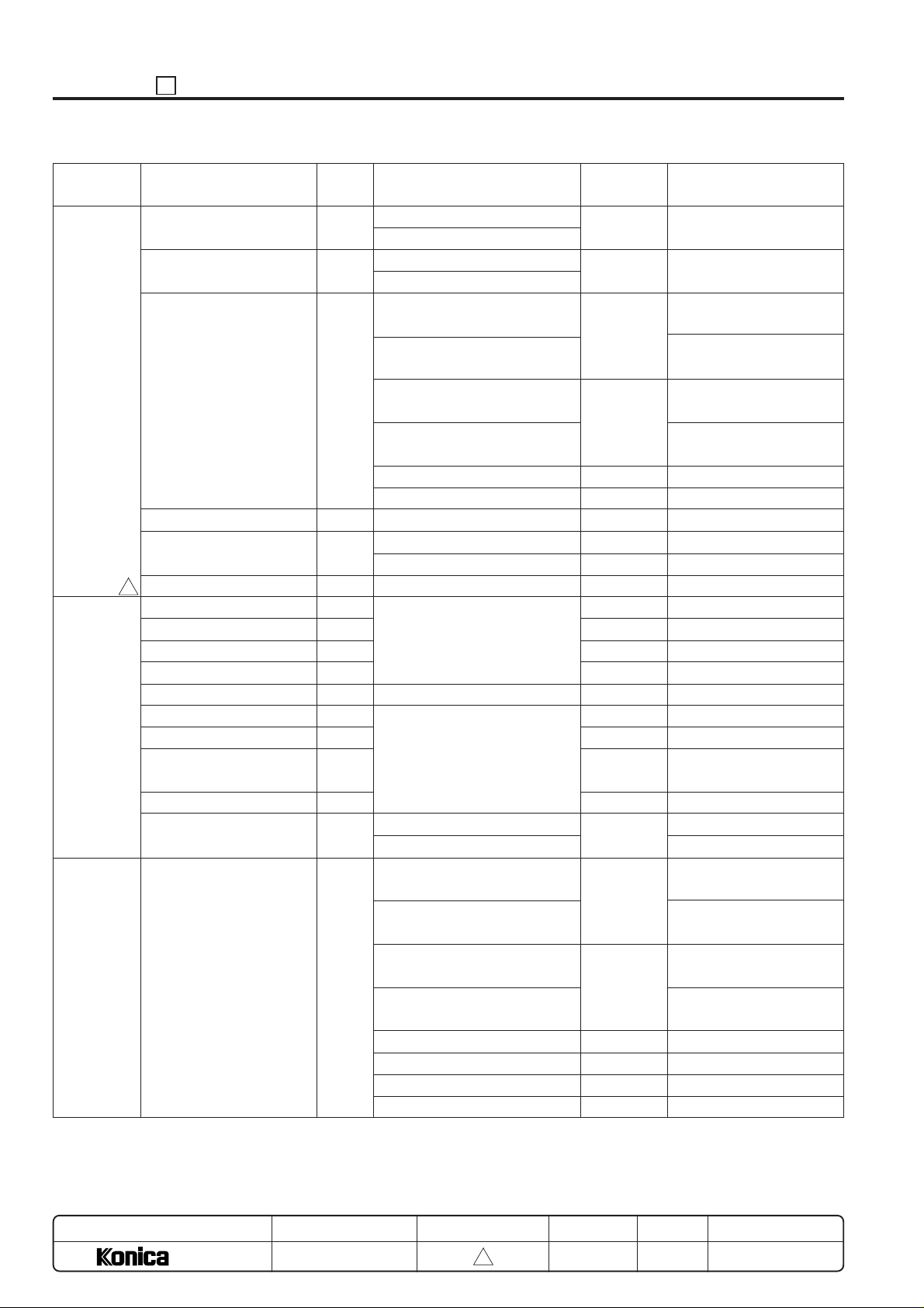
ADJUSTMENT 47
Classification
Main body
3
Intrinsic
function
RADF
Name
Conveyance motor
Drum motor
Fan motor
Total counter
Fixing heater lamp
All operation unit LEDs lit.
Developing drive motor
PCL
TSL
Agitation motor
Toner auto supply
Toner supply motor
Developing MC
Toner level detect power
source
Toner cartridge
24 V power source remote
Load output
Code
40
41
42
43
45
48
50
51
52
53
54
55
56
57
58
59
60
Multi code
1: 400 dpi
2: 600 dpi
1: 400 dpi
2: 600 dpi
1: Main body cooling fan (low
speed)
2: Main body cooling fan (high
speed)
3: Conveyance suction fan (low
speed)
4: Conveyance suction fan
(high speed)
5: DCPS cooling fan
6: Scanner cooling fan 1, 2
1: Main heater
2: Sub heater
1: for scanner
2: for printer
0: Original feed motor (forward
rotation)
1: Original feed motor (reverse
rotation)
2: Original conveyance motor
(forward rotation)
3: Original conveyance motor
(reverse rotation)
4: Original pick-up CL
5: Original feed CL
6: Flapper SD
7: Original pressure SD
Symbol
M1
M4
FM3
FM4
FM5
FM1,FM2
C(T)
L2
L3
M3,MC2
PCL
TSL
M3
M11
M11
MC2
TLD
M10
DCPS1
M302
M301
CL301
CL302
SD301
SD302
Inhabit to set/change to
write in the filed
Adjust by the 36 mode.
MODEL
7040
MANUAL
SERVICE HANDBOOK
REVISED EDITION
5 - 98
3
DATE
Mar. 1999
PAGE
5-98
METHOD
REPLACEMENT
 Loading...