

Page 1

Table of Contents
Overview . . . . . . . . . . . . . . . . . . . . . . . . . . . . . . . . . . . . . . . . . . . . . . . . . . . . . . . . . . . .8
About This Manual . . . . . . . . . . . . . . . . . . . . . . . . . . . . . . . . . . . . . . . . . . . . . . . . . . . . . . . . . . . .8
Introduction . . . . . . . . . . . . . . . . . . . . . . . . . . . . . . . . . . . . . . . . . . . . . . . . . . . . . . . . . . . . . . . . . .9
Features . . . . . . . . . . . . . . . . . . . . . . . . . . . . . . . . . . . . . . . . . . . . . . . . . . . . . . . . . . . . . . . . . . .11
System Requirements . . . . . . . . . . . . . . . . . . . . . . . . . . . . . . . . . . . . . . . . . . . . . . . . . . . . . . . .12
When in Portable Mode . . . . . . . . . . . . . . . . . . . . . . . . . . . . . . . . . . . . . . . . . . . . . . . . . . 12
When Connected to a MACINTOSH . . . . . . . . . . . . . . . . . . . . . . . . . . . . . . . . . . . . . . . . 12
When Connected to a PC. . . . . . . . . . . . . . . . . . . . . . . . . . . . . . . . . . . . . . . . . . . . . . . . . 13
Electromagnetic Emissions . . . . . . . . . . . . . . . . . . . . . . . . . . . . . . . . . . . . . . . . . . . . . . . . . . . .14
Japan . . . . . . . . . . . . . . . . . . . . . . . . . . . . . . . . . . . . . . . . . . . . . . . . . . . . . . . . . . . . . . . . 14
Taiwan . . . . . . . . . . . . . . . . . . . . . . . . . . . . . . . . . . . . . . . . . . . . . . . . . . . . . . . . . . . . . . . 14
European Union (EU) . . . . . . . . . . . . . . . . . . . . . . . . . . . . . . . . . . . . . . . . . . . . . . . . . . . . 15
USA . . . . . . . . . . . . . . . . . . . . . . . . . . . . . . . . . . . . . . . . . . . . . . . . . . . . . . . . . . . . . . . . . 15
About the DCS Pro Back Plus . . . . . . . . . . . . . . . . . . . . . . . . . . . . . . . . . . . . . . . . . . .16
Overview . . . . . . . . . . . . . . . . . . . . . . . . . . . . . . . . . . . . . . . . . . . . . . . . . . . . . . . . . . . . . . . . . .16
Rear . . . . . . . . . . . . . . . . . . . . . . . . . . . . . . . . . . . . . . . . . . . . . . . . . . . . . . . . . . . . . . . . . 16
Front (Attaches to Camera Body). . . . . . . . . . . . . . . . . . . . . . . . . . . . . . . . . . . . . . . . . . . 16
Sides. . . . . . . . . . . . . . . . . . . . . . . . . . . . . . . . . . . . . . . . . . . . . . . . . . . . . . . . . . . . . . . . . 17
Top . . . . . . . . . . . . . . . . . . . . . . . . . . . . . . . . . . . . . . . . . . . . . . . . . . . . . . . . . . . . . . . . . . 18
Imager . . . . . . . . . . . . . . . . . . . . . . . . . . . . . . . . . . . . . . . . . . . . . . . . . . . . . . . . . . . . . . . . . . . .18
Focus Screen Overlay . . . . . . . . . . . . . . . . . . . . . . . . . . . . . . . . . . . . . . . . . . . . . . . . . . . . . . . .19
Applying an Overlay . . . . . . . . . . . . . . . . . . . . . . . . . . . . . . . . . . . . . . . . . . . . . . . . . . . . . 19
Contents
Back
Next
Index
Contents-1
Page 2

Table of Contents
IR Filter . . . . . . . . . . . . . . . . . . . . . . . . . . . . . . . . . . . . . . . . . . . . . . . . . . . . . . . . . . . . . . . . . . .20
Anti-aliasing Filter . . . . . . . . . . . . . . . . . . . . . . . . . . . . . . . . . . . . . . . . . . . . . . . . . . . . . . . . . . . .20
Removing an IR or Anti-aliasing Filter . . . . . . . . . . . . . . . . . . . . . . . . . . . . . . . . . . . . . . . 21
Inserting a Filter . . . . . . . . . . . . . . . . . . . . . . . . . . . . . . . . . . . . . . . . . . . . . . . . . . . . . . . . 21
Image LCD . . . . . . . . . . . . . . . . . . . . . . . . . . . . . . . . . . . . . . . . . . . . . . . . . . . . . . . . . . . . . . . . .22
How the Image LCD Works . . . . . . . . . . . . . . . . . . . . . . . . . . . . . . . . . . . . . . . . . . . . . . . 22
Turning the Image LCD On and Off . . . . . . . . . . . . . . . . . . . . . . . . . . . . . . . . . . . . . . . . . 23
Tilting the Image LCD. . . . . . . . . . . . . . . . . . . . . . . . . . . . . . . . . . . . . . . . . . . . . . . . . . . . 23
Menu Bar . . . . . . . . . . . . . . . . . . . . . . . . . . . . . . . . . . . . . . . . . . . . . . . . . . . . . . . . . . . . . 24
Menus. . . . . . . . . . . . . . . . . . . . . . . . . . . . . . . . . . . . . . . . . . . . . . . . . . . . . . . . . . . . . . . . 25
Status Screen . . . . . . . . . . . . . . . . . . . . . . . . . . . . . . . . . . . . . . . . . . . . . . . . . . . . . . . . . . . . . . .27
Displaying the Status screen . . . . . . . . . . . . . . . . . . . . . . . . . . . . . . . . . . . . . . . . . . . . . . 27
Digital Buttons . . . . . . . . . . . . . . . . . . . . . . . . . . . . . . . . . . . . . . . . . . . . . . . . . . . . . . . . . . . . . .28
Four-way Switch. . . . . . . . . . . . . . . . . . . . . . . . . . . . . . . . . . . . . . . . . . . . . . . . . . . . . . . . 28
Menu Button . . . . . . . . . . . . . . . . . . . . . . . . . . . . . . . . . . . . . . . . . . . . . . . . . . . . . . . . . . . 28
OK Button. . . . . . . . . . . . . . . . . . . . . . . . . . . . . . . . . . . . . . . . . . . . . . . . . . . . . . . . . . . . . 28
Cancel Button. . . . . . . . . . . . . . . . . . . . . . . . . . . . . . . . . . . . . . . . . . . . . . . . . . . . . . . . . . 28
Quick Guide for Using the Image LCD and Digital Buttons . . . . . . . . . . . . . . . . . . . . . . . . . . . .29
Power Button . . . . . . . . . . . . . . . . . . . . . . . . . . . . . . . . . . . . . . . . . . . . . . . . . . . . . . . . . . . . . . .30
Ports and Jacks . . . . . . . . . . . . . . . . . . . . . . . . . . . . . . . . . . . . . . . . . . . . . . . . . . . . . . . . . . . . .31
Lens Sync Cable Jack . . . . . . . . . . . . . . . . . . . . . . . . . . . . . . . . . . . . . . . . . . . . . . . . . . . 31
IEEE 1394 Port. . . . . . . . . . . . . . . . . . . . . . . . . . . . . . . . . . . . . . . . . . . . . . . . . . . . . . . . . 31
Flash Sync Cable Jack. . . . . . . . . . . . . . . . . . . . . . . . . . . . . . . . . . . . . . . . . . . . . . . . . . . 31
Contents
Back
Next
Index
Contents-2
Page 3

Table of Contents
Battery Connection Jack. . . . . . . . . . . . . . . . . . . . . . . . . . . . . . . . . . . . . . . . . . . . . . . . . . 31
Remote Shutter Release Port. . . . . . . . . . . . . . . . . . . . . . . . . . . . . . . . . . . . . . . . . . . . . . 32
S-Video Output Port . . . . . . . . . . . . . . . . . . . . . . . . . . . . . . . . . . . . . . . . . . . . . . . . . . . . . 32
The Basics . . . . . . . . . . . . . . . . . . . . . . . . . . . . . . . . . . . . . . . . . . . . . . . . . . . . . . . . . .33
Assembling the Camera . . . . . . . . . . . . . . . . . . . . . . . . . . . . . . . . . . . . . . . . . . . . . . . . . . . . . . .33
Connecting the DCS Pro Back Plus to the Camera Body and Accessories . . . . . . . . . . . . . . . .34
MAMIYA Interface Plate . . . . . . . . . . . . . . . . . . . . . . . . . . . . . . . . . . . . . . . . . . . . . . . . . . 34
Connecting the DCS Pro Back Plus to the Camera Body . . . . . . . . . . . . . . . . . . . . . . . . 35
Disconnecting the DCS Pro Back Plus from the Camera Body . . . . . . . . . . . . . . . . . . . . 37
Connecting the Camera Lens. . . . . . . . . . . . . . . . . . . . . . . . . . . . . . . . . . . . . . . . . . . . . . 38
Connecting Flash/Strobe Units. . . . . . . . . . . . . . . . . . . . . . . . . . . . . . . . . . . . . . . . . . . . . 39
Image Files . . . . . . . . . . . . . . . . . . . . . . . . . . . . . . . . . . . . . . . . . . . . . . . . . . . . . . . . . . . . . . . . .40
Storing Images . . . . . . . . . . . . . . . . . . . . . . . . . . . . . . . . . . . . . . . . . . . . . . . . . . . . . . . . . . . . . .41
Compact Flash (CF) Cards . . . . . . . . . . . . . . . . . . . . . . . . . . . . . . . . . . . . . . . . . . . . . . . . . . . .42
Inserting a CF Card . . . . . . . . . . . . . . . . . . . . . . . . . . . . . . . . . . . . . . . . . . . . . . . . . . . . . 43
Ejecting a CF Card . . . . . . . . . . . . . . . . . . . . . . . . . . . . . . . . . . . . . . . . . . . . . . . . . . . . . . 44
Selecting a CF Card or Folder . . . . . . . . . . . . . . . . . . . . . . . . . . . . . . . . . . . . . . . . . . . . . 45
Accessing Images on a CF Card . . . . . . . . . . . . . . . . . . . . . . . . . . . . . . . . . . . . . . . . . . . 46
Formatting a CF Card. . . . . . . . . . . . . . . . . . . . . . . . . . . . . . . . . . . . . . . . . . . . . . . . . . . . 47
Recovering Data on a CF Card . . . . . . . . . . . . . . . . . . . . . . . . . . . . . . . . . . . . . . . . . . . . 48
Configuring Your Camera . . . . . . . . . . . . . . . . . . . . . . . . . . . . . . . . . . . . . . . . . . . . . .49
Contents
Back
Next
Index
Contents-3
Page 4

Table of Contents
Setting the Date and Time . . . . . . . . . . . . . . . . . . . . . . . . . . . . . . . . . . . . . . . . . . . . . . . . . . . . .49
Setting Camera Properties . . . . . . . . . . . . . . . . . . . . . . . . . . . . . . . . . . . . . . . . . . . . . . . . . . . . .50
Displaying the Properties Menu . . . . . . . . . . . . . . . . . . . . . . . . . . . . . . . . . . . . . . . . . . . . 50
Setting Battery Save Onset . . . . . . . . . . . . . . . . . . . . . . . . . . . . . . . . . . . . . . . . . . . . . . . 51
Setting Display Off Time. . . . . . . . . . . . . . . . . . . . . . . . . . . . . . . . . . . . . . . . . . . . . . . . . . 51
Total Actuations . . . . . . . . . . . . . . . . . . . . . . . . . . . . . . . . . . . . . . . . . . . . . . . . . . . . . . . . 52
Use Folder01 . . . . . . . . . . . . . . . . . . . . . . . . . . . . . . . . . . . . . . . . . . . . . . . . . . . . . . . . . . 52
Video Format . . . . . . . . . . . . . . . . . . . . . . . . . . . . . . . . . . . . . . . . . . . . . . . . . . . . . . . . . . 53
Video Signal . . . . . . . . . . . . . . . . . . . . . . . . . . . . . . . . . . . . . . . . . . . . . . . . . . . . . . . . . . . 53
Using the Camera Connected to a Computer . . . . . . . . . . . . . . . . . . . . . . . . . . . . . . .54
Getting Started . . . . . . . . . . . . . . . . . . . . . . . . . . . . . . . . . . . . . . . . . . . . . . . . . . . . . . . . . . . . . .54
Connecting the Camera to the Computer and Power Supply . . . . . . . . . . . . . . . . . . . . . . . . . .55
AC Adapter. . . . . . . . . . . . . . . . . . . . . . . . . . . . . . . . . . . . . . . . . . . . . . . . . . . . . . . . . . . . 55
Connecting to a Computer with Two IEEE 1394 Ports. . . . . . . . . . . . . . . . . . . . . . . . . . . 56
Connecting to a Computer with a Single IEEE 1394 Port. . . . . . . . . . . . . . . . . . . . . . . . . 57
Connecting to a Computer and Using Battery Power. . . . . . . . . . . . . . . . . . . . . . . . . . . . 58
Powering Your Camera . . . . . . . . . . . . . . . . . . . . . . . . . . . . . . . . . . . . . . . . . . . . . . . . . . . . . . .59
Using the Camera in Portable Mode . . . . . . . . . . . . . . . . . . . . . . . . . . . . . . . . . . . . . .60
Getting Started . . . . . . . . . . . . . . . . . . . . . . . . . . . . . . . . . . . . . . . . . . . . . . . . . . . . . . . . . . . . . .60
Connecting to a Power Supply . . . . . . . . . . . . . . . . . . . . . . . . . . . . . . . . . . . . . . . . . . . . . . . . . .61
Connecting to a Compatible Third Party Battery . . . . . . . . . . . . . . . . . . . . . . . . . . . . . . . 61
Contents
Back
Next
Index
Contents-4
Page 5

Table of Contents
Connecting to the AC Adapter . . . . . . . . . . . . . . . . . . . . . . . . . . . . . . . . . . . . . . . . . . . . . 62
Turning the Camera On and Off. . . . . . . . . . . . . . . . . . . . . . . . . . . . . . . . . . . . . . . . . . . . 62
Conserving Batteries . . . . . . . . . . . . . . . . . . . . . . . . . . . . . . . . . . . . . . . . . . . . . . . . . . . . 63
Battery Save State . . . . . . . . . . . . . . . . . . . . . . . . . . . . . . . . . . . . . . . . . . . . . . . . . . . . . . 63
Capturing Images . . . . . . . . . . . . . . . . . . . . . . . . . . . . . . . . . . . . . . . . . . . . . . . . . . . .64
Overview . . . . . . . . . . . . . . . . . . . . . . . . . . . . . . . . . . . . . . . . . . . . . . . . . . . . . . . . . . . . . . . . . .64
Formatting Images . . . . . . . . . . . . . . . . . . . . . . . . . . . . . . . . . . . . . . . . . . . . . . . . . . . . . . . . . . .65
Intervalometer . . . . . . . . . . . . . . . . . . . . . . . . . . . . . . . . . . . . . . . . . . . . . . . . . . . . . . . . . . . . . .66
Intervalometer Options . . . . . . . . . . . . . . . . . . . . . . . . . . . . . . . . . . . . . . . . . . . . . . . . . . . 67
Using the Image LCD . . . . . . . . . . . . . . . . . . . . . . . . . . . . . . . . . . . . . . . . . . . . . . . . .68
Reviewing Images . . . . . . . . . . . . . . . . . . . . . . . . . . . . . . . . . . . . . . . . . . . . . . . . . . . . . . . . . . .68
Selecting a Display Mode. . . . . . . . . . . . . . . . . . . . . . . . . . . . . . . . . . . . . . . . . . . . . . . . . 68
Single Image Display Mode . . . . . . . . . . . . . . . . . . . . . . . . . . . . . . . . . . . . . . . . . . . . . . . 69
Zoom Display Mode . . . . . . . . . . . . . . . . . . . . . . . . . . . . . . . . . . . . . . . . . . . . . . . . . . . . . 69
Histogram Display Mode. . . . . . . . . . . . . . . . . . . . . . . . . . . . . . . . . . . . . . . . . . . . . . . . . . 71
Multiple Image Display Mode . . . . . . . . . . . . . . . . . . . . . . . . . . . . . . . . . . . . . . . . . . . . . . 71
Image Delete Display Mode . . . . . . . . . . . . . . . . . . . . . . . . . . . . . . . . . . . . . . . . . . . . . . . 72
Status Bar. . . . . . . . . . . . . . . . . . . . . . . . . . . . . . . . . . . . . . . . . . . . . . . . . . . . . . . . . . . . . 73
Location Bar . . . . . . . . . . . . . . . . . . . . . . . . . . . . . . . . . . . . . . . . . . . . . . . . . . . . . . . . . . . 73
Navigating through Displayed Images . . . . . . . . . . . . . . . . . . . . . . . . . . . . . . . . . . . . . . . 74
Deleting Groups of Images . . . . . . . . . . . . . . . . . . . . . . . . . . . . . . . . . . . . . . . . . . . . . . . . . . . . .75
Contents
Back
Next
Index
Contents-5
Page 6

Table of Contents
Display Contrast . . . . . . . . . . . . . . . . . . . . . . . . . . . . . . . . . . . . . . . . . . . . . . . . . . . . . . . . . . . . .76
Overexposure Indicator . . . . . . . . . . . . . . . . . . . . . . . . . . . . . . . . . . . . . . . . . . . . . . . . . . . . . . .76
Tagging Images . . . . . . . . . . . . . . . . . . . . . . . . . . . . . . . . . . . . . . . . . . . . . . . . . . . . . . . . . . . . .77
Caring for Your DCS Pro Back Plus . . . . . . . . . . . . . . . . . . . . . . . . . . . . . . . . . . . . . .78
Cleaning . . . . . . . . . . . . . . . . . . . . . . . . . . . . . . . . . . . . . . . . . . . . . . . . . . . . . . . . . . . . . . . . . . .78
Cleaning the DCS Pro Back Plus . . . . . . . . . . . . . . . . . . . . . . . . . . . . . . . . . . . . . . . . . . . 78
Cleaning the IR or Anti-aliasing Filter . . . . . . . . . . . . . . . . . . . . . . . . . . . . . . . . . . . . . . . . 78
Storing . . . . . . . . . . . . . . . . . . . . . . . . . . . . . . . . . . . . . . . . . . . . . . . . . . . . . . . . . . . . . . . . . . . .79
Firmware . . . . . . . . . . . . . . . . . . . . . . . . . . . . . . . . . . . . . . . . . . . . . . . . . . . . . . . . . . . . . . . . . .81
Checking the Current Firmware Version. . . . . . . . . . . . . . . . . . . . . . . . . . . . . . . . . . . . . . 81
Updating Firmware . . . . . . . . . . . . . . . . . . . . . . . . . . . . . . . . . . . . . . . . . . . . . . . . . . . . . . 82
Specifications . . . . . . . . . . . . . . . . . . . . . . . . . . . . . . . . . . . . . . . . . . . . . . . . . . . . . . . .83
Unsupported Features . . . . . . . . . . . . . . . . . . . . . . . . . . . . . . . . . . . . . . . . . . . . . . . . .84
Unsupported or Partially Supported Features (HASSELBLAD Cameras) . . . . . . . . . . . . . . . . .84
Unsupported or Partially Supported Features (MAMIYA RZ67 PRO II) . . . . . . . . . . . . . . . . . . .85
Using an S-Video Monitor . . . . . . . . . . . . . . . . . . . . . . . . . . . . . . . . . . . . . . . . . . . . . .86
Connecting . . . . . . . . . . . . . . . . . . . . . . . . . . . . . . . . . . . . . . . . . . . . . . . . . . . . . . . . . . . . . . . . .86
Enabling . . . . . . . . . . . . . . . . . . . . . . . . . . . . . . . . . . . . . . . . . . . . . . . . . . . . . . . . . . . . . . . . . . .87
Disabling . . . . . . . . . . . . . . . . . . . . . . . . . . . . . . . . . . . . . . . . . . . . . . . . . . . . . . . . . . . . . . . . . . .87
Contents
Back
Next
Index
Contents-6
Page 7

Table of Contents
Navigating Through Images . . . . . . . . . . . . . . . . . . . . . . . . . . . . . . . . . . . . . . . . . . . . . . . . . . . .87
Warnings and Cautions . . . . . . . . . . . . . . . . . . . . . . . . . . . . . . . . . . . . . . . . . . . . . . . .88
Glossary . . . . . . . . . . . . . . . . . . . . . . . . . . . . . . . . . . . . . . . . . . . . . . . . . . . . . . . . . . . .89
Warranty . . . . . . . . . . . . . . . . . . . . . . . . . . . . . . . . . . . . . . . . . . . . . . . . . . . . . . . . . . .93
Contents
Back
Next
Index
Contents-7
Page 8

Overview
Overview
About This Manual
This manual describes the functions available
with the KODAK PROFESSIONAL DCS Pro
Back Plus (DCS Pro Back Plus). It does not
describe the following:
! Functions available with the HASSELBLAD
555ELD, 553ELX, 503CXi, 503CW, or
MAMIYA RZ67 PRO II camera bodies,
except to point out unsupported features
(page 84). Refer to the manual included
with your HASSELBLAD or MAMIYA
camera body.
! Functions in the KODAK PROFESSIONAL
DCS Capture Studio, DCS Photo Desk, or
DCS Camera Manager software that open,
edit and convert images from your DCS Pro
Back Plus. Refer to the user’s manuals or
Help on the software CDs.
This is an on-line manual. Click the following
items to jump to the associated topic:
! Entries in the Table of Contents or Index
! Page numbers underlined in blue
! The Contents, Back, Next, or Index buttons
In this manual, the term “camera” refers to the
camera body with attached DCS Pro Back Plus.
Some menu screens (page 26) have OK and
Cancel choices. These choices are implemented
by pressing the OK or Cancel digital buttons
(page 28).
Contents
Back
Next
Index
8
Page 9

Overview
Introduction
Thank you for purchasing the KODAK
PROFESSIONAL DCS Pro Back Plus. This
digital camera back attaches to the following
camera bodies:
! HASSELBLAD 555ELD, 553ELX, 503CXi,
and 503CW
! MAMIYA RZ67 PRO II (when used with the
optional KODAK PROFESSIONAL DCS
Pro Back Plus RZ Interface Kit)
The DCS Pro Back Plus is interchangeable with
the camera body’s film magazine. You can use
the camera body for digital or film photography.
If you use a HASSELBLAD 503CXi or 503CW
camera body, you must use the HASSELBLAD
Winder CW and the KODAK PROFESSIONAL
DCS Pro Back Plus 503CW/CXi Cable Assembly
(EK Cat. Number 195 3736).
If you use a HASSELBLAD 553ELX camera
body, you must use the KODAK
PROFESSIONAL DCS Pro Back Plus 553ELX
Cable Assembly (EK Cat Number 837 1205).
Contents
Back
Next
Index
9
Page 10

Overview
The DCS Pro Back Plus is designed for studio
and portable use. Take care to avoid inclement
weather.
You can use the DCS Pro Back Plus connected
to a MACINTOSH computer (page 54), a PC, or
in portable mode (page 60).
When connected to a computer, use the included
AC adapter as the power source. Power is
supplied to the DCS Pro Back Plus through the
IEEE 1394 cable. If the included Capture Studio
software is running, images are saved on the
computer. If the software is not running, images
are saved on a Compact Flash Card (CF Card).
When used in portable mode, you must supply
the DCS Pro Back Plus power from a battery.
Suitable batteries may be obtained from these
Web sites: DIGITAL CAMERA BATTERY
(www.digitalcamerabattery.com) or QUANTUM
INSTRUMENTS Inc. (www.qtm.com.)
Contents
Back
Next
Index
10
Page 11

Overview
Features
! 16 Megapixel imager (4080 x 4080 pixels)
! Untethered burst rate: 1 image / 2 seconds,
burst depth: 6 images (varies depending on
image content and type of Compact Flash
Card)
! ISO:100
! Removable IR filter
! Image Display LCD with two-position
viewing (vertical and 45°) provides image
thumbnails and status of digital features
! S-Video output jack for viewing images on
an external monitor (not included)
! Remote Shutter Release jack for
connection to HASSELBLAD camera
bodies 553ELX, 503CXi, and 503CW
(cables not included)
! Power source
When connected to computer: From
included AC adapter
When in portable mode: Battery pack from
DIGITAL CAMERA BATTERY, QUANTUM
INSTRUMENTS Inc. or other third party
vendor.
! Two slots for Type II Compact Flash Cards,
each slot with a card-busy LED
! Images can be edited using DCS Capture
Studio or DCS Photo Desk software
(included with DCS Pro Back Plus)
! 400 Mbps IEEE 1394 interface
Contents
Back
Next
Index
11
Page 12

Overview
System Requirements
In addition to items included with the DCS Pro
Back Plus, your camera body and its
accessories, the following items are required:
When in Portable Mode
! Battery pack and cable from DIGITAL
CAMERA BATTERY or from QUANTUM
INSTRUMENTS Inc. Refer to their web
sites for model numbers and ordering
information: www .digitalcamerabattery.com
or www.qtm.com
! QUANTUM battery cable adapter:
QUANTUM INSTRUMENTS part MDC3
! Compact Flash Cards
! Card reader
" To process the images, you need a computer
with an operating system and RAM as
described in the following sections.
When Connected to a MACINTOSH
! Mac OS 9.1 or higher (with CarbonLib 1.5
or higher) or Mac OS 10.2.3 or higher
! MACINTOSH or compatible with
POWERPC G3 processor (G4
recommended)
! 256 MB RAM (512 MB recommended)
! 200 MB free disk space
! Free IEEE 1394 port for tethered camera
operation
Contents
Back
Next
Index
12
Page 13

Overview
When Connected to a PC
! WINDOWS 2000 or WINDOWS XP
! WINDOWS/INTEL PC with 266 MHz
PENTIUM II processor
! 256 MB RAM (512 MB recommended)
! 200 MB free disk space
! IEEE 1394 OHCI compatible adapter with a
free port for tethered camera operation
! 1024 pixel by 768 pixel display
If your PC does not have IEEE 1394 ports, you
need an IEEE 1394 card with dual ports or an
IEEE 1394 card with a single port and an IEEE
1394 hub. If you do not have an IEEE 1394 hub
and you have a computer with a single IEEE
1394 port, you must operate the DCS Pro Back
Plus using battery power.
Contents
Back
Next
Index
13
Page 14
Overview
Electromagnetic Emissions
Japan
This is a Class A product based on the standard of the Voluntary Control Council for Interference by
Information Technology Equipment (VCCI). If this equipment is used in a domestic environment, radio
disturbance may arise. When such trouble occurs, the user may be required to take corrective action.
Taiwan
Contents
Back
Next
Index
14
Page 15

Overview
European Union (EU)
Warning:
This is a class A product. In a domestic environment this product may cause radio interference in which
case the user may be required to take adequate measures.
USA
NOTE: This equipment has been tested and found to comply with the limits for a Class A digital device,
pursuant to part 15 of the FCC rules. These limits are designed to provide reasonable protection against
harmful interference when the equipment is operated in a commercial environment. This equipment
generates, uses and can radiate radio frequency energy and, if not installed and used in accordance with
the instruction manual, may cause harmful interference to radio communications. Operation of this
equipment in a residential area is likely to cause harmful interference in which case the user will be
required to correct the interference at his own expense.
Contents
Back
Next
Index
15
Page 16

About the DCS Pro Back Plus
About the DCS Pro Back Plus
Overview
Rear Front (Attaches to Camera Body)
Filter latch
Image LCD
IR Filter *
PWR
DCS Pro Back Plus
Image LCD Tilt Latch
Power button
Camera Ready LED
Contents
CANCEL
MENU
Back
Cancel button
Menu button
OK button
OK
Four-way
switch
Next
Slots for
connecting to
camera body
or MAMIYA
Interface Plate
* To obtain correct focus you must use either an
IR filter (included) or an anti-aliasing filter
(available as an accessory).
Index
16
Page 17

About the DCS Pro Back Plus
Sides
Lens Sync Cable
jack
Flash Sync Cable
jack
IEEE 1394 Port
Battery Connection
jack
Card2 Busy LED
Card1 Eject button
Remote Shutter
Release jack
Card2 slot
Card1 slot
Card door
S-Video Output
jack
Card1 Busy LED
Card2 Eject button
Contents
Back
Next
Index
17
Page 18

About the DCS Pro Back Plus
Top
DCS Pro Back
Plus Release
button with safety
release catch
Imager
The imager converts light into electrical charges
when you capture an image. Its specifications are
noted below:
Horizontal pixels: 4080
Vertical pixels: 4080
Total pixels: 16,646,400
Horizontal active area (mm): 36.72
Vertical active area (mm): 36.72
The imager is located behind the IR or antialiasing filter (page 20).
Contents
Back
Next
Index
18
Page 19

About the DCS Pro Back Plus
Focus Screen Overlay
The viewfinder’s field of view is greater than that
of the imager. Therefore, an apparent focal
length magnification or telephoto effect appears
in the captured image.
Five viewfinder overlays are included with the
DCS Pro Back Plus. Each indicates the scene
content that is actually captured. Each overlay
has crop indicators which indicate the view
captured when you choose an Image Format
option (page 65).
Applying an Overlay
1 Remove the viewfinder from the camera body.
2 Lay a Focus Screen overlay over the focus
screen.
3 Replace the viewfinder.
Contents
Back
Next
Index
19
Page 20

About the DCS Pro Back Plus
IR Filter
A removable (page 21) IR filter is included with
the DCS Pro Back Plus. This filter, which is
installed in front of the imager, maintains proper
focus, filters out infrared light to improve image
quality, and helps protect the imager’s
coverglass.
" For proper focus, you must use either the IR
filter or the anti-aliasing filter.
Anti-aliasing Filter
You can replace the IR filter with an anti-aliasing
filter which can be purchased separately from
Kodak. The filter performs the IR filter functions
and helps reduce aliasing at certain focal
distances.
" The anti-aliasing filter has a white dot in its
upper-right corner. The IR filter does not.
Contents
Back
Next
Index
20
Page 21

About the DCS Pro Back Plus
Removing an IR or Anti-aliasing Filter
CAUTION:
The Anti-aliasing filter and IR filter are fragile
devices and must be handled with care.
Slide the Filter latch to the right, then carefully
remove the filter.
" Store the unused filter in the pocket of the
included body cap (page 79).
Inserting a Filter
1 Insert the two tabs at the bottom of the filter
into the slots on the DCS Pro Back Plus.
2 Gently press the top of the filter into place until
it is latched.
Contents
Back
Next
Index
21
Page 22

About the DCS Pro Back Plus
Image LCD
There is a two-inch diagonal Image LCD on the
rear of the DCS Pro Back Plus where you can
view images and change settings.
When an S-Video monitor (page 86) is in use, the
Image LCD turns off. (Pressing the OK, Cancel,
or Menu buttons (page 28) restores the display to
the Image LCD and disables the external
monitor.)
How the Image LCD Works
You can view images on the Image LCD in a
variety of display modes. You can also access
options from the Menu bar and from menus
which are accessible from the Menu bar.
Access the options on the Image LCD in a
hierarchical manner:
Display mode (page 68): Appears when you
turn the Image LCD on
Menu bar (page 24): Accessible from Display
mode
Menus (page 25): Accessible from the Menu
bar
Contents
Back
Next
Index
22
Page 23

About the DCS Pro Back Plus
Turning the Image LCD On and Off
1 Power the DCS Pro Back Plus by battery
(page 61) or AC Adapter (page 55).
2 Press the OK button to turn the Image LCD
on.
3 Press the Cancel button to turn the Image
LCD off. If the LCD is not in Display mode,
press the Cancel button more than once.
Tilting the Image LCD
Slide the Image LCD Tilt Latch and tilt the LCD to
a 45° angle for easier viewing, if needed.
Slide the latch and gently press to return the tilted
section to its original position.
Contents
Back
Next
Index
23
Page 24

About the DCS Pro Back Plus
Menu Bar
The Menu bar is available in any Display mode
(page 68) except Zoom mode when the Region
of Interest box is disabled. The Menu bar
appears on the Image LCD and contains icons
which access various digital functions.
Folder icon
Menu icon
Status screen icon
Video icon (appears when Video is enabled)
Tag icon
Contrast icon
Displaying and Navigating the Menu Bar
1 Turn the Image LCD on (page 23).
2 Press the Menu button to turn the Menu bar
on.
3 Press the left or right side of the Four-way
switch to highlight the needed Menu bar icon.
4 Press the Cancel button or Menu button to
turn the Menu bar off.
Contents
Back
Next
Index
24
Page 25

About the DCS Pro Back Plus
Menus
Many DCS Pro Back Plus functions can be
accessed through the menus on the Image LCD.
Making a Menu Selection
1 Navigate the Menu bar (page 24) until the
Folder or Menu icon is highlighted.
The appropriate menu appears.
2 Press the top or bottom of the Four-way switch
to highlight a menu option.
3 Press the OK button to activate the option.
Additional screens may appear, depending on
your choice.
4 Repeat steps 2 and 3 for each screen. (If the
choices are “horizontal” as in the example
below, use the left or right of the Four-way
switch when highlighting options.)
Contents
Back
Next
Index
25
Page 26

About the DCS Pro Back Plus
Menu Hierarchy
Contents
Back
Next
Index
26
Page 27

About the DCS Pro Back Plus
Status Screen
You can view information about the DCS Pro
Back Plus on the Status screen.
Displaying the Status screen
Highlight the Status screen icon (page 24).
The Status screen appears with the following
information:
c
a
b
e
f
d
g
a - Number of available images that can be
captured to the active CF Card (page 42)
b - Fill level (in color) indicates the approximate
amount of space available on the active card
c - Current image format - full frame, horizontal,
or vertical (page 65)
d - Appears if the DCS Pro Back Plus is
connected to a computer (page 55) and
flashes if the Capture Studio software is not
running
e - Indicates the active card if two are inserted
(page 42)
f - Name of active folder and the number of
images in that folder
g - Number of the currently selected image
(page 74)
Contents
Back
Next
Index
27
Page 28

About the DCS Pro Back Plus
Digital Buttons
The Four-way switch and the OK, Cancel, and
Menu buttons activate the digital functions.
Four-way Switch
Press the left or right side to:
! Navigate through images
! Navigate the Menu bar
! Move the Region of Interest box (Zoom
mode)
Press the top or bottom to:
! Change the Display mode
! Navigate a drop-down menu
! Move the Region of Interest box (Zoom
mode)
Menu Button
OK Button
! Turns the Image LCD on
! Enables the Region of Interest box (Zoom
mode)
! Implements a zoom when Region of
Interest box is enabled
! Implements a highlighted menu option
! Deletes the active image (Delete mode)
! Turns the Overexposure indicator on
Cancel Button
! Exits from menus without applying any
changes
! Turns the Image LCD off
! Disables the Region of Interest box (Zoom
mode)
! Turns the Overexposure indicator off
! Toggles the Menu bar off and on
Contents
Back
Next
Index
28
Page 29

About the DCS Pro Back Plus
Quick Guide for Using the Image LCD and Digital Buttons
The digital buttons take on different functions, depending on the current state of the Image LCD.
Turn the Image LCD on: Press the OK button.
Select a highlighted menu option: Press the OK button.
Enable Region of Interest box (Zoom mode): Press the OK button.
Implement a zoom (Zoom mode): Press the OK button.
Delete an image (Delete mode): Press the OK button.
Toggle the Menu bar on/off: Press the Menu button.
Turn the Image LCD off: Press the Cancel button.
Dismiss a menu without implementing change: Press the Cancel button.
Disable Region of Interest box (Zoom mode): Press the Cancel button.
Navigate through images in all Display modes
(except Zoom mode when Region of Interest
box is enabled):
Navigate the Menu bar and display menus: Press the left or right side of the Four-way switch.
Navigate a drop-down menu: Press the top or bottom of the Four-way switch.
Press the left or right side of the Four-way switch.
Change to a different Display mode: Press the top or bottom of the Four-way switch.
Move the Region of Interest box (Zoom mode): Press any edge of the Four-way switch.
Contents
Back
Next
Index
29
Page 30

About the DCS Pro Back Plus
Power Button
The Power button turns the camera on and off
when the camera is powered by a battery. This
button does not function when the camera is
powered by the IEEE 1394 connection.
The Camera Ready LED is illuminated when the
DCS Pro Back Plus is receiving power.
Camera
Ready LED
Power button
PWR
CANCEL
Contents
DCS Pro Back Plus
Back
MENU
Next
OK
Index
30
Page 31

About the DCS Pro Back Plus
Ports and Jacks
Lens Sync Cable jack
Flash Sync Cable jack
IEEE 1394 Port
Battery Connection jack
Lens Sync Cable Jack
The included lens sync cable plugs in here and
allows the DCS Pro Back Plus to monitor
whether the lens-shutter is open or closed.
IEEE 1394 Port
The included 10 m IEEE 1394 cable connects
here.
Flash Sync Cable Jack
Your flash sync cable connects here. The DCS
Pro Back Plus triggers your flash/strobe when the
lens-shutter opens.
Battery Connection Jack
The cable from your compatible battery pack
plugs in here.
Contents
Back
Next
Index
31
Page 32

About the DCS Pro Back Plus
Remote Shutter Release Port
Kodak carries two accessory cables which plug
into the Remote Shutter Release Port. One cable
allows the DCS Pro Back Plus to work with the
HASSELBLAD 555ELX camera body. The other
cable allows the DCS Pro Back Plus to work with
the HASSELBLAD 503CW or 503CXi camera
bodies (page 8).
S-Video Output Port
An industry standard S-Video cable connects
here and allows you to review your images on an
external S-Video monitor (page 86). You can
obtain this type of cable at any high-end video
dealer.
Remote Shutter
Release jack
S-Video Output port
Contents
Back
Next
Index
32
Page 33

The Basics
The Basics
Assembling the Camera
Do the following before using your camera.
" In this manual, the term “camera” refers to
the camera body with attached DCS Pro
Back Plus.
1 Verify that your computer meets system
requirements (page 12).
2 Install an included focus screen overlay
(page 19).
3 Connect the DCS Pro Back to the
HASSELBLAD 555ELD, 553ELX, 503CXi or
503CW (page 34) or to the DCS Pro Back
Plus MAMIYA interface plate that has been
attached to the MAMIYA RZ67 PRO II
(page 34).
4 Connect the following cables, as needed:
! DCS Pro Back Plus Lens Shutter Sync cord
(page 38)
! Flash Sync cable (page 39)
! IEEE 1394 cable (page 55) or battery cable
(page 61)
! S-Video cable (page 86)
If you are using a HASSELBLAD 503CW,
503CXi or 553ELX camera body , connect the
KODAK PROFESSIONAL DCS Pro Back
Plus 503CW/CXi Cable Assembly or the
553ELX Cable Assembly. Follow the
instructions included with your cable.
5 Follow the instructions for using your camera
connected to a computer (page 54) or in
portable mode (page 60).
Contents
Back
Next
Index
33
Page 34

The Basics
Connecting the DCS Pro Back Plus to the Camera Body and Accessories
This section provides instructions for connecting
the DCS Pro Back Plus to the camera body, and
for connecting a lens, a flash, and an S-Video
monitor to the DCS Pro Back Plus.
For instructions on connecting the DCS Pro Back
Plus to the computer and/or power supply, refer
to the sections on using the camera connected to
the computer (page 54) or in portable mode
(page 60).
MAMIYA Interface Plate
A DCS Pro Back Plus MAMIYA Interface Plate
(available from Kodak) must be attached to the
MAMIYA RZ67 PRO II camera body before
connecting the DCS Pro Back Plus.
Refer to the instructions included with the DCS
Pro Back Plus MAMIYA interface plate.
Contents
Back
Next
Index
34
Page 35

The Basics
Connecting the DCS Pro Back Plus to the Camera Body
1 If using a MAMIY A RZ67 PRO II, you must first
attach a DCS Pro Back Plus MAMIYA
interface plate (page 34). (This is not
necessary with the HASSELBLAD 555ELD,
553ELX, 503CXi or 503CW.)
2 Remove the protective body cap from the DCS
Pro Back Plus. (Pull the bottom off, then lift the
top slightly to clear the release button.)
IMPORTANT:
Do not touch or strike the exposed IR filter (or
anti-aliasing filter) or set it down on a surface.
3 Using isopropyl alcohol on a lint-free lens
cleaning tissue, clean the contact pads on the
DCS Pro Back Plus and the contact pins and
locating posts on the camera body.
IMPORTANT:
Do not connect a power source to the DCS Pro
Back Plus until it is connected to the camera
body or the MAMIYA Interface Plate.
Contents
Back
Next
Index
35
Page 36

The Basics
4 Position the slots at the bottom of the DCS Pro
Back Plus on the locating posts on the camera
body or MAMIYA interface plate.
Contact pads
5 Press the safety release pin (located at the top
of the DCS Pro Back Plus Release button) and
slide the DCS Pro Back Plus Release button
to the right.
6 Gently press the DCS Pro Back Plus onto the
camera back or to the attached DCS Pro Back
Plus MAMIYA interface plate.
The DCS Pro Back Plus Release button snaps
back to its original position.
IMPORTANT:
Contents
Back
Next
Ensure that the DCS Pro Back Plus is firmly
attached before releasing your grip.
7 Complete the assembly (page 33).
Index
36
Page 37

The Basics
Disconnecting the DCS Pro Back Plus from the Camera Body
1 Place the camera on a table or other flat
surface.
2 If the DCS Pro Back Plus is being powered by
a battery pack, turn the camera off and unplug
the battery cable (page 61).
3 Remove the following cables if they are
connected:
! Lens Sync cable (page 38)
! Flash Sync cable (page 39)
! IEEE 1394 cable (page 55) or battery cable
(page 61)
! S-Video cable (page 86)
! KODAK PROFESSIONAL DCS Pro Back
Plus 503CW/CXi or 553ELX Cable
Assembly
4 Press the safety release pin (located at the top
of the DCS Pro Back Plus Release button).
5 Slide the DCS Pro Back Plus Release button
to the right.
6 Carefully remove the DCS Pro Back Plus from
the camera body.
Contents
Back
Next
Index
37
Page 38
The Basics
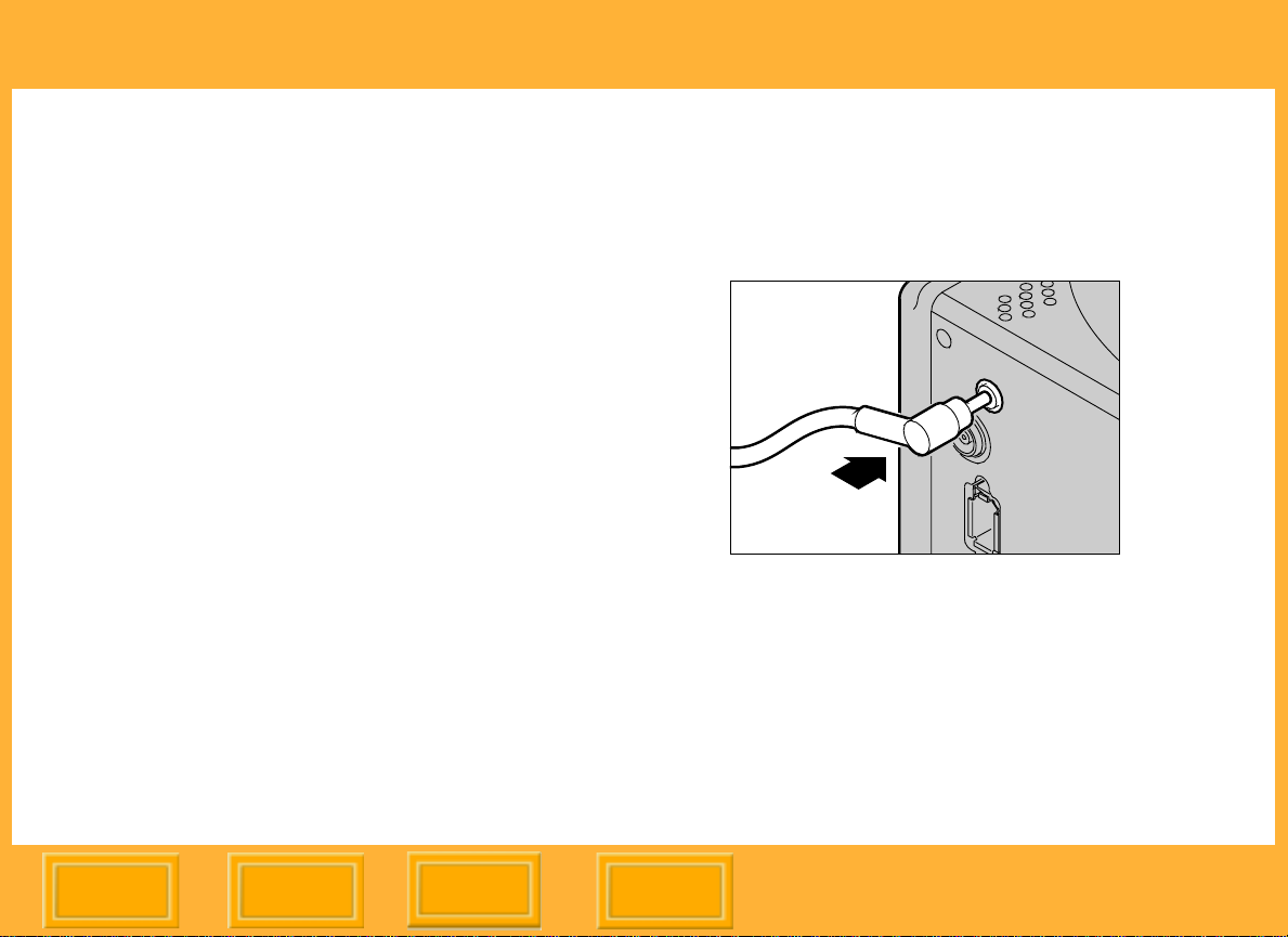
Connecting the Camera Lens
You must connect the included Lens Sync cable
to the camera lens and the DCS Pro Back Plus
so that the DCS Pro Back Plus knows when the
lens shutter opens and closes.
1 Attach the lens to the camera body.
2 Connect one end of the DCS Pro Back Plus
Lens Shutter Sync cord to the PC socket on
the lens.
3 Connect the other end of the cord to the Lens
Sync Cable jack on the DCS Pro Back Plus.
Contents
Back
Next
Index
38
Page 39

The Basics
Connecting Flash/Strobe Units
Only external flash/strobe units can be used with
the DCS Pro Back Plus. There is no built-in flash
or hot shoe.
Connect your studio flash sync cable to the Flash
Sync Cable jack.
Contents
Back
Next
Index
39
Page 40

The Basics
Image Files
Images captured using the DCS Pro Back Plus
are saved in a proprietary format with a .DCR
extension.
You must use the DCS Capture Studio or DCS
Photo Desk software to convert the .DCR files to
a format such as JPEG or TIFF before you can
open, view, or print them using other image
editing or processing applications.
The DCS Capture Studio and DCS Photo Desk
software convert the images as well as provide
image-editing features.
Contents
Back
Next
Index
40
Page 41

The Basics
Storing Images
Images are stored on either a Compact Flash
Card (page 42) inserted in the DCS Pro Back
Plus or on the computer hard drive.
Refer to the DCS Capture Studio, DCS Camera
Manager, or DCS Photo Desk software User’s
Manual or Help for instructions on storing images
on the computer.
Images are stored on an inserted Compact Flash
Card when ANY of the following conditions occur:
! Camera is operating in portable mode
! Camera is connected to a computer but the
computer is not turned on
! Camera is connected to a computer that is
powered but the Capture Studio sof tware is
not running
Images are stored on the computer hard drive
when BOTH of the following conditions occur
! Camera is connected to an appropriately
configured computer
! Capture Studio software is running
Contents
Back
Next
Index
41
Page 42

The Basics
Compact Flash (CF) Cards
The DCS Pro Back Plus has two slots for
Compact Flash+ Type 2 Cards (CF Cards). The
cards can be solid state or IBM MicroDrives.
Card2 slot
Card1 slot
Card door
You can use one or two cards. Only one card is
active at a time, and captured images are saved
on the active card.
The cards are referenced as Card1 and Card2 on
various menus which appear on the Image LCD.
" When the camera is connected to the
computer and the Capture Studio sof tware is
running, images are saved to the computer,
regardless of whether a card is present.
Contents
Back
Next
The front slot (closest to the camera body) holds
Card1, and the rear slot holds Card2.
Index
42
Page 43

The Basics
Inserting a CF Card
1 Open the Card door.
2 Insert a card in a slot and press firmly until you
feel the card seat.
The card can only be inserted in one
orientation.
When using a single card, you can use either
slot.
3 Insert a second card, if needed.
The first card inserted is the active card unless
you select the other card (page 45).
4 Close the Card door.
Contents
Back
Next
Index
43
Page 44

The Basics
Ejecting a CF Card
1 Open the Card door.
CAUTION:
The Card Busy LED flashes when images are
being accessed. Do not remove the card
when the LED is flashing. Doing so could
destroy all image files on the card.
Card2 Busy LED
Card1 Eject button
Card2 slot
Card1 slot
Card door
Card1 Busy LED
Card2 Eject button
2 Press the Eject button next to the card to be
ejected.
Contents
Back
Next
Index
44
Page 45
The Basics
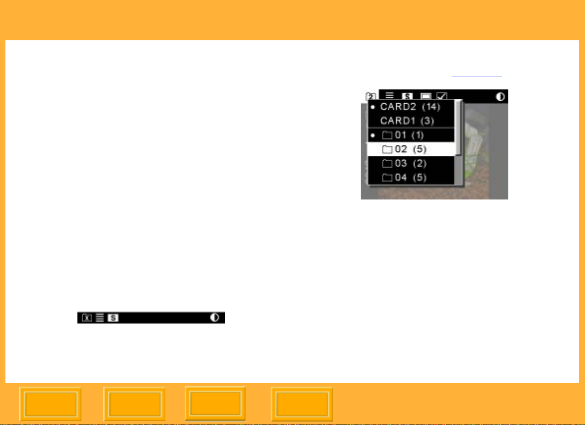
Selecting a CF Card or Folder
This procedure applies only when you are
working in portable mode. When connected to
the computer, images are saved on the
computer. Use the Capture Studio or Camera
Manager software to select folders on the
computer.
With two CF Cards, the first card inserted is
automatically selected. With either one or two
cards, the default folder specified in Properties
(page 52) is selected. You can select a different
card or folder, if needed.
If no card is inserted, an x appears in the Folder
icon on the Menu bar.
1 Highlight the Folder icon (page 24).
2 If two cards are inserted, press the top or
bottom of the Four-way switch until CARD1 or
CARD2 is highlighted, indicating the card to be
made active.
3 Press the OK button.
4 Repeat to select a folder.
The active card and folder are indicated by a •
symbol.
Contents
Back
Next
5 Press the OK button.
Index
45
Page 46

The Basics
Accessing Images on a CF Card
After you capture images to a CF Card, you need
to copy them to a computer with Capture Studio
software.
1 Eject the CF Card (page 44) from the DCS Pro
Back Plus.
2 If your computer has a CF Card reader, insert
the CF Card in the reader. If your computer
uses a PC Card reader, first insert the CF
Card into a PC Card adapter.
3 If the DCS Capture Studio or DCS Photo Desk
software is installed on your computer, you
can access the images directly from the CF
Card or copy them from the card to a folder on
the computer’s hard drive. Otherwise, copy
the image files to a server which can be
accessed by a computer that has DCS
Capture Studio or DCS Photo Desk software
installed.
Contents
Back
Next
Index
46
Page 47

The Basics
Formatting a CF Card
Occasionally you may need to format a CF Card
if it was formatted incorrectly or if the data on the
card becomes corrupted.
There are two ways to format a card:
! Quick format removes the directory
structure but does not erase data. It may be
possible to recover files (page 48) after a
Quick format.
! Full format erases all information and
“cleans up” the card. Images cannot be
recovered.
" Cards are formatted in PC DOS format.
1 If two CF Cards are inserted, remove the card
that you do not plan to format.
" The format operation will not occur when two
cards are inserted, to prevent formatting the
wrong card.
2 Highlight the Menu icon (page 24), and
choose Main Menu from the drop-down menu
(page 25).
3 Choose Card from the Main menu.
4 Choose Quick Format or Full Format from the
Card menu.
5 If you didn’t remove the inactive card in step 1,
remove it now, then press the OK button.
If you removed the active card, re-insert it in
the proper slot, then press the OK button.
6 Press the OK or Cancel button.
Contents
Back
Next
Index
47
Page 48

The Basics
Recovering Data on a CF Card
The Recover Card feature lets you recover files
recently deleted from a CF Card. Files can be
recovered if:
! The card was formatted using a DCS Pro
Back Plus
! The images were captured using a DCS
Pro Back Plus
! The files have not been overwritten
When you recover files, a folder named Recover
is automatically created on the card, and the
recovered files are saved there.
" You cannot capture images to the Recover
folder. If you capture an image while the
Recover folder is selected, the image is
saved in the default folder specified in
Properties (page 52).
1 Highlight the Menu icon (page 24), and
choose Main Menu from the drop-down menu
(page 25).
2 Choose Card from the Main menu.
3 Choose Recover Card from the Card menu.
Images that have not been overwritten are
recovered and saved in the Recover folder.
A Recovering Files screen appears during the
recovery. When complete, another screen
displays the number of files recovered.
4 Press the OK button.
Another screen recommends that you format
the card before capturing more images.
5 Press the OK button.
IMPORTANT:
Do not format until you save all needed images in
another location.
Contents
Back
Next
Index
48
Page 49

Configuring Your Camera
Configuring Your Camera
Setting the Date and Time
A date and time stamp is associated with each
image file.
Inside the DCS Pro Back Plus, a small built-in
rechargeable battery maintains the date and time
when the camera is not receiving power. It is
recharged when the camera is powered, and
maintains the date and time for up to 14 days. If
this battery loses its charge, you need to reset
the date and time.
" You cannot access this battery.
To Set the Date and Time
1 Highlight the Menu icon (page 24) then
choose Main Menu from the dropdown menu
(page 25).
2 Choose Date/Time from the Main menu.
3 Press the left or right side of the Four-way
switch to sequence through the numeric fields.
4 Press the top or bottom of the Four-way switch
to change the highlighted numeric value.
5 Press the OK or Cancel button.
Contents
Back
Next
Index
49
Page 50

Configuring Your Camera
Setting Camera Properties
You can change the following camera properties:
! Delay before Battery Save mode activation
(page 51)
! Delay before the Image LCD display turns
off (page 51)
! Default folder for image capture (page 52)
! Video format (page 53)
! Video signal (page 53)
In addition, you can view the total number of
camera actuations (page 52)
Displaying the Properties Menu
Highlight the Menu icon (page 24) then choose
Properties from the drop-down menu (page 25).
The Properties menu appears.
Contents
Back
Next
Index
50
Page 51

Configuring Your Camera
Setting Battery Save Onset
When the DCS Pro Back Plus is powered by
battery and you don’t touch any controls during
the specified Battery Save Onset time, it enters
Battery Save state. You can change the onset
time (page 63) from 1:00:00 to 23:59:59
(HH:MM:SS).
The default onset time is 60 minutes.
1 Display the Properties menu (page 50).
2 Choose Battery Save Onset from the
Properties menu.
The Battery Save Onset screen appears.
3 Press the left or right side of the Four-way
switch to sequence through the numeric fields.
4 Press the top or bottom of the Four-way switch
to change the highlighted numeric value.
Setting Display Off Time
Extended use of the Image LCD can drain your
battery. For this reason, the LCD turns off after
the length of time specified in the Display Off
Time property.
The default Display Off Time is 60 seconds.
1 Display the Properties menu (page 50).
2 Choose Display Off Time from the Properties
menu.
3 Press the left or right side of the Four-way
switch to sequence through the numeric fields.
4 Press the top or bottom of the Four-way switch
to change the highlighted numeric value.
5 Press the OK or Cancel button.
5 Press the OK or Cancel button.
Contents
Back
Next
Index
51
Page 52

Configuring Your Camera
Total Actuations
You can determine the number of images
captured by the DCS Pro Back Plus from the time
of its manufacture.
1 Display the Properties menu (page 50).
2 Select Total Actuations.
The total number of images captured appears.
Use Folder01
You can change the default folder used when a
CF Card is inserted (page 43).
If you do not change the default folder, the default
is the lowest numbered empty folder.
1 Display the Properties menu (page 50).
2 Select Use FOLDER01.
3 Choose Yes or No.
If you choose Yes, FOLDER01 will be active
when you insert a CF Card.
If you choose No, the lowest numbered empty
folder will be active when you insert a CF
Card.
Contents
Back
Next
Index
52
Page 53

Configuring Your Camera
Video Format
You can specify the format standard used when
you view images on an external monitor
(page 86):
! NTSC - North America (default)
! PAL - Europe and Asia
1 Display the Properties menu (page 50).
2 Select Video Format.
3 Choose NTSC or PAL on the Video Format
screen.
Video Signal
You can specify the video signal standard used
when you view images on an external monitor:
! S-Video (page 86) provides a higher level of
image quality (default - requires an S-Video
cable - not included)
! Composite (requires a special cable - not
included)
1 Display the Properties menu (page 50).
2 Select Video Signal.
3 Select S-Video or Composite on the Video
Signal screen.
Contents
Back
Next
Index
53
Page 54

Before You Begin
Using the Camera Connected to a Computer
Using the Camera Connected to a Computer
Getting Started
To start using your camera connected to a
computer, do the following.
" It is not necessary to turn the computer off.
1 Assemble the camera (page 33).
2 Install the included DCS Capture Studio, DCS
Camera Manager, and DCS Photo Desk
software. (Follow the instructions on the
software CDs.)
3 Connect the camera to the computer and
power supply (page 55).
4 Turn the computer on, if it isn’t already.
" The Power button has no effect when the
camera is connected to a computer .
5 Start the Capture Studio software or Camera
Manager software.
6 Capture images.
7 Review and edit the images, as needed, in the
DCS Capture Studio or DCS Photo Desk
software and save them to the computer’s
hard drive in the desired format.
Contents
Back
Next
Index
54
Page 55

Using the Camera Connected to a Computer
Connecting the Camera to the Computer and Power Supply
Depending on your computer configuration and
your available accessories, choose one of the
following ways to connect the DCS Pro Back
Plus to a computer and a power supply.
! DCS Pro Back Plus and DCS Pro Back
Plus AC adapter connect to a computer
with two IEEE 1394 ports (page 56)
! DCS Pro Back Plus and DCS Pro Back
Plus AC adapter connect to an IEEE 1394
hub which connects to a computer with one
IEEE 1394 port (page 57)
! DCS Pro Back Plus connects to a battery
power source and a computer with one or
more IEEE 1394 ports (page 58)
AC Adapter
A DCS Pro Back Plus 24VDC AC adapter is
included with the DCS Pro Back Plus. Do not use
any other type of AC adapter with your camera.
Contents
Back
Next
Index
55
Page 56

Using the Camera Connected to a Computer
Connecting to a Computer with T wo IEEE 1394 Ports
DCS Pro Back Plus
AC adapter
Computer
IEEE
1394 cable
DC
AC
1 Connect one end of the included 10m IEEE
1394 cable to the IEEE 1394 port on the DCS
Pro Back Plus.
2 Connect the other end of the IEEE 1394 cable
to an IEEE 1394 port on the computer.
3 Connect the cable from the included AC
adapter to a different IEEE 1394 port on the
computer.
4 Plug the AC adapter into a wall socket.
Contents
Back
Next
Index
56
Page 57

Using the Camera Connected to a Computer
Connecting to a Computer with a Single IEEE 1394 Port
In addition to accessories included with the DCS
Pro Back Plus, you need:
! IEEE 1394 hub
! 6-wire IEEE 1394 cable
DCS Pro Back Plus
AC
Computer
IEEE
1394 cable
IEEE
1394 hub
DC
AC adapter
1 Connect one end of the included 10m IEEE
1394 cable to the IEEE 1394 port on the DCS
Pro Back Plus (page 56).
Contents
Back
Next
2 Connect the other end of the IEEE 1394 cable
to any of the ports on the IEEE 1394 hub.
3 Connect the cable from the included AC
adapter to either one of the remaining ports on
the IEEE 1394 hub.
4 Connect another 6-wire IEEE 1394 cable (not
included) from another port on the IEEE 1394
hub to the single IEEE 1394 port on the
computer.
5 Plug the AC adapter into a wall socket.
Index
57
Page 58

Using the Camera Connected to a Computer
Connecting to a Computer and Using Battery Power
IEEE 1394 cable
Battery
Computer
Battery cable
1 Connect one end of the included 10m IEEE
1394 cable to the IEEE 1394 port on the DCS
Pro Back Plus.
DCS Pro Back Plus
2 Connect the other end of the IEEE 1394 cable
to an IEEE 1394 port on the computer.
3 Following the instructions included with your
battery pack, connect the battery pack and its
cable.
4 Insert the cable into the Battery Connection
jack on the DCS Pro Back Plus.
5 Turn on the battery pack’s power switch.
Contents
Back
Next
Index
58
Page 59

Using the Camera Connected to a Computer
Powering Your Camera
When connected to the computer, your camera
receives its power from the included AC adapter
(via the IEEE 1394 interface) or a compatible
battery. If you use an IEEE 1394 cable other than
the one included with your DCS Pro Back Plus,
ensure that it is a 6-wire IEEE 1394 cable (4-wire
cables will not work).
If you do not use the AC adapter with the IEEE
1394 cable, the DCS Pro Back Plus will not
receive enough power. An error message
appears.
To Power the Camera
With the IEEE 1394 cable and DCS Pro Back
Plus AC Adapter (page 55) or a compatible
battery (page 61) connected, turn the computer
on.
It takes 5-6 seconds for the DCS Pro Back Plus
to activate once the initial power signal is
received. When ready, the Camera Ready LED
illuminates. (The Power button has no effect
when power is supplied by the IEEE 1394
connection.)
" If you turn the Image LCD on, it turns off
automatically after the time specified in the
Display Off Ti me property (page 51).
To Turn the DCS Pro Back Plus Off
Disconnect the IEEE 1394 cable.
Contents
Back
Next
Index
59
Page 60

Using the Camera in Portable Mode
Using the Camera in Portable Mode
Getting Started
To start using your camera in portable mode (not
connected to a computer), do the following:
1 Assemble the camera (page 33).
2 Connect a power supply (page 61).
3 Insert one or two CF Cards (page 42).
4 Turn the camera on (page 62).
5 Capture images.
6 Review the images (page 68) on the Image
Display LCD (or enable the video output
(page 86) to view them on a monitor.)
7 Remove the CF Cards from the camera and
insert them in a card reader.
8 Copy the image files to the computer.
If images are copied to a computer (page 12)
running DCS Capture Studio or DCS Photo
Desk software, you can access them using the
software.
Alternatively, you can copy them to a server
accessible from a computer running the DCS
Capture Studio or DCS Photo Desk software.
9 Edit the images, as needed, in the DCS
Capture Studio or DCS Photo Desk software
and save them in the desired format.
Contents
Back
Next
Index
60
Page 61

Using the Camera in Portable Mode
Connecting to a Power Supply
When you are working in portable mode, your
camera may receive its power from either a
compatible third party battery or the included
DCS Pro Back Plus AC adapter (page 55).
Connecting to a Compatible Third Party Battery
In addition to included accessories, you need:
! Compatible battery
! Battery cable
1 Following the instructions you received with
your battery, connect its cable to the battery
pack.
2 Insert the cable into the Battery Connection
port on the DCS Pro Back Plus.
Contents
Back
Next
Index
61
Page 62

Using the Camera in Portable Mode
Connecting to the AC Adapter
1 Connect the cable from the included AC
adapter (page 55) to the IEEE 1394 port on
the DCS Pro Back Plus.
2 Plug the AC adapter into a wall socket.
Turning the Camera On and Off
Press the Power button to turn the camera on or
off.
PWR
DCS Pro Back Plus
" The button is only effective when the camera
is powered by battery . When powered by AC
adapter, the camera is always on.
The Camera Ready LED illuminates when the
power is on.
" If you turn the camera off while the DCS Pro
Back Plus is busy, the Camera Ready LED
flashes until the task completes.
CANCEL
MENU
OK
Contents
Back
Next
Index
62
Page 63

Using the Camera in Portable Mode
Conserving Batteries
To extend the life of the battery pack, keep the
following in mind:
! Follow the instructions you received with
your compatible third party battery for its
care and use.
! Older batteries may not last as long as
newer batteries.
! Minimize use of the Image LCD and turn it
off when not in use.
" You may be able to obtain information about
the battery’s charge level from lights on the
battery pack. This information is not provided
on the DCS Pro Back Plus.
Battery Save State
To conserve the battery’s charge, the DCS Pro
Back Plus enters Battery Save state if no DCS
Pro Back Plus controls are touched for a
specified period of time. When this happens, the
Camera Ready LED is extinguished, and the
Image LCD and DCS Pro Back Plus buttons
become inactive.
The default onset of Battery Save state is 60
minutes. Y ou can change the Battery Save Onset
time in Properties (page 51).
To Exit Battery Save State
Press the Power button.
The DCS Pro Back Plus turns on with the same
settings it had before Battery Save state began.
Contents
Back
Next
Index
63
Page 64

Capturing Images
Capturing Images
Overview
This section describes operations specific to the
DCS Pro Back Plus.
Refer to the User’s Manual for your
HASSELBLAD 555ELD, 553ELX, 503CXi, or
503CW, or MAMIYA RZ67 PRO II camera body
for additional instructions on image capture.
Refer also to the list of unsupported features
(page 84) for the HASSELBLAD or MAMIYA
camera when used with the DCS Pro Back Plus.
Contents
Back
Next
Index
64
Page 65

Before You Begin
Capturing Images
Formatting Images
The DCS Pro Back Plus has a square imager
that captures images with a square format. You
can change this format, if needed.
The new format is applied to subsequently
captured images.
The Focus Screen overlay indicates the
approximate area of coverage for each format.
5x5
Full Frame (4x4)
Horizontal format
5x4
indicators (4x3)
4x5
5x5
Full Frame (4x4)
To Format Images
1 Highlight the Menu icon (page 24), and
choose Main Menu from the drop-down menu
(page 25).
2 Choose Image Format from the Main menu.
3 Choose the desired option from the Image
Format menu (Full Frame, 4x5, or 5x4):
The current format is indicated on the Status
screen (page 27).
F - Full frame image (5x5)
H - Horizontal format (5x4)
V - Vertical format (4x5)
Contents
Back
Next
Index
65
Page 66

Capturing Images
Intervalometer
Your camera has an Intervalometer that
automatically captures a sequence of images at
specified intervals over a specified time period.
You might use the Intervalometer to capture a
flower bud opening or for unattended
surveillance.
The Intervalometer is disabled automatically after
the specified time has elapsed, even if the
specified number of images have not been
captured. For example, if you set the
Intervalometer for fifteen exposures at one
second intervals, the buffer would fill after a few
exposures, and the camera would not be able to
maintain the one second interval. It would stop
capturing images after fifteen seconds even
though fifteen images had not been captured.
" While the Intervalometer is enabled, the
camera does not enter Battery Save state.
1 Highlight the Menu icon (page 24), and
choose Main Menu from the drop-down menu
(page 25).
2 Choose Intervalometer from the Main menu.
3 Choose the desired option from the
Intervalometer menu.
4 Change settings, as needed, on the
Intervalometer options screens (page 67).
5 Press the left or right side of the Four-way
switch to sequence through the numeric fields.
Press the top or bottom of the Four-way switch
to change the highlighted numeric value.
Press the OK or Cancel button. (In the Enable
screen, choose Yes or No.)
Contents
Back
Next
Index
66
Page 67

Capturing Images
Intervalometer Options
Frame Count Interval Delay Enable
Screen:
Description: Specifies the
number of frames
to capture
Specifies the
interval between
image captures
Specifies the delay
before onset of the
Intervalometer
function
Range: 1-9999 frames 3 seconds to
23:59:59
(HH:MM:SS)
1 second to
23:59:59
(HH:MM:SS)
Default: 10 frames 10 seconds 1 second
Contents
Back
Next
Index
Yes enables the
Intervalometer with
the values
displayed in the
Intervalometer
screen
No disables the
Intervalometer
67
Page 68

Using the Image LCD
Using the Image LCD
Reviewing Images
You can review images on the active CF Card
(page 42) in one of five Display modes:
! Single Image mode
! Zoom mode
! Histogram mode
! Multiple Image mode
! Delete mode
" The Location bar (page 73) appears at the
bottom of the screen in Single Image or
Multiple Image Display mode.
Selecting a Display Mode
1 Press the OK button to turn the Image LCD on
or, if a menu is displayed, press the Cancel or
Menu button to return to Display mode.
2 Press the top or bottom of the Four-way switch
to change the Display mode.
A pop-up display containing icons for each
Display mode appears briefly, with the active
icon highlighted.
Single
Zoom
Histogram
Multiple
Delete
Contents
Back
Next
Index
68
Page 69

Before You Begin
Using the Image LCD
Single Image Display Mode
The thumbnail for the current image appears with
the Status bar (page 73) at the left.
Zoom Display Mode
The thumbnail for the current image appears with
a Region of Interest box and crosshairs (page
70). The Region of Interest box includes the area
of the image that appears when you zoom in.
Enabling or Disabling the Region of Interest Box
Press the OK button to enable the Region of
Interest box.
You can pan or zoom when the Region of
Interest box is enabled.
Press the Cancel button to disable the Region of
Interest box.
You can navigate to a different image when
the Region of Interest box is disabled.
Contents
Back
Next
Index
69
Page 70

Using the Image LCD
Zooming
With the Region of Interest box enabled
(page 69) press the OK button.
The first actuation zooms to 1:4 (one pixel
displayed for every four), the second to 1:1, and
the third returns to the un-zoomed 1:16.
" When zoomed in to 1:1, the crosshairs
appear but the Region of Interest box does
not. You can still pan, however.
Panning
With the Region of Interest box enabled, press
the appropriate part of the Four-way switch to
move the Region of Interest box around.
If the edge of the thumbnail is reached, the image
moves in the opposite direction.
Navigating Through Images in Zoom Mode
Press the Cancel button to turn the Region of
Interest box off and navigate (page 74) to other
images.
Luminometer Crosshairs
The crosshairs, which appear when the Region
of Interest box is on, indicate the level of
luminance channel saturation of pixels below the
center of the crosshairs. This level is indicated in
stops (-3 to 3.25) and percentages (2 to 180%).
Contents
Back
Next
Index
70
Page 71

Using the Image LCD
Histogram Display Mode
When Histogram mode is active, the following
information appears for the active image:
! Active folder number/name
! Image number
! Date and time of image capture
! Image thumbnail
! Histogram for the image
Multiple Image Display Mode
Four image thumbnails appear with the Status
bar (page 73) at the left. The current image is
highlighted.
" Thumbnails may appear with varying image
formats (page 65) as each thumbnail is
displayed in its selected image format.
Contents
Back
Next
Index
71
Page 72

Using the Image LCD
Image Delete Display Mode
Use Image Delete Display mode to delete the
current image. You can also delete groups of
images (page 75) using a Main menu option.
" If you delete an image by mistake, you can
get it back if you immediately perform the
Recover function (page 48).
One image thumbnail (for the current image)
appears with instructions for deleting it.
To Delete a Single Image
1 Press the OK button to delete the displayed
image.
2 Press the OK or Cancel button in response to
the confirmation screen. (The Cancel button
dismisses the screen without deleting the
image.)
A feedback screen appears for two seconds or
until you manipulate a button on the DCS Pro
Back Plus.
Contents
Back
Next
Index
72
Page 73

Using the Image LCD
Status Bar
When image thumbnails are displayed in Single
Image or Multiple Image Display mode (page 68),
a Status bar appears at the left of the display. It
contains some or all of the following information.
Card # (if 2 cards)
Folder #
Tag - if image
tagged (page 77)
Image number
Location Bar
A Location bar appears at the bottom of the
Image LCD when you are navigating through
images in Single Image or Multiple Image Display
mode (page 68). It indicates the position of the
current image relative to the other images in the
active folder.
Contents
Back
Next
Index
73
Page 74

Using the Image LCD
Navigating through Displayed Images
Press the left or right side of the Four-way switch
to navigate through images in the selected folder.
" This works in all Display modes except Zoom
mode (page 69) when the Region of Interest
box is enabled.
The right side navigates “forward” to highernumbered images in the folder, and the left side
navigates “backward.”
If you continue navigating forward after the last
image is reached, the navigation wraps around to
the first image. If you continue navigating
backward after the first image is reached, the
navigation wraps around to the last image.
To indicate the first or last image in the folder , a
blank screen appears after the last or first image.
Selecting an Image
As you navigate through the images in Multiple
Image Display , the images are highlighted one at
a time. Release the Four-way switch when the
desired image is highlighted.
In the other Display modes, release the Four-way
switch when the desired image appears.
Contents
Back
Next
Index
74
Page 75

Using the Image LCD
Deleting Groups of Images
You can delete groups of images using a Main
menu option. You can also delete single images
using Image Delete Display mode (page 72).
To Delete Groups of Images
1 Highlight the Menu icon (page 24), and
choose Main Menu from the dropdown menu
(page 25).
2 Choose Delete Images from the Main menu.
3 Choose the desired option from the Delete
Images menu.
4 When prompted, Press the OK or Cancel
button.
If you Press the OK button, a progress screen
appears. If you press the Cancel button while
the deletion is in progress, images that have
not yet been deleted remain on the card.
A final screen appears informing you of the
number of images deleted.
5 Press the OK button.
Contents
Back
Next
Index
75
Page 76

Using the Image LCD
Display Contrast
You can change the contrast and lighten or
darken the images displayed on the Image LCD
panel.
" Changing contrast does not affect the stored
images, only the view of the images on the
Image LCD.
1 Highlight the Contrast icon (page 24).
2 Press the top or bottom of the Four-way switch
to move the slider bar up to lighten, or down to
darken the displayed image.
Overexposure Indicator
You can highlight areas of overexposure in
Single or Multiple Image Display modes.
1 Choose Single or Multiple Image mode
(page 68).
2 Highlight the Menu icon (page 24), and
choose Main Menu from the drop-down menu
(page 25).
3 Choose Overexposure Indicator from the Main
menu.
A check mark appears when highlighting is on.
4 Press the OK button to toggle highlighting on
or off.
Contents
Back
Next
Index
76
Page 77

Using the Image LCD
Tagging Images
You can tag one or more images then perform
operations on the tagged (or untagged) images.
1 Select any Display mode except Delete mode
(page 68).
2 Select the image to be tagged (page 74).
3 Highlight the Tag icon in the Menu bar.
A check mark appears in the Status bar.
To untag a tagged image, highlight the Tag
icon when a tagged image is selected.
Contents
Back
Next
Index
77
Page 78

Caring for Your DCS Pro Back Plus
Caring for Your DCS Pro Back Plus
Cleaning
Clean the camera body as described in the
HASSELBLAD or MAMIYA User’s Manual.
Cleaning the DCS Pro Back Plus
1 Turn the DCS Pro Back Plus off or disconnect
the DCS Pro Back Plus from the computer.
2 Using a lint-free cloth with light pressure, clean
only the outside enclosures and the Image
LCD panel.
IMPORTANT:
Do not use liquid cleaners or aerosol cleaners on
the outside of the DCS Pro Back Plus.
Before connecting the DCS Pro Back Plus to the
camera body, clean the slots at the bottom of the
DCS Pro Back Plus and the locating posts on the
camera body using isopropyl alcohol on a lintfree lens cleaning tissue.
Cleaning the IR or Anti-aliasing Filter
1 Remove the filter from the DCS Pro Back Plus
(page 21).
2 Gently blow off the dust using commercially
available canned air (low pressure). If the filter
is still dirty, contact your dealer or service
representative.
3 If the imager is dirty, check the KODAK Web
site (www.kodak.com) for instructions on
cleaning. Choose Service and Support, then
under Professional Photography choose
Cameras, Digital and choose DCS Pro Back
Plus. Follow the instructions under Cleaning
Recommendations for CCD Coverglass.
Contents
Back
Next
Index
78
Page 79

Before You Begin
Caring for Your DCS Pro Back Plus
Storing
These storage tips apply to the DCS Pro Back
Plus. Store the camera body as described in the
HASSELBLAD or MAMIYA User’s Manual.
! If you have an IR or anti-aliasing filter not in
use, store it in the pocket on the included
body cap.
! Wrap in a clean, soft cloth and place in a
well-ventilated, cool, dry, dust-free place.
! Keep out of direct sunlight and away from
“hot spots” such as the trunk of a car.
! Avoid places where chemical agents such
as moth balls are used.
! In extreme humidity, use a desiccant.
! If the DCS Pro Back Plus has been stored
for a long period of time, carefully check the
operation or have it thoroughly tested at an
authorized service center.
" After storing the DCS Pro Back Plus for
several days, you may need to set the date
and time (page 49).
Contents
Back
Next
Index
79
Page 80

Caring for Your DCS Pro Back Plus
!
When the DCS Pro Back Plus is removed
from the camera body , att ach the body cap.
Place the top of the body cap at an angle so
that it catches the Release button, then
press the bottom of the body cap in place.
Contents
Back
Next
Index
80
Page 81

Caring for Your DCS Pro Back Plus
Firmware
Firmware is the software program that runs within
the DCS Pro Back Plus and controls its
operation. If a new firmware version becomes
available, you can download it from the KODAK
Web site (www.kodak.com/go/proback) and
update the firmware within the DCS Pro Back
Plus (page 82).
3 Choose Version from the Firmware menu.
Checking the Current Firmware Version
You can check the firmware version currently
running on your DCS Pro Back Plus.
1 Highlight the Menu icon (page 24), and
choose Main Menu from the drop-down menu
(page 25).
2 Choose Firmware from the Main menu.
Contents
Back
Next
The firmware version appears.
4 Press the OK button.
Index
81
Page 82

Caring for Your DCS Pro Back Plus
Updating Firmware
1 On a computer with Internet access, g o to
www.kodak.com, then choose Service and
Support. Choose Cameras, Digital from the
Professional Photography list, choose DCS
Pro Back Plus, then choose Firmware and
Host Software.
2 Download the firmware to your computer.
3 Insert a CF Card into the card reader attached
to your computer.
4 On the computer, copy the firmware file to the
card’s root directory.
IMPORTANT:
The firmware can be updated only from the
card’s root directory.
5 Insert the CF Card (page 43) in the DCS Pro
Back Plus.
6 Highlight the Menu icon (page 24), and
choose Main Menu from the drop-down menu
(page 25).
7 Choose Firmware from the Main menu.
8 Choose Update from Card from the Firmware
menu.
A confirmation screen appears.
9 Press the OK or Cancel button.
If you press OK, approximately fifteen seconds
pass. A progress screen appears while the
firmware is updating.
" The camera automatically restarts after the
firmware is updated.
Contents
Back
Next
Index
82
Page 83

Specifications
Specifications
Type Digital camera back which attaches to existing medium format
camera bodies having removable film magazines
Imager size 16 million pixels (4080 x 4080)
Image LCD 2-inch diagonal LCD provides image thumbnail, adjustable contrast,
and status of digital features
IEEE 1394 interface and
power source
Power source in portable
mode
AC adapter 24VDC
Weight Approximately 3.5 pounds (with two CF Cards and lens sync cable)
Dimensions 90 mm x 90 mm x 100 mm
Burst rate 1 image every 2 seconds
Burst depth 6 (possibly more, depending on scene content)
DRAM on-board 128 MB
ISO 100
S-Video NTSC or PAL
Used to connect power from the AC Adapter to the DCS Pro Back
Plus and to transfer images from the DCS Pro Back Plus to a
computer running Capture Studio or Camera Manager software
• DIGITAL CAMERA BATTERY with cable DCS-9.6V—see
www.digitalcamerabattery.com
• QUANTUM Battery 2 with cable MDC3—see www.qtm.com
• Other compatible third party battery and cable
Contents
Back
Next
Index
83
Page 84

Unsupported Features
Unsupported Features
Unsupported or Partially Supported Features (HASSELBLAD Cameras)
Most camera body features are supported when
the DCS Pro Back Plus is attached. (Refer to the
HASSELBLAD instruction manual.) Exceptions
are listed below.
Unsupported Camera Body Features
! When using HASSELBLAD lenses of the
C/CB/CR/CFi and CFE series with the DCS
Pro Back Plus, shutter speeds greater than
1/4 second are not supported.
! The Mode Selector dial must only be used
in the O (Normal mode) or A (Automatic
mode) positions. When a DCS Pro Back
Plus is installed on a HASSELBLAD
555ELD or 553ELX, the O and A modes are
essentially the same.
! Infrared photography is not supported.
! Trigger release commands sent to the
remote control socket on the 555ELD
autowinder are not supported.
! Multiple exposures are not supported.
! ISO settings other than 100 are not
supported.
! The Automatic setting of the 555ELD and
553ELX Mode Selector dial has a frame
rate of about 1 frame/second. The DCS Pro
Back Plus does not support this frame rate.
Accessories
The DCS Pro Back Plus supports most
accessories used by the HASSELBLAD 555ELD.
Exceptions are listed below:
! HASSELBLAD Prism Viewfinder PM90
! Meter Prism Viewfinder PME90
Contents
Back
Next
Index
84
Page 85

Before You Begin
Unsupported Features
Unsupported or Partially Supported Features (MAMIYA RZ67 PRO II)
Most camera body features are supported when
the DCS Pro Back Plus is attached. (Refer to the
RZ67 PRO II Instruction Manual by MAMIYA.)
Exceptions are listed below.
Unsupported Camera Body Features
! With the DCS Pro Back Plus attached,
shutter speeds greater than 1/4 second are
not supported.
! With the DCS Pro Back Plus attached, the
R-M lever must be set to the multiple
exposure (M) position.
! Infrared photography is not supported.
! With the DCS Pro Back Plus attached, only
a single ISO can be used.
! Multiple exposures are not supported.
Contents
Back
Next
Index
85
Page 86

Using an S-V i deo Monitor
Using an S-Video Monitor
You can preview images on an external S-Video
monitor. This provides a larger version of the
image displayed on the Image LCD.
" When the external monitor is enabled, the
Image LCD turns off.
When you capture an image, it automatically
appears on the connected S-Video monitor. You
can preview it and make necessary camera
adjustments. When you capture another image,
the new one appears.
Connecting
Connect an S-Video cable (not included) to the
S-Video Output port.
Contents
Back
Next
Index
86
Page 87

Using an S-V i deo Monitor
Enabling
1 Highlight the Menu icon (page 24) then
choose Main Menu from the drop-down menu
(page 25).
2 Choose External Video from the Main menu.
3 Choose On from the External Video screen.
A Video icon appears on the Menu bar.
4 Highlight the Video icon.
5 Press the OK button.
The current image appears on the external
monitor and the Image LCD turns off.
Disabling
Press the OK, Cancel, or Menu button (page 28)
to disable the external monitor and turn the
Image LCD on.
Navigating Through Images
Press the left or right side of the Four-way switch
to navigate through images in the selected folder.
" This works only in Single Image Display
mode (page 69).
Contents
Back
Next
Index
87
Page 88

Warnings and Cautions
Warnings and Cautions
! To prevent fire or shock hazard, use only the
recommended accessories and attachments.
! Use only the power source type indicated on
the name plate of the AC adapter. A line
voltage outside this range can destroy the AC
adapter and/or the DCS Pro Back Plus.
! Do not substitute other types of cables for
supplied cables or cables listed in the System
Requirements section (page 12).
! Do not remove a CF Card from the camera,
disconnect or turn off a battery supply, or
disable the AC adapter while the Card Busy
LED inside the Card door is blinking. The
blinking indicates that data is being read from
or written to the card. Y ou may lose dat a if you
remove a card at this time.
! Use extreme care when handling CF Cards as
they are easily damaged. If dropped, the CF
Card may be destroyed, resulting in the loss of
all data.
! Do not use the DCS Pro Back Plus where it
can come in contact with water. It is not
waterproof or splash-resistant.
! Handle the DCS Pro Back Plus with care.
Treat the anti-aliasing filter with the greatest of
care. It is a very expensive device.
! Retain the safety and operating instructions for
future reference. Retain the packing case for
use if your camera needs to be shipped.
! Treat the imager with extreme care. It is very
expensive to replace.
! The anti-aliasing or IR filter is exposed when
the cap is removed. Do not touch or strike this
filter or set it down on a surface.
Contents
Back
Next
Index
88
Page 89

Glossary
Glossary
Aliasing
Compact Flash Card
Artifacts that appear on an image but were not
in the original scene
Anti-aliasing filter
Helps to reduce aliasing at certain focal
distances
Camera Manager
Included software application used to capture
images, copy and transfer images, and set
properties for the DCS Pro Back Plus
Capture Studio software
Included software application used to capture
and process images from the DCS Pro Back
Plus (Macintosh only)
(CF Card) A small, removable device with
PCMCIA-ATA functionality which stores
images captured by the DCS Pro Back Plus
.DCR files
Image files created by the DCS Pro Back Plus
which can only be opened using the included
DCS Capture Studio or DCS Photo Desk
software
Focus screen overlay
Included overlays that fit over the viewfinder to
indicate the scene content that is actually
captured using the DCS Pro Back Plus
Contents
Back
Next
Index
89
Page 90

Glossary
IEEE 1394 interface
High-speed serial interface that transfers
image files from the DCS Pro Back Plus to the
computer, provides power (using the included
AC adapter) to the DCS Pro Back Plus, and
allows the DCS Pro Back Plus to
communicate with the Capture Studio and
Camera Manager software
Image format
In the DCS Pro Back Plus, image format
refers to cropping of images as they are
captured. Choices are: 5x5, 4x5, and 5x4
Image LCD
A two-inch diagonal LCD where you can view
images and change settings on the DCS Pro
Back Plus
Intervalometer
Automatically captures a sequence of images
at specified intervals over a specified period of
time
IR filter
Maintains proper focus, filters out infrared
light, and helps protect the imager’s
coverglass
IEEE 1394 hub
An IEEE 1394 accessory that lets you connect
a number of IEEE 1394 peripherals to a
computer . To be compatible with the DCS Pro
Back Plus, use a hub which conforms to the
IEEE 1394 standard (hot pluggable, can send
and receive data at 00/200/400MBps) and has
at least three ports
Contents
Back
Next
Index
90
Page 91

Glossary
ISO
International Standards Organization settings
regarding the properties of photographic
speed
Luminometer
Measures the levels of luminance channel
saturation in pixels at the center of the
crosshairs in zoom box
Photo Desk
Included software application used to review
and process images from the DCS Pro Back
Plus
Portable mode
Using the camera without connections to the
computer
S-Video
A video interface standard that enables you to
view a camera image on an external monitor
Contents
Back
Next
Index
91
Page 92

Glossary
Tethered
Connected to a host computer with an
approved IEEE1394 cable
Contents
Back
Next
Index
92
Page 93

Warranty
Warranty
CAREFULLY READ THE FOLLOWING WARRANTY TERMS AND CONDITIONS BEFORE USING
YOUR CAMERA. USE OF YOUR CAMERA INDICATES YOUR ACCEPTANCE OF THESE TERMS
AND CONDITIONS. IF YOU DO NOT AGREE WITH THEM, PROMPTLY RETURN THE CAMERA,
UNUSED, ALONG WITH THE ACCOMPANYING MATERIALS, IN THE ORIGINAL PACKAGING.
WARRANTY
KODAK PROFESSIONAL DCS Pro Back Plus
THIS WARRANTY APPLIES ONLY TO EQUIPMENT PURCHASED IN THE UNITED STATES.
Kodak warrants your KODAK PROFESSIONAL DCS Pro Back Plus internal electronics and mechanical
assemblies to be free from defects in material and workmanship for 1 year from the day of purchase.
Kodak warrants the Imager to be free from defects in material and workmanship for 4 years from the date
of purchase. Kodak warrants the Infrared Blocking Filter (IR Filter) to be free from defects in material and
workmanship for 30 days from the date of purchase.
Contents
Back
Next
Index
93
Page 94

Warranty
Warranty Repair Coverage
If this equipment does not function properly during the warranty period due to defects in material or
workmanship, Kodak will, at its option, either repair or replace the equipment without charge, subject to
the conditions and limitations stated herein. Such repair service will include all labor as well as any
necessary adjustments and/or replacement parts.
If replacement parts are used in making repairs, these parts may be remanufactured, or may contain
remanufactured materials. If it is necessary to replace the entire system, Kodak may replace with a
remanufactured system. Repair or replacement carries a 30-day warranty effective at the time of service
problem resolution. This warranty will not extend the original warranty period, and, in the case of parts
replacement, will only apply to parts and labor performed to repair the equipment.
Limitations
REPAIR OR REPLACEMENT WITHOUT CHARGE IS KODAK’S ONLY OBLIGATION UNDER THIS
WARRANTY.
Warranty service will not be provided without dated proof of purchase. Please return the Warranty
Registration card within 30 days of purchase.
As a condition of warranty service, before sending in your equipment to a Kodak authorized service
center for repair, you must first contact a Kodak representative for return authorization and instructions.
Contents
Back
Next
Index
94
Page 95

Warranty
Should you need to return equipment to Kodak, Kodak is not responsible for the loss or damage of
equipment while in transport to a Kodak authorized service center. You may, at your option, choose to
insure equipment for loss or damage with the carrier of your choice.
This warranty becomes null and void if, during shipment, you fail to pack your KODAK PROFESSIONAL
DCS Pro Back Plus in a manner consistent with the repacking instructions.
This warranty does not cover the following:
! Scratches on Imager Cover Glass or IR Filter
! Cracked or damaged Imager Cover Glass or IR Filter
! Circumstances beyond Kodak’s control
! Service or parts to correct problems resulting from the use of attachments, accessories or
alterations not marketed by Kodak
! Unauthorized modifications or service
! Misuse
! Abuse
! Failure to follow Kodak’s operating, maintenance, or repacking instructions
! Failure to use Kodak-supplied items (such as cables).
Contents
Back
Next
Index
95
Page 96

Warranty
KODAK MAKES NO OTHER WARRANTIES, EXPRESS OR IMPLIED, AND SPECIFICALLY
DISCLAIMS THE IMPLIED WARRANTIES OF MERCHANTABILITY AND FITNESS FOR A
PARTICULAR PURPOSE.
KODAK WILL NOT BE RESPONSIBLE FOR ANY CONSEQUENTIAL OR INCIDENTAL DAMAGES
RESULTING FROM THE PURCHASE, USE, OR IMPROPER FUNCTIONING OF THIS EQUIPMENT
EVEN IF THE LOSS OR DAMAGE IS CAUSED BY THE NEGLIGENCE OR OTHER FAULT OF
KODAK. SUCH DAMAGES FOR WHICH KODAK WILL NOT BE RESPONSIBLE INCLUDE, BUT ARE
NOT LIMITED TO, LOSS OF REVENUE OR PROFIT, DOWNTIME COSTS, LOSS OF USE OF YOUR
CAMERA, COST OF ANY SUBSTITUTE EQUIPMENT, FACILITIES, OR SERVICES, OR CLAIMS OF
YOUR CUSTOMERS FOR SUCH DAMAGES.
Outside the United States
In countries other than the United States, warranty terms may be different. Unless a specific Kodak
warranty is communicated to the purchaser in writing by Kodak, no warranty or liability exists even though
defect, damage or loss may be by negligence or other act of Kodak.
Contents
Back
Next
Index
96
Page 97

Warranty
How to obtain service
See your authorized Kodak dealer.
If service is required, your Kodak dealer will instruct you to return the unit to the nearest service center for
repair and will issue a return authorization number.
When returning a KODAK PROFESSIONAL DCS Pro Back Plus for repair, you should pack the unit in its
original packing materials according to the repacking instructions located on the shipping container.
Packing will be the purchaser’s responsibility if the original packing has been discarded or is not available.
Return of the repaired or replaced equipment to the customer can be expected five to seven business
days from the date the equipment is received by the service center.
Product Support Options
During the warranty period for the KODAK PROFESSIONAL DCS Pro Back Plus, you are entitled to
product support for both hardware and software, provided your camera is registered with Eastman Kodak
Company. You may register with Kodak via mail, fax, or through Kodak’s World Wide Web site: http://
www.kodak.com.
Support is provided through a variety of options:
Contents
Back
Next
Index
97
Page 98

Warranty
1 Technical Support through the Web site: http://www.kodak.com.
Support includes F AQs (Frequently Asked Questions), downloadable software updates, and technical
topic articles for reading and downloading.
2 FaxBack Documents on a variety of subjects. In North America the FaxBack system is available at the
following phone number: 1-800-508-1531.
3 Authorized Dealers:
Contact your authorized KODAK PROFESSIONAL dealer for help with operation and connection to
your computer . Your dealer can also provide training for your DCS Pro Back Plus application software.
Authorized dealers can also provide help in purchasing a service maintenance agreement.
4 Telephone Support:
Telephone support is provided without charge during your warranty period only by calling your
authorized dealer. Your camera must be registered with Eastman Kodak Company. Fill out and return
to Eastman Kodak Company the warranty registration card included with your camera. Failure to
register your camera will cause delays in requesting repair of your camera during the warranty period.
5 Out-of-Warranty Support Options
There will be a charge for out-of-warranty call incidents if you wish to speak to a Kodak support
representative. A call incident is defined to include only those issues raised during the first telephone or
e-mail contact. Follow-up telephone calls by Kodak’s representative, and callbacks to Kodak’s Support
Center to resolve the call incident will not be charged as long as charges for any valid, active call
Contents
Back
Next
Index
98
Page 99

Warranty
number are provided. Calls to report bugs or anomalies will be cancelled. Calls to arrange for service
will be cancelled or applied as a credit against the repair estimate or invoice.
Service maintenance agreements, which cover the repair and support of the DCS Pro Back Plus and
software are available. In North America, contact the regional Service Marketing group at: 1-800645-6325
No-charge options include:
! KODAK PROFESSIONAL World Wide Web site: http://www.kodak.com/go/support
! FaxBack Documents
! Your Kodak Professional dealer
Contents
Back
Next
Index
99
Page 100

Index
A
Accessing images on a CF Card 46
Activate button 28
Actuations 52
Anti-aliasing filter 20
Assembling the camera 33
B
Batteries, Conserving 63
Battery connection jack 31
Battery Save onset 51
Battery Save state 63
Buttons 28
Activate 28
Cancel 28
Four-way switch 28
Menu 28
Power 30
C
Camera
Assembling 33
Firmware. See Firmware 81
Turning on and off 62
Camera properties. See Properties 50
Cancel button 28
CF Cards 42
Cleaning 78
Compact Flash Cards 42
Accessing images on 46
Ejecting 44
Formatting 47
Inserting 43
Selecting 45
Computer, Connecting to 55
Connecting
Camera lens to DCS Pro Back Plus 38
Camera to the computer and power
supply 55
Battery power 58
Single IEEE 1394 port 57
Contents
Back
Next
Index
Index-1
 Loading...