


 Loading...
KitchenAid KUIX535HPA00, KUIX535HPS00, KUIX535HBS00, KUIX335HWH00, KUIX335HPS00 Installation Guide
...ICE MAKER INSTALLATION INSTRUCTIONS
INSTRUCTIONS D’INSTALLATION DE LA MACHINE À GLAÇONS INSTRUCCIONES DE INSTALACIÓN DE LA FÁBRICA DE HIELO
CONTENTS / TABLE DES MATIÈRES / ÍNDICE
ICE MAKER SAFETY.................................. |
1 |
INSTALLATION INSTRUCTIONS............... |
2 |
Unpack the Ice Maker.............................. |
2 |
Vacation or Extended |
|
Time Without Use..................................... |
2 |
Location Requirements............................. |
2 |
Electrical Requirements............................ |
3 |
Water Supply Requirements..................... |
4 |
Drain Connection Requirements.............. |
4 |
Door Reversal........................................... |
5 |
Drain Pump Installation |
|
(on some models)..................................... |
8 |
Connect Water Supply............................ |
11 |
Leveling and Securing............................ |
12 |
Custom Wood Panel............................... |
14 |
Connecting the Drain.............................. |
16 |
Auxiliary Grill Installation......................... |
16 |
Deep Clean............................................. |
17 |
SÉCURITÉ DE LA MACHINE |
|
À GLAÇONS.............................................. |
19 |
INSTRUCTIONS D’INSTALLATION......... |
20 |
Déballage de la machine à glaçons........ |
20 |
Vacances ou longue période |
|
d’inutilisation........................................... |
20 |
Exigences d’emplacement..................... |
20 |
Spécifications électriques....................... |
21 |
Spécifications de l’alimentation |
|
en eau..................................................... |
22 |
Exigences concernant le |
|
raccordement au drain........................... |
22 |
Inversion de la porte............................... |
23 |
Installation de la pompe de vidange |
|
(sur certains modèles)............................. |
26 |
Raccordement à la canalisation d’eau... |
29 |
Mettre de niveau et sécuriser................. |
30 |
Panneau de bois personnalisé............... |
32 |
Raccordement de la vidange.................. |
34 |
Installation de la grille auxiliaire.............. |
34 |
Nettoyage en profondeur........................ |
35 |
SEGURIDAD DE LA FÁBRICA |
|
DE HIELO................................................... |
37 |
INSTRUCCIONES DE INSTALACIÓN...... |
38 |
Cómo desempacar la máquina |
|
de hielo.................................................... |
38 |
Vacaciones o tiempo prolongado |
|
sin uso..................................................... |
38 |
Requisitos de ubicación......................... |
38 |
Requisitos eléctricos............................... |
39 |
Requisitos del suministro de agua......... |
40 |
Requisitos para la conexión del |
|
desagüe.................................................. |
40 |
Cambio del sentido de apertura |
|
de la puerta............................................. |
41 |
Instalación de la bomba de desagüe |
|
(en algunos modelos).............................. |
44 |
Conexión del suministro de agua........... |
47 |
Nivelado y asegurado............................. |
48 |
Panel de madera personalizado............. |
50 |
Conexión del desagüe............................ |
52 |
Instalación de la rejilla auxiliar................ |
52 |
Limpieza intensa..................................... |
53 |
ICE MAKER SAFETY
Your safety and the safety of others are very important.
many important safety messages in this manual and on your appliance. Always read and obey all safety
safety alert symbol.
alerts you to potential hazards that can kill or hurt you and others.
messages will follow the safety alert symbol and either the word “DANGER” or “WARNING.” mean:
 DANGER
  WARNING
You can be killed or seriously injured if you don't immediately follow instructions.
You can be killed or seriously injured if you don't follow instructions.
All safety messages will tell you what the potential hazard is, tell you how to reduce the chance of injury, and tell you what can happen if the instructions are not followed.
W11246206B

IMPORTANT SAFETY INSTRUCTIONS
WARNING: To reduce the risk of fire, electric shock, or injury when using your ice maker, follow these basic
precautions:
Plug into a grounded 3 prong outlet.
Do not remove ground prong.
Do not use an adapter.
Do not use an extension cord.
Disconnect power before manually cleaning the inside components. Disconnect power before servicing.
Replace all parts and panels before operating.
Use two or more people to move and install ice maker.
SAVE THESE INSTRUCTIONS
INSTALLATION INSTRUCTIONS
Unpack the Ice Maker
 WARNING
Excessive Weight Hazard
Use two or more people to move and install ice maker. Failure to do so can result in back or other injury.
Removing Packaging Materials
Remove tape and glue from your ice maker before using.
■■ To remove any remaining tape or glue from the exterior of the ice maker, rub the area briskly with your thumb. Tape or glue residue can also be easily removed by rubbing a small amount of liquid dish soap over the adhesive with your fingers. Wipe with warm water and dry.
■■ Do not use sharp instruments, rubbing alcohol, flammable fluids, or abrasive cleaners to remove tape or glue. Do not use chlorine bleach on the stainless steel surfaces of the ice maker. These products can damage the surface of your ice maker.
Cleaning Before Use
After you remove all of the packaging materials, clean the inside of your ice maker before using it. See the cleaning instructions in the “Ice Maker Care” section of Use and Care Guide.
Vacation or Extended Time Without Use
■■ When you will not be using the ice maker for an extended period of time, turn off the water and power supply to the ice maker.
■■ Check that the water supply lines are insulated against freezing conditions. Ice formations in the supply lines can increase water pressure and cause damage to your ice maker or home. Damage from freezing is not covered by the warranty.
Location Requirements
■■ Installation must comply with all governing codes and ordinances.
■■ To ensure proper ventilation for your ice maker, the front side must be completely unobstructed. The ice maker may be closed-in on the top and three sides, but the installation
should allow the ice maker to be pulled forward for servicing if necessary.
■■ The auxiliary grill kit provided (only on custom panel models) can be used to align the toe grill with the rest of the cabinets while not obstructing ventilation of the ice maker.
■■ Installation of the ice maker requires a cold water supply inlet of 1/4" (6.35 mm) OD soft copper tubing with a shutoff valve or a Whirlpool supply line Part Number 8212547RB, and a Whirlpool approved drain pump, Part Number 1901A, only to carry the water to an existing drain.
■■ Choose a well-ventilated area with temperatures above 55°F (13°C) and below 110°F (43°C). Best results are obtained between 70°F and 90°F (21ºC and 32°C).
■■ The ice maker must be installed in an area sheltered from the elements, such as wind, rain, water spray, or drip.
■■ When installing the ice maker under a counter, follow the recommended opening dimensions shown. Place electrical and plumbing fixtures in the recommended location as shown.
NOTES:
■■ Check that the power supply cord is not damaged or pinched or kinked between the ice maker and the cabinet.
■■ Check that the water supply line is not damaged or pinched or kinked between the ice maker and the cabinet.
■■ Check that the drain line (on some models) is not damaged or pinched or kinked between the ice maker and the cabinet.
■■ Choose a location where the floor is even. It is important for the ice maker to be level in order to work properly. If needed, you can adjust the height of the ice maker by changing the height of the leveling legs. See “Leveling and Securing.”
2

Model Identification:
Standard model |
Custom panel model |
Standard Model Utilities
|
|
|
|
|
|
|
|
|
|
|
|
|
|
|
|
|
|
|
|
|
|
|
|
|
|
|
|
|
|
|
|
|
|
|
|
|
|
|
|
|
|
|
|
|
|
|
|
|
|
|
|
|
|
|
|
|
|
|
|
|
|
|
|
|
|
11¹⁄2" |
|
A |
|||
|
|
|
|
|
|
|
|
|
|
|
|
|
|||||
|
|
|
|
|
|
|
|
|
|
|
|
|
|
|
|
||
|
|
|
|
|
|
|
|
|
|
|
|
(29.2 cm) |
|
||||
34" |
|
|
|
|
|
|
|
|
|
|
|
|
|
|
|
|
|
|
|
|
|
|
|
|
|
|
|
|
|
|
|
|
|
|
|
(86.4 cm) |
|
|
|
|
|
|
|
|
|
|
|
|
|
|
|
|
|
Min. |
|
|
|
|
|
|
|
|
|
|
|
|
|
|
|
|
28¹⁄2" |
34¹⁄2" |
|
|
|
|
|
|
|
|
|
|
|
|
|
|
|
|
|
(87.6 cm) |
|
|
|
|
|
|
|
|
|
|
|
|
|
|
|
|
(72.4 cm) |
|
|
|
|
|
|
|
|
|
|
|
|
|
|
|
|||
Max. |
|
|
|
3¹⁄2" |
|
|
|
9" |
|
|
|
|
|
||||
|
|
|
|
|
|
|
|
||||||||||
|
|
|
|
(8.9 cm) |
(22.9 cm) |
|
|
||||||||||
|
|
|
|
|
|
|
|
|
|
|
|
|
|
|
|
|
|
B
24" (60.96 cm)
A.Recommended location for electrical and plumbing fixtures
B.Floor level
Custom Panel Model Utilities
Required zone for utility hole/slot cutout location
A
B
|
C |
|
D |
71/2" |
71/2" |
(19.05 cm) |
(19.05 cm) |
Utility Slot/Cutout Location Zone
|
A |
9" (22.9 cm) |
|
|
|
|
|
Dimension |
B |
8" (20.3 cm) |
|
|
|
|
|
|
C |
7" |
(17.8 cm) |
|
|
|
|
Diameter of the hole |
D |
2" |
(5 cm) |
|
|
|
|
■■ Custom Panel ice maker models have been designed for flush install in instances where the power supply, water supply, and drain are located in adjacent cabinetry.
■■ For installation of product with utilities behind the ice maker, flush install may not be achieved.
■■ Refer “Custom Panel Model Utilities” illustration and table below it for utility slot/hole cutout location.
Electrical Requirements
 WARNING
Electrical Shock Hazard Plug into a grounded 3 prong outlet. Do not remove ground prong.
Do not use an adapter.
Do not use an extension cord.
Failure to follow these instructions can result in death, fire, or electrical shock.
Before you move your ice maker into its final location, it is important to make sure you have the proper electrical connection:
A 115 V, 60 Hz, AC only, 15 or 20 A electrical supply, properly grounded in accordance with the National Electrical Code and local codes and ordinances, is required.
It is recommended that a separate circuit, serving only your ice maker, be provided. Use a receptacle which cannot be turned off by a switch or pull chain.
IMPORTANT: If this product is connected to a GFCI (Ground Fault Circuit Interrupter) equipped outlet, nuisance tripping of the power supply may occur, resulting in loss of cooling. Ice quality may be affected. If nuisance tripping has occurred, and if the condition of the ice appears poor, dispose of it.
Recommended Grounding Method
The ice maker must be grounded. The ice maker is equipped with a power supply cord having a 3 prong grounding plug. The cord must be plugged into a mating, 3 prong, grounding-type wall receptacle, grounded in accordance with the National Electrical Code and local codes and ordinances. If a mating wall receptacle is not available, it is the personal responsibility of the customer to have a properly grounded, 3 prong wall receptacle installed by a qualified electrician.
3

Water Supply Requirements
Check that the water supply lines are insulated against freezing conditions. Ice formations in the supply lines can increase water pressure and damage your ice maker or home. Damage from frozen supply lines is not covered by the warranty.
A cold water supply with water pressure of between
30 and 120 psi (207 and 827 kPa) is required to operate the ice maker. If you have questions about your water pressure, call a licensed, qualified plumber.
Reverse Osmosis Water Supply IMPORTANT:
■■ Connect to potable water only.
Do not use with water that is microbiologically unsafe or of unknown quality without adequate disinfection before or after the system. Systems certified for cyst reduction may be used on disinfected waters that may contain filterable cysts.
■■ The pressure of the water supply coming out of a reverse osmosis system going to the water inlet valve of the ice maker needs to be between 30 and 120 psi (207 and 827 kPa).
If a reverse osmosis water filtration system is connected to your cold water supply, the water pressure to the reverse osmosis system needs to be a minimum of 40 to 60 psi (276 to 414 kPa).
NOTE: The reverse osmosis system must provide 1 gal. (3.8 L) of water per hour to the ice maker for proper ice maker operation. If a reverse osmosis system is desired, only a whole-house capacity reverse osmosis system, capable of maintaining the steady
water supply required by the ice maker, is recommended. Faucet capacity reverse osmosis systems are not able to maintain the steady water supply required by the ice maker.
If the water pressure to the reverse osmosis system is less than 40 to 60 psi (276 to 414 kPa):
■■ Check to see whether the sediment filter in the reverse osmosis system is blocked. Replace the filter if necessary.
■■ Allow the storage tank on the reverse osmosis system to refill after heavy usage.
If you have questions about your water pressure, call a licensed, qualified plumber.
Drain Connection Requirements
Gravity Drain System
Connect the ice maker drain to your drain in accordance with all state and local codes and ordinances. If the ice maker is provided with a gravity drain system, follow these guidelines when installing drain lines. This will help keep water from flowing back into the ice maker storage bin and potentially flowing onto the floor, causing water damage.
■■ Drain lines must have a minimum of 5/8" (15.88 mm) I.D. (inside diameter).
■■ Drain lines must have a 1" drop per 48" (2.54 cm drop per 122 cm) of run or 1/4" drop per 12" (6.35 mm per 30.48 cm) of run and must not have low points where water can settle.
■■ The floor drains must be large enough to accommodate drainage from all drains.
■■ The ideal installation has a standpipe with a 1¹⁄2" (3.81 cm) to 2" (5.08 cm) PVC drain reducer installed directly below the outlet of the drain tube as shown. You must maintain a 1" (2.54 cm) air gap between the drain hose and the standpipe.
■■ Do not connect the outlet end of the drain tube to a closed pipe system to keep drain water from backing up into the ice maker.
IMPORTANT: A drain pump is necessary when a floor drain is not available. A Drain Pump kit, Part Number 1901A, is available for purchase.
Side View
|
|
|
|
|
|
|
|
|
|
|
|
|
A |
|
|
|
|
|
|
|
|
|
|
|
|
|
B |
|
|
|
|
17/8" |
|
|
|
|
|
|
|
||
|
|
|
|
(4.8 cm) |
|
|
|
|
1" (2.54 cm) |
||||
|
|
|
|
|
|
|
|
|
|
|
|
|
C |
|
|
|
|
|
|
|
|
|
|
|
|
|
|
|
|
|
|
23" |
|
|
|
|
|
|
|||
|
|
|
|
|
|
|
|
|
|
||||
|
|
|
|
|
|
|
|
|
|
|
|||
|
|
|
|
|
(58.4 cm) |
|
|
|
|
|
D |
||
|
|
|
|
|
|
|
|
|
|
|
|
|
|
|
|
|
|
|
|
|
|
|
|
||||
A. Drain hose |
|
|
D. Center of drain should be 23" (58.4 cm) from |
||||||||||
B. 1" (2.54 cm) air gap |
front of door, with or without the 3/4" |
||||||||||||
C. PVC drain reducer |
|
|
|
(1.91 cm) panel on the door. The drain should |
|||||||||
|
|
|
also be centered from left to right (75/16" |
||||||||||
2"-11/2" (5 cm - 3.8 cm) |
[18.56 cm] from either side of the ice maker). |
||||||||||||
|
|
|
|
|
|
|
|||||||
Drain Pump System (on some models)
IMPORTANT:
■■ Connect the ice maker drain to your drain in accordance with the International Plumbing Code and any local codes and ordinances.
■■ The drain pump discharge line must terminate at an open-site drain.
■■ Maximum rise 10 ft (3.1 m)
■■ Maximum run 100 ft (30.5 m)
NOTES:
■■ If the drain hose becomes twisted and water cannot drain, your ice maker will not work.
■■ It may be desirable to insulate the drain line thoroughly up to the drain inlet. An Insulation Sleeve kit, Part Number W10365792, is available for purchase.
■■ Do not connect the outlet end of the drain tube to a closed pipe system to keep drain water from backing up into the ice maker.
■■ Drain pump maximum capability: For every 1 ft (0.31 m) of rise, subtract 10 ft (3.1 m) of maximum allowable run.
4

Door Reversal
 WARNING
Electrical Shock Hazard Disconnect power before servicing.
Replace all parts and panels before operating.
Failure to do so can result in death or electrical shock.
 WARNING
Crush Hazard
Articulated hinges are self closing and many pinch points exist prior to cabinet installation.
Do not remove hinge covers until product is ready to be installed.
Failure to follow these instructions can result in crush, cut, or pinch injuries.
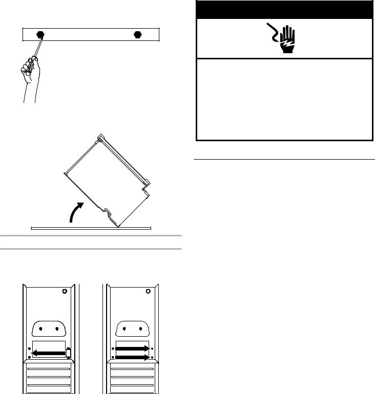
1.Unplug the ice maker or disconnect power.
2.Remove the screws attaching top and bottom hinge covers using an 3/16" hex driver.
A
A.Hinge cover
3.Using pliers, remove the hinge covers from the top and bottom hinges.
NOTE: Save the hinge covers for future use. Reinstall the hinge covers if product is removed from cabinet installation.
4.Lay down the ice maker as shown in the illustration. Be sure to cover the floor with cardboard or hardboard to avoid damaging it.
5.Remove the screws holding the stainless steel panel from the bottom of the door. Set the stainless steel panel and screws aside. For custom panel model, Remove the screws and the top metal bracket using the Phillips screwdriver.
Place them aside.
6.Remove the plastic screw cover from the inside of the hinges and set aside.
7. Remove the top and bottom plastic end caps from the door.
5

8.Unscrew the door hinge screws completely from top and bottom hinges and place them aside.
9.Remove the door and place it aside. Swap the hinge screws to the opposite side.
10.Remove the screws and hinges from the cabinet with the Torx T25 screwdriver and place them aside.
 WARNING
Crush Hazard
Articulated hinges are self closing and many pinch points exist prior to cabinet installation.
Do not operate, or close, the hinges while they are removed from the ice maker.
Failure to follow these instructions can result in crush, cut, or pinch injuries.
†Torx,T20 and T25 are trademarks of Acument Intellectual Properties, LLC.
11. Remove the screw cap cover and replace on the other side.
Preparing the Bottom Hinges
1.Unscrew and remove the grill cover using a Torx T20 screwdriver. Place them aside.
A
A.Grill cover screws
2.Remove the screw cover and place it on the other side as shown in the illustration.
3. Reinstall the grill cover.
6

Reversing the Hinges and End Caps
1.Install the hinge screws (placed aside in step 10 of “Door Panel and Hinge Removal”) half way on the desired side of the cabinet.
2.Take the original top hinge, flip it and place it in the bottom hinge position on the opposite side. Slide onto the cabinet hinge screws. The hinge tabs on the hinges should always face towards each other.
A
A.Hinge tab
3.Take the original bottom hinge, flip it and place it in the top hinge position on the opposite side. Slide onto the cabinet hinge screws.
4. Fully tighten the top and bottom hinge screws.
Final Door Placement
NOTE: Before placing the door back on the ice maker, check all installed parts to ensure there are no exposed screws, all screw cover caps are on, and the door is facing the correct way with the stainless steel door facing out.
1.Slide the door onto the hinges. Using Torx T25 screwdriver install the screws (removed in the step 6 of “Removing the Hinges” section) onto the door.
2.Reinstall the plastic screw cover to original locations on the hinges.
3.Reinstall the top and bottom end caps on the door (the top right end cap is now the bottom left end cap and vice versa). NOTE: For custom wood install skip this step.
4.Place the steel door panel back on the door once all screws are tightened. For custom door panel, skip this step.
7
5.Screw the two hex heads screws back in at the bottom of the door. For custom door panel, skip this step.
6. Return the ice maker back to upright position.
Reverse Door Catch
1.Remove the white decorative screws from the opposite side of the door and set aside.
2.Remove the screws from the magnetic door catch and place them on the opposite side of the door.
3.Install the white decorative screws on the opposite side of the door.
 WARNING
Electrical Shock Hazard Plug into a grounded 3 prong outlet. Do not remove ground prong.
Do not use an adapter.
Do not use an extension cord.
Failure to follow these instructions can result in death, fire, or electrical shock.
4. Plug into a grounded 3 prong outlet.
Drain Pump Installation (on some models)
NOTES:
■■ Connect drain pump to your drain in accordance with all state and local codes and ordinances.
■■ It may be desirable to insulate drain tube thoroughly up to drain inlet to minimize condensation on the drain tube. Insulated tube kit Part Number W10365792 is available for purchase.
■■ Drain pump is designed to pump water to a maximum height of 10 ft (3 m). Use only Whirlpool approved drain pump kit Part Number 1901A.
■■ Do not connect the outlet end of the drain tube to a closed pipe system to keep drain water from backing up into the ice maker.
Kit Contains:
■■ Drain pump kit Part Number 1901A
■■ 5/8" I.D. x 51/8" drain tube (ice maker bin to drain pump reservoir inlet)
■■ 1/2" I.D. x 10 ft (3 m) drain tube hose (drain pump discharge to household drain)
■■ 5/16" I.D. x 32" (81 cm) vent tube (drain pump reservoir vent to ice maker cabinet back)
■■ Cable tie (secures vent tube to back of ice maker) (1)
■■ #8-32 x 3/8" pump mounting screws (secures drain pump to baseplate and clamps to back of ice maker) (5)
■■ 5/8" small adjustable hose clamp (secures vent to drain pump)
■■ 7/8" large adjustable hose clamp, (secures drain tube to ice maker bin and drain pump reservoir inlet) (3)
■■ Rear panel (2) ■■ Instruction sheet
8

If Ice Maker Is Currently Installed
NOTE: If ice maker is not installed, please proceed to “Drain Pump Installation” section.
1. Push the selector switch to the OFF position.
 WARNING
Electrical Shock Hazard Disconnect power before servicing.
Replace all parts and panels before operating.
Failure to do so can result in death or electrical shock.
2.Unplug ice maker or disconnect power.
3.Turn off water supply. Wait 5 to 10 minutes for the ice to fall into the storage bin. Remove all ice from bin.
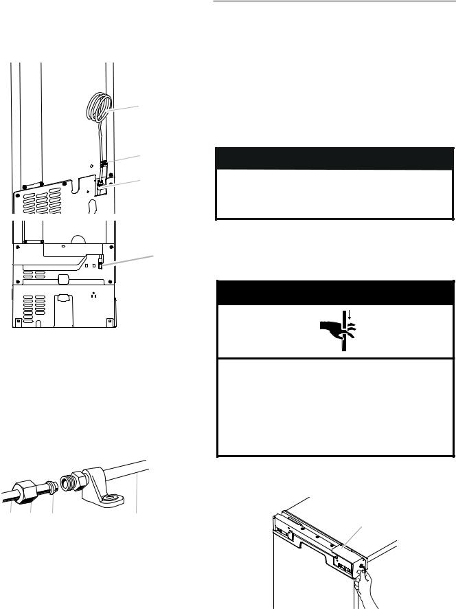
4.Unscrew the drain cap from the bottom of the water pan located inside the storage bin. Allow water to drain
completely. Replace drain cap. See “Drain Cap” illustration.
Drain Cap
A 
A.Drain cap
5.If ice maker is built into cabinets, pull ice maker out of the opening.
6.Disconnect water supply line. See “Water Supply Line” illustration.
Water Supply Line
|
A |
B |
|
|
|
|
|
C |
|
B |
D |
|
|
|
|
C |
|
|
E |
|
A. 1/4" copper tubing |
D. Ferrule (sleeve) |
|
B. Cable clamp |
E. Ice maker connection |
|
C. 1/4" compression nut |
|
|
Drain Pump Installation
NOTE: Do not kink, smash or damage tubes or wires during installation.
1.Unplug ice maker or disconnect power.
2.Remove rear panel. See “Rear Panel” illustration for screw locations. Pull rear panel away from the drain tube. For standard model discard the rear panel. For Custom panel model, set aside the rear panel (it will be reused in step 17).
Rear Panel
A
B
A
A.Screw locations for standard model
B.Screw locations for custom panel model
3.Remove the old drain tube and clamp attached to the ice maker bin.
NOTE: Discard old drain tube and clamp.
4.Slide drain pump into the ice maker base on the right side. The pump mounting tab should slip into the rectangular slot in the ice maker base. It will be necessary to tip the pump slightly to slip into the slot. See “Drain Pump Mounting Tab Slot” illustration.
Drain Pump Mounting Tab Slot
 A
A
A. Mounting tab slot
Drain Pump Installed
A
A. Drain pump installed
9
5.Align the 2 screw holes at the rear of the pump. Use two #8-32 x 3/8" screws, supplied. See “Parts Locations” illustration.
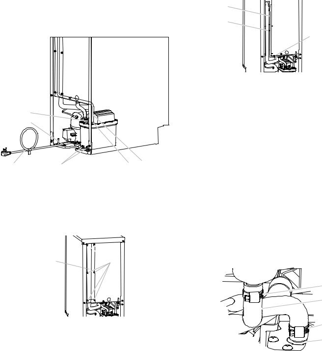
6.Install vent tube (5/16" I.D. x 32" [81 cm]) to drain pump reservoir vent behind the wiring cover. Use supplied 5/8" small adjustable clamps. See “Parts Locations” illustration. Use plastic retainer to keep vent hose secure to top of inner deck. NOTE: Do not install household drain tube this time.
Parts Locations
Vent Tube
NOTE: Do not pinch, kink or damage the vent tube. Check that it is not damaged or pinched or kinked between the cabinet and the ice maker.
A
B
C
I 
H 
C
G
EF
A.Vent tube
B.5/8" hose clamp
C.Drain pump discharge tube
D.Drain pump
E.Ice maker unit power cord
 D B A
D B A
F.#8-32 x 3/8" pump mounting screws
G.Drain pump power cord, clamp and screw
H.Plastic retainer
I.Wiring cover
7.Remove wiring cover. Refer following illustration for location of the screws.
A 
 B
B
A.Wiring cover
B.Screws
8.Route vent tube through plastic retainer that is located underneath top deck in open pump area as shown in illustration. Using cable tie, tie the vent tube to the black suction tube which is located behind the wiring cover. Refer "Vent Tube" illustration.
A.Vent tube
B.Cable ties
C.Plastic retainer
9.Secure wiring cover back in place.
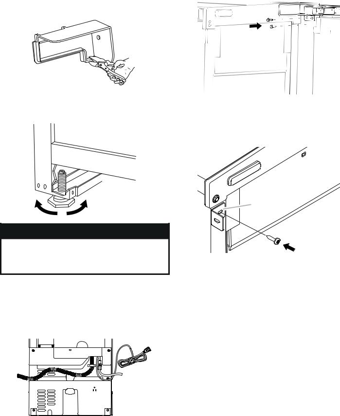
10.Remove power cord clamp and ground screw attached to ice maker power cord, which is mounted to the unit base. See “Parts Locations” illustration.
NOTE: Clamp and screw will be reused.
11.Coil ice maker power cord into a 4" (10.2 cm) diameter coil. Wrap electrical tape around the power cord in several places to keep the cord in a coil. Locate coiled power cord
between the drain pump and side of enclosure and plug into the receptacle of the drain pump. See “Parts Locations” illustration.
12.Attach the drain pump power cord to ice maker unit base with clamp and screw (removed in Step 6) that was used to attach ice maker power cord. See “Parts Locations” illustration.
13.Install new drain tube (5/8" I.D. x 5¹⁄8") from ice maker bin to drain pump reservoir inlet using new adjustable clamps. See “Drain Tube” illustration.
NOTES:
■■ Do not kink.
■■ Trim tube length if required.
Drain Tube
|
A |
|
B |
|
C |
|
D |
A. 7/8" adjustable hose clamp |
C. 7/8" adjustable hose clamp |
B. Drain tube (ice bin to drain pump) |
D. Drain pump reservoir inlet |
10
14.Attach 1/2" I.D. x 10 ft (3 m) drain tube to pump discharge tube. See “Parts Locations” illustration.
NOTE: Do not connect outlet end of drain tube to a closed pipe system to keep drain water from backing up into the ice maker.
For standard model, skip to step 17.
15.Install the cable tie on the rear panel using two holes provided on the rear panel.
A |
A.Holes to fix the cable tie
16.Using a cable tie, fix the drain tube to rear panel.
17.For standard model, place new rear panel (small one for 15" ice makers, large one for 18") against the back of the ice maker. For custom panel model, reuse the plastic rear panel (removed in step 2). Route the vent tube and drain pump discharge tube through cutouts in the rear panel.
18.Secure rear panel with original screws. See “Rear Panel” illustration.
19.Check all connections for leaks.
Connect Water Supply
Read all directions before you begin.
IMPORTANT:
■■ Connect to potable water only.
Do not use with water that is microbiologically unsafe or of unknown quality without adequate disinfection before or after the system. Systems certified for cyst reduction may be used on disinfected waters that may contain filterable cysts.
■■ Plumbing shall be installed in accordance with the International Plumbing Code and any local codes and ordinances.
■■ Use copper tubing or Whirlpool supply line, Part Number 8212547RP, and check for leaks.
■■ Install tubing only in areas where temperatures will remain above freezing.
Tools Needed:
Gather the required tools and parts before starting installation:
■■ 7/16" and 1/2" open-end wrenches or two adjustable wrenches
NOTE: Do not use a piercing-type or 3/16" (4.76 mm) saddle valve which reduces water flow and clogs more easily.
Connecting the Water Line
1.Turn off main water supply. Turn on nearest faucet long enough to clear line of water.
2.Using a 1/2" copper supply line with a quarter-turn shutoff valve or the equivalent, connect the ice maker as shown.
NOTE: To allow sufficient water flow to the ice maker a minimum 1/2" diameter home supply line is recommended.

 A
A


 B
B
A.Bulb
B.Nut
3.Now you are ready to connect the copper tubing. Use 1/4" (6.35 mm) O.D. soft copper tubing for the cold water supply.
■■ Ensure that you have the proper length needed for the job.
Be sure both ends of the copper tubing are cut square.
■■ Slip compression sleeve and compression nut on copper tubing as shown. Insert end of tubing into outlet end squarely as far as it will go. Screw compression nut onto outlet end with adjustable wrench. Do not overtighten.
■■ For custom panel install, be sure there water line extends 30" beyond the cabinet for future servicing purpose
 A
A
B
C
A. Compression sleeve |
C. Copper tubing |
B.Compression nut
4.Place the free end of the tubing into a container or sink, and turn on main water supply and flush out tubing until water is clear. Turn off shutoff valve on the water pipe.
IMPORTANT: Always drain the water line before making the final connection to the inlet of the water valve to avoid possible water valve malfunction.
11
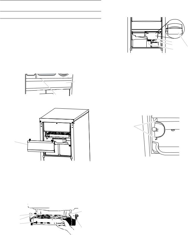
5.Water inlet tube is located on the rear side of the ice maker as shown in "Rear View" illustration. Bend the copper tubing to match with water line inlet. Leave the coil of copper tubing as it is to allow the ice maker to be pulled out of the cabinet or away from the wall for service.
Rear View
A
 B
B
C
D |
A. Copper tubing |
C. Inlet water tube clamp and |
B. Water supply tube clamp |
supply line connector for |
|
standard model |
|
D. Inlet water tube for custom |
|
panel model |
6.Remove and discard the short, plastic tube from the end of the water line inlet.
7.Thread the nut onto the end of the tubing. Tighten the nut by hand. Then tighten it with a wrench two more turns. Do not overtighten.
NOTE: To avoid rattling, be sure the copper tubing does not touch the cabinet’s side wall or other parts inside the cabinet.
A |
B |
C |
D |
A. Line to ice maker |
|
C. Compression sleeve |
|
B. Compression nut |
|
D. Supplied line from ice maker |
|
8.Install the water supply tube clamp around the water supply line to reduce strain on the coupling. For custom panel models, skip this step.
9.Turn shutoff valve ON.
10.Check for leaks. Tighten any connections (including connections at the valve) or nuts that leak.
Leveling and Securing
It is important for the ice maker to be level in order to work properly. Depending upon where you install the ice maker, you may need to make several adjustments to level it. You may also use the leveling legs to lower the height of the ice maker for undercounter installations.
Tools Needed
Gather the required tools and parts before starting installation. ■■ Level
■■ Adjustable wrench
NOTE: It is easier to adjust the leveling legs if you have another person to assist you.
 WARNING
Excessive Weight Hazard
Use two or more people to move and install ice maker. Failure to do so can result in back or other injury.
1.Move the ice maker in front of its final location. Be sure to cover the floor with cardboard or hardboard to avoid damaging it.
NOTE: If this is a built-in installation, move the ice maker as close as possible to the final location.
 WARNING
Crush Hazard
Articulated hinges are self closing and many pinch points exist prior to cabinet installation.
Do not remove hinge covers until product is ready to be installed.
Failure to follow these instructions can result in crush, cut, or pinch injuries.
2.Remove the screws attaching top and bottom hinge covers using an 3/16" hex driver.
A
A. Hinge cover
12
3.Using pliers, remove the hinge covers from the top and bottom hinges.
NOTE: Save the hinge covers for future use. Reinstall the hinge covers if product is removed from cabinet installation.
4.For custom panel installation, install the door panel according to the instructions in the “Custom Wood Panel” section.
5.Use ice maker leveling legs to align ice maker door to the adjacent cabinet opening.
7.Be sure that the ice maker is at desired depth. Secure the top and bottom hinges to the side of the cabinet using wood screws.
8.Attach the cabinet brackets (provided with ice maker) to the holes in the front of ice maker as shown in the illustration. Attach the cabinet brackets to the side of the cabinet with wood screws.
NOTE: For the custom wood panel installation, continue installation at step 7 of “Custom wood panel installation.”
 WARNING
Excessive Weight Hazard
Use two or more people to move and install ice maker. Failure to do so can result in back or other injury.
6.Slide ice maker into the cabinet while managing the utility connection positions behind the ice maker. Be sure to cover the floor with cardboard or hardboard to avoid damaging it.
IMPORTANT: For the custom panel model flush install, the ice maker utility connections must be routed out through the slot in the ice maker rear panel. Any time ice maker is removed for service, do the same process when placing the unit back in the cabinets.
A
A. Cabinet bracket
13

Custom Wood Panel
Custom Panel Dimensions
If you plan to install a custom overlay panel, you will need to make the panel yourself or consult qualified cabinetmaker or carpenter
IMPORTANT:
■■ The thickness of overlay panel must be 3/4" (1.91 cm). ■■ Overlay panel must not weigh more than 8lbs (3.62 kg).
■■ Overlay panels weighing more than recommended may cause damage to your ice maker.
■■ Match wood grain direction with that of adjacent cabinets. ■■ Sand panel edges to provide a smooth finish.
■■ Use moisture sealer on both sides and all edges of the panel to avoid damage from outside.
Option 1 - Without Hinge-Side Spacer
To allow proper clearance for the door, prepare the custom overlay panel using the dimension shown.
29¹⁄"
(74.9 cm)
14¹ ⁄"
(36.9 cm)
|
|
|
|
|
1¹⁄ " |
|
|
|
1¹⁄ " |
||||||||
|
|
|
|
(3.18 cm) |
|
|
(3.18 cm) |
||||||||||
|
|
|
|
|
3/4" |
3/4" |
|
|
|
|
|
|
|
|
|||
|
|
|
|
|
|
|
|
|
|
|
|
|
|
|
|
||
|
|
|
|
|
|
|
|
|
|
|
|
|
|
|
|
||
|
|
|
|
|
|
|
|
|
|
|
|
|
|
|
|
||
1/4" |
|
|
|
|
|
|
|
(1.91 mm) |
(1.91 mm) |
|
|
|
|
|
|
|
1/4" |
|
|
|
|
|
|
|
|
|
|
|
|
|
|
||||
(6.35 mm) |
|
|
|
|
|
|
|
|
|
|
|
|
|
|
|
|
(6.35 mm) |
|
|
|
|
|
|
|
|
|
|
|
|
|
|
|
|
||
Option 2 - With Hinge-Side Spacer
To achieve a flush installation with adjacent cabinets, prepare the custom overlay panel using the dimensions shown.
29¹⁄"
(74.9 cm)
14⁄"
(37.1 cm)
Top of Panel
A B
A.Front-visible surface when installed
B.Hinge Side
Bottom of Panel
A B
A.Front-visible surface when installed
B.Hinge Side
14

Custom Panel Installation
1.Remove screws and the top metal bracket using the Phillips screwdriver. Remove and place them aside. Skip this step and go to the step 4 if the door reversal has been completed.
2.Remove the top and bottom end caps using the Phillips screwdriver and place them aside.
3.Reinstall top metal bracket using screws removed in the step 1.
4.Lightly press the custom panel onto the door using double sided adhesive tape. Adjust height of the panel to align with the adjacent cabinetry. Press the panel firmly against door.
5.From inside the door, install the wood screws through the slotted holes in the metal brackets.
Continue to “Leveling and Securing” section at step 5.
6.Adjust the panel side to side to achieve a desired gap on both sides. Install the remaining screws through the door bracket into the panel.
NOTE: Be sure that the panel is aligned with adjacent cabinet before installing the remaining screws to secure the door panel.
7.Replace the top and bottom end caps into the door. Fix the bottom end cap using screw through the bottom metal bracket hole.
15

Connecting the Drain
After ensuring that the drain system is adequate, follow these steps to properly place the ice maker:
 WARNING
Excessive Weight Hazard
Use two or more people to move and install ice maker. Failure to do so can result in back or other injury.
1.Style 1—For a gravity drain system, be sure that the ice maker drain tube is positioned over the PVC drain reducer. See the “Gravity Drain System” section.
Style 2—For a drain pump system, connect the drain pump outlet hose to the drain. Refer the “Drain Supply Requirements” section.
NOTE: Do not connect outlet end of drain tube to a closed pipe system to avoid drain water from backing up into the ice maker.
 WARNING
Electrical Shock Hazard Plug into a grounded 3 prong outlet. Do not remove ground prong.
Do not use an adapter.
Do not use an extension cord.
Failure to follow these instructions can result in death, fire, or electrical shock.
2.Plug in ice maker or reconnect power.
3.Turn on ice maker. Wait for rinsing cycle, approximately 5 minutes, to be sure the ice maker is operating properly.
4.If it is required by your local sanitation code, seal the cabinet to the floor with an approved caulking compound after all water and electrical connections have been made.
Auxiliary Grill Installation
The auxiliary grill is an optional part that can be used to align the toe grill with the rest of the cabinets (while not obstructing ventilation of the ice maker).
Tools required:
■■ Torx T20 screwdriver
■■ 1/8" straight drill bit and power drill
1.First, complete all installation steps and install leveled ice maker into the cabinet. Ensure ice maker is flush with the adjacent cabinets.
2.Unpack kit by removing outer cushion packaging and discard packaging material.
3.Remove screws that are taped onto the inside of the auxiliary grill.
4.Place grill onto cabinetry. Align part so that grating pattern on the auxiliary grill matches that of the toe grill on the ice maker.
5.Center auxiliary grill on cut out for ice maker. Mark hole locations on each side of auxiliary grill on cabinet.
6.Using power drill and a 1/8" drill bit, drill holes in cabinet. This is to fit screws of size 8-18 x 0.750.
7.Using the Torx T20 screwdriver, screw auxiliary grill into cabinet.
NOTE: For future service of ice maker, auxiliary kit must be removed prior to the removal of the ice maker from the cabinets.
16
Deep Clean
Interior Components
1. |
Unplug ice maker or disconnect power. |
2. |
Open the storage bin door and remove any ice that is in the |
|
bin. |
3. |
Remove the drain cap from the water pan and drain |
|
thoroughly. Replace the drain cap securely on the water pan. |
|
If the drain cap is loose, water will empty from the water pan, |
|
and you will have either thin ice or no ice. |
4. |
Pull out on the bottom of the cutter grid cover until the snaps |
|
release to remove. |
|
NOTE: On some models, remove the screw from the cutter |
|
grid cover. |
5. |
Unplug the wiring harness from the left side of the cutter grid. |
|
A |
|
B |
|
A. Cutter grid cover |
|
B. Screw (on some models) |
A
A.Cutter grid cover
6.Unplug the ice level sensor from the right side of the cutter grid. Pull the ice level sensor down and forward away from the cutter grid.
7.Remove the right-hand and left-hand screws. Lift the cutter grid up and out.
NOTE: Make sure the plastic spacer from the right-hand side of the cutter grid bracket stays with the cutter grid.
A


B


C


A.Cutter grid harness
B.Screw
C.Cutter grid
D

 E
E
F
D.Ice level sensor harness
E.Plastic spacer
F.Screw
8.Remove the mounting screw that holds the water pan in place. Pull out on the front of the water pan.
9.Disconnect the pump bracket from the water pan and unplug the water pan drain pump.
|
A |
|
|
B |
D |
|
C |
|
|
|
|
A. Water pan |
C. Drain cap |
|
B. Water pan screw |
D. Drain pump cover |
|
10.Remove, clean and replace the ice scoop holder and ice scoop.
NOTE: On some models, the ice scoop holder is located in the upper left of the unit, and on other models, the ice scoop holder is located in the lower left of the unit.
On Some Models
■■ Remove the holder by removing the 2 screws.
■■ Wash the ice scoop holder and ice scoop along with the other interior components using the following instructions.
■■ Replace the ice scoop holder by replacing the screws.
A
 B
B
A.Screw
B.Ice scoop holder
On Some Models
■■ After removing the ice scoop, remove the holder by removing the 2 screws.
NOTE: On some models, remove the holder by lifting up on the ice scoop holder and then out.
17
Loading...