


30" (76.2 CM) AND 36" (91.4 CM)
RETRACTABLE (POP-UP) DOWNDRAFT VENT
SYSTEM
InstallationInstructionsandUse&CareGuide
For questions about features, operation/performance, parts, accessories or service, call: 1-800-422-1230
In Canada, for assistance, installation and service, call: 1-800-807-6777
or visit our website at...
www.kitchenaid.com or www.KitchenAid.ca
SYSTÈME DE VENTILATION RÉTRACTABLE (CLAPET) DE 30" (76,2 CM) ET 36" (91,4 CM)— ASPIRATION PART LE BAS
Instructionsd’installationetGuided’utilisationetd’entretien
Au Canada, pour assistance, installation ou service composez le 1-800-807-6777
ou visitez notre site web à...
www.KitchenAid.ca
Table of Contents/Table des matières............................................................................. |
2 |
IMPORTANT: READ AND SAVE THESE INSTRUCTIONS.
FOR RESIDENTIAL USE ONLY.
IMPORTANT : LIRE ET CONSERVER CES INSTRUCTIONS.
POUR UTILISATION RÉSIDENTIELLE UNIQUEMENT.
LI3ZTB/W10342489E

TABLE OF CONTENTS
VENT SYSTEM SAFETY................................................................. |
3 |
Install Downdraft Vent In-Line |
|
||
INSTALLATION REQUIREMENTS |
5 |
(External Type) Blower Motor..................................................... |
18 |
||
Make Electrical Connections |
|
||||
|
Tools and Parts |
5 |
|
||
|
for In-Line Blower Motor System |
20 |
|||
|
Location Requirements |
5 |
|||
|
Make Electrical Power Supply Connection |
|
|||
|
Electrical Requirements |
8 |
|
||
|
to Downdraft Vent |
21 |
|||
|
Venting Requirements |
8 |
|||
|
Check Operation |
22 |
|||
INSTALLATION INSTRUCTIONS |
|
||||
|
VENT SYSTEM USE |
23 |
|||
INTERIOR-MOUNTED VENT MOTOR |
9 |
||||
Operating Downdraft Vent |
23 |
||||
|
Venting Methods |
9 |
|||
|
VENT SYSTEM CARE |
24 |
|||
|
Install Vent System..................................................................... |
11 |
|||
|
Rear Mounting—Blower Motor.................................................. |
12 |
Surface of Downdraft Vent......................................................... |
24 |
|
|
Complete Installation (Interior-Mounted Motor) ........................ |
13 |
Filters .......................................................................................... |
24 |
|
|
Make Electrical Connections ..................................................... |
15 |
WIRING DIAGRAMS..................................................................... |
25 |
|
|
Check Operation ........................................................................ |
15 |
Interior-Mounted Blower Motor ................................................. |
25 |
|
INSTALLATION INSTRUCTIONS |
|
Exterior-Mounted Blower Motor ................................................ |
26 |
||
|
ASSISTANCE OR SERVICE |
27 |
|||
EXTERIOR-MOUNTED VENT MOTOR....................................... |
16 |
||||
|
Venting Methods ........................................................................ |
16 |
In the U.S.A. ............................................................................... |
27 |
|
|
Install Vent System..................................................................... |
17 |
In Canada ................................................................................... |
27 |
|
|
Complete Installation (Exterior-Mounted Motor) ....................... |
18 |
Accessories ................................................................................ |
27 |
|
|
|
|
WARRANTY .................................................................................. |
28 |
|
|
|
|
|
|
|
TABLE DES MATIÈRES
SÉCURITÉ DU SYSTÈME DE VENTILATION............................. |
29 |
EXIGENCES D'INSTALLATION................................................... |
31 |
Outils et pièces........................................................................... |
31 |
Exigences d'emplacement......................................................... |
31 |
Spécifications électriques .......................................................... |
35 |
Exigences concernant l’évacuation ........................................... |
35 |
INSTRUCTIONS D’INSTALLATION |
|
VENTILATEUR MONTÉ À L’INTÉRIEUR .................................... |
36 |
Méthodes d’évacuation ............................................................. |
36 |
Installation du conduit d’évacuation.......................................... |
37 |
Montage du ventilateur à l’arrière .............................................. |
39 |
Achever l’installation .................................................................. |
40 |
Raccordements électriques ....................................................... |
41 |
Contrôle du fonctionnement ...................................................... |
42 |
INSTRUCTIONS D’INSTALLATION |
|
VENTILATEUR MONTÉ À L’EXTÉRIEUR................................... |
43 |
Méthodes d’évacuation ............................................................. |
43 |
Installation du conduit d’évacuation.......................................... |
44 |
Achever l’installation (Ventilateur monté à l’extérieur)............... |
45 |
Installation du ventilateur en ligne |
|
(type externe) du système d’extraction par le bas..................... |
45 |
Raccordements électriques |
|
du système de ventilation en ligne............................................. |
47 |
Raccordement de l’alimentation électrique |
|
au système d’extraction par le bas............................................ |
48 |
Contrôle du fonctionnement ...................................................... |
49 |
UTILISATION DU SYSTÈME D’EXTRACTION ........................... |
50 |
Utilisation du système d’extraction par le bas........................... |
50 |
ENTRETIEN DU SYSTÈME D’ÉVACUATION ............................. |
51 |
Surface du système d’extraction par le bas .............................. |
51 |
Filtres .......................................................................................... |
51 |
SCHÉMA DE CÂBLAGE............................................................... |
52 |
Ventilateur monté à l'intérieur .................................................... |
52 |
Ventilateur monté à l'extérieur ................................................... |
53 |
ASSISTANCE OU SERVICE......................................................... |
54 |
Aux États-Unis............................................................................ |
54 |
Au Canada.................................................................................. |
54 |
Accessoires ................................................................................ |
54 |
GARANTIE..................................................................................... |
55 |
2
VENT SYSTEM SAFETY
Your safety and the safety of others are very important.
We have provided many important safety messages in this manual and on your appliance. Always read and obey all safety messages.
This is the safety alert symbol.
This symbol alerts you to potential hazards that can kill or hurt you and others.
All safety messages will follow the safety alert symbol and either the word “DANGER” or “WARNING.” These words mean:
 DANGER
 WARNING
You can be killed or seriously injured if you don't immediately follow instructions.
You can be killed or seriously injured if you don't follow instructions.
All safety messages will tell you what the potential hazard is, tell you how to reduce the chance of injury, and tell you what can happen if the instructions are not followed.
3

IMPORTANT SAFETY INSTRUCTIONS
WARNING: TO REDUCE THE RISK OF FIRE, ELECTRIC SHOCK, OR INJURY TO PERSONS, OBSERVE THE FOLLOWING:
■Use this unit only in the manner intended by the manufacturer. If you have questions, contact the manufacturer.
■Before servicing or cleaning the unit, switch power off at service panel and lock the service disconnecting means to prevent power from being switched on accidentally. When the service disconnecting means cannot be locked, securely fasten a prominent warning device, such as a tag, to the service panel.
■Installation work and electrical wiring must be done by qualified person(s) in accordance with all applicable codes and standards, including fire-rated construction.
■Do not operate any fan with a damaged cord or plug. Discard fan or return to an authorized service facility for examination and/or repair.
■Sufficient air is needed for proper combustion and exhausting of gases through the flue (chimney) of fuel burning equipment to prevent backdrafting. Follow the heating equipment manufacturer's guideline and safety standards such as those published by the National Fire Protection Association (NFPA), the American Society for Heating, Refrigeration and Air Conditioning Engineers (ASHRAE), and the local code authorities.
■When cutting or drilling into wall or ceiling; do not damage electrical wiring and other utilities.
■Ducted fans must always be vented outdoors.
CAUTION: For general ventilating use only. Do not use to exhaust hazardous or explosive materials and vapors.
CAUTION: To reduce risk of fire and to properly exhaust air, be sure to duct air outside - do not vent exhaust air into spaces within walls or ceilings, attics or into crawl spaces, or garages.
WARNING: TO REDUCE THE RISK OF FIRE, USE ONLY METAL DUCTWORK.
WARNING: TO REDUCE THE RISK OF A RANGE TOP GREASE FIRE:
■Never leave surface units unattended at high settings. Boilovers cause smoking and greasy spillovers that may ignite. Heat oils slowly on low or medium settings.
■Always turn hood ON when cooking at high heat or when flambeing food (i.e. Crepes Suzette, Cherries Jubilee, Peppercorn Beef Flambé).
■Clean ventilating fans frequently. Grease should not be allowed to accumulate on fan or filter.
■Use proper pan size. Always use cookware appropriate for the size of the surface element.
WARNING: TO REDUCE THE RISK OF INJURY TO PERSONS IN THE EVENT OF A RANGE TOP GREASE FIRE, OBSERVE THE FOLLOWING:a
■SMOTHER FLAMES with a close fitting lid, cookie sheet, or metal tray, then turn off the burner. BE CAREFUL TO PREVENT BURNS. If the flames do not go out immediately, EVACUATE AND CALL THE FIRE DEPARTMENT.
■NEVER PICK UP A FLAMING PAN - you may be burned.
■DO NOT USE WATER, including wet dishcloths or towels - a violent steam explosion will result.
■Use an extinguisher ONLY if:
–You know you have a class ABC extinguisher, and you already know how to operate it.
–The fire is small and contained in the area where it started.
–The fire department is being called.
–You can fight the fire with your back to an exit.
aBased on "Kitchen Fire Safety Tips" published by NFPA.
■ WARNING: To reduce the risk of fire or electrical shock, do not use this fan with any solid-state speed control device.
READ AND SAVE THESE INSTRUCTIONS
4

INSTALLATION REQUIREMENTS
ToolsandParts
Gather the required tools and parts before starting installation. Read and follow the instructions provided with any tools listed here.
Tools Needed
■Jigsaw or keyhole saw
■Drill
■¹⁄ " (3 mm) drill bit for pilot holes
■Pencil
■Tape measure or ruler
■Flat-blade screwdriver
■Phillips screwdriver
■³⁄ " (9.5 mm) nut driver
■Level
■Pliers
■Metal snips
■Wire stripper or utility knife
■Caulking gun and weatherproof caulking compound
Parts Supplied
■Top trim - stainless
■2 - End caps
■2 - Lower support legs
■2 - Undercounter mounting brackets
■16 - 4 x 8 mm screws
■3 - 3.5 x 9.5 mm screws
■3¹⁄ " x 10" (8.3 x 25.4 cm) rectangular damper
■4³⁄ " (12.0 cm) motor box
■¹⁄ " (6.4 mm) deep cover
■Flat vent cover plate
■6" (15.2 cm) diameter vent transition with damper (interiormounted blower motor models only)
■10" (25.4 cm) diameter vent collar (exterior-mounted blower model only)
Parts Needed
■UL listed or CSA approved ½" (12.7 mm) conduit connector
■Wall or roof cap with damper to match vent system
■Vent system
■Home power supply cable
■3 - UL listed wire connectors
■Wiring cable for optional remote blower kit
■Vent clamps/duct tape as required
LocationRequirements
NOTE: Downdraft vent is installed directly behind the cooktop. Install the downdraft vent first, then install the cooktop.
IMPORTANT: Observe all governing codes and ordinances.
■Have a qualified technician install the downdraft vent. It is the installer’s responsibility to comply with installation clearances specified on the model/serial rating plate. The model/serial rating plate is located on the front of the downdraft vent above the terminal box cover.
■Downdraft vent location should be away from strong draft areas, such as windows, doors, and strong heating vents or fans.
■Cabinet opening dimensions that are shown must be used. Given dimensions provide minimum clearance.
■Consult the cooktop manufacturer installation instructions before making any cutouts.
Check that the downdraft vent and cooktop location will clear the cabinet walls, backsplash, and rear wall studs inside the cabinet.
Check for the minimum distance between the front edge of the countertop and the front edge of the cooktop. The minimum horizontal distance between the overhead cabinets is the same as the width of the installed downdraft vent.
■All openings in ceiling and wall where the downdraft vent will be installed must be sealed.
■Grounded electrical outlet is required. See “Electrical Requirements” section.
■When installing the downdraft vent, the cabinet drawer will need to be removed and the drawer front installed permanently to the cabinet.
Cabinet Construction:
Downdraft vent is designed for use in a cabinet with a depth of 24" (61 cm). Some installations require a countertop deeper than 25" (63.5 cm). See the Countertop Cutout Dimensions chart.
The maximum depth of the overhead cabinet is 13" (33 cm). Overhead cabinets installed at either side of the downdraft vent must be 18" (45.7 cm) above the cooking surface.
For Mobile Home Installations
The installation of this downdraft vent must conform to the Manufactured Home Construction Safety Standards, Title 24 CFR, Part 328 (formerly the Federal Standard for Mobile Home Construction and Safety, title 24, HUD, Part 280) or when such standard is not applicable, the standard for Manufactured Home Installation 1982 (Manufactured Home Sites, Communities and Setups) ANSI A225.1/NFPA 501A*, or latest edition, or with local codes.
5

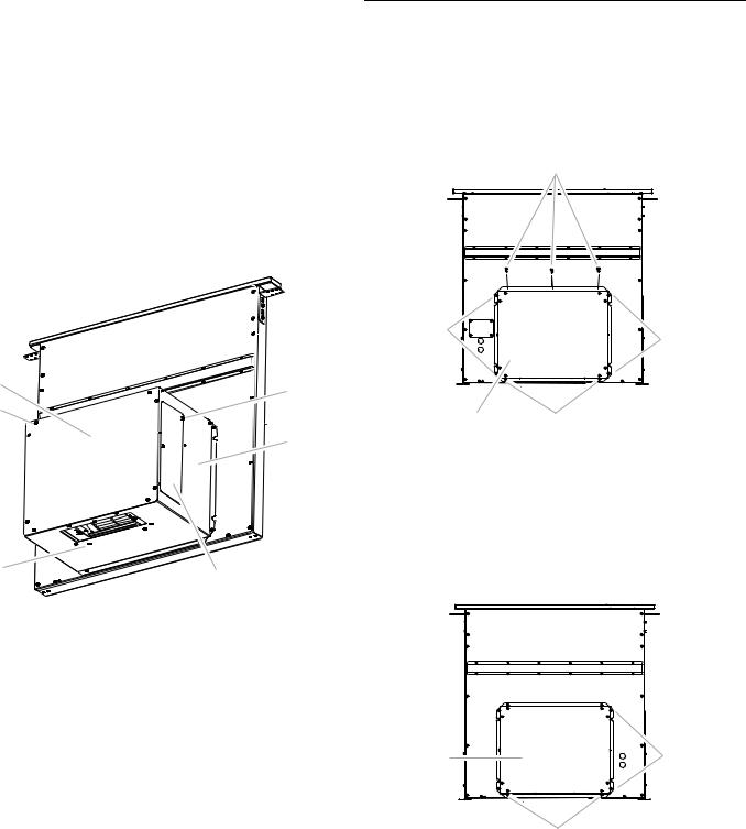
Product Dimensions
Models with interior-mounted blower motor |
Models with exterior-mounted blower motor |
|
Top trim widths: |
|
30" (76.2 cm) |
|
36" (91.4 cm) |
13¹⁄ " (34.3 cm) |
|
retractable |
|
vent height |
|
|
1¹⁄ " (3.8 cm) |
27" (68.6 cm) for 30" (76.2 cm) vent |
³⁄ " (0.95 cm) |
33" (83.8 cm) for 36" (91.4 cm) vent |
|
|
5¹⁄ "(13.3 cm) |
|
for 30" (76.2 cm) vent |
|
8¹⁄ "(21.0 cm) |
|
for 36" (91.4 cm) vent |
|
28¹⁄ " |
13¹⁄ " (33.4 cm) |
(72.4 cm) |
|
|
|
³⁄ |
|
(1.9 cm) |
16¹⁄ " (42.0 cm)
 10" (25.4 cm)
2¹⁄ " (5.4 cm)
As-Received Blower
4³⁄ " (12.1 cm) |
|
|
13¹⁄ " (33.4 cm) |
|
|
6 ⁄ " |
|
|
(16.7 cm) |
|
|
10" (25.4 cm) |
|
|
diameter |
|
|
vent collar |
|
|
8¹⁄ " |
³⁄ " (1.9 cm) |
|
(21.0 cm) |
||
|
||
16¹⁄ " (42.0 cm) |
|
Reversed Blower
Front of |
Range Hood |
10" (25.4 cm) |
Front of
Range Hood
4³⁄ " |
(12 cm) |
10" |
(25.4 cm) |
16¹ ⁄ " (43 cm)
6
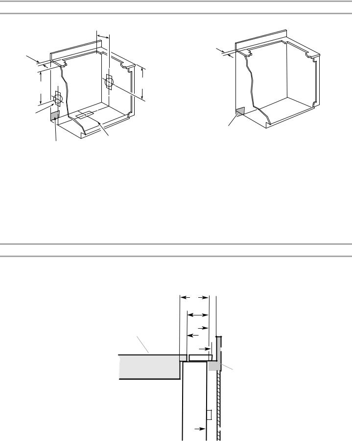
Cabinet Dimensions
Interior-mounted blower motor model
A= ¹⁄ " (12.7 mm) minimum
21 ⁄ "
(54.1 cm)
Cutouts are for 3¹⁄ " x 10"
(8.3 x 25.4 cm) rectangular or 6" (15.2 cm) round vent system.
Locate power supply junction box at lower left hand
rear corner
of the cabinet.
10" (25.4 cm)
21 ⁄ "
(54.1 cm)
Centerline of cooktop cutout
Exterior-mounted blower motor model
¹⁄ " (12.7 mm) minimum
Locate power supply junction box at lower left hand
rear corner
of the cabinet.
NOTES:
■See cooktop manufacturer’s instructions for cooktop cutout depth and width.
■Use dimensions for vent system cutout location that applies to your installation.
■Interior-mounted blower systems connect with 3¹⁄" x 10" (8.3 x 25.4 cm) rectangular or 6" (15.2 cm) round vent system. The cutout locations for this vent system will depend on your specific installation.
NOTES:
■See cooktop manufacturer’s instructions for cooktop cutout depth and width.
■Exterior-mounted blower systems connect with 10" (25.4 cm) round vent. The cutout locations for this vent system will depend upon your specific installation.
Countertop Cutout Dimensions
IMPORTANT: Countertops with a bull-nosed front edge are not recommended for these installations.
Some models require a countertop deeper than 25" (63.5 cm); see the following Countertop Cutout Dimensions Chart.
To avoid mistakes, it is recommended that the cooktop and vent cutouts be drawn on the countertop before making any cutouts.
See Cooktop Installation Instructions for complete cutout dimensions, location dimensions and installation details.
D
E
 F
F
B C 
 G
G

 H
H
A 
 I
I
A. Downdraft vent |
D. D = Measurement of cooktop rear overhang |
G. ¼" (6.4 mm) minimum |
B. Cooktop |
(C) + 1¹³⁄ " [46.2 mm] (E) |
H. Countertop and backsplash |
C. Measurement of cooktop rear overhang. |
E. 1¹³⁄ " (46.2 mm) |
I. ½" (12.7 mm) minimum |
|
F. ½" (12.7 mm) minimum |
|
7

Countertop Cutout Dimensions Chart
B
D
C
A
A.½" (12.7 mm) minimum to backsplash or rear wall
B.³⁄ " (19.1 mm) maximum backsplash depth
C.27¹⁄ " (69.9 cm) on 30" (76.2 cm) models 33¹⁄ " (85.9 cm) on 36" (91.4 cm) models
D.D = Measurement of cooktop rear overhang + 1¹³⁄ " (46.2 mm)
ElectricalRequirements
Observe all governing codes and ordinances.
Ensure that the electrical installation is adequate and in conformance with National Electrical Code, ANSI/NFPA 70 (latest edition), or CSA Standards C22.1-94, Canadian Electrical Code, Part 1 and C22.2 No. 0-M91 (latest edition) and all local codes and ordinances.
If codes permit and a separate ground wire is used, it is recommended that a qualified electrician determine that the ground path is adequate.
A copy of the above code standards can be obtained from:
National Fire Protection Association
1 Batterymarch Park
Quincy, MA 02169-7471
CSA International
8501 East Pleasant Valley Road
Cleveland, OH 44131-5575
■A 120 volt, 60 Hz., AC only, 15-amp, fused electrical circuit is required.
■If the house has aluminum wiring, follow the procedure below:
1.Connect a section of solid copper wire to the pigtail leads.
2.Connect the aluminum wiring to the added section of copper wire using special connectors and/or tools designed and UL listed for joining copper to aluminum.
Follow the electrical connector manufacturer's recommended procedure. Aluminum/copper connection must conform with local codes and industry accepted wiring practices.
■Wire sizes and connections must conform with the rating of the appliance as specified on the model/serial rating plate. The model/serial plate is located on the front of the downdraft vent, above the wiring box cover.
■Wire sizes must conform to the requirements of the National Electrical Code, ANSI/NFPA 70 (latest edition), or CSA Standards C22. 1-94, Canadian Electrical Code, Part 1 and C22.2 No. 0-M91 (latest edition) and all local codes and ordinances.
VentingRequirements
IMPORTANT: Make sure there is proper clearance within the wall or floor before making exhaust vent cutouts.
■Use heavy (rigid) metal vent.
■Venting system must terminate to the outside.
■Do not terminate the vent system in an attic or other enclosed area.
■Do not use 4" (10.2 cm) laundry-type wall caps.
■Do not install 2 elbows together.
■Do not use plastic or metal foil vent.
■The length of vent system and number of elbows should be kept to a minimum to provide efficient performance.
■Use no more than three 90° elbows
■Make sure there is a minimum of 24" (61 cm) of straight vent between the elbows if more than one elbow is used.
■Use clamps or duct tape to seal all joints in the vent system.
■Use caulking tape to seal the exterior wall or floor opening around cap.
■Do not cut joist or stud. If vent cutout falls over a joist or stud, a supporting frame must be constructed.
Flexible metal vent is not recommended. If it is used, calculate each foot of flexible vent as 2 ft (0.6 m) of rigid metal vent.
Flexible elbows count twice as much as standard elbows.
Recommended Vent System Length:
For either interior-mounted or exterior-mounted blower installations, the vent system length should not exceed the maximum lengths listed in the Maximum Length of Vent System chart. See “Calculating Vent System Length” in the “Venting Methods” section in the Installation Instructions for the interioror exterior-mounted vent motor.
Cold Weather Installations
An additional back draft damper should be installed to minimize backward cold air flow and a thermal break should be installed to minimize conduction of outside temperatures as part of the vent system. The damper should be on the cold air side of the thermal break.
The break should be as close as possible to where the vent system enters the heated portion of the house.
Makeup Air
Local building codes may require the use of makeup air systems when using ventilation systems greater than specified CFM of air movement. The specified CFM varies from locale to locale.
Consult your HVAC professional for specific requirements in your area.
8
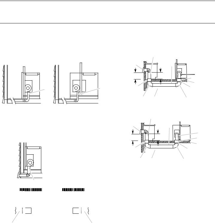
INSTALLATION INSTRUCTIONS INTERIOR-MOUNTED VENT MOTOR
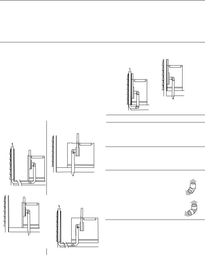
VentingMethods
Determine which venting method is best for your application. Vent system can terminate either through the wall or floor.
Island Location
Front (Standard)-Mounted |
Rear-Mounted Blower |
Blower Motor |
Motor |
A |
A |
|
A. Down vent
NOTE: For island locations, a front or rear mounted blower motor can also be mounted for right or left venting if needed for your application. Most island applications would still require the venting to be directed down through the floor.
Built-In Cabinet Locations
A
|
|
|
|
|
|
|
|
|
|
|
|
|
|
|
|
|
|
C |
|
|
|
|
|
|
|
|
|
|
|
|
|
|
|
|
|
|
|
|
|
|
|
|
|
|
|
|
|
|
|
|
|
|
|
|
|
|
|
|
|
|
|
|
|
|
|
|
|
|
|
|
|
|
|
|
|
|
|
|
|
|
|
|
|
|
|
|
|
|
|
|
|
|
|
|
|
|
|
|
|
|
|
|
|
|
|
|
|
|
|
|
|
|
|
|
|
|
|
|
|
|
|
|
|
|
|
|
|
|
|
|
|
|
|
|
|
|
|
|
|
|
|
|
|
|
|
|
|
|
|
|
|
|
|
|
|
|
|
|
|
|
|
|
|
|
|
|
|
|
|
|
|
|
|
|
|
|
|
|
|
|
|
|
|
|
|
|
|
|
|
|
|
|
|
|
|
|
|
|
|
|
|
|
|
|
|
|
|
|
|
|
|
|
|
|
|
|
|
|
|
|
|
|
|
|
|
|
|
|
|
|
|
|
|
|
|
|
|
|
|
|
|
|
|
|
|
|
|
|
|
|
|
|
|
|
|
|
|
|
|
|
|
|
|
|
|
B |
|
|
|
|
|
|
|
|
|
|
|
|
|
|
|
|||
|
|
|
|
|
|
|
|
|
|
|
|
|
|
|
||||
|
|
|
|
|
|
|
|
|
|
|
|
|
|
|
|
|||
A.Down vent
B.Left vent
C.Right vent
Island Location—Vent System Installed Under a Concrete Slab Using PVC Sewer Pipe
Front (Standard)-Mounted Blower Motor
|
B |
|
|
A |
|
|
D |
|
|
|
|
M |
|
C |
E |
|
F |
||
|
|
|
|
|
|
|
G |
L |
|
|
H |
K |
J |
|
I |
Rear-Mounted Blower Motor |
|
||
|
B |
|
|
A |
|
|
D |
|
|
|
|
|
|
|
E |
M |
|
C |
F |
|
|
|
G |
L |
|
|
H |
K |
J |
|
I |
A.Wall cap
B.6" (15.2 cm) round metal vent
C.16" (40.6 cm) maximum
D.6" (15.2 cm) round PVC sewer pipe
E.6" (15.2 cm) round metal vent transition with damper (supplied) F. 6" (15.2 cm) round PVC coupling
G.Concrete slab
H.6" (15.2 cm) round PVC sewer pipe
I.6" (15.2 cm) round 90° PVC sewer pipe elbow
J.Tightly pack gravel or sand completely around pipe.
K.6" (15.2 cm) round 90° PVC sewer pipe elbow
L.6" (15.2 cm) round PVC coupling
M.12" (30.5 cm) minimum
9
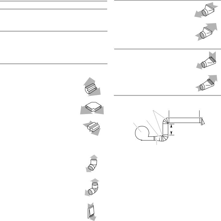
Calculating Vent System Length
3¼" x 10" (8.3 x 25.4 cm) rectangular vent is required from the blower motor box. It can be transitioned to 6" (15.2 cm) round vent if needed.
Maximum Length of Vent System
Vent |
Length |
|
|
6" (15.2 cm) round |
35 ft (8.9 m) |
|
|
3¹⁄ " x 10" (8.3 cm x 25.4 cm) |
35 ft (8.9 m) |
|
|
To calculate the length of the system you need, add the equivalent feet (meters) for each vent piece used in the system.
|
3¹⁄ " x 10" (8.3 cm x 25.4 cm) |
|||||
Vent Piece |
Rectangular |
|||||
|
|
|
|
|
|
|
3¹⁄ " x 10" (8.3 cm x 25.4 cm) |
5.0 ft |
|||||
90° elbow |
(1.5 m) |
|
|
|
|
|
|
||||||
|
|
|
|
|
|
|
3¹⁄ " x 10" (8.3 cm x 25.4 cm) |
12.0 ft |
|||||
flat elbow |
(3.7 m) |
|
|
|
||
|
|
|
||||
|
|
|
|
|
|
|
3¹⁄ " x 10" (8.3 cm x 25.4 cm) |
0.0 ft |
|||||
wall cap |
(0.0 m) |
|||||
|
|
|
|
|
|
|
Vent Piece |
6" (15.2 cm) Round |
|||||
|
|
|
|
|
|
|
45° elbow |
2.5 ft |
|||||
|
(0.8 m) |
|||||
|
|
|
|
|
|
|
90° elbow |
5.0 ft |
|||||
|
(1.5 m) |
|||||
|
|
|
|
|
|
|
6" (15.2 cm) |
0.0 ft |
|||||
wall cap |
(0.0 m) |
|||||
3¹⁄ " x 10" (8.3 cm x 25.4 cm) |
4.5 ft |
to 6" (15.2 cm) transition |
(1.4 m) |
|
|
6" (15.2 cm) to 3¹⁄ " x 10" |
1 ft |
(8.3 cm x 25.4 cm) transition |
(0.3 m) |
3¹⁄ " x 10" (8.3 cm x 25.4 cm) |
5.0 ft |
to 6" (15.2 cm) 90° elbow |
(1.5 m) |
transition |
|
|
|
6" (15.2 cm) to 3¹⁄ " x 10" |
5.0 ft |
(8.3 cm x 25.4 cm) 90° elbow |
(1.5 m) |
transition |
|
Example Vent System
C
6 ft
 (1.8 m)
A B
 2 ft (0.6 m)
D
A.Blower motor
B.Transition
C.90° elbows
D.Back draft damper
The following example falls within the maximum vent length of 35 ft (8.9 m).
2 |
- 90° elbow |
= 10.0 ft (3 m) |
1 |
- wall cap |
= 0.0 ft (0.0 m) |
8 ft (2.4 m) straight |
= 8.0 ft (2.4 m) |
|
Transition |
= 4.5 ft (1.4 cm) |
|
|
|
|
Length of 6" (15.2 cm) |
= 22.5 ft (6.8 m) |
|
or 3¹⁄ " x 10" |
|
|
(8.3 cm x 25.4 cm) |
|
|
system |
|
|
10
InstallVentSystem
WARNING
Excessive Weight Hazard
Use two or more people to move and install downdraft vent.
Failure to do so can result in back or other injury.
1.Place cardboard or similar material on top of a flat surface where you can easily assemble the downdraft vent system.
2.Remove parts packages, downdraft vent and blower box from the carton.
3.Remove all shipping materials, tape and film from the downdraft vent and blower box.
4.Install the right and left undercounter mounting brackets to the vent box. Slide the keyhole slots over the guide tabs and push the brackets up to set them in place.
B
A


 C
C
D
A.Vent box
B.Undercounter mounting bracket
C.Keyhole slots
D.Guide tabs
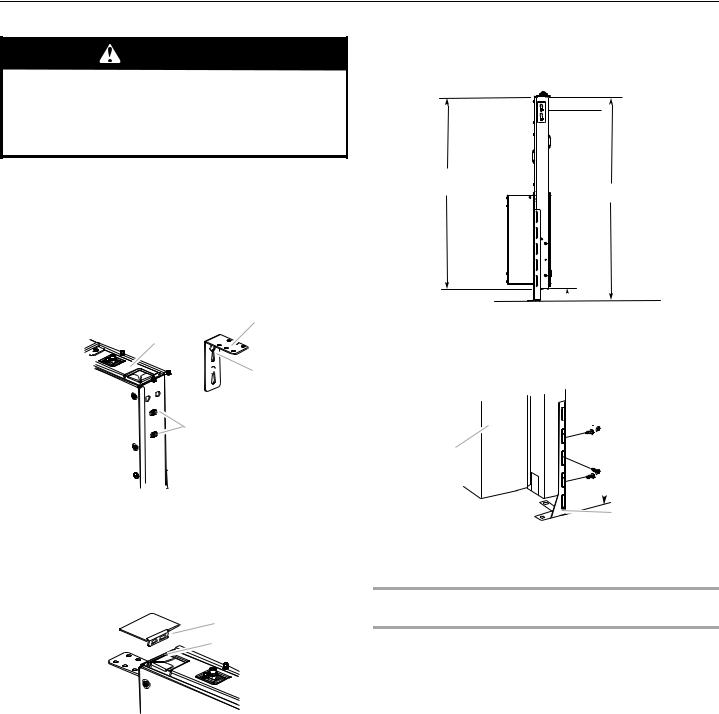
5.Attach the right and left end caps to the vent box. Place the tab into the mounting slot at each end of the downdraft vent as shown and push down to lock into place.
A
B
A.End cap tab
B.Mounting slot
6.Measure distance “X” from the cabinet floor to the top of the countertop. Subtract 28¹⁄ " from distance “X” to determine dimension “Y” (X - 28¹⁄ = Y).
Top of countertop
Downdraft vent
28¹⁄"
(73 cm)
“X”
 “Y”
“Y”
Cabinet floor
7.Attach the support legs to the side of the vent box with
4 - 4 x 8 mm screws in each support leg. Adjust to dimension “Y” from the bottom of the vent box to the bottom of the support legs. Tighten screws.


 C
C
A
 Dim. “Y”
 B
B
A.Motor box
B.Support leg
C.4 x 8 mm screws (4)
Determine Which Vent Direction Is Best for Your Installation
When installed in a cabinet, vent system can exhaust through the bottom, right or left of the cabinet.
NOTE: When using the 6" (15.2 cm) vent transition (supplied) for 6" round venting, only left or right venting is recommended.
11
Bottom Venting:
NOTE: If installing the vent damper in the down position, a wall or roof cap with a damper at the exit end of the vent system is required.
■Downdraft vent is shipped with blower in down venting position so no modification is required.
■If rear mounting of the blower motor is not required, go to the “Complete Installation (Interior-Mounted Motor)” section.
■To mount the blower motor to the rear side of the vent box, go to the “Rear Mounting - Blower Motor” section.
Left or Right Venting:
1.Using two or more people, place the downdraft vent system on its back.
2.Remove the 4 screws from the cover plate mounted to the face of the motor box and set them aside.
A
B
C 


D

A.Cover plate
B.Cover plate screws (4)
C.Cover plate keyhole slot shoulder screws (4)
G
F
E
D.Motor mounting screws (4) E. Vent cover plate
F. Motor box
G.Vent cover screws (3)
3.Slide the cover plate up and slip it over the keyhole slot shoulder screws. Set the cover aside.
4.Remove 4 screws from the bottom of the motor box that hold the motor assembly to the motor box.
NOTE: Disconnect the electrical wiring connection from motor if needed.
5.Remove 3 screws and the vent cover plate from the left or right side of the motor box for the venting direction to be used.
6.Rotate the blower motor assembly 90 degrees to the left or right side to the chosen venting direction and secure to the blower box with motor mounting screws previously removed. Do not twist or bind the wires.
7.Install the vent cover plate over the rectangular opening in the bottom of the motor box and secure with vent cover screws.
NOTE: Reinstall the electrical wiring connection to motor if removed.
8.Reinstall the cover plate to the face of the motor box and secure with 4 cover plate screws previously removed.
9.For mounting the blower motor to the back of the vent box, go to the “Rear Mounting - Blower Motor” section. Otherwise, go to the “Complete Installation (Interior-Mounted Motor)” section.
RearMounting—BlowerMotor
NOTE: Optional blower motor rear mounting position (opposite side) for island cabinet locations. The blower motor box assembly can be moved to the opposite side (rear) of the vent box.
1.Remove 7 screws from the mounting flanges of the blower motor box.
Front View
|
A |
A |
A |
|
|
C |
B |
A.Screws (7)
B.Keyhole slot shoulder screws (2)
C.Blower motor box
2.Lift blower motor box off the shoulder screws in the keyhole slots. Disconnect wire connection from blower motor and set blower motor box aside.
3.Remove 6 screws from the mounting flange of the ¹⁄ " (6.4 mm) deep cover.
Rear View
C |
A |
|
B |
A.Screws (6)
B.Keyhole slot shoulder screws (2)
C.¹⁄" (6.4 mm) deep cover
4.Lift the ¹⁄ " (6.4 mm) deep cover off the shoulder screws in the keyhole slots and set the cover aside.
12
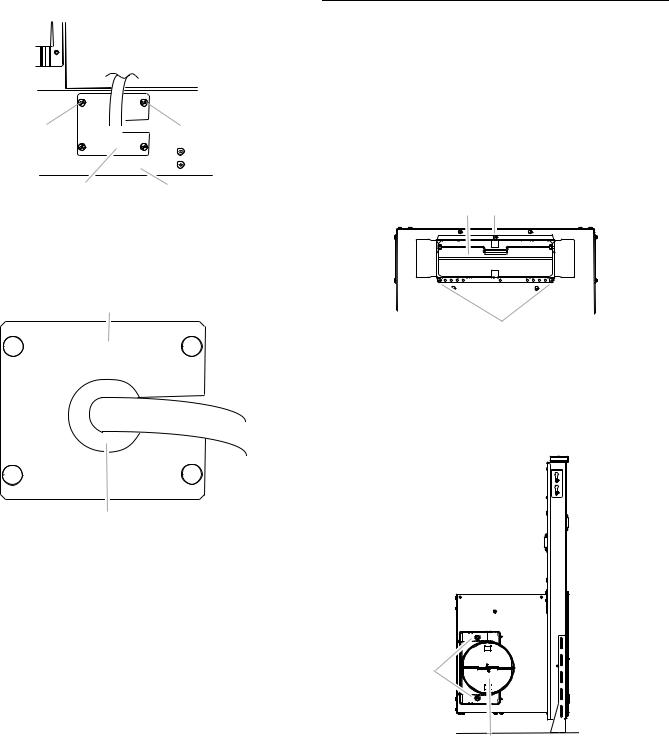
5. Remove the screws from the wire mounting plate.
A 

 A
A
B C
A.Screws
B.Wire mounting plate
C.Blower motor box
6.Hold the wire mounting plate and push the grommet out of the mounting plate.
A
B
A.Wire mounting plate
B.Grommet
7.Slide the wire assembly through the slot in the wire mounting plate to remove it.
8.Place the wire assembly through the opening to the opposite side of the vent box.
9.Reassemble the wire assembly and grommet to the wire mounting plate
10.Install the wire mounting plate to the vent box using the 4 screws previously removed.
11.Place the blower motor box assembly with the keyhole slots over the 2 shoulder screws on the rear of the vent box and reconnect the wire connection to the blower motor.
12.Mount the blower motor box to the vent box and secure using the 6 screws previously removed.
13.Mount the 4³⁄ " (12.0 cm) cover box (supplied) to the front of the vent box. Place the keyhole slots over the 2 shoulder screws, align the mounting holes, and secure the cover box to vent box using the 6 screws previously removed from the ¹⁄ " (6.4 mm) deep cover.
14.Go to the “Complete Installation (Interior-Mounted Motor)” section.
CompleteInstallation
(Interior-MountedMotor)
NOTE: The downdraft vent system is supplied with a 3¹⁄ " x 10" (8.3 x 25.4 cm) back draft damper and a 6" (15.2 cm) round vent transition with damper. Refer to “3¹⁄ " x 10" (8.3 x 25.4 cm) back draft damper” or “6" (15.2 cm) round vent transition with damper,” depending upon the type of venting you are using.
3¹⁄" x 10" (8.3 x 25.4 cm) Back Draft Damper
1.Attach the 3¼" x 10" (8.3 x 25.4 cm) back draft damper to the vent opening in the blower motor box, using three 3.5 x
9.5 mm screws.
B A
A
A.3.5 x 9.5 mm screws
B.3¼" x 10" (8.3 x 25.4 cm) back draft damper
6" (15.2 cm) Round Vent Transition with Damper
1.Attach the 6" (15.2 cm) round vent transition to vent opening (left or right side venting only is recommended), using two 3.5 x 9.5 mm screws.
A |
B
A.3.5 x 9.5 mm screws
B.6" (15.2 cm) round vent transition with damper
13
2. Remove 4 screws attaching the terminal box cover.
A |
A.Terminal box cover
3.Determine which direction (front or rear) the home power supply cable will enter the terminal box. Remove the appropriate knockout from the front or rear panel and install a ¹⁄" (12.7 mm) UL listed or CSA approved conduit connector.
4.Using 2 or more people, insert the downdraft vent into the countertop cutout. Position downdraft vent so it is centered in the cutout with the rear flange over the edge of the cutout and the rear of the vent box against the edge of the cutout.
A
5.Drill 2 pilot holes through each of the undercounter mounting brackets into the underside of the countertop. Using 2 screws (not provided) of the appropriate length, mount the brackets to the countertop.
IMPORTANT: Select a screw length that will not allow the screws to go through the countertop when tightened.
B
 C
C
A
A.Screws
B.Backsplash
C.Countertop
6.Check that the downdraft vent is level vertically. Loosen the lower support legs screws and position the legs against the cabinet floor.
7.Fasten the lower support legs to the cabinet floor with screws (not provided).
G 


 B
B
C
D
A
A. Screw (not provided)
8. Tighten the lower support legs screws.
|
E |
F |
|
A. Rear flange of downdraft vent |
D. Cabinet back |
B. Edge of cutout in countertop |
E. Lower support leg |
C. Rear of downdraft vent |
F. Cabinet floor |
|
G. Countertop |
14
MakeElectricalConnections
WARNING
Hazard
Disconnect power before servicing.
Replace all parts and panels before operating.
Failure to do so can result in death or electrical shock.
1.Disconnect power.
2.Feed the power supply cable through the conduit connector and into the terminal box.
WARNING
Hazard
Electrically ground blower
Connect ground wire to green and yellow ground wire in terminal box.
Failure to do so can result in death or electrical shock.
3.Connect the green (or green/yellow) ground wire to the green or yellow/green ground wire using UL listed wire connectors. Tighten the screw on the conduit connector.
4.Connect the 2 white wires together using UL listed wire connectors.
F C
D
E
 B
B
|
A |
A. Green or green and yellow |
D. Black wires |
ground wire |
E. UL listed or CSA approved |
B. White wires |
conduit connector |
C. UL listed wire connectors |
F. Downdraft vent wiring |
5.Connect the 2 black wires together using UL listed wire connectors.
6.Replace the terminal box cover and secure with screw.
7.Reconnect power.
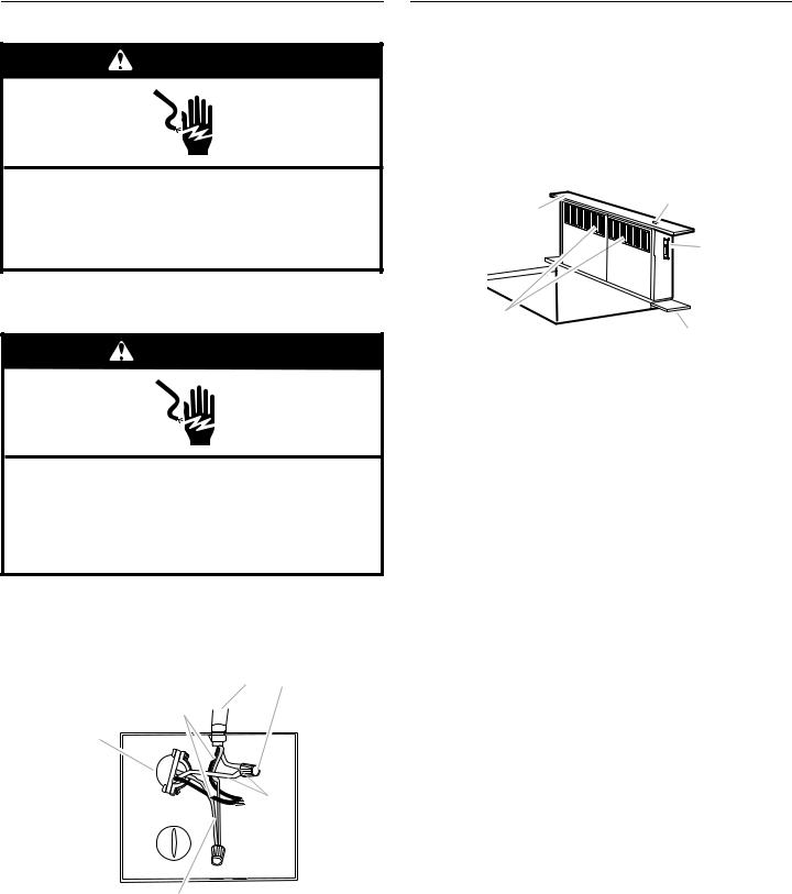
CheckOperation
1.Push and hold the button on the top of the downdraft vent for a few seconds. The retractable section of the downdraft vent will rise, and the blower will start. Position the top trim over the retractable section and snap trim into place.
Trim kits for matching your cooktop color are available from your dealer.
For information on ordering, see the “Assistance or Service” section.
A |
B |
|
|
|
C |
E |
D |
|
|
A. Top trim |
D. End cap |
B. ON/OFF button |
E. Filters |
C.Blower control slider
2.Slide the control slider on the side of vent to check the operation and speed of the blower.
3.If the blower does not operate:
■Check that filter or filters are pressed in as far as they will go.
■Check that the circuit breaker has not tripped or a household fuse blown.
4.Connect vent system to blower. Vent system must end with a wall or roof cap. Use clamps or duct tape to seal all joints.
5.Install cooktop according to manufacturer’s instructions. Check that rear of cooktop overlaps edge of retractable downdraft vent by ³⁄" (9.5 mm). See “Countertop Cutout Dimensions” in the “Location Requirements” section.
NOTE: To get the most efficient use from your new retractable downdraft vent, read the “Vent System Use” section.
15
INSTALLATION INSTRUCTIONS EXTERIOR-MOUNTED VENT MOTOR
CAUTION: To reduce the risk of fire and electrical shock, install the downdraft only with remote blower systems that are sold by Whirlpool Corporation. Model numbers UXI0600DYS (600 cfm) and UXI01200DYS (1200 cfm).
NOTE: Exterior-mounted vent motor installations require an approved in-line blower motor system. Model numbers UXI0600DYS (600 cfm) and UXI1200DYS (1200 cfm) are available from your dealer or authorized parts supplier. See “Blower motor system” in the “Accessories” section.
VentingMethods
Determine which venting method is best for your application. Vent system can terminate through the wall or roof. A wall cap or roof cap is required.
NOTES:
■Venting through a concrete slab is not recommended.
■The in-line blower motor system must be placed in an enclosed area and can be located in a utility room, basement, crawl space or attic. Observe all governing codes and ordinances.
■10" (25.4 cm) round vent duct is required for connections to the retractable downdraft vent system outlet cover and the in-line blower motor inlet and outlet covers. 10" (25.4 cm) round vent duct is recommended for the retractable downdraft vent system with in-line blower motor system. Transitioning to different size ducting will reduce the efficiency of the retractable downdraft vent system.
Island Location—Front |
Island Location—Rear Vent |
Vent |
|
To attic installed in-line blower motor system
To basement, crawlspace or utility room installed in-line blower motor system
To attic installed in-line blower motor system
To basement, crawlspace or utility room installed in-line blower motor system
Built-In Cabinet Locations
To attic installed in-line blower motor system
To basement, crawlspace or utility room installed in-line blower motor system
Calculating Vent System Length
It is recommended that you use round vent instead of rectangular vent, especially if elbows are required. If rectangular vent is required, it should be transitioned to 10" (25.4 cm) round vent as soon as possible.
Maximum Length of Vent System
Vent |
Length |
10" (25.4 cm) round |
60 ft (18.3 m) |
|
|
To calculate the length of the system you need, add the equivalent feet (meters) for each vent piece used in the system.
Vent Piece |
10" (25.4 cm) Round |
45° elbow |
2.5 ft |
|
(0.8 m) |
|
|
90° elbow |
5.0 ft |
|
(1.5 m) |
The maximum equivalent vent lengths of 10" (25.4 cm) round vents - 60 ft (18.3 m).
2 - 90° elbows |
= 10.0 ft (3 m) |
10 ft (3 m) straight |
= 10.0 ft (3 m) |
|
|
Length of 10" (25.4 cm) |
= 20 ft (6 m) |
system |
|
NOTE: The exterior-mounted vent motor requires a separate wiring cable that should be installed at the same time the vent work is installed.
16
InstallVentSystem
WARNING
Excessive Weight Hazard
Use two or more people to move and install downdraft vent.
Failure to do so can result in back or other injury.
1.Place cardboard or similar material on top of a flat surface where you can easily assemble the downdraft vent system.
2.Remove parts packages, downdraft vent and blower box from the carton.
3.Remove all shipping materials, tape and film from the downdraft vent and blower box.
4.Install the right and left undercounter mounting brackets to the vent box. Slide the keyhole slots over the guide tabs and push the brackets up to set them in place.
B
A


 C
C
D
A.Vent box
B.Undercounter mounting bracket
C.Keyhole slots
D.Guide tabs
5.Attach the left and right side end caps to the downdraft vent. Place the end cap upon the overcounter support, slide the tab into the slot and snap into place over the plastic tabs.
A
B
A.End cap tab
B.Mounting slot
6.Measure distance “X” from the cabinet floor to the top of the countertop. Subtract 28¹⁄ " from distance “X” to determine dimension “Y” (X - 28¹⁄ " = Y).
Top of countertop
Downdraft vent
28¹⁄"
(73 cm)
“X“
 “Y“
“Y“
Cabinet floor
7.Attach the support legs to the side of the vent box with
4 - 4 x 8 mm screws in each support leg. Adjust to dimension “Y” from the bottom of the vent box to the bottom of the support legs. Tighten screws.


 C
C
A
 Dim. “Y”
B
A.Motor box
B.Support leg
C.4 x 8 mm screws (4)
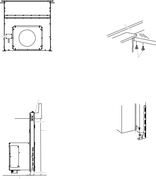
Determine Which Vent Direction Is Best for Your Installation
When installed in a cabinet the vent system can exhaust through the front or rear of the vent box. The downdraft vent is shipped with a 10" diameter vent collar plate.
Front or Rear Venting:
1.Using two or more people, place the downdraft vent system on the opposite side for venting.
2.Remove the 4 screws from the cover plate mounted to the face of the motor box and set them aside.
3.Slide the cover plate up and slip it over the keyhold slot shoulder screws. Set the cover aside.
4.Install the 10" diameter vent collar plate to the vent box where the cover plate was removed in the previous step. Secure using the 4 screws from the cover plate.
5.Go to the “Complete Installation (Exterior-Mounted Motor)” section.
17
 Loading...