


 Loading...
30" AND 36" (76.2 AND 91.4 CM) RANGE HOOD
Installation Instructions and Use & Care Guide
HOTTE D’ASPIRATION DE 30" ET 36" (76,2 ET 91,4 CM)
Instructions d’installation et Guide d’utilisation et d’entretien
Table of Contents/Table des matières............................................................................. |
2 |
IMPORTANT: READ AND SAVE THESE INSTRUCTIONS.
FOR RESIDENTIAL USE ONLY.
IMPORTANT : LIRE ET CONSERVER CES INSTRUCTIONS.
POUR UTILISATION RÉSIDENTIELLE UNIQUEMENT.
LIB0131212/W11088979A

TABLE OF CONTENTS |
|
RANGE HOOD SAFETY.................................................................. |
2 |
INSTALLATION REQUIREMENTS................................................. |
4 |
Tools and Parts............................................................................. |
4 |
Location Requirements................................................................. |
4 |
Venting Requirements................................................................... |
5 |
Electrical Requirements................................................................ |
7 |
INSTALLATION INSTRUCTIONS................................................... |
8 |
Prepare Location........................................................................... |
8 |
Complete Preparation................................................................. |
10 |
Install Range Hood..................................................................... |
12 |
Connect the Vent System........................................................... |
13 |
Complete Installation.................................................................. |
13 |
RANGE HOOD USE...................................................................... |
14 |
Range Hood Controls................................................................. |
14 |
RANGE HOOD CARE.................................................................... |
15 |
Cleaning...................................................................................... |
15 |
WIRING DIAGRAM........................................................................ |
16 |
ASSISTANCE OR SERVICE.......................................................... |
17 |
In the U.S.A................................................................................. |
17 |
In Canada.................................................................................... |
17 |
Accessories................................................................................. |
17 |
WARRANTY................................................................................... |
18 |
TABLE DES MATIÈRES |
|
SÉCURITÉ DE LA HOTTE DE CUISINIÈRE................................ |
19 |
EXIGENCES D’INSTALLATION.................................................... |
21 |
Outils et pièces........................................................................... |
21 |
Exigences d’emplacement......................................................... |
21 |
Exigences concernant l’évacuation............................................ |
22 |
Spécifications électriques........................................................... |
24 |
INSTRUCTIONS D’INSTALLATION............................................. |
25 |
Préparation de l’emplacement................................................... |
25 |
Préparation terminée.................................................................. |
27 |
Installation de la hotte................................................................. |
29 |
Raccordement du conduit d’évacuation.................................... |
30 |
Fin de l’installation...................................................................... |
30 |
UTILISATION DE LA HOTTE........................................................ |
31 |
Commandes de la hotte............................................................. |
31 |
ENTRETIEN DE LA HOTTE.......................................................... |
32 |
Nettoyage.................................................................................... |
32 |
SCHÉMA DE CÂBLAGE............................................................... |
33 |
ASSISTANCE OU SERVICE.......................................................... |
34 |
Aux É.-U. .................................................................................... |
34 |
Au Canada.................................................................................. |
34 |
Accessoires................................................................................. |
34 |
GARANTIE LIMITÉE DES GROS APPAREILS MÉNAGERS |
|
WHIRLPOOL®................................................................................ |
35 |
RANGE HOOD SAFETY
2

State of California Proposition 65 Warnings:
WARNING: This product contains one or more chemicals known to the State of California to cause cancer.
WARNING: This product contains one or more chemicals known to the State of California to cause birth defects or other reproductive harm.
IMPORTANT SAFETY INSTRUCTIONS
WARNING: TO REDUCE THE RISK OF FIRE, ELECTRIC SHOCK, OR INJURY TO PERSONS, OBSERVE THE FOLLOWING:
■Use this unit only in the manner intended by the manufacturer. If you have questions, contact the manufacturer.
■Before servicing or cleaning the unit, switch power off at service panel and lock the service disconnecting means to prevent power from being switched on accidentally. When the service disconnecting means cannot be locked, securely fasten a prominent warning device, such as a tag, to the service panel.
■Installation work and electrical wiring must be done by qualified person(s) in accordance with all applicable codes and standards, including fire-rated construction.
■Do not operate any fan with a damaged cord or plug. Discard fan or return to an authorized service facility for examination and/or repair.
■Sufficient air is needed for proper combustion and exhausting of gases through the flue (chimney) of fuel burning equipment to prevent backdrafting. Follow the heating equipment manufacturer's guideline and safety standards such as those published by the National Fire Protection Association (NFPA), the American Society for Heating, Refrigeration and Air Conditioning Engineers (ASHRAE), and the local code authorities.
■When cutting or drilling into wall or ceiling; do not damage electrical wiring and other utilities.
■Ducted fans must always be vented outdoors.
CAUTION: For general ventilating use only. Do not use to exhaust hazardous or explosive materials and vapors.
CAUTION: To reduce risk of fire and to properly exhaust air, be sure to duct air outside - do not vent exhaust air into spaces within walls or ceilings, attics or into crawl spaces, or garages.
WARNING: TO REDUCE THE RISK OF FIRE, USE ONLY METAL DUCTWORK.
WARNING: TO REDUCE THE RISK OF A RANGE TOP GREASE FIRE:
■Never leave surface units unattended at high settings. Boilovers cause smoking and greasy spillovers that may ignite. Heat oils slowly on low or medium settings.
■Always turn hood ON when cooking at high heat or when flambeing food (i.e. Crepes Suzette, Cherries Jubilee, Peppercorn Beef Flambé).
■Clean ventilating fans frequently. Grease should not be allowed to accumulate on fan or filter.
■Use proper pan size. Always use cookware appropriate for the size of the surface element.
WARNING: TO REDUCE THE RISK OF INJURY TO PERSONS IN THE EVENT OF A RANGE TOP GREASE FIRE, OBSERVE THE FOLLOWING:a
■SMOTHER FLAMES with a close fitting lid, cookie sheet, or metal tray, then turn off the burner. BE CAREFUL TO PREVENT BURNS. If the flames do not go out immediately, EVACUATE AND CALL THE FIRE DEPARTMENT.
■NEVER PICK UP A FLAMING PAN - you may be burned.
■DO NOT USE WATER, including wet dishcloths or towels - a violent steam explosion will result.
■Use an extinguisher ONLY if:
–You know you have a class ABC extinguisher, and you already know how to operate it.
–The fire is small and contained in the area where it started.
–The fire department is being called.
–You can fight the fire with your back to an exit.
aBased on "Kitchen Fire Safety Tips" published by NFPA.
■ WARNING: To reduce the risk of fire or electrical shock, do not use this fan with any solid-state speed control device.
READ AND SAVE THESE INSTRUCTIONS
3

INSTALLATION REQUIREMENTS
Tools and Parts
Gather the required tools and parts before starting installation. Read and follow the instructions provided with any tools listed here.
Tools needed
■■ Level
■■ Drill with 11/4" (3.2 cm), 1/8" (3 mm), and 1/16" (1.6 mm) drill bits
■■ Pencil
■■ Wire stripper or utility knife ■■ Pliers
■■ Tape measure or ruler
■■ Caulking gun and weatherproof caulking compound ■■ Phillips screwdriver
■■ Flat-blade screwdriver ■■ Vent clamps
■■ Jigsaw or keyhole saw
■■ Metal snips
Parts needed
■■ 6" (15.2 cm) round metal vent system
■■ Vent clamps/duct tape as required
For non-vented (recirculating) installations, you will need:
■■ Recirculation Kit. See the “Assistance or Service” section to order.
For vented installations, you will need:
■■ 1 wall or roof cap
Parts supplied
Remove parts from packages. Check that all parts are included. ■■ Hood assembly with LED lights already installed (1)
■■ Hood insert assembly with blower/electronic box ■■ 4.5 x 13 mm truss-head wood screws (11)
■■ 4.2 x 8 mm screws (8) ■■ 4 x 15 mm screws (10) ■■ 3.5 x 9.5 T10 (2)
■■ Mounting brackets (4)
■■ TORX®† adapter screws T10® and T20® adapter (1) ■■ 6.4 x 18 mm washers (8)
■■ 4.2 x 12 mm plastic washers (8)
■■ 6" (15.2 cm) round damper (1)
Parts not supplied
Optional Accessories
For non-vented (Recirculating) installations:
1.Please see the "Assistance or Service" Section for the recirculation kit part number information.
Location Requirements
IMPORTANT: Observe all governing codes and ordinances.
Have a qualified technician install the range hood. It is the installer’s responsibility to comply with installation clearances specified on the model/serial rating plate. The model/serial rating plate is located inside the liner behind the filter on the left wall of the range hood.
Range hood location should be away from strong draft areas, such as windows, doors, and strong heating vents.
Cabinet opening dimensions that are shown must be used. Given dimensions provide minimum clearance. Consult your cooktop/range manufacturer installation instructions before making any cutouts.
This range hood is recommended for use with cooktops with a maximum total rating of 65,000 Btus or less.
Grounded electrical outlet is required. See the “Electrical Requirements” section.
The range hood is factory set for vented installations through the roof or wall. For non-vented (recirculating) installations see “Non-Vented (recirculating) Installation Through the Soffit/ Cabinet” in the “Prepare Location” section. Recirculation Kit is
available from your dealer or an authorized parts distributor. See the “Assistance or Service” section to order.
All openings in ceiling and wall where range hood will be installed must be sealed.
For Mobile Home Installations
The installation of this range hood must conform to the Manufactured Home Construction Safety Standards, Title 24 CFR, Part 328 (formerly the Federal Standard for Mobile Home Construction and Safety, title 24, HUD, Part 280) or when such standard is not applicable, the standard for Manufactured Home Installation 1982 (Manufactured Home Sites, Communities and Setups) ANSI A225.1/NFPA 501A, or latest edition, or with local codes.
†TORX®, T10®, and T20® are trademarks of Acument Intellectual Properties, Inc.
4

Product Dimensions
30" Model |
36" Model |
161/2"
(42 cm) |
|
|
6" |
|
|
|
|
|
|
|
|
|
(15.2 cm) |
|
111/2" |
|
|
|
|
(29.2 cm) |
|
|
|
|
23/8" |
|
|
|
|
(6 cm) |
|
|
|
|
|
|
A |
|
1" |
|
|
|
|
|
|
|
|
|
(2.5 cm) |
26" |
2915/16" |
|
|
103/4" |
(66 cm) |
(76 cm) |
|
|
|
|
|
|
1911/16" |
(27.2 cm) |
|
|
|
|
|
|
|
|
(50 cm) |
|
A.30" Cabinet inner dimensions MIN: 2715⁄32" (69.75 cm) MAX: 2813⁄64" (71.65 cm)
Cabinet Dimensions
A
B
C
 D
D
E
F
A.12" (30.5 cm) min. upper cabinet height
B.30" cabinet width: min. 27.4" max 28.5" 36" cabinet width: min. 33.9" max 34.5"
C.24" (61.0 cm) min. from electric cooking surface, 27" (68.6 cm) min. from gas cooking surface, 36" (91.4 cm) suggested max. bottom of cabinet to cooking surface
D.12" (30.5 cm) cabinet depth
E.15" (38.1 cm) min. clearance upper cabinet to countertop
F.36" (91.4 cm) base cabinet height
161/2"
(42 cm)
111/2" |
6" |
|
|
(15.2 cm) |
A |
||
(29.2 cm) |
|||
|
23/8" (6 cm)
1" (2.5 cm)
26" |
3515/16" |
103/4" |
(66 cm) |
(91.4 cm) |
|
|
(27.2 cm) |
|
|
|
1911/16"
(50 cm)
A.36" Cabinet inner dimensions MIN: 3315⁄32" (86.2 cm)
MAX: 3411⁄16" (88.1 cm)
IMPORTANT: Mount this hood so that the bottom edge above the cooking surface is at 27" (68.5 cm) minimum if a gas range is used, or at 24" (61 cm) if an electric range is used. The suggested maximum distance is 36" (91.4 cm). For household use, please read the installation manual for specific application. Check your cabinet dimensions prior to selecting your vent hood.
Venting Requirements
(vented models only)
■■ Vent system must terminate to the outside, except for nonvented (recirculating) installations.
■■ Do not terminate the vent system in an attic or other enclosed area.
■■ Do not use a 4" (10.2 cm) laundry-type wall cap.
■■ Use metal vent only. A rigid metal vent is recommended. ■■ Plastic or metal foil vent is not recommended.
■■ The length of the vent system and number of elbows should be kept to a minimum to provide efficient performance.
For the most efficient and quiet operation:
■■ Use no more than three 90° elbows.
■■ Make sure there is a minimum of 24" (61.0 cm) of straight vent between the elbows if more than one elbow is used.
■■ Do not install two elbows together.
■■ The vent system must have a damper.
■■ Use clamps to seal all joints in the vent system.
■■ Use caulking to seal exterior wall or roof opening around the cap.
■■ The size of the vent should be uniform.
5
Cold weather installations
An additional backdraft damper should be installed to minimize backward cold air flow and a thermal break should be installed to minimize conduction of outside temperatures as part of the vent system. The damper should be on the cold air side of the thermal break.
The break should be as close as possible to where the vent system enters the heated portion of the house.
Makeup air
Local building codes may require the use of makeup air systems when using ventilation systems with greater than specified CFM of air movement. The specified CFM varies from locale to locale. Consult your HVAC professional for specific requirements in your area.
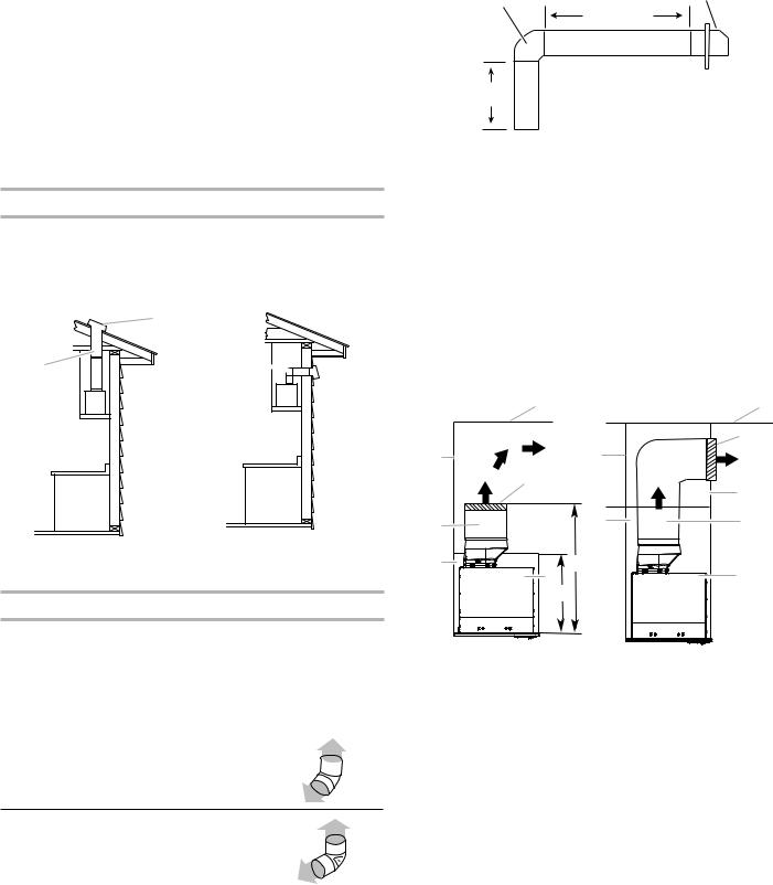
Venting Methods
This range hood is factory set for venting through the roof or through the wall.
The vent system needed for installation is not included. A 6" (15.2 cm) round vent system is recommended.
Roof Venting |
Wall Venting |
B
A A 

 B
B
A. 6" (15.2 cm) vent through |
A. 6" (15.2 cm) vent through |
the roof |
the wall |
B. Roof cap |
B. Wall cap |
Calculate Vent System Length
The recommended vent system is 6" (15.2 cm) round vent with a maximum length of 35 ft (10.7 m). For the best performance, use no more than three 90° elbows.
To calculate the length of the system, add the equivalent feet (meters) for each of the vent pieces used in the system.
Vent Piece |
6" (15.2 cm) |
|
|
|
|
45° elbow |
2.5 ft |
|
(0.8 m) |
||
|
Example vent system: 6" (15.2 cm)
Wall cap
90˚ elbow
6 ft (1.8 m)
3 ft
(0.93 m)
Maximum Length |
= 35 ft (10.7 m) |
|
|
|
|
1 |
- 90° elbow |
= 5 ft (1.5 m) |
1 |
- wall cap |
= 0 ft (0 m) |
9 ft (2.8 m) straight |
= 9 ft (2.8 m) |
|
|
|
|
System length |
= 14 ft (4.3 m) |
|
Non-Vented (recirculating) Installations Through the Soffit/Cabinet
If it is not possible to vent cooking fumes and vapors to the outside, the range hood can be used in the non-vented
(recirculating) version, using a charcoal filter. Charcoal Filter Kit is available from the dealer or an authorized parts distributor. See the “Assistance or Service” section to order.
Through Cabinet |
Through Soffit |
A |
A |
|
|
B |
G |
G |
|
B |
|
|
|
|
C |
D |
F |
D |
F |
I |
E |
E |
|
|
|
H |
|
A. Ceiling |
F. |
Cabinet |
B. Vent cover |
G. Wall |
|
C. Soffit |
H. 12" (30.5 cm) min. cabinet |
|
D. 6" (15.2 cm) vent |
|
height |
E. Range hood |
I. |
17" (43.2 cm) min. vent cover |
|
|
height |
NOTE: 12" (30.5 cm) high cabinets without a soffit may allow the 6" (15.2 cm) vent and vent cover to be seen.
90° elbow |
5.0 ft |
|
(1.5 m) |
||
|
||
|
|
6

Electrical Requirements
 WARNING
Electrical Shock Hazard Plug into a grounded 3 prong outlet. Do not remove ground prong.
Do not use an adapter.
Do not use an extension cord.
Failure to follow these instructions can result in death, fire, or electrical shock.
IMPORTANT: The range hood must be electrically grounded in accordance with local codes and ordinances, or in the absence of local codes, with the National Electrical Code, ANSI/NFPA 70 (latest edition) or Canadian Electrical Code, CSA C22.1 No. 0-M91 (latest edition).
If codes permit and a separate ground wire is used, it is recommended that a qualified electrical installer determine that the ground path is adequate.
A copy of the above code standards can be obtained from:
National Fire Protection Association
1 Batterymarch Park
Quincy, MA 02169-7471
CSA International
8501 East Pleasant Valley Road
Cleveland, Ohio 44131-5575
■■ A 120 volt, 60 Hz, AC only, 15or 20-amp, fused electrical circuit is required. A time-delay fuse or circuit breaker is also recommended. It is recommended that a separate circuit serving only this range hood be provided.
■■ This range hood is equipped with a power supply cord having a 3 prong grounding plug.
■■ To minimize possible shock hazard, the cord must be plugged into a mating, 3 prong, grounding-type outlet, grounded in accordance with local codes and ordinances. If a mating outlet is not available, it is the personal responsibility and obligation of the customer to have the properly grounded outlet installed by a qualified electrician.
■■ The grounded 3 prong outlet is to be located inside the cabinet above the range hood at a maximum distance of 337/16" (85.0 cm) from where the power cord exits the hood. The grounded 3 prong outlet must be accessible after installation of the range hood. See illustration.
337/16"
(85 cm)
GROUNDING INSTRUCTIONS
■ For a grounded, cord-connected range hood:
This range hood must be grounded. In the event of an electrical short circuit, grounding reduces the risk of electric shock by providing an escape wire for the electric current. This range hood is equipped with a cord having a grounding wire with a grounding plug. The plug must be plugged into an outlet that is properly installed and grounded.
WARNING: Improper grounding can result in a risk of electric shock.
Consult a qualified electrician if the grounding instructions are not completely understood, or if doubt exists as to whether the range hood is properly grounded.
Do not use an extension cord. If the power supply cord is too short, have a qualified electrician install an outlet near the range hood.
SAVE THESE INSTRUCTIONS
7

INSTALLATION INSTRUCTIONS
Prepare Location
■■ It is recommended that the vent system be installed before the range hood is installed.
■■ Before making cutouts, make sure there is proper clearance within the ceiling or wall for vent fittings.
■■ Making the cutout to the bottom of the cabinet may be easier to do prior to mounting the cabinet to the wall.
1.Disconnect power.
2.Determine which venting method to use: roof, wall, or non-vented.
3.Select a flat surface for assembling the range hood. Place covering over that surface.
 WARNING
Excessive Weight Hazard
Use two or more people to move and install range hood.
Failure to do so can result in back or other injury.
4.Using two or more people, lift range hood onto covered surface.
Range Hood Cabinet Cutout
1.Use a saber saw or keyhole saw to cut out the cabinet bottom inside the cabinet frame.
NOTE: Frameless type cabinets require 3/4" (19 mm) front lip in the cabinet bottom. A 3/4" (19 mm) thick filler strip (not supplied) may be required for some types of cabinets (see Step 3 in the “Install Range Hood” section).
E D
|
|
|
|
|
|
A |
|
|
|
|
|
|
|
|
|
|
C |
||
|
|
|
|
|
|
|
|
|
|
|
|
|
|
|
|
|
|
|
|
B
A.Bottom of cabinet cutout
B.Bottom must be cut flush to the inside walls of the cabinet
C.107⁄8" (27.6 cm) min. from the inside of the cabinet front face
D.Min. 3/8 (9.5 mm), max 3/4" (19 mm) thick front face required for cabinet bottom
E.Front of cabinet
2.Complete cabinet preparation following the instructions for your type of venting. Determine venting cutout locations and cut out vent openings in the cabinets, walls, and/or soffit.
Venting Outside Through the Roof
1.Measure and mark the lines as the cutout chart shown. Use a saber saw or keyhole saw to cut an opening through the top of the cabinet and the roof for the vent.
|
Cutout chart |
|
|
Cabinet Height |
Hole Shape and Size |
|
|
12" (30.5 cm) |
A 817⁄64" wide x 6¼" deep |
|
(21 cm x 15.9 cm) rectangular |
|
opening in the cabinet top is |
|
required for damper transition |
|
clearance. |
|
A |
|
B* |
C |
D |
|
E
A. |
Cutout |
D. |
611⁄16” (17 cm) from cabinet’s |
B. |
817⁄64" (21 cm) |
|
front wall inner side |
C. 6¼" (15.9 cm) |
E. Centerline |
||
8
Cabinet Height |
Hole Shape and Size |
|
15" (38.1 cm) |
A 6¼" (15.9 cm) diameter round |
|
|
opening is required. |
|
|
A |
|
|
B* |
C |
D
A. Cutout |
C. 71⁄2" (19 cm) centerline to |
B. Ø 6¼" (15.9 cm)* |
cabinet front |
|
D. Centerline |
Cabinet Height |
Hole Shape and Size |
|
|
18" (45.7 cm) or |
A 5¾" (14.6 cm) diameter round |
24" (61.0 cm) |
opening is required. |
For non-vented (recirculating) installations only, the range hood can be vented indoors through the top of the cabinet.
For non-vented (recirculating) installations, charcoal filters are necessary. See the “Range Hood Care” section for instructions on installing charcoal filters. The Recirculation Kit must be used. See the “Assistance or Service” section to order.
Venting Outside Through the Wall
1.Install transition on top of hood (if removed for shipping) with two 3.5 x 9.5 mm sheet metal screws.
B
A
A.Vent transition
B.3.5 x 9.5 mm screws
2.Assemble the vent duct that you will use over the
6" (15.2 cm) vent transition. Measure from the bottom of the range hood liner to the horizontal centerline of the vent opening (A).
B |
A |
C |
A.Measurement A
B.Horizontal centerline of vent opening
C.Range hood liner
3.Remove the vent duct from the range hood liner.
Transfer measurement A to the cabinet back wall. Measure from the underside of the cabinet.
4.Mark the cutout as shown. Use a saber saw or keyhole saw to cut a round opening through the top of the cabinet and the exterior wall for the vent.
 C
C
A
B 
A.Measurement A
B.Centerline
C.6¼" (15.9 cm) round cutout
9

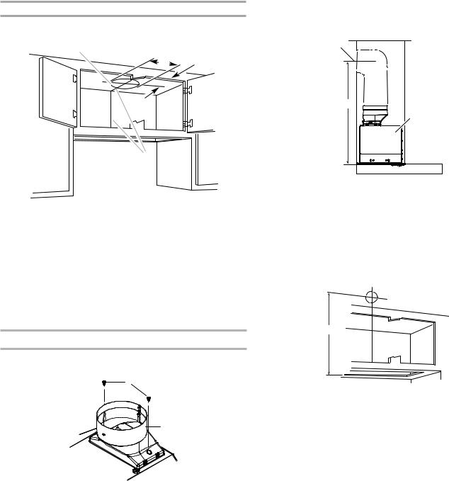
Non-Vented (recirculating) Installation through the Cabinet/Soffit
Through top of Cabinet:
Recirculating through the cabinet top wall
|
A |
|
G |
|
|
D |
|
|
F |
E |
I |
|
||
|
H |
|
|
|
A. Ceiling |
F. |
Cabinet |
B. Recirculating grid |
G. Wall |
|
C. Soffit |
H. 12" (30.5 cm) min. cabinet |
|
D. 6" (15.2 cm) round vent system |
|
height |
E. Range hood |
I. |
17" (43.2 cm) min. vent cover |
Through Soffit: |
|
height |
|
|
|
Recirculating through the soffit
|
A |
|
B |
G |
|
F |
D |
|
E |
A.Ceiling
B.Recirculating grid
C.Soffit
E.Range hood
F.Cabinet
G.Wall
D.6" (15.2 cm) round vent system
1.Measure and mark the centerline of the cabinet to the soffit above.
2.Measure from the bottom of the cabinet to the centerline of the where the vent will come through the soffit or cabinet top wall. Mark the location and use a saber saw or keyhole saw to cut a 5¾" (14.6 cm) hole for the vent cover.
A
A.Vent cover
B.Centerline
NOTE: For 12" (30.5 cm) high cabinets a 6¼" deep x 8" wide (14.6 cm x 20.3 cm) rectangular opening in the cabinet top is required for damper transition clearance.
3.Consider the cutout chart measures to make the openings on the cabinet.
NOTE: 12" (30.5 cm) high cabinets without a soffit may allow the 6" (15.2 cm) vent and vent cover to be seen.
Complete Preparation
Installation brackets configuration
To assemble the installation brackets, you must consider the cabinet's material thickness and your cabinet's width (30" [76.2 cm] or 36" [91.44 cm]).
1.Measure your cabinet material thickness, then locate the bracket’s installation holes, based on your cabinet thickness (see the chart below).
Cabinet material thickness
|
|
Bracket |
Cabinet |
|
|
5 |
marks |
Thickness |
|
|
1 |
3/8” |
||
4 |
3 |
|||
2 |
1/2” |
|||
2 |
1 |
|||
3 |
5/8” |
|||
|
|
|||
|
|
4 |
3/4” |
|
|
|
5 |
1” |
10
2.Orient the brackets depending on the width (30" or 36") of your cabinet as depicted in the images below, then secure them with three 4 x 15 mm screws on the selected thickness hole.
30" width cabinet |
36" width cabinet |
A |
A |
A.4 x 15 mm screws
3.Using the bracket as a template, mark four spots in each side of the cabinet to drill 1/8" (3 mm) pilot holes.
Bracket Orientation for 30" (76.2 cm) Cabinet
A 
D
B


C


A.30" (76.2 cm) cabinet
B.Screws - 4.5 x 13 mm (8)
C.Washers (optional)
D.Mounting bracket (4) (position for 30" [76.2 cm] cabinet)
Bracket Orientation for 36" (91.4 cm) Cabinet
D
B
A
A. Pilot holes
NOTE: Align the bracket with the front and the back side of the cabinet and ensure that the bottom of the bracket is installed tight against the bottom of the cabinet.
4.Attach a bracket using four 4.5 x 13 mm screws to each side of the cabinet, and tighten.
Additional washers in hardware package are supplied as spacers for cabinet walls thinner than 1/2" (13 mm).
C A
A.36" (91.4 cm) cabinet
B.Screws - 4.5 x 13 mm (8)
C.Washers (optional)
D.Mounting bracket (4) (position for 36" [91.4 cm] cabinet)
5.Install the vent system according to the method needed.
6.Use caulking to seal the exterior wall or roof opening.
11
Loading...