

KitchenAid KOSE900HBS00, KOSE900HSS00, KODE900HSS00, KODE900HBS00 Installation Guide
INSTALLATION INSTRUCTIONS 30" (76.2 CM) ELECTRIC SINGLE AND DOUBLE BUILT-IN OVEN
INSTRUCTIONS D’INSTALLATION DES FOURS ENCASTRÉS SIMPLE ET DOUBLE DE 30 PO (76,2 CM)
Table of Contents/Table des matières
BUILT-IN OVEN SAFETY................................................................. |
2 |
INSTALLATION REQUIREMENTS................................................. |
2 |
Tools and Parts............................................................................. |
2 |
Location Requirements................................................................. |
3 |
Electrical Requirements................................................................ |
6 |
INSTALLATION INSTRUCTIONS................................................... |
7 |
Prepare Built-In Oven................................................................... |
7 |
Remove Oven Door(s)................................................................... |
7 |
Replace Oven Door(s)................................................................... |
8 |
Positioning Oven Feet for Multiple Cabinet Cutout Heights........ |
8 |
Make Electrical Connection........................................................ |
13 |
Install Oven................................................................................. |
14 |
Complete Installation.................................................................. |
16 |
SÉCURITÉ DU FOUR ENCASTRÉ............................................... |
17 |
EXIGENCES D’INSTALLATION.................................................... |
17 |
Outils et pièces........................................................................... |
17 |
Exigences d’emplacement......................................................... |
18 |
Spécifications électriques........................................................... |
21 |
INSTRUCTIONS D’INSTALLATION............................................. |
22 |
Préparer le four encastré............................................................ |
22 |
Enlever la ou les portes du four.................................................. |
22 |
Réinstaller la ou les portes du four............................................. |
23 |
Positionner les pieds du four pour des ouvertures |
|
de découpe dans l’armoire......................................................... |
24 |
Raccordement électrique........................................................... |
28 |
Installer le four............................................................................. |
30 |
Terminer l’installation.................................................................. |
32 |
IMPORTANT:
Save for local electrical inspector's use.
IMPORTANT :
À conserver pour consultation par l'inspecteur local des installations électriques.
W11047061C
BUILT-IN OVEN SAFETY
Your safety and the safety of others are very important.
many important safety messages in this manual and on your appliance. Always read and obey all safety
safety alert symbol.
alerts you to potential hazards that can kill or hurt you and others.
messages will follow the safety alert symbol and either the word “DANGER” or “WARNING.”
mean:
 DANGER
  WARNING
You can be killed or seriously injured if you don't immediately follow instructions.
You can be killed or seriously injured if you don't follow instructions.
All safety messages will tell you what the potential hazard is, tell you how to reduce the chance of injury, and tell you what can happen if the instructions are not followed.
INSTALLATION REQUIREMENTS
Tools and Parts
Gather the required tools and parts before starting installation. Read and follow the instructions provided with any tools listed here.
Tools Needed
■■ Phillips screwdriver ■■ Measuring tape
■■ Hand or electric drill (for wall cabinet installations) ■■ 1" (2.5 cm) drill bit (for wall cabinet installations) ■■ Level
■■ Flat-blade screwdriver
Parts Needed
■■ UL Listed or CSA Approved conduit connector ■■ UL Listed wire connectors
■■ Warming Drawer Deflector Kit (for ovens installed above a warming drawer)
Order Part Number W10536339 for stainless steel 30" 76.2 cm) kit
Order Part Number W10727416 for black stainless steel 30" (76.2 cm) kit
To order, see the “Assistance or Service” section of the Use and Care Guide.
■■ Flush Installation Kit (for Single and Double installed at flush installation)
Order Part Number W10752683 for stainless steel 30" (76.2 cm) kit
Order Part Number W10752682 for black stainless steel 30" (76.2 cm) kit
To order, see the “Assistance or Service” section of the Use and Care Guide.
Parts Supplied
■■ #8-14 x 3/4" (1.9 cm) screws - single ovens (2), double ovens (4)
■■ #8-18 x 3/8" (9.5 mm) screws - bottom vent (2)
■■ #8-18 x 1/4" (6.4 mm) screws - bottom vent trim (4) ■■ #8-18 x 3/8" (9.5 mm) screws - double oven feet (4) ■■ Bottom vent
■■ Rear feet - double oven (2)
■■ Front feet - double oven (2)
Check local codes. Check existing electrical supply. See the “Electrical Requirements” section.
It is recommended that all electrical connections be made by a licensed, qualified electrical installer.
2
Location Requirements
IMPORTANT: Observe all governing codes and ordinances.
■■ Cabinet opening dimensions that are shown must be used. Given dimensions provide minimum clearance with oven.
■■ Recessed installation area must provide complete enclosure around the recessed portion of the oven.
■■ Grounded electrical supply is required. See the “Electrical Requirements” section.
■■ Electrical supply junction box should be located 3" (7.6 cm) maximum below the support surface when the oven is installed in a wall cabinet. A 1" (2.5 cm) minimum diameter hole should have been drilled in the right rear or left rear corner of the support surface to pass the appliance cable through to the junction box.
NOTE: For undercounter installation, it is recommended that the junction box be located in the adjacent right or left cabinet. If you are installing the junction box on rear wall behind oven, it is recommended that the junction box
be recessed and located in the upper center of the cabinet.
■■ Oven support surface must be solid, level, and flush with bottom of cabinet cutout.
■■ Floor must be able to support a single oven weight of 200 lbs (91 kg) for 30" (76.2 cm) models.
■■ Floor must be able to support a double oven weight of 330 lbs (150 kg) for 30" (76.2 cm) models.
IMPORTANT: To avoid damage to your cabinets, check with your builder or cabinet supplier to make sure that the materials used will not discolor, delaminate, or sustain other damage. This oven has been designed in accordance with the requirements of UL and CSA International and complies with the maximum allowable wood cabinet temperatures
of 194°F (90°C).
Undercounter Installation (with Cooktop Installed Above):
Ovens approved for this type of installation have an approval label located on the top of the oven. Refer to Cutout Dimensions for Ovens Installed Under Cooktop (separate sheet).
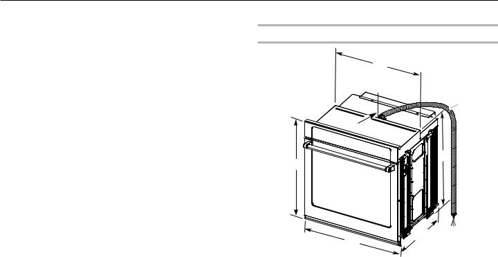
Product Dimensions - Single Ovens
B
G
 F
F
 C
C
A
E |
D |
|
30" (76.2 cm) models
A.283/4" (72.8 cm) max. overall height
B.281/2" (72.4 cm) max. recessed width
C.263/4" (67.9 cm) recessed height
D.231/4" (59.1 cm) max. recessed depth
E.30" (76.2 cm) overall width
F.12" (30.5 cm) from back of control panel to start of strain relief
G.48" (121.9 cm) flexible conduit length
3
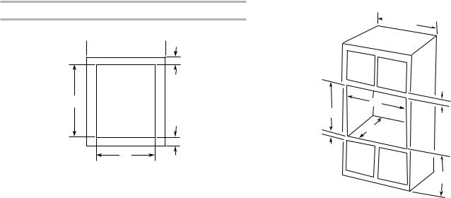
Cabinet Dimensions - Single Ovens
Single Oven Undercounter (Without Cooktop Installed Above)
 A
A  B
B
E
D |
C |
|
30" (76.2 cm) models
A.30" (76.2 cm) min. cabinet width
B.11/2" (3.8 cm) min. top of cutout to underside of countertop
C.51/4" (13.3 cm) bottom of cutout to floor
D.281/2" (72.4 cm) cutout width
E.28" (71.2 cm) min. cutout height
Single Ovens Installed in Cabinet
 A
A
B
D
F
G
E
C
30" (76.2 cm) models
A.30" (76.2 cm) min. cabinet width
B.1" (2.5 cm) top of cutout to bottom of upper cabinet door
C.32" (81.3 cm) bottom of cutout to floor
D.281/2" (72.4 cm) cutout width
E.11/2" (3.8 cm) min. bottom of cutout to top of cabinet door
F.28" (71.2 cm)* recommended cutout height
G.24" (60.7 cm) cutout depth
*NOTE: The cutout height can be between 2615/16" and 297/16" (68.4 cm and 74.8 cm) for single ovens.
4

Product Dimensions - Double Ovens
B
G
 F
F
A |
C |
E D
30" (76.2 cm) models
A.513/16" (130.0 cm) max. overall height
B.281/2" (72.4 cm) max. recessed width
C.4813/16" (124.0 cm) recessed height
D.231/4" (59.1 cm) max. recessed depth
E.30" (76.2 cm) overall width
F.12" (30.5 cm) from back of control panel to start of strain relief
G.66" (167.6 cm) flexible conduit length
Cabinet Dimensions - Double Ovens
Double Ovens Installed in Cabinet
 A
A 

B
 D
D
F
 G
G
E
C
30" (76.2 cm) models
A.30" (76.2 cm) min. cabinet width
B.1" (2.5 cm) top of cutout to bottom of upper cabinet door
C.143/4" (37.5 cm) bottom of cutout to floor is recommended. 4"-143/4" (10.2 cm-37.5 cm) bottom of cutout to floor is acceptable.
D.281/2" (72.4 cm) cutout width
E.11/2" (3.8 cm) min. bottom of cutout to top of cabinet door
F.501/4" (127.6 cm)* recommended cutout height
G.24" (60.7 cm) cutout depth
*NOTE: The cutout height can be between 487/8" and 523/16" (124.1 cm and 132.6 cm) for double ovens.
5
Electrical Requirements
If codes permit and a separate ground wire is used, it is recommended that a qualified electrical installer determine that the ground path and the wire gauge are in accordance with local codes.
Check with a qualified electrical installer if you are not sure the oven is properly grounded.
This oven must be connected to a grounded metal, permanent wiring system.
Be sure that the electrical connection and wire size are adequate and in conformance with the National Electrical Code, ANSI/NFPA 70 — latest edition or CSA Standards C22. 1-94, Canadian Electrical Code, Part 1 and C22.2 No. O-M91 — latest edition, and all local codes and ordinances.
A copy of the above code standards can be obtained from:
National Fire Protection Association
1 Batterymarch Park
Quincy, MA 02169-7471
CSA International
8501 East Pleasant Valley Road
Cleveland, OH 44131-5575
Electrical Connection
To properly install your oven, you must determine the type of electrical connection you will be using and follow the instructions provided for it here.
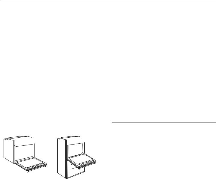
■■ Oven must be connected to the proper electrical voltage and frequency as specified on the model/serial/rating plate. The model/serial/rating plate is located under the control panel on single ovens and under the control panel on the upper oven cavity on double ovens. See the following illustrations.
 A
A  A
A
■■ Models rated from 7.3 to 9.6 kW at 240 volts (5.4 to 7.4 kW at 208 volts) require a separate 40-amp circuit. Models rated at 4.8 kW and below at 240 volts (3.6 kW and below at 208 volts) require a separate 20-amp circuit.
■■ A circuit breaker is recommended.
■■ Connect directly to the circuit breaker box (or fused disconnect) through flexible, armored, or nonmetallic sheathed, copper cable (with grounding wire). See the “Make Electrical Connection” section.
■■ Flexible conduit from the oven should be connected directly to the junction box.
■■ Fuse both sides of the line.
■■ Do not cut the conduit. The length of conduit provided is for serviceability of the oven.
■■ A UL Listed or CSA Approved conduit connector must be provided.
■■ If the house has aluminum wiring, follow the procedure below:
Connect the aluminum wiring using special connectors and/or tools designed and UL listed for joining copper to aluminum.
Follow the electrical connector manufacturer’s recommended procedure. Aluminum/copper connection must conform with local codes and industry accepted wiring practices.
Voltage |
Single |
Double |
|
|
|
240 VAC |
5.8 kW |
9.6 kW |
|
|
|
208 VAC |
4.4 kW |
7.7 kW |
|
|
|
Single Oven |
Double Oven |
A. Model/serial/rating plate |
A. Model/serial/rating plate |
6
 Loading...