

Kia Sportage 2000 User Manual
2OOO
SPORTAGE
ELECTRICAL TROU BLESHOOTI NG
AND VACUUM HOSE
Air Conditioner:
A/T Cear Selection lndicator...............
Electronic
Control Module......
Engine Coolant Temperature
Time and Alarm
ROUTING
MANUAL
CONTENTS
..... ...119
Bell\ Indrerl{)r................. ...
Fa\len
Conne,.tor Clarsrfrealron.......................
lgnition Key Warning, Fasten Belts Indicator, and Light
Waming. ......................
On
.........73
......2-13
..............73
CONTENTS
(Continued)
pr'rz
| ,ohr.
Sequential
r, nT nnHar
snPA't^mcrcr
\r^nt,ohr(
rruP,,E'i'i...............
Multiport Fuel
Injection
............110-3
..................
...........110-2
.......
............................
25
"81-4
I t0
HOW
TO
USE THIS
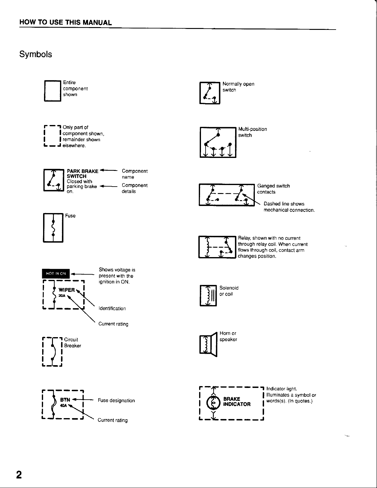
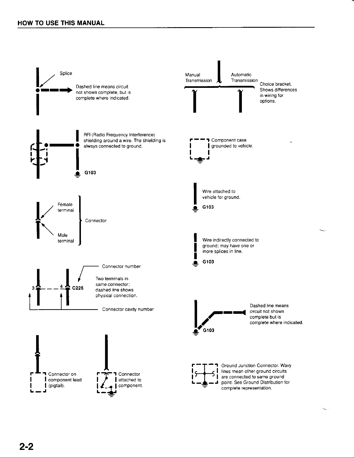
Symbols
MANUAL
nt'ifft"""
- .l
f
I lcomponent
| |
L - J
gart
Only
remainder
elsewhere
PARK
BRAKE
SWITCH
Closed with
parking
on,
Fuse
of
shown,
shown
brake
<-
+-
Component
name
Component
details
Normally
switch
'lt
open
Multi-position
sw[cn
',
G--7->.
Relay,
through relay
Jlows through
changes
Ganged switch
conlac$
Dashed
mechanical
shown wilh no
coil. When
coil, contact
position.
line shows
connection-
current
current
arm
Snows votlage rs
ignilion
in
ON.
ldentitication
\
Circuit
Breaker
Current.ating
Ij
il-";-i
L_(_:>i-
Fuse
designation
Currenl rating
Solenoid
or coil
HOrn
or
speaker
r-{F-----.1
Indicator
llluminates
words(s).
i6*** i
r_L_____.i
light.
a symbol
(ln
quotes.)
or
2
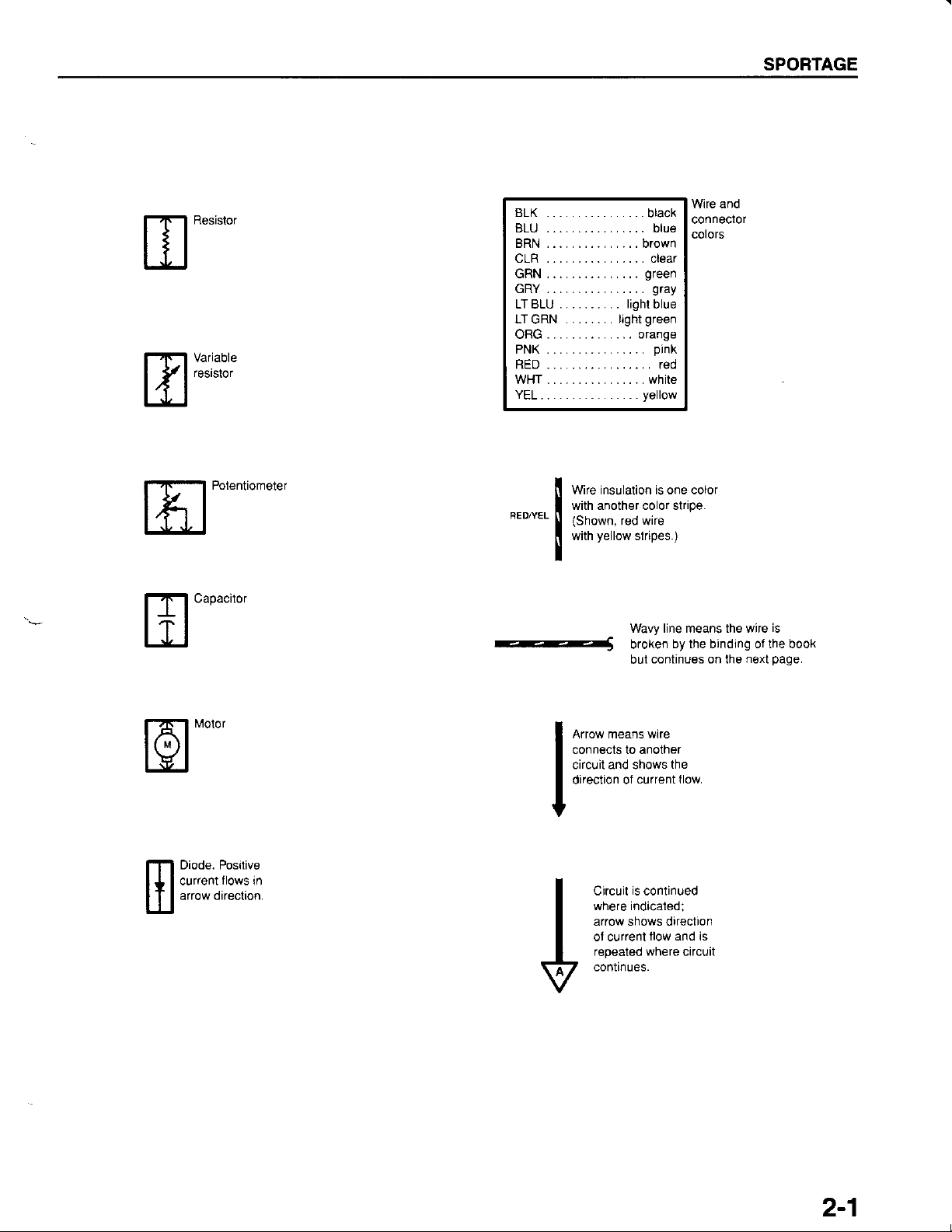
SPORTAGE
[flr1f3:
Polentiometer
BLK ...... ....... ...
BLU ................ blue
BRN ............... brown
uLH ... _...... _.. _ Ctear
GRN...............
GRY ................
.......... lightblue
LTBLU
LTGRN . . . . . . . . light
ORG..............
PNK ................
RED ................. red
WHT................ white
YEL................
wire rnsularion rs one cotor
ll
with another color stripe.
I
"'"'""
orange
yellow
I fiflJ;;0,il[.,
I
-----S
Wavy line means the wire
broken
but
Wire and
black
conneclor
colors
green
gray
green
pink
by the binding of the book
continues on the
next
is
page.
fol"'"'
Diode. Posilive
flows
current
arrow direction.
in
A.,o* r"un. *',"
I
connects to anolher
I
circuit and shows
I
direclion of
I
current flow.
I
is
Circuit
where indicaled;
arrow shows direction
ol current
repeated where
continues.
the
continued
llow and is
circuit
2-1
HOW TO USE
THIS MANUAL
V-:
Dashed line means
not shown complete, bul is
complete where indicaled.
I
(Badio
RFI
I
-a
vi:x:",
f\
"""
shielding around a wire. The Shielding
always connecled to
I
G103
!
Connector
circuit
Frequency lntederence)
ground.
Manual
Transmission
is
F--
1 Componeni
| |
tl
L-J
I
3
I
I
I
!
grounded
Wire attached to
vehicle Jor
G103
wire indirectly connected lo
ground;
more
G103
ground.
may have
in line.
splices
Automalic
Transmission
case
vehicle.
to
or
one
Choice bracket.
Shows ditt€rences
in wiring lor
opiions.
,|--if"'r"{'l[$il,
I
| ^-t- comorere our''s
laa
G103
l-
rl
Ground J0nction
.f..onn".,o.on
| component
|
| |
L-J
(pigtait).
2-2
lead
tlr"onn"oo,
I
l{_4
L-i:r
lattachedlo
I
lcomponent.
i*j
lines mean
are connected
point.
complele representation.
oashed hne reans
comPlele
Conneclor.
ground
olher
to same
Ground Distribution
See
where
Wavy
circuits
ground
indicated
ior
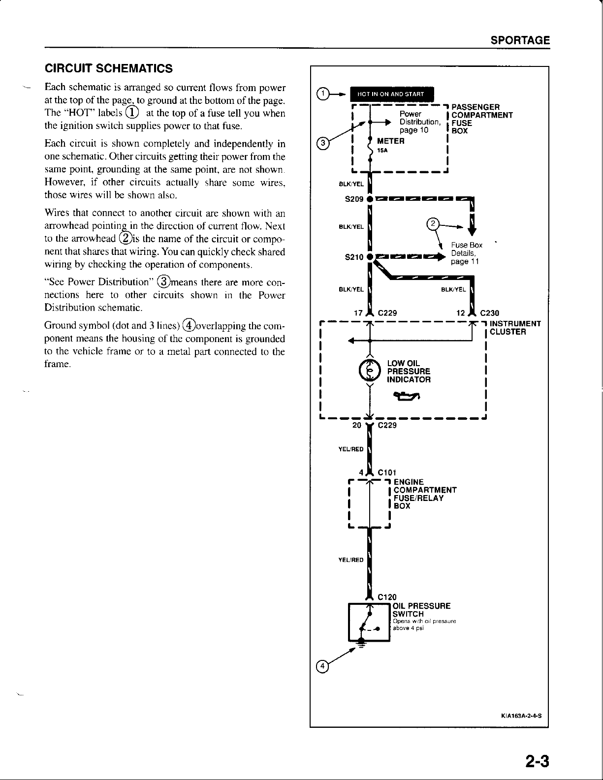
CIRCUIT SCHEMATICS
Each
schematic is ananged so
at the top of the
"HOT"
The
the ignition switch supplies
pageLo ground
(!
labels
at rhe
current flows from
lop ol a fuse tell
power
ar rhe bottom of
to that fuse.
the
you
SPORTAGE
power
page.
when
Each circuit is shown
one schematic.
point, grounding
same
However, if other
those wires will
Wires
that connect to another
anowhead
to the arrowhead
nent
that shares that wiring. You
wiring by checking the
"See
Power Distribution"
nections here to other
Distribution schematic.
Ground symbol
ponent
to the vehicle frame
trame.
means the housing
Other circuits
circuits actuallv
be shown also.
pointinqrn
(!)is
(dot
and 3 lines)
the
the name
or to a metal
completely and independently
getting
at the
same
circuit are
direction of current
of the circuit or compo-
can
operation of components.
@rn"unr
circuits shown in
@overlapping
of the component is
power
their
point,
share some wires.
quickly
there are more
part
connected to the
from the
are not shown.
shown
with
flow. Next
check
shared
the Power
the
grounded
con-
com-
in
an
".,,..
X-----
I
s210 4
ATKYEL
I
aa4>
lt
r
Fuse 8ox
Detal:'j
1 INSTRUMENT
CLUSTER
___J__:
"-:x",.,
i
llsg'-'*"
*:.t'
!
",,.
PRESSURE
OIL
swtTcH
Opens wth orlpressure
KrA163A-2{.S
2-3
HOW TO USE THIS MANUAL
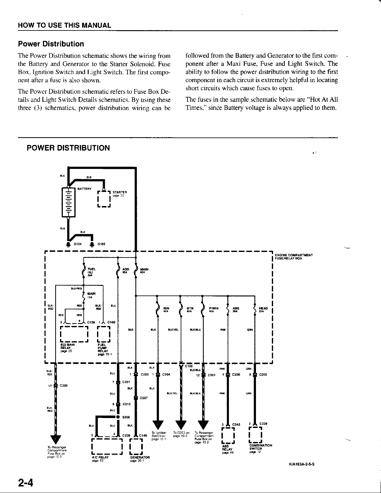
Power Distribution
Power
The
the Battery and
Box, Ignition
nent after a
The Power Distribution schematic
tails and Light Switch Details schematics.
three
Distribution schematic shows
Generator to the Starter Solenoid. Fuse
Switch and
fuse is
(3)
schematics,
Light
also shown.
power
the wiring
Switch. The first compo-
refers to Fuse Box De-
By using these
distribution wiring can be
POWER DISTRIBUTION
I l*"
from
followed from the Battery and Generator to the first com-
ponent
after a
ability to follow the
Maxi Fuse, Fuse and Light
power
distribution
wiring
Switch.
to the
The
first
component in each circuit is extremely helpful in locating
short circuits which
The fuses in the sample schematic below are
Times,"
since Battery voltage
fuses to open.
cause
"Hot
is
always applied to them.
At All
Glo4 I cros
o
,(- -
tl
1A
crre
tl
t-J
I FUSERELAYBor
2-4
I ttl
L---J
,']C RETAY
63
PAe
L-J
GEI.IERATON
p4.
I
30
tl
1
tl
|.-J
Klar$A-2-!s
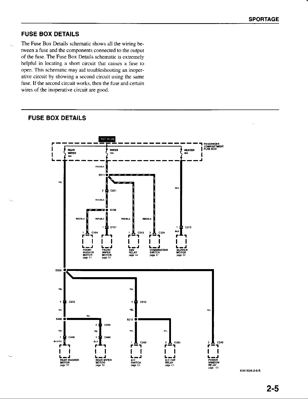
FUSE BOX DETAILS
SPORTAGE
The Fuse Box Details
tween a fuse and the components
of the fuse. The Fuse Box Details
helpful in locating a shon
open. This schematic may
ative circuit by showing a second
fuse. If
wires of the inoperative
the second circuit works. then the fuse
FUSE BOX DETAILS
F
I
I
schematic shows all the wiring
connected to the output
circuit that causes a fuse to
aid troubleshooting
circuit are
be-
schematic is extremely
inoper-
an
circuit using the same
and certain
good.
I
;l "."
rrr
tl
1
r
tl
1
tlll tl
li"_ ;1",,
ll ll
ll
KtA163A-2-GS
2-5
HOW TO
THIS MANUAL
USE
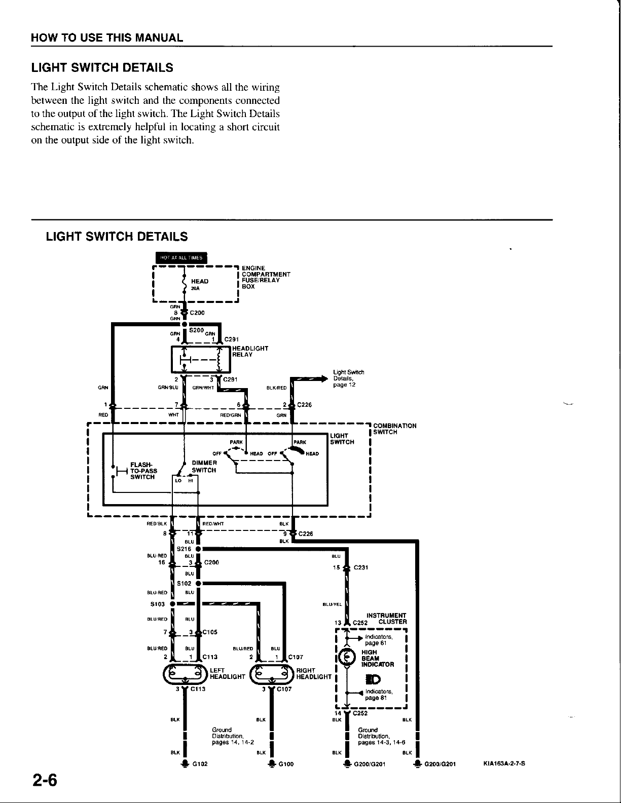
LIGHT SWITCH
The Light
Switch
DETAILS
Details schematic
shows all the wiring
between the light switch and the components connected
to the output ofthe light switch. The Light
schematic is extremely helpful in locating
on the output
LIGHT
side of the light switch.
SWITCH
DETAILS
Switch
Details
a shon circuit
ENGINE
COMPAFTMENT
I
FUSE/FELAY
I
BOX
I
HEAOLIGHT
. .
l-l
.
Ftastf
ToPAss
SwlTCH
16
COiIBINAnON
INSTFUiIENT
C252
psge
i ot
aE^
aotcttoR
D
pags
swtTcH
CIUSTEB
8l
81
LIGTIT
swttctt
- -- --- -J
8
1
BIGHT
HEADIIGHI
2-6
!
crou
4 czooiczor
* czoorozor
Ktat63a.2-7-S
SPORTAGE
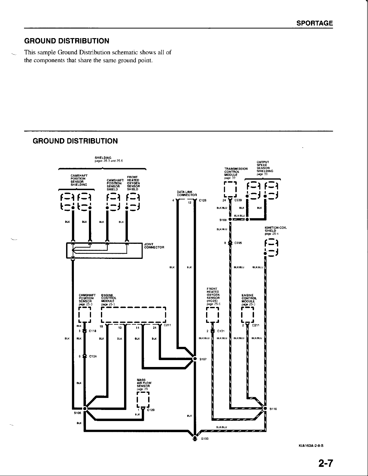
GROUND
This sample Ground Distribution schematic shows all of
the components that share
GROUND DISTRIBUTION
DISTRIBUTION
the same
SHIELDING
=l
f
f=l
'=i'=i
ground point.
f=t f=l
i-J i-J
3!i:8"
corlrRo!
i-l
c23::ffi!]-
L_j
sHrElgrNG
p.oe
re
f=t f=t
j-J
l-J
tl
L--------J
tl
SBtELO
f-t
i-,
ENGINE
tl
2A c211
2-7
HOW TO
THIS MANUAL
USE
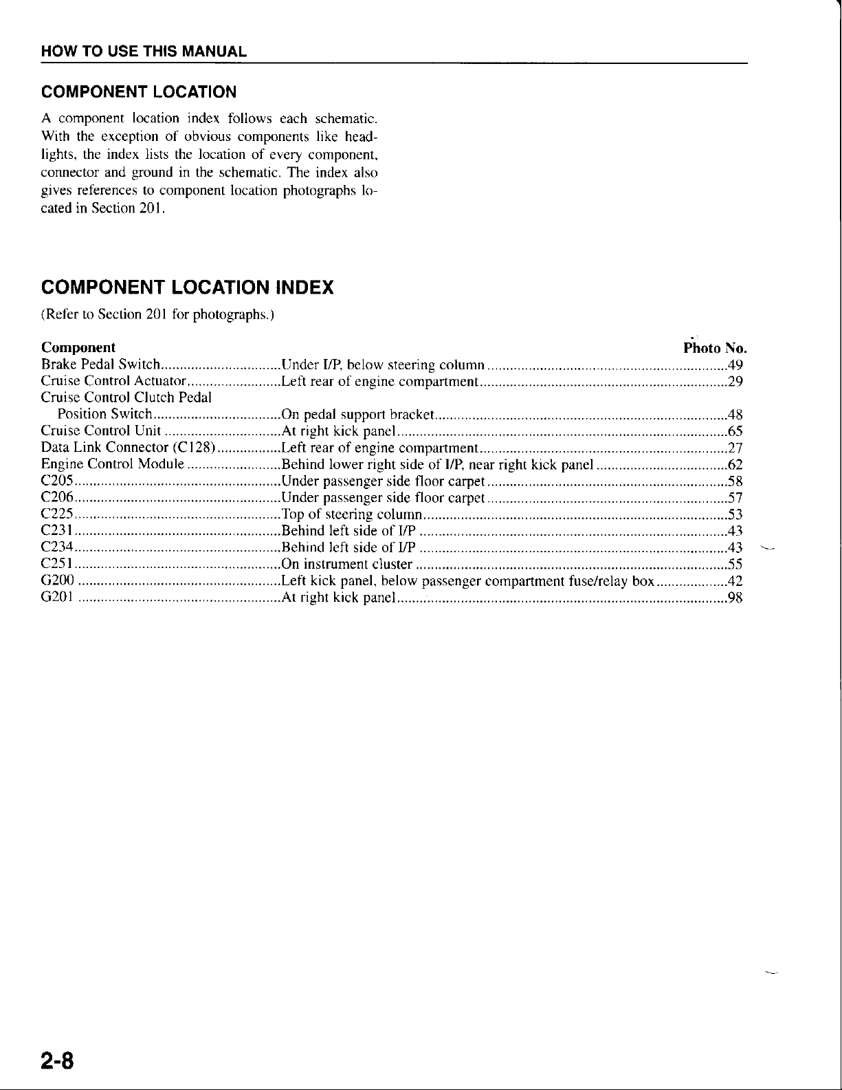
COMPONENT LOCATION
A
component
With
the exception of obvious components like
lights, the index lists the location
connector and
gives
references to
cated in Section 201.
location index
ground
in
the schematic. The index also
component location
follows each schematic.
head-
of every component,
photographs
lo-
COMPONENT LOCATION INDEX
(Refer
Component
to Section 201 for
Brake Pedal Switch................................Under
Cruise Control
Actuator.........................Left
Cruise Control Clutch Pedal
Position Switch...
Data Link
Connector
Engine Control Module............,............Behind
photographs.)
pedal
..On
(C
128).................Left rear
VP, below steering column..
rear of engine
support bracket....
of engine compartment.... .................................21
lower right
Photo No.
.................................49
compartment .....................................29
................48
side of
l/B
near right kick
panel
........... ........................62
G200 ...................
......Lefl kick
panel,
below
passenger
compartment fuse/relay box...................42
2-8
SPORTAGE
FIVE-STEP TROUBLESHOOTING
1. Verify the Problem
Tum on all the
components in the
check the accuracy of the customer
symptoms. Do not begin disassembly
have narrowed
down the
2. Analyze the
Look up the schematic for the
how the circuit is supposed
paths
from
nents to
the
ground.
problem
that share the same fuse,
referred to in each
shared circuits
circuits
work,
must be in the wiring used
several
circuits
power
the
Also, trace
circuit. The names of circuits
you
the shared wiring is
fail
problem
Circuit Schematic
problem
work
io
source through
circuits that sharc wiring with
ground,
circuit schematic. Try to
didn't check in step l. If
only by the
at the same time.
a likely cause.
Based on the symptoms and
circuit's operation, identify
your
one or more
problem
complaint. Note the
or testing until
area.
circuit. Determine
by tracing the current
the circuit compo-
or components
or switch, and so on, are
operate any
OK, and the cause
problem
fuse
the
or
understanding of the
possible
circuit to
you
shared
the
circuit. If
eround
causes.
Test Light
On circuits witbout
check for
with a
touch the other lead to various
where voltage should
there is
know how
ohmmeter
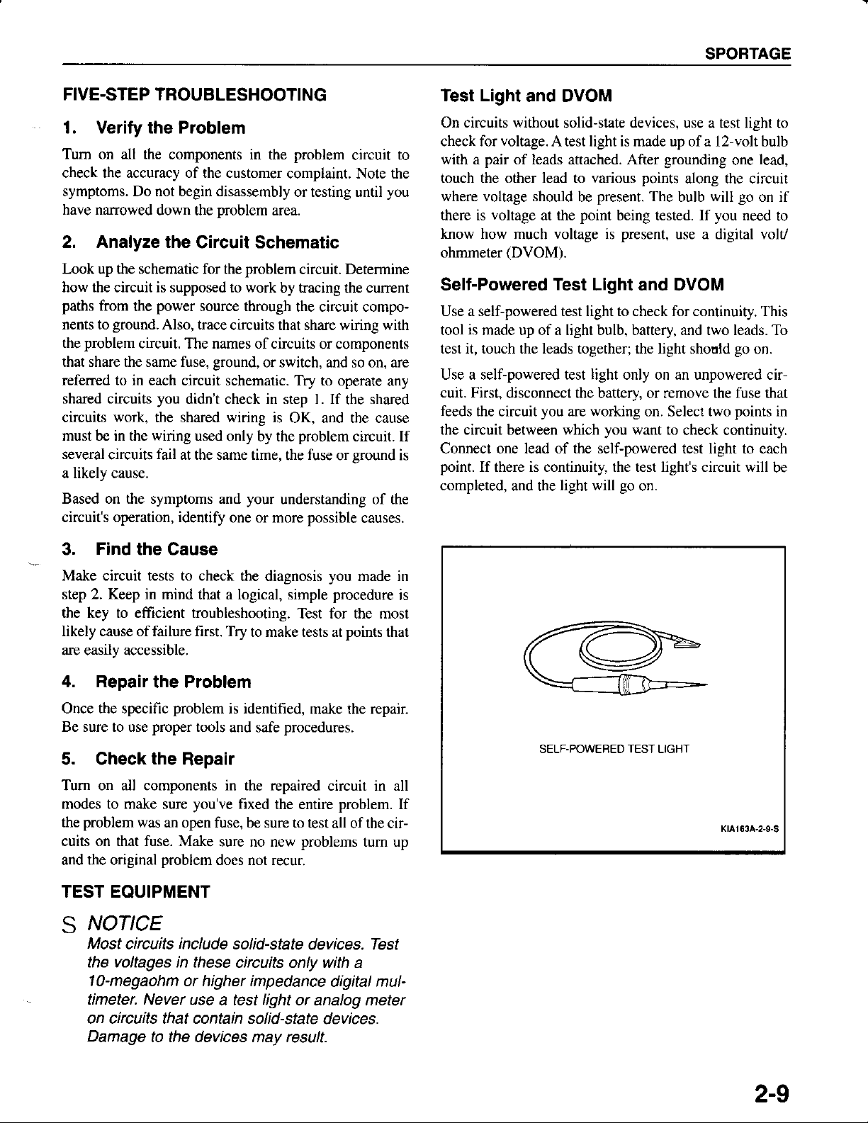
Self-Powered
Use a self-powered test light to check for continuity. This
is
tool
made up of a light bulb, battery, and two leads. To
test it, touch the leads together; the light should
Use a self-powered test light only on an unpowered cir-
First,
cuit.
feeds
the circuit
the circuit between which
Connect one lead of the self-powered test light to each
is
point.
If there is continuity, the test lighfs circuit will
completed,
and DVOM
solid-state devices, use a test light to
voltage.
pair
voltage
(DVOM).
disconnect the battery, or remove the fuse that
A test light is made up of a l2-volt bulb
of leads attached. After
present.
be
point
at the
much
you
and the
voltage
Test
are
light will
being tested. If
present,
is
Light and DVOM
working
you
go
grounding
points
want to
on.
along the circuit
The
bulb
use a digital volt/
on. Select two
check continuity.
will
you
lead,
one
go
on if
need
go
on.
points
to
in
be
Find
3.
Make circuit tests to check
step
2.
the key to efficient troubleshooting.
likely cause of failure first. Try
are easily accessible.
4. Repair
Once the specific
Be sure to use
5. Check
Tum on all components in the repaired
modes to make sure
problem
the
cuits on that fuse. Make
and the original
the Cause
Keep in
the Problem
proper
the
was
the diagnosis
mind that a logical, simple
Test for the most
to make tests at
problem
is identified,
tools
and safe
make the repair.
procedures.
Repair
you've
an open fuse, be sure to test
problem
fixed
the entire
sure no new
does not recur.
problems
TEST EQUIPMENT
NoflcE
s
Most
chcuits
the voltages in these
1o-megaohm
timeter. Never use
on circuits that contain solid-state
Damage
include
solid-state
devices. Test
circuits only with a
or higher impedance
a test
light
or analog meter
to the devices may result.
you
made in
procedure
points
that
circuit in all
problem.
all of the cir-
tum up
digital mul-
devices.
is
SELF-POWERED
If
TEST
LIGHT
KtAt63A,2-9-S
2-9
HOW TO
USE THIS MANUAL
E@
lll#r
KtA l63A-2n
0-S
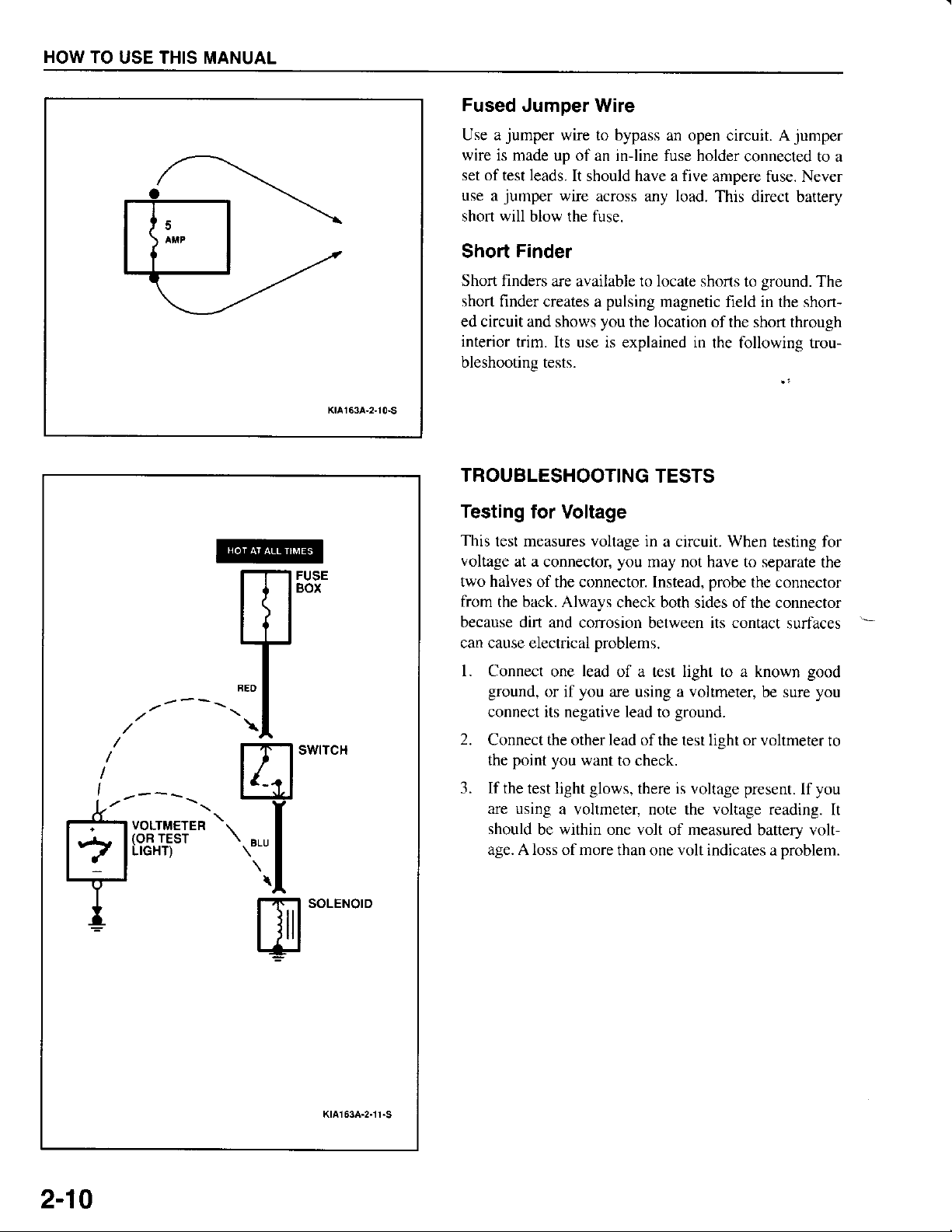
Fused
Use a
wire is made
set of test leads.
use
shon will blow the fuse.
Short
Short finders
short
ed circuit and shows
interior
bleshooting tests.
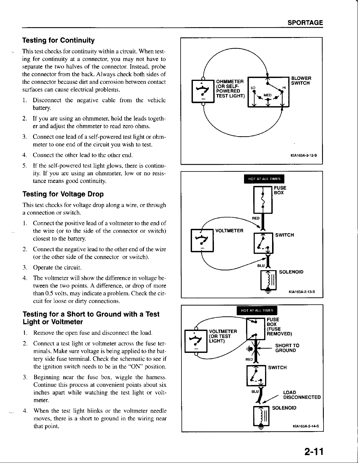
TROUBLESHOOTING
Testing
This
voltage
two halves
from
because dirt
can cause electrical
Jumper Wire
jumper
jumper
a
wire to bypass
up of an in-line fuse holder
It should have a five
wire across
any
Finder
are available to locate shorts
finder creates
trim. Its use is explained in
pulsing
a
you
the location of the short through
for Voltage
test measures voltage in
at a
connector,
of the connector Instead,
the back. Always
and corrosion between its contact
you
may not have to separate
check both sides of the connector
problems.
an open circuit. A
magnetic field in the shon-
TESTS
a circuit. When testing for
connected to a
ampere fuse. Never
load.
This direct battery
ground.
to
the following trou-
probe
the connector
jumper
The
the
surfaces
VOLTMETER
(OR
TEST
LIGHT)
v
--\l
El"*''""
'r\l
pl'o'-'"o'o
KtA163A-2nr-S
l. Connect
ground,
connect its negative lead
2.
Connect the other lead
point you
the
3. If the
test light
are using
should
age. A loss of more
lead
one
you
or if
want
glows,
a voltmeter, note the voltage reading.
be within one volt
of a test light to a known
are using a voltmeter,
ground.
to
of the test lisht or voltmeter
to check.
there is voltage present.
measured
of
than one
volt
indicates a
be sure
battery volt-
problem.
good
you
you
lf
to
It
2-10
Testing for Continuity
This test checks for continuity within a circuit. When tes!
ing for
separate
the connector
the connector because dirt and corrosion between contact
surfaces
1. Disconnect the negative cable from the vehicle
2. If
continuity
the two halves of the
can
battery.
you
are using an ohmmeter, hold the leads togeth-
and adjust the ohmrneter
er
at a connector,
from
the back. Always check both sides of
electrical
cause
you
may not have to
connector Instead,
problems.
read
to
zero ohms.
probe
SPORTAGE
BLOWER
swrTcH
3. Connect
meter to one end of the
4.
Connect the other
5. If the self-powered test light
ity. If
tance
one lead of a self-powered
circuit
lead
to the other end.
you
are using an ohmmeter, low or no resis-
means
good
continuity.
you
glows,
light
test
wish to test.
there is continu-
or
ohm-
Testing for Voltage Drop
This test checks for voltage drop along a wire, or through
a connection
l. Connect
the wire
closest to the battery.
2.
Connect
(or
3. Operate the circuit.
4. The voltmeter will show the difference in voltage be-
tween the two
than 0.5 volts, may indicate a
cuit
or switch.
positive
the
(or
to the side of the connector or switch)
the negative lead to the
the other side of the connector or switch).
for loose or dirty connections.
lead
points.
of a voltmeter to the end of
other end of
A
difference, or drop of
problem.
Check the cir-
the wire
more
Kta163A-2-12.S
Testing for a Short to Ground with a Test
Light
l. Remove the open fuse and
2.
Connect
minals. Make sure voltage is
tery side fuse terminal.
the ignition switch
Beginning near the fuse box, wiggle the hamess.
3.
Continue
inches apart while watching the test light or volt-
meter.
4. When the test light blinks or the voltmeter needle
moves, there is a short to
that Doint.
Voltmeter
or
disconnect the
a test light or voltmeter across the fuse ter-
being applied to the bat-
the schematic to see if
to be in the
ground
"ON"
points
in
the
this
needs
process
Check
at convenient
load.
position.
about six
wiring near
VOLTMETER
(oR
TEST
LIGHT)
FUSE
BOX
(FUSE
REMOVED)
TO
SHORT
GROUND
El'*''"'
'I-
b?s'%*n'""o
[u'o""o'*:^,*^...,,"
2-11
HOW TO USE THIS MANUAL
BATTERY
DISCONNECTED
OHMMETER
(oR
SELF.
ii'J+:IEBD
l-l-l SryITCH
| | |
l-td
".rf
L/
B
FUSE
BOX
(FUSE
REMOVED)
SHORT
GROUNO
TO
LoAr,
DrscoNNEcrED
SOLENOID
KrA163A-2n
5.S
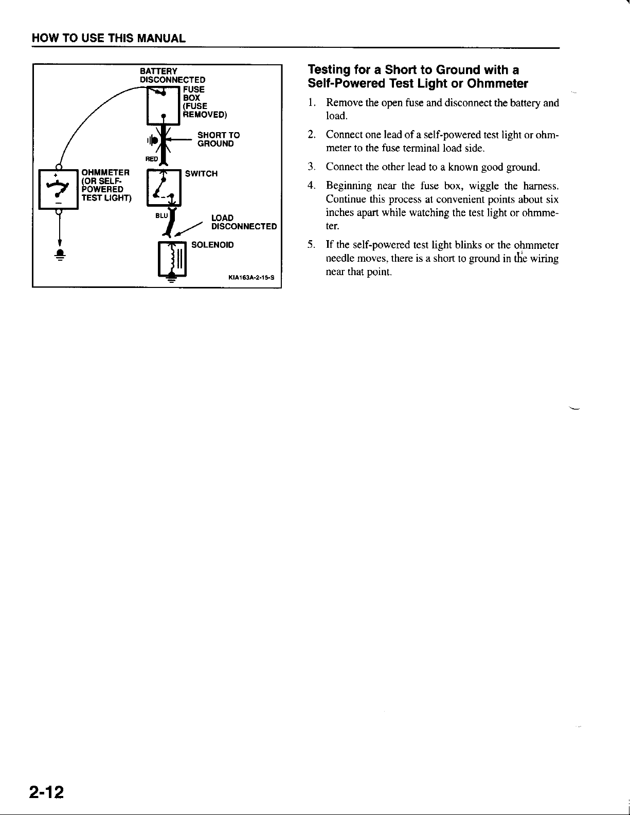
Testing
Self-Powered
l.
2. Connect one lead
3. Connect the other
4. Beginning
5. If
for a Short to
Test Light or
Remove the open fuse and
load.
of a self-powered test light or ohm-
meter to
Continue
inches
ter.
the self-powered test light blinks or
needle moves. there is a shon to
near that
fuse
the
this
apart
Doint.
terminal load side.
lead to a known
near the fuse box, wiggle
process
while
at convenient
watching the test light or ohmme-
Ground with a
Ohmmeter
disconnect the battery and
good
ground.
the hamess.
points
about
the ohmmeter
ground
in the
wiring
six
2-12
SPORTAGE
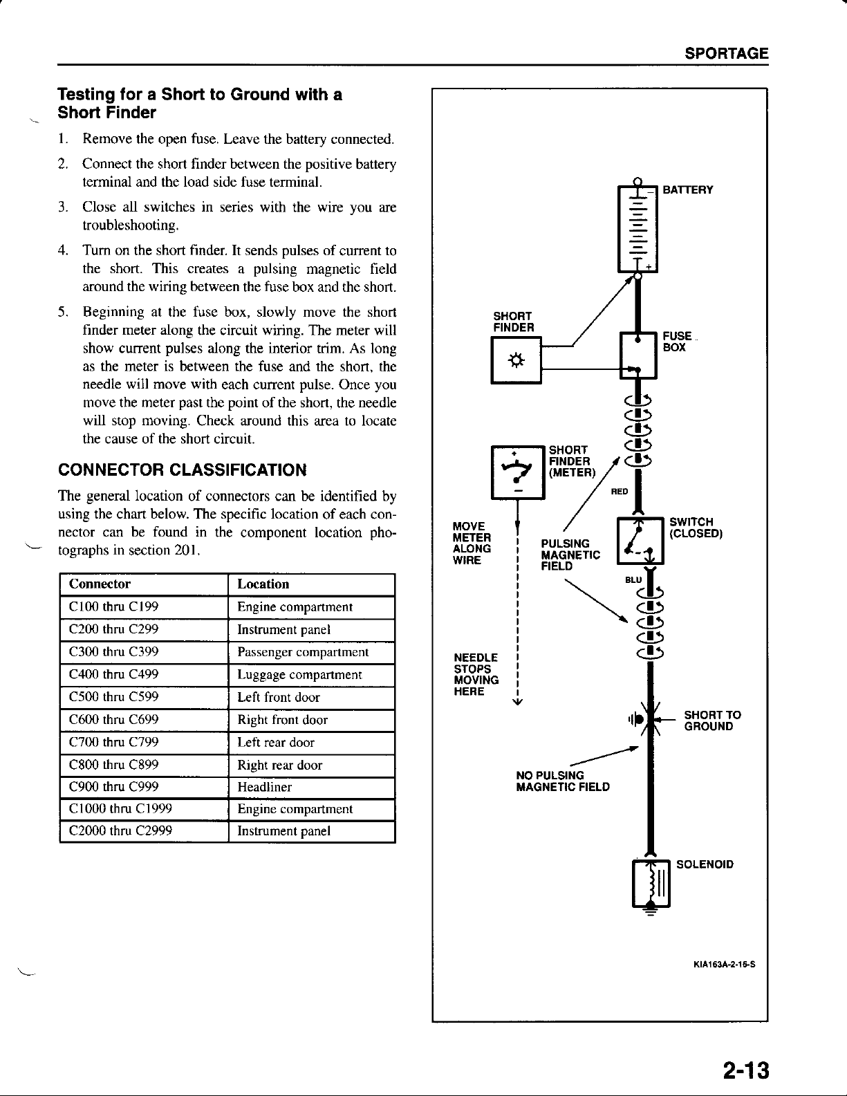
Testing for a
Short
to
Ground with a
Short Finder
l. Remove
2. Connect the short finder between the
terminal and the load side fuse terminal.
3. Close
troubleshooting.
4. Tum
the short. This creates
around the wiring between
5. Beginning at the fuse box, slowly move the short
finder meter along
show current
as the meter is between the fuse
needle will move with
move the meter
will stop moving.
the cause of the short circuit.
the open
all switches in
on the short
fuse.
Leave the battery connected.
positive
series with the wire
finder.
pulses
past
It sends
a
the circuit wiring. The meter will
along the interior
each cunent
point
the
Check around this area to locate
pulses
pulsing
fuse
the
box and the short.
and the shon. the
of the short,
of
magnetic field
trim.
pulse.
battery
you
current
As long
you
Once
needle
the
are
to
CONNECTOR CLASSIFICATION
general
The
using the chafi below. The specific location
nector can be found in
tographs
Connector Location
cl00 thru cl99 Engine
C200 rhru C299
C300 thru C399 Passenger compartment
C400 thru C499 Luggage
C500 thru C599
C600 thru C699 Right front
C700 thru C799 Left
C800
C900 rhru C999 Headliner
C1000 thru C1999 Engine compartment
C2000 thru C2999 Instrument panel
location
in
section
thru
C899 Right rear door
of connectors can be identified by
the component location
201.
Instrument
Left front door
of each con-
pho-
compartment
panel
companment
door
rear door
MOVE
METER
ALONG
WIRE
NEEDLE
STOPS
MOVING
HERE
BATTEBY
FUSE
gox
<!>
=lP,T.??l /8
'l'-7.-l
|
i
i
i \<!>
i
i
i
il
'
il!8iiii|?,*"
/
Flt's]re'"
.t...
rF-l |JI88E",
ll+l
*U
\<D
<!)
<f)
,rf.-
t*tt**
I
I
I
to"*o'o
ffi
Kla163A-2n 6-S
2-13
HOW
TO USE THIS
MANUAL
Wire
Side Of
Female
Terminals
Terminal
Male Terminals
Side
KtA163A-3.1.S
Of
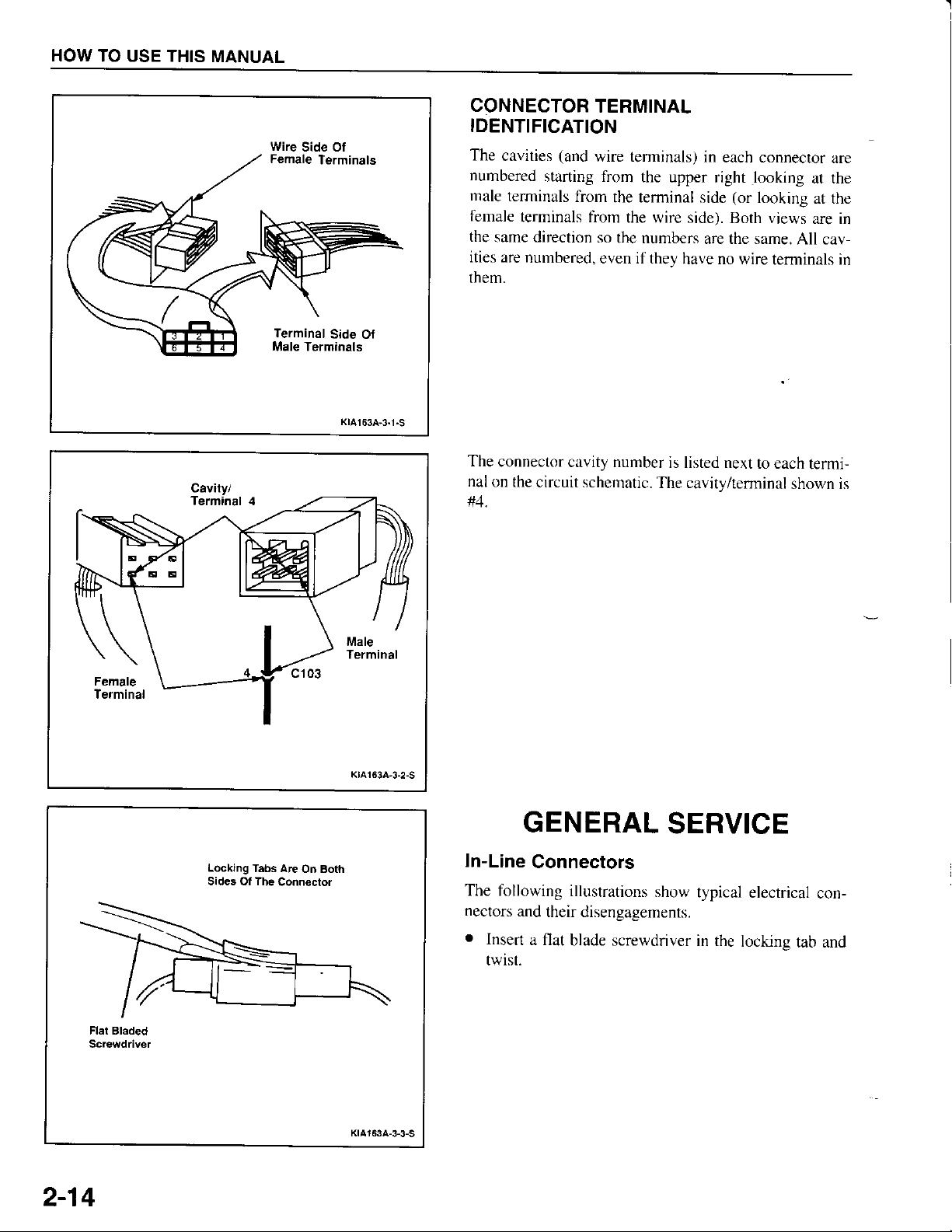
CONNECTOR
TERMINAL
IDENTIFICATION
The
cavities
numbered
male
terminals
female
the
same direction
ities are
them.
The
connector
nal
on the
#4.
(and
wire teminals)
starting from
from
the terminal
terminals fiorn
numbered,
the wire
so
the numbers
even if they
cavity number
circuit schematic.
in
each connector
the upper right
side
looking
(or
looking
side). Both views
are the same.
have no wire
is listed next
to each
The cavity/terminal
are
at the
at the
are in
All cav-
terminals in
termi-
shown is
Flel Bladed
Screwdriver
2-14
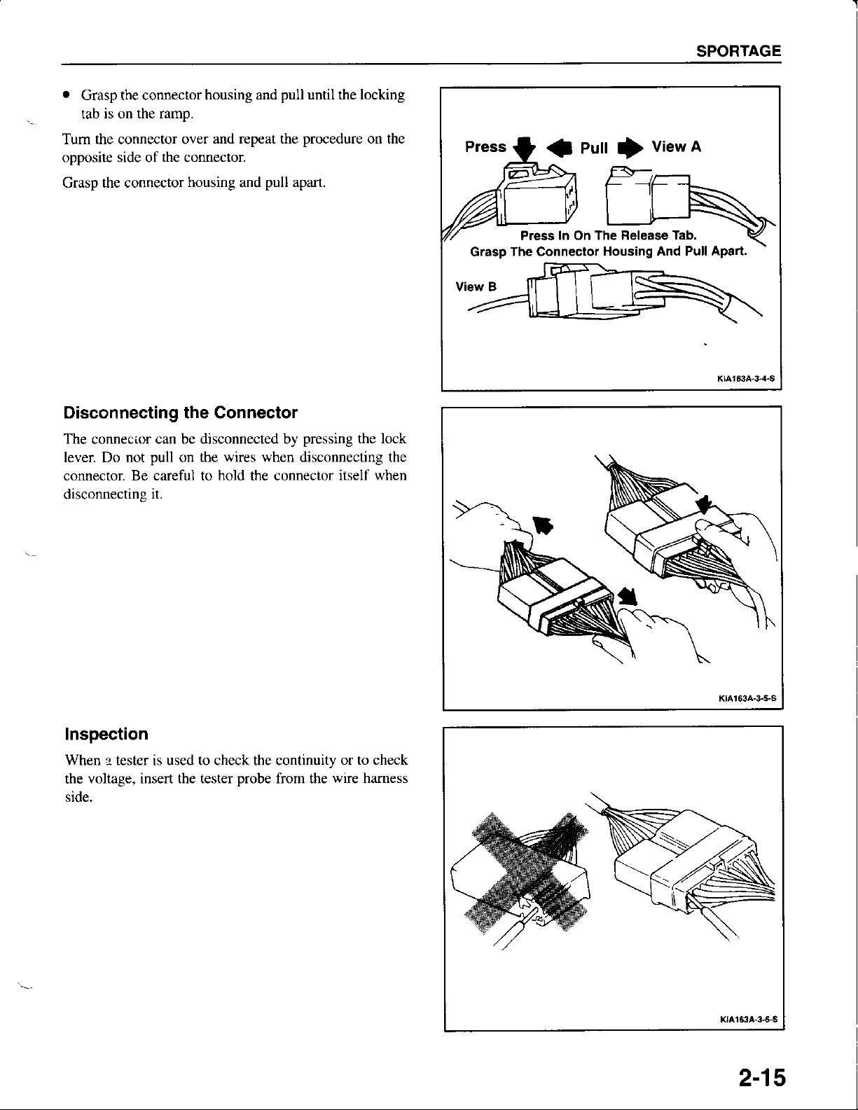
Locking
Tabs Are
Sides Of The
On Both
Connector
Kta163A,3-2-S
KtA153A-3-3-S
GENERAL
In-Line
The fbllowing
nectors
.
Connectors
and
Insen
a flat
twist.
their disengagements.
SERVICE
illustrations
blade screwdriver
show
typical
in the
locking
electrical
tab and
con-
SPORTAGE
.
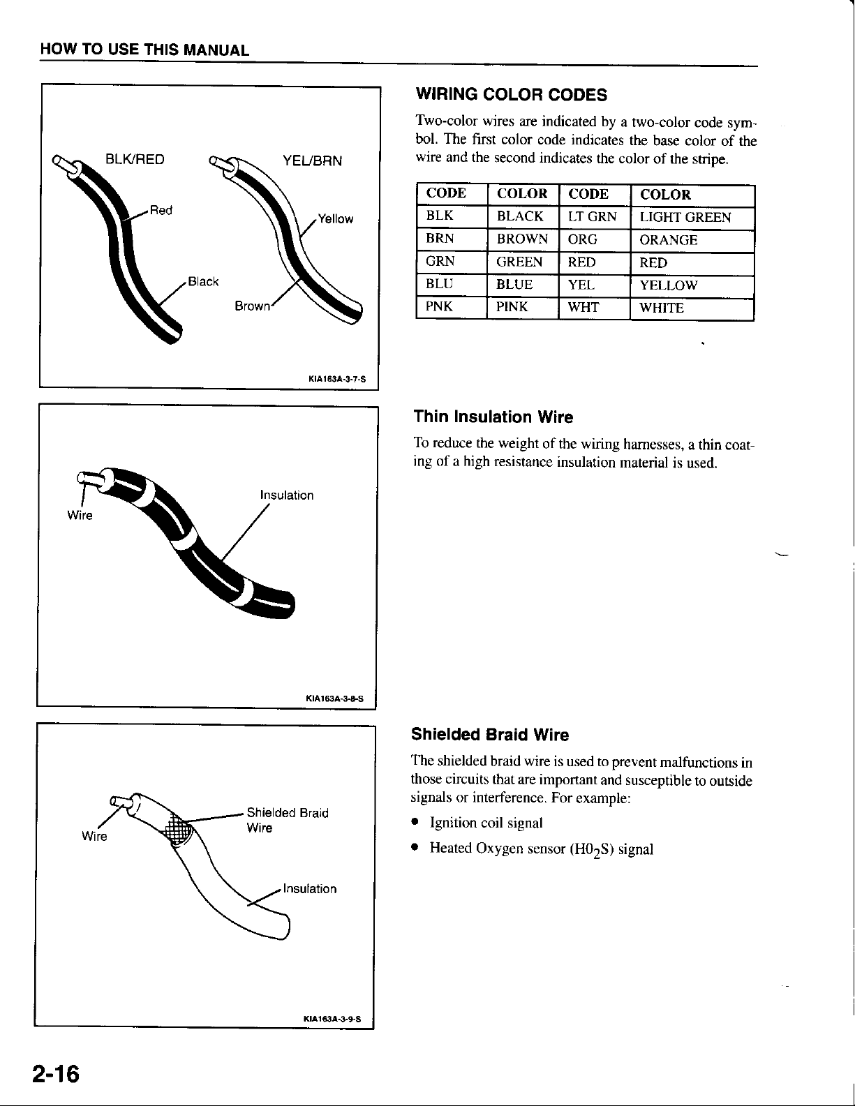
Grasp the connector
is on the ramp.
tab
Tum the connector over
opposite side of the connector
Grasp the connector
housing and
and repeat the
housing
and
pull
pull
Disconnecting the Connector
The
connecior
lever Do not
connector. Be careful to
disconnectins
can be disconnected by
pull
it.
the wires when disconnecting the
on
hold
the connector
until the locking
procedure
apart.
pressing
on the
the lock
itself when
The Connectof
Grasp
eutt
J
In On The Release
Press
vie*l
I
Tab.
Housing And Pull Aparl.
Inspection
When l tester is used to check the continuity
voltage, insert the tester
the
side.
probe
from the
wire hamess
K|^r63a-+5-s
or to check
Klal63A-3-GS
2-15
HOW
TO
USE THIS
MANUAL
KtAt53A-3-7-S
WIRING
Two-color
bol. The
wire
CODE
BLK
BRN
GRN
BLU
PNK
COLOR
wires
first color
and the
are indicated
second indicates
COLOR
BLACK
BROWN
GREEN RED
BLUE
PINK
Thin Insulation
To reduce
ing of a high
the weight
resistance
CODES
by
a two-color
code indicates
the color
CODE
LT
GRN LIGHT
ORG
YEL
WHT WHITE
Wire
of the wiring
insulation
hamesses,
material
the
base color
of the stripe.
COLOR
ORANGE
RED
YELLOW
is used.
code sym-
of the
GREEN
a thin coat-
2-16
Klat634-$&5
Insulation
KtA163A-3-95
Shielded Braid
The
shielded
those circuits
signals
.
Ignition
o
Heated
braid wire
that
are important
or interference.
coil signal
Oxygen sensor
Wire
is used to
For
prevent
and susceptible
example:
(H02S)
signal
malfunctions
to outside
in
SPORTAGE
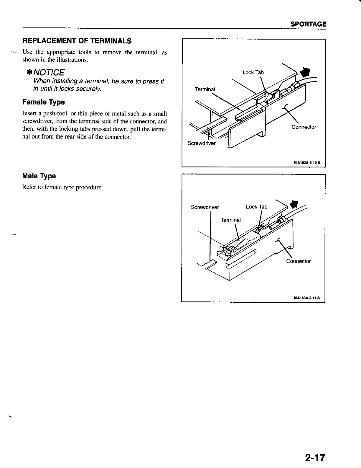
REPLACEMENT
'.-
Use the appropriate
shown in
the illustrations.
*NOTICE
When
in until it locks
Female
Insert
screwdriver,
then, with
nal
out from the rear
Male Type
Refer
installing
Type
push-tool,
a
from the
the locking tabs
female
to
TERMINALS
OF
tools to remove
a terminal,
securelv-
or thin
type
piece
terminal side
pressed
side of the connector.
procedure.
the terminal,
pull
press
as a small
rhe
be sure to
of metal such
of the connector, and
down,
as
it
termi-
2-17
FUSE/RELAY INFORMATION
tE rFT_l
eur,ri'
I
I
RELAY
I
I
X
l-ci_l
MAIN
I
I
RELAY
I
I
[Tqr-f--] f-l-*l'-t--l
f-w__l
MEX
l0Al l5. l l0"l l5dl l.0Al l.0Al | |
I
-^
11,".""1
0,o..
Jl
s o"
,o",\
ll
FooM
ll
ll><l
HtrHtrHMH
trtrtrtrtrH
XXXEiXG@
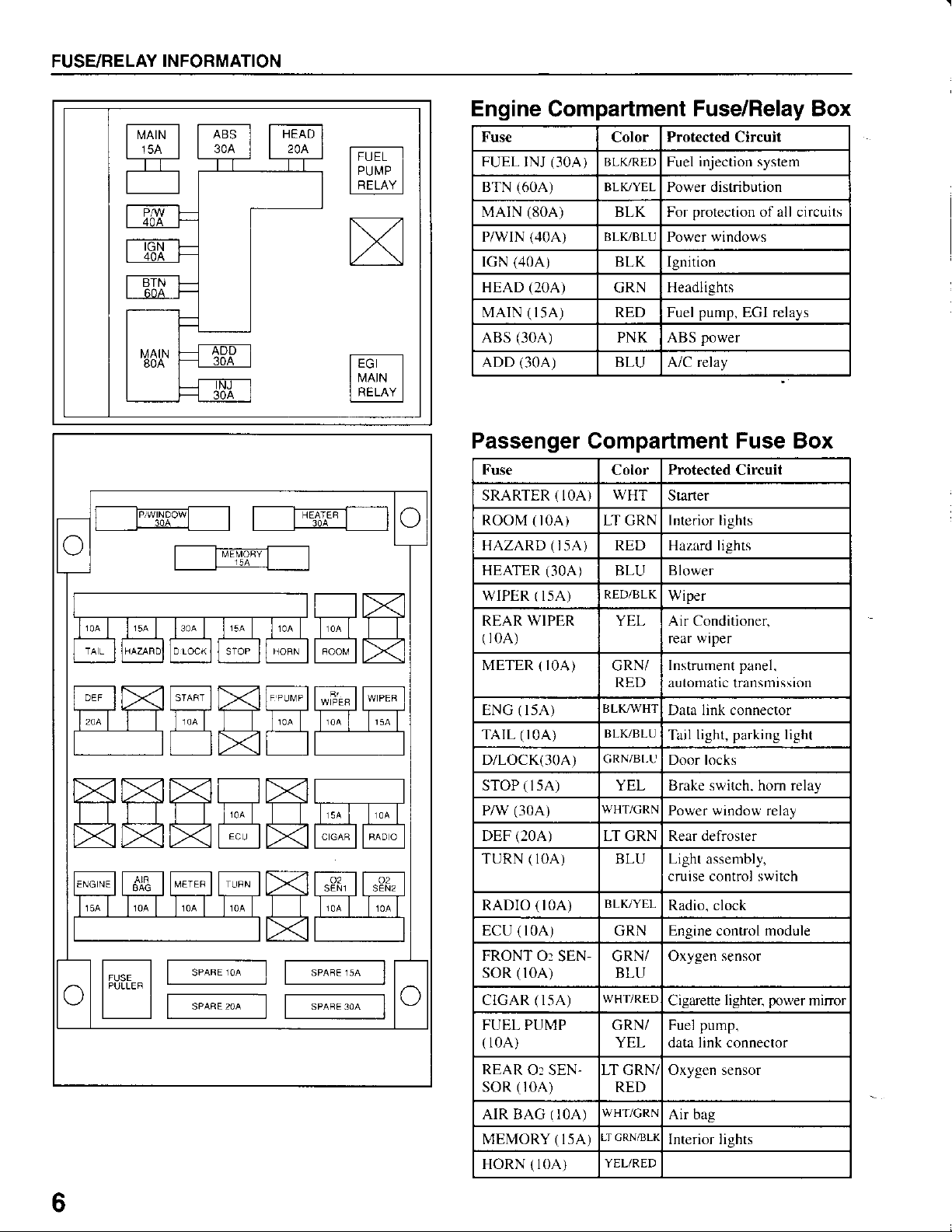
Engine
Fuse
FUEL
BTN
MArN
P/wlN
rGN
HEAD
MArN ( l5A) RED Fuel
ABS
ADD
Compartment
Color
INJ
(60,4)
(80A)
(,10A)
(40A)
(20A)
(30A)
(3OA)
(3OA
BLK-/RED
)
BLK/YEL
BLK For
BLK,/BLU
BLK Ignition
GRN
PNK ABS
BLU A/C relay
Fuse/Relay Box
Protected Circuit
Fuel injection system
Power distribution
protection
Power windows
Headlights
pump,
power
of all circuits
EGI relays
Passenger Compartment Fuse Box
Fuse
SRARTER ( IOA
r0A)
(30A)
(2OA)
(
t0A) LT GRN
(l5A)
(3OA)
(l5A)
WIPER
(l5A)
ROOM
HAZARD
HEATER
WIPER
REAR
(
METER { IOA)
ENG
TArL ( r0A)
D/LOCK(30A)
sToP ( lsA) YEL Brake switch. horn relay
PAV
DEF
TURN ( l0A) BLU Light assembly,
Color
WHT
}
RED Hazlrd lights
BLU
RED/BLK
YEL Air Conditioner.
GRN/
RED
tsLK/WHT
BLK-/BLU
GRN/BI-U
WHT/GRN
LT GRN Rear defroster
Protected
Starter
Interior lights
BI0wer
Wiper
rear
Instrument panel.
automatic
Data link connector
Tail
Door locks
Power window relay
cruise control switch
Circuit
wiper
transmission
light, parking light
ffiffiwHmffiffi
.,"""
-_l
sPAq, oa
f"^*;_l
."0".*_l
|
|
6
Gl
IPULLEF|;________]-
I l l
t
RADIO ( t0A)
ECU ( l0A)
FRONT O:
soR
CIGAR ( 15,A)
FUEL PUMP
(
l0A)
REAR
soR ( r0A)
AIR BAG ( IOA)
MEMORY ( I5A)
HORN ( l0A)
SEN-
(l0A)
Or SEN-
BLK,/YEL
GRN
GRN/
BLU
WHT/RED
GRN/
YEL
LT GRN/
RED
WHT/CRN
-I GRN/BLK
YEL/RED
Radio, clock
Engine
Oxygen
Cigarene
Fuel
data link connector
Oxygen sensor
Air bag
Interior lights
control
pump.
sensor
lighter.
module
power
minor
SPORTAGE
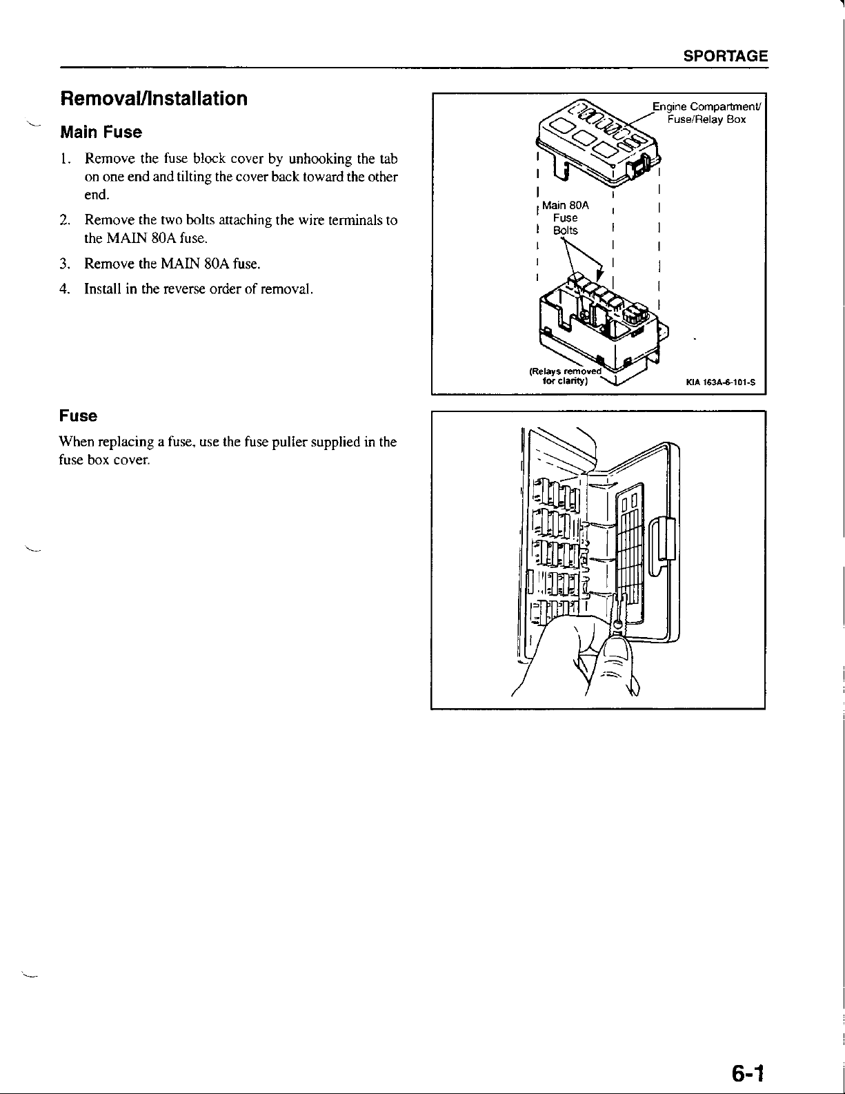
Removalflnstallation
Main Fuse
l. Remove the
on one end and tilting the cover
end.
Remove the two bolts attachins
2.
the MAIN 80A fuse.
Rernove the MAIN
3.
4. Install in the reverse order of removal.
Fuse
When replacing a fuse, use the
fuse box cover
fuse
cover
block
80A fuse.
by unhooking the tab
toward
back
wire
the
puller
fuse
CompartmenV
the other
terminals to
Kta t63A+101-s
supplied in the
.S
nffi
HHJ
ffi
I]:|:.]EEI
6-1
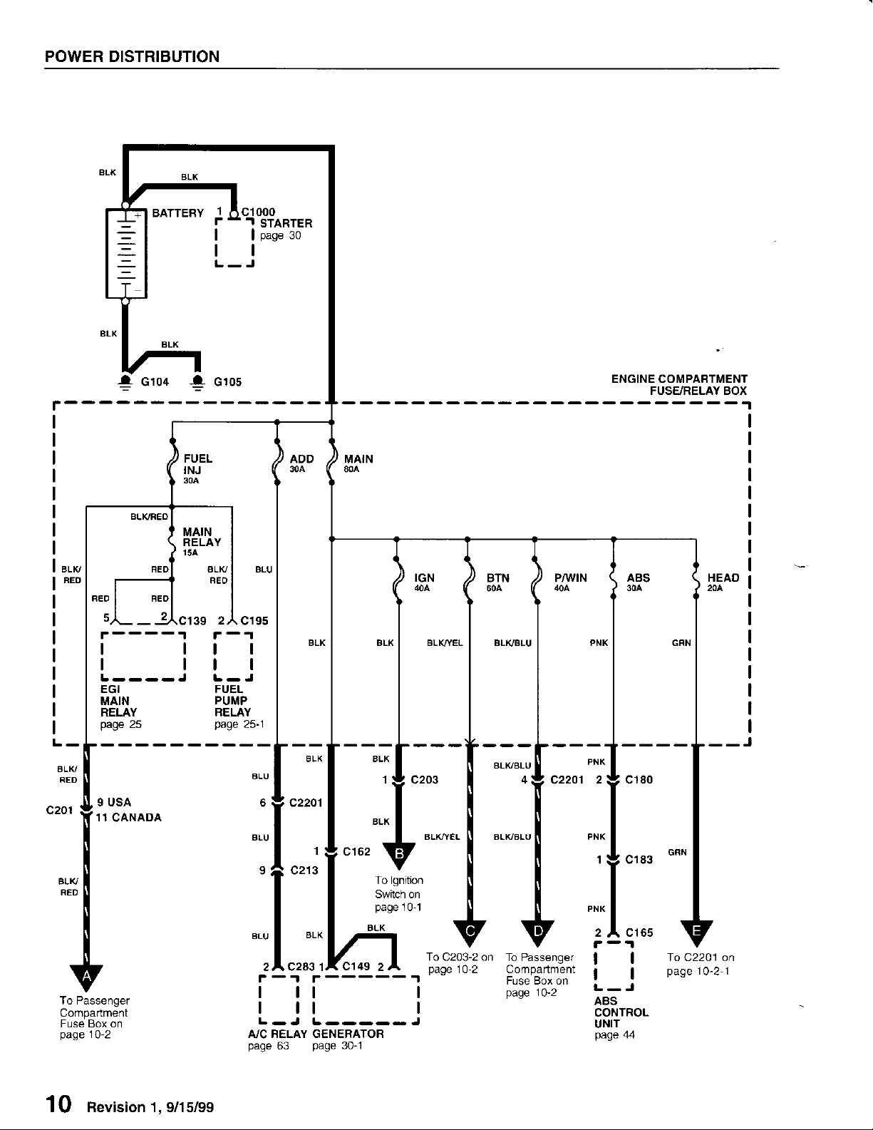
POWER DISTRIBUTION
BATTEBY
'I
6
- -.I
f-1cr
r
| |
tl
L-J
C'IOOO
STARTER
page
30
r------
FEO BEO
BLK/
FED
c201
I USA
11
c1o4 ! clos
4
FUEL
INJ
BLK/FEO
MAIN
RELAY
15A
ALK/
FEO
2z\
39
tl
ll
L----J
EGI
MAIN
RELAY
page
25
CANADA
C195
ll
ll
FUEL
PUMP
RELAY
page
25-1
c2201
ENGINE COMPABTMENT
FUSE/RELAY BOX
BLK/YEL BL|vBIU
--J
BLK/BLU
2
c2201
'I
BLK,^YEL
BLK/BLU
c180
To Passenger
Compartment
Fuse Box on
page
10-2
10 Revision 1, 9/15/99
c213
2 A C283 1x
- -r r ----- 't
r
BLK
Cl49
To lgnition
Switch on
page
101
2
I tt I
I tt I
L-J
A/C FELAY GENERATOR
page
L ----- J
63
Page
30-1
To C203-2 on
page
10-2 Compartment
To Passenger
Fuse Box on
Page
10-2
2
C165
A'
ll
tl
L-J
aas
CONTROL
UNIT
page
44
To C2201 on
page
10-2 1
From Engine
Compartmenl
Fuse/Relay
page
on
Box
10
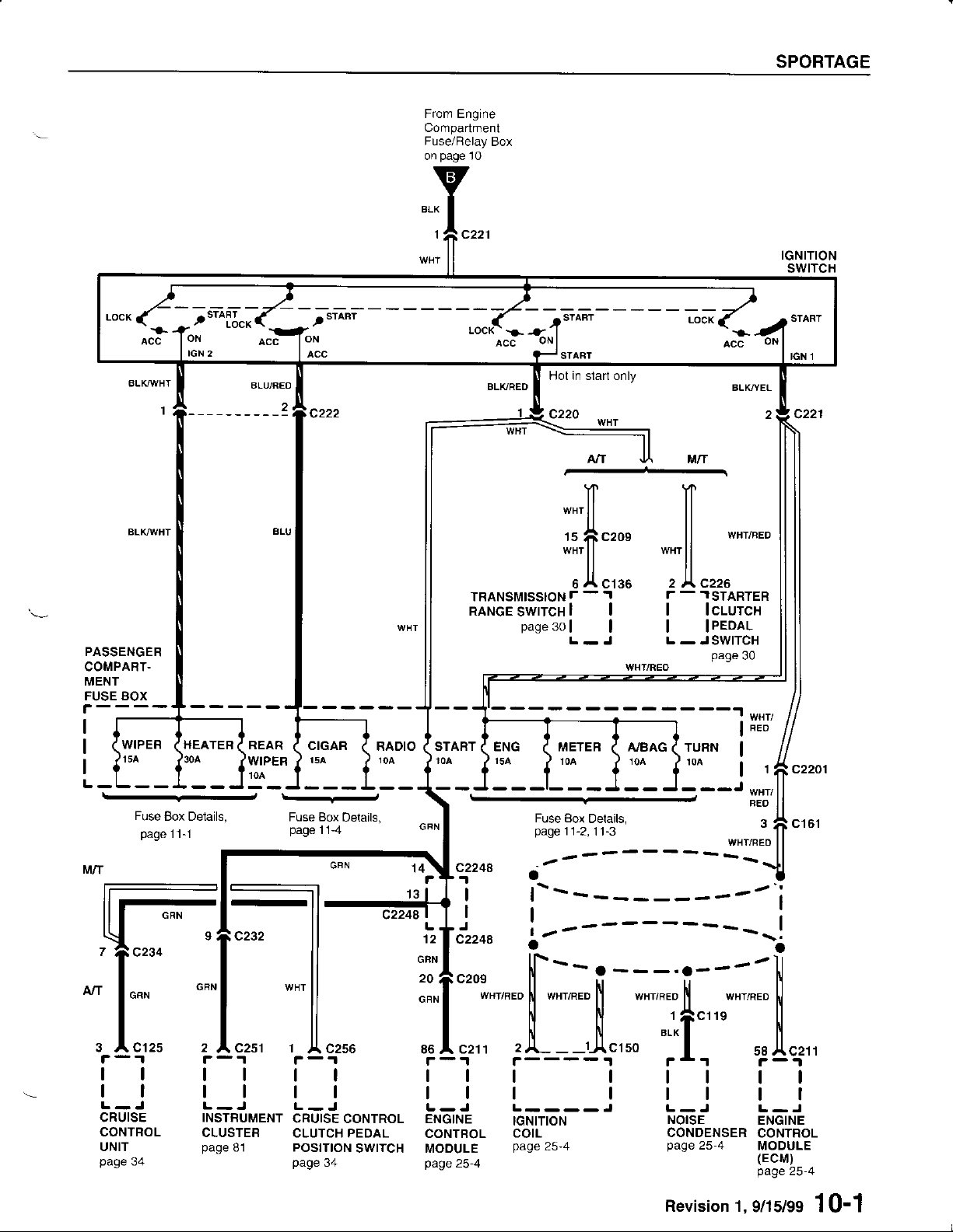
SPORTAGE
IGNITION
swtTcH
PASSENGER
COMPART.
MENT
FUSE BOX
WIPEF HEATER
- -s-iiilf
REAR
d
WIPER
-
--r-sr-mi
CIGAR
t5a
Jrii:tfi+8}i-l
RADIO ( START
.
ENG
Hot in siarl only
c220
"*ll
15
"*ll
e A crgs
page
30
| I
L-J
METER
NI
n
fi
c2oe
i/uT
'tl
tl
ll
wHr
ll
tl
2 )\ C226
-
1STARTER
r
I lclurcx
I IPEDAL
L -
JSWITCH
WHI/REO
A/BAG 1 TURN
BLK,ryEL
"rnr".o
page
30
START
IGN 1
c221
c2201
1
Fuse
Box Delails,
page
11-1
1l
tl
CRUISE
CONTROL
UNIT
page
34
--
2
C251
l'-'r
tl
tl
L-J
INSTFUMENT
CLUSTEB
page
81
Fuse Box
page
r-1
11-4
Delails,
tt
tl
L.J
CRUISECONTROL
CLUTCH PEDAL
POSITtON
page
SWTTCH
34
FEO
Fuse Box
page
qi
1
i
t---------a-2
ll
l
if
tro"
"-----
"#1";;
o""l
*"r,".o
,:lr"
rrt
llt ttttl
L-J L----J
ENGTNE
CONTBOL
MOOULE
page25-4
f
fl
;l----{",,. *1"]" *t*"
tcNtloN
COIL
page
Details,
11-2,
11-3
--
,r"r,".o
25-4
i
fl
c161
WHT/BED
------,1
'r"r,".o
25-4
--il
I
L-J
ENGTNE
CONTROL
MODULE
(EcM)
page
25-4
9nsl99 10'1
---';--
*nr,".o
ttttl
fl
L-J
NotsE
CONDENSER
Page
Revision 1,
POWER DISTRIBUTION
From Engine
Comparlment
Fuse/Relay Box
on
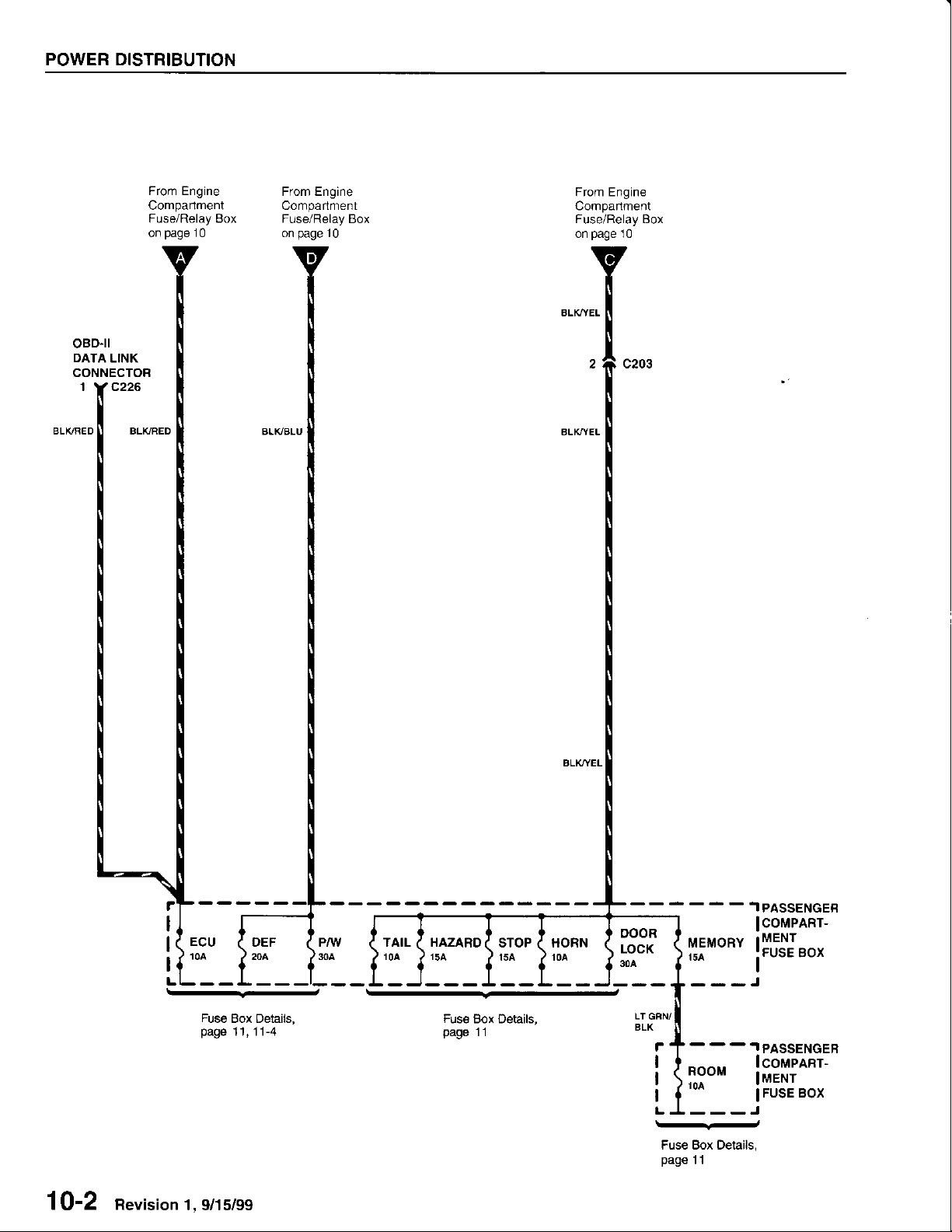
oBD-tl
DATA
LINK
CONNECTOR
1 Y C226
page
10
From Engine
Comparlment
Fuse/Relay
page
on
Box
10
From Engine
Comparlment
Fuse/Relay Box
page
on
10
1
0-2
nevision
1 , 9/15/99
Fuse
Box Details,
page
11,11-4
TAIL
10A
HAZARD
Fus€
Box Details,
page
11
- .T
PASSENGEB
HORNSTOP
oooR
LOCK
30A
i/|EYgPY l
rsa
ROOM
---J
lcoMPARr-
MENT
Box
iFusE
.I
PASSENGEF
lcomplnr-
IMENT
FUSE BOX
I
--
Fuse Box Details,
page
I l
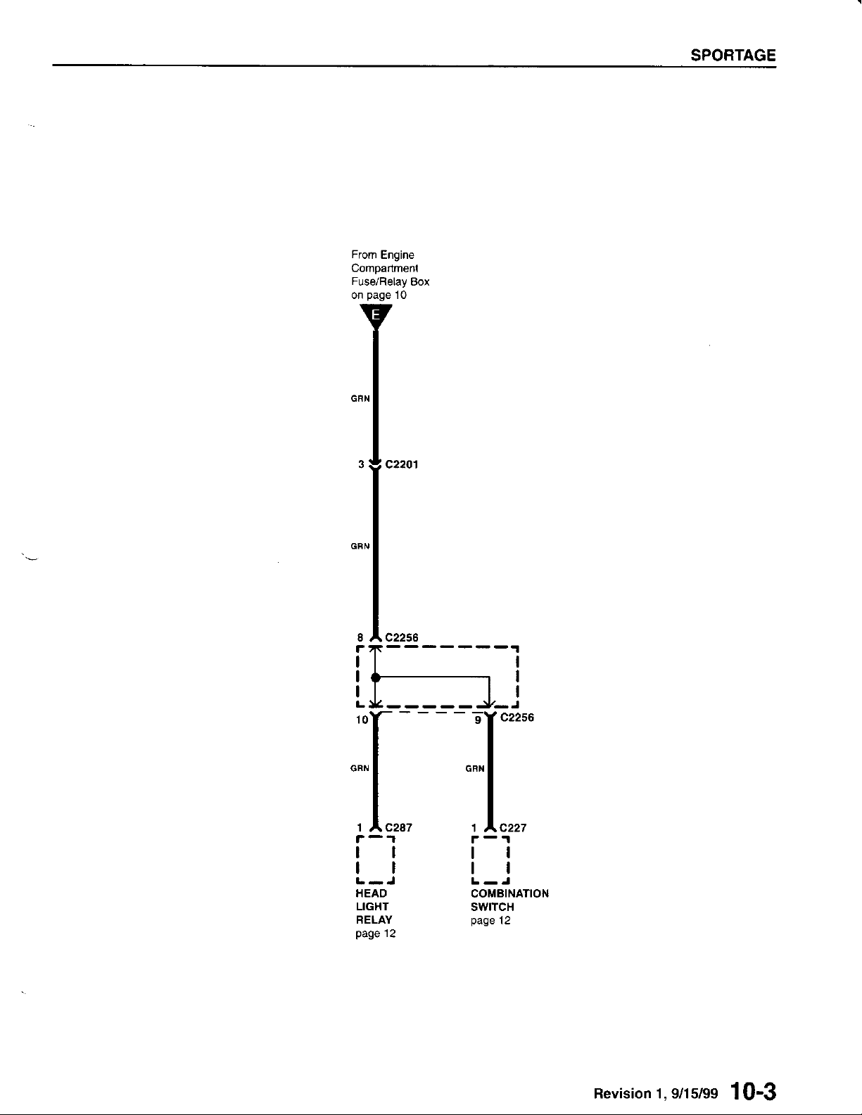
SPORTAGE
Revision 1, s/ls/gs
1
0-3
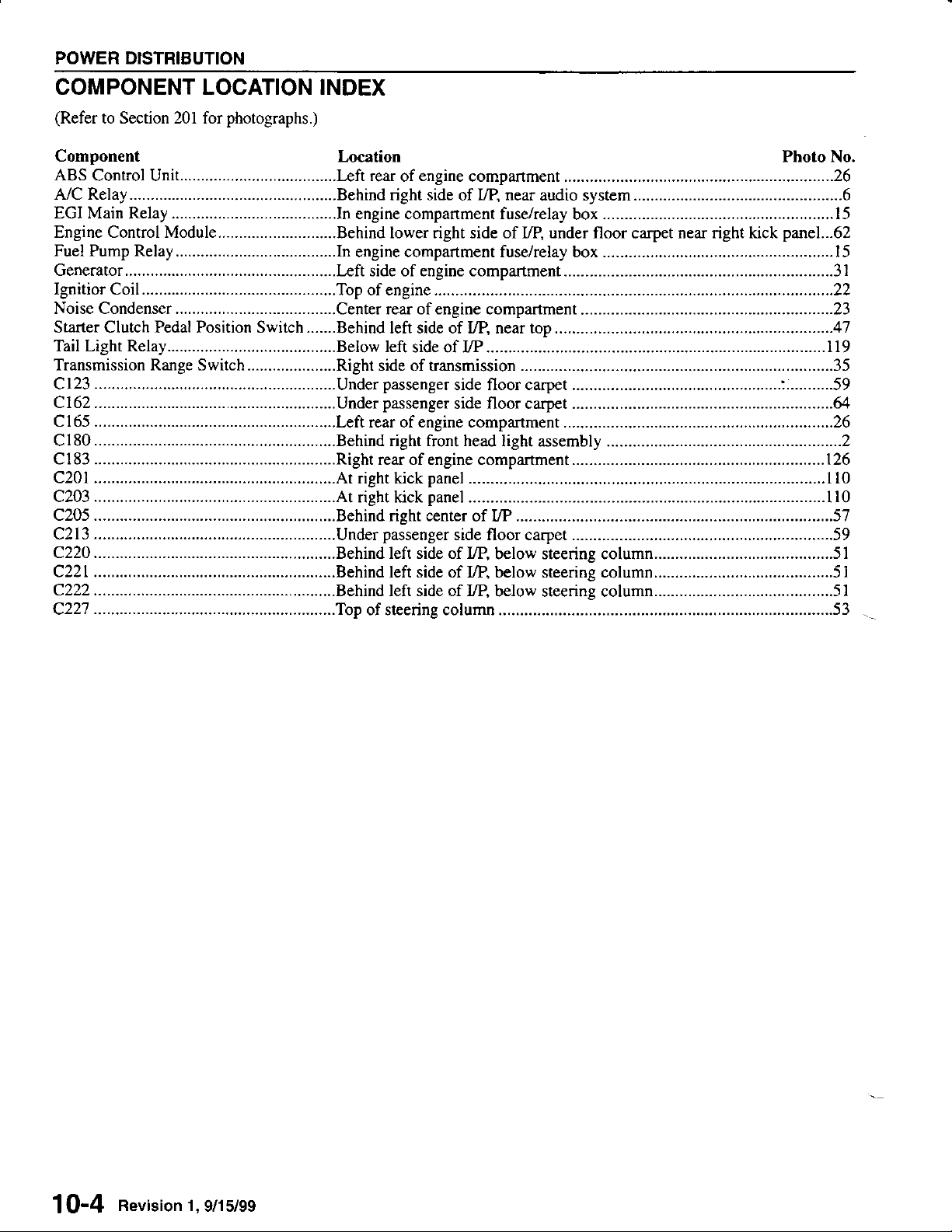
POWER DISTRIBUTION
COMPONENT
(Refer
to Section 201
Component
LOCATION INDEX
for
photographs.)
Location Photo No.
I Q-{
nevision 1,9/15/99
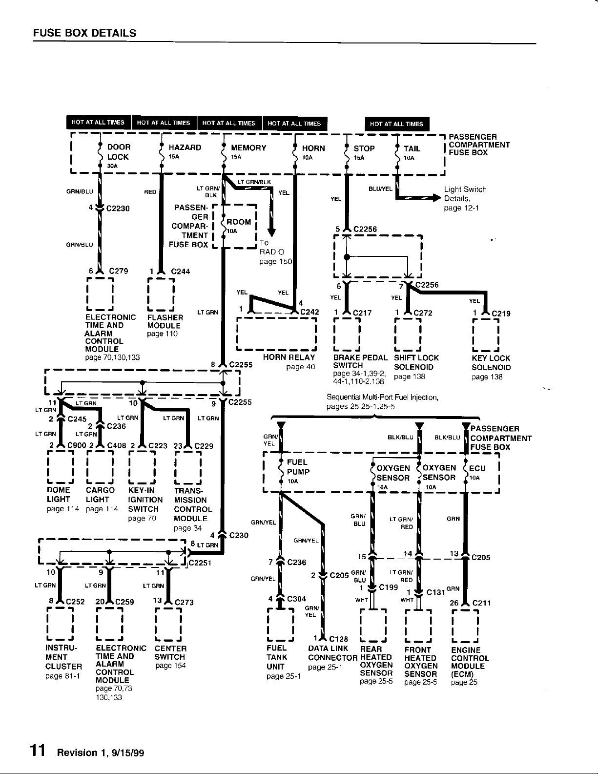
FUSE
BOX DETAILS
r--l---'
o
ooon
|
LocK
":-
I
cr..o
f
|
| )
L-J
o"nrua,
I
o"","au
I
I
s
A czzs
tl
ll
ELECTRONIC
TIME
AND
ALARM
CONTROL
MOOULE
page
70,130,I33
I
LJ,--____.
""ilH;"::
PASSEN-
COMPAR-
FUSE BOX
FLASHER
MOOULE
page
110
LTGFN/
GER
TMENT
BLK
T
9
LiGFNBLK
BOOM
YEL
'I
I
I
L------J
c2255
1
I
J
To
RADIO
c242
HORN RELAY
page
HORN
I
I
"if,.
r-1
I
tl
I
tl
BRAKE
SWITCH
40
page
44-1.110-2.13A
Sequential ft,4ulti-Port
pages
25,25-1,25-5
STOP
BLI'YE
c2256
PEDAL
34-1,39-2,
---.IPASSENGER
TAIL
t0a
I
I
I
Lighl Switch
Details,
page
{l:
r-'t
tl
tl
L-J
SHIFI LOCK
SOLENOID
page
T38
Fuel Injection,
COMPABTMENT
FUSE BOX
12-1
r-1
tl
L-J
KEY LOCK
SOLENOID
page
138
-'r
F
rt
I
rr
I
L-J L-J
DOME
LIGHT LIGHT
page
114
I
L-
10
LT GFN
tl
ll
INSTRU-
MENT
CLUSTER
page
81-1
r-1
I
tl
CARGO
page
114
'r",.IGFN
LT
20
c259
tl
tl
ELECTRONIC
TIME AND
ALARM
CONTROL
MODULE
page
7Q,73
130,133
r-.t
I
L-J
KEY.IN
IGNITION
SWITCH
page
70
11
GFNLT(
tt
tl
CENTEB
SWITCH
page
r-'t
tl
tl
L-J
TBANS.
MISSION
CONTBOL
MOOULE
page
34
154
c230
GRN/ll
;+-
(5Ui
!
I
lloA
-T\
cnrureL
I
lo'
z
ficzr
c"*,tea
I
:tT'
lt
tl
L-J
FUEL
TANK
UNIT
page
Daqe
I' tersserucen
ALK/BLU
I
I I
i----.r--'t
(o'''
|ffii {o,,"o."
,oo
---]t---T-
dffi"."" {:..1
l---
\ll
\
o"u,'..
c236
|
"J.Y
""J.+
|
I i i
15ts--1+-
":i,+
""'
"'::":i+
.,,.'
't
J
t,-1
25-1
Y
gl*i
*l
|
rItttl
IAC128
DATALINK
CONNECTORHEATED HEATED
oaoe 25_1
'
r4r
|
|
L-J
REAF
oxYGEN
SENSOR
page
25,S page
oxYGEN
'SENSOF
10Alr
t---r---
cFN
|
[ '.1^ -
|---1t/zu5
o""
cr rt
"'
;
r4r
rll
|
|
rtl
L-J
FRONT
NT ENGINE
TED CONTROL
GEN MODULE
OXYGEN
soR
SENSOR
25-5
25-5
II COMPARTMENT
ruse eox
(Ecu
JloA I
I
I
I
T
I
f
26
l' C211
(EcM)
page
25
I
11 Revision
1, 9/15/99
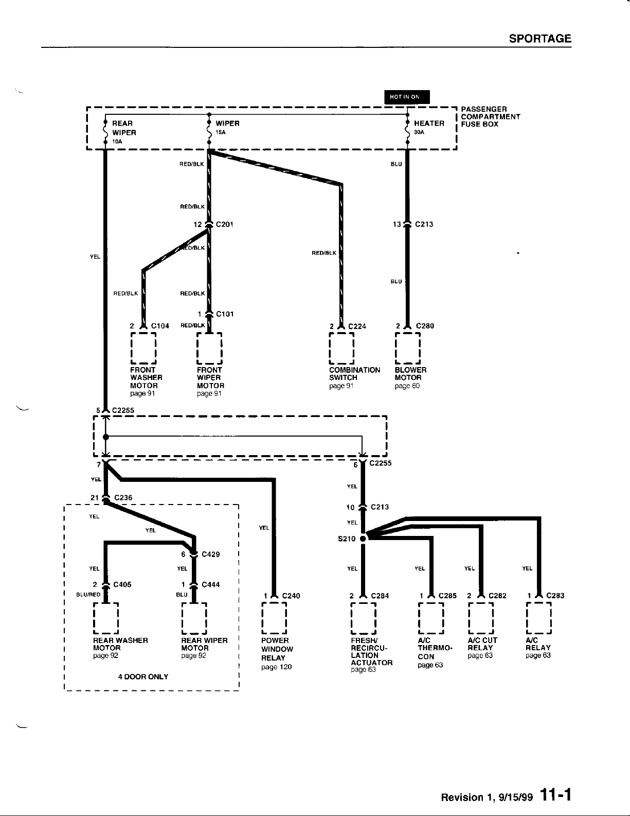
2 A C104
r-1
tl
ll
L-J
FRONT
WASHER
MOTOB
page
sA c225s
91
1
BEo/BLX
tt
ll
L-J
FRONT
WIPER
MOTOR
page
91
2
A, C224
tl
ll
L-J
COMBINATION
swtTcH
g1
page
HEATER
---J
2 A C2AO
r-1
tl
tl
L-J
BLOWER
MOTOA
page
60
SPORTAGE
PASSENGER
COMPARTMENT
FUSE BOX
L
7
2
c405
i
ll
tl
L-J
REAB WASHER
MOTOR
page
92
4 OOOR ONLY
BLU
10
YEL
1
C444
1 A C240
r-1
ll
ll
L-J
POWER
wtNoow
RELAY
page
120
1AC2a5 2 A C2a2
r-.lr-.t
tttl
tttl
L-J L-J
A./C A/C CUT
THERMO. RELAY
CON
page
63
page
63
I A C283
r-'t
tl
ll
L-J
A/C
RELAY
page
ffi
Revision
1,
9/15/99
1 1'1
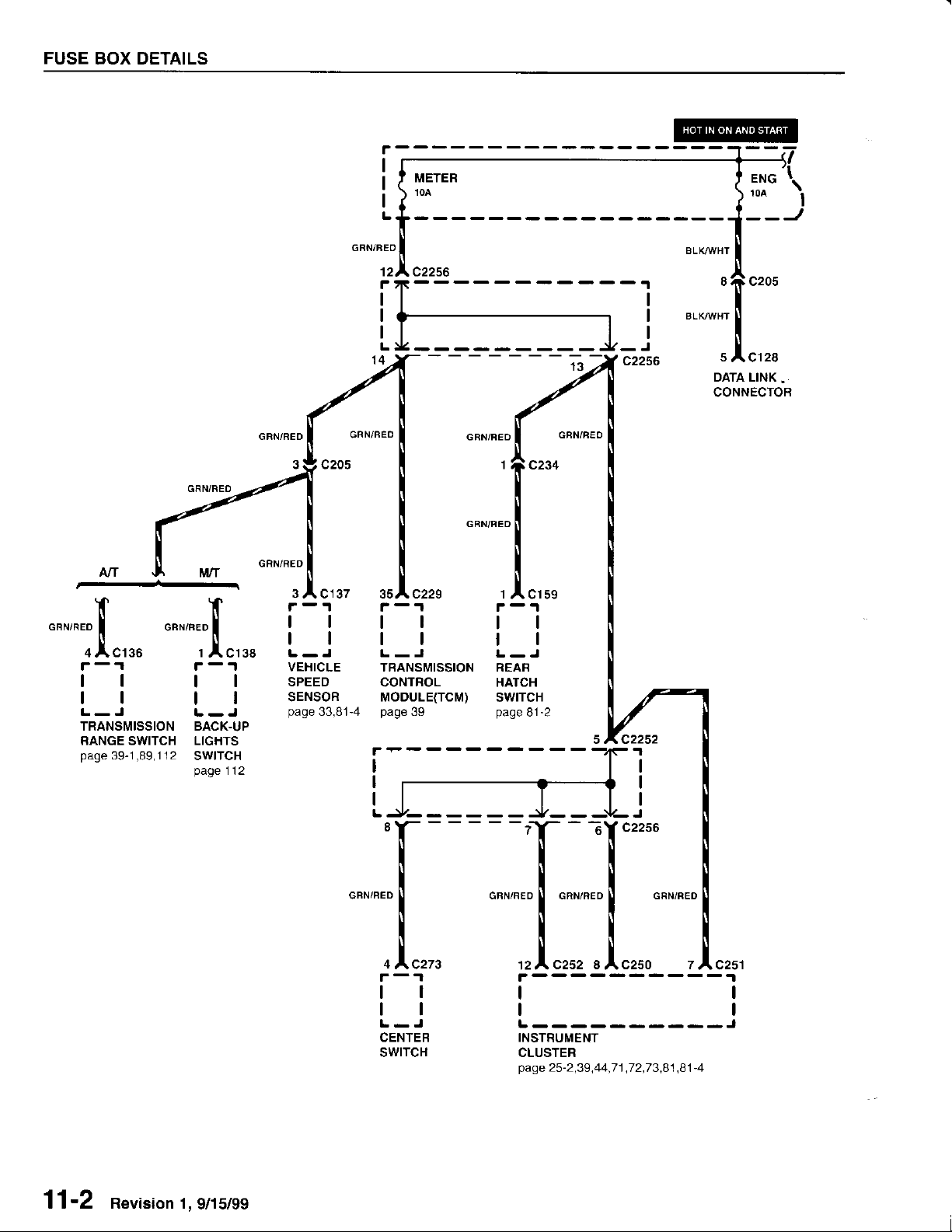
FUSE
BOX DETAILS
tl
VEHICLE
SPEED
SENSOR
page
33,81-4
GFN/NED
L-J
TBANSMISSION
CONTROL
MODULE(TCM)
page
39
4
4C273
r-1
ll
tl
L-J
CENTEB
swtTcH
1
A, Cl59
-T-.
c2256
,".o I o"n,".o
',,1,",u,
l!
tl
L----------J
INSTRUMENT
CLUSTER
page
,
25-2,39.44,71
.72,73,81 ,B
1
c251
-4
11'2 nevision 1,
9/15/99
 Loading...