

Kia Optima, Magnetis Bodyshop Manual

Body Shop Manual
mashinesoft.com
09120146259
FOREWORD
This Body Shop Manual illustrates body structures and
service procedures for the OPTIMA/MAGENTIS.
This manual illustrates the replacement of major body panels,
plastic parts, body dimensions, sealing treatment etc., in a
systematic manner which is necessary for effective and
lasting body repairs.
You are encouraged to become familiar with this manual
and understand each section in order to perform proper repair
procedures. Keep this manual in a convenient location so
that it is readily available.
All information in this manual including specifications,
data and illustrations is made based on the vehicles built at
the time the manual was printed.
Information regarding the removal/replacement of
components not specifically covered in this manual can be
found in the OPTIMA/MAGENTIS Service Manual.
Information regarding electrical harness routing/
connections, etc. can be found in the OPTIMA/MAGENTIS
Electrical T roubleshooting Manual.
The descriptions and specifications contained in this manual
were in effect at the time this manual was approved for
printing. Kia Motors Corporation reserves the right to
discontinue models at any time, or change specifications
or design without notice and without incurring obligation.
CONTENTS
Title Group
General Information
Body Construction
Body Dimensions
Body Panel Repair Procedure
Body Sealing Locations
Corrosion Protection
Body Modification Tools
Plastic Parts
GI
BC
BD
BP
BS
CP
BT
PP
Kia Motors Corporation
CAUTION :
Severe engine and transaxle damage may result from
the use of poor quality fuels and lubricants that do
not meet Kia specifications. You must always use
high quality fuels and lubricants that meet the
specifications described on the specification section
in the relevant group of the W orkshop Manual.
Copyright c 2005, Kia Motors Corporation
Printed in Korea, September 2005
Pub. No. : A2GB-EG58A (English)
All rights reserved. No part of this publication may be reproduced, stored in an y retrie val system or tr ansmitted in any
form or by any means without the prior written permission of Kia Motors Corporation.
SEOUL, KOREA

IMPORTANT SAFETY NOTICE
mashinesoft.com
09120146259
Proper service methods and repair procedures are essential for safe, reliable operation of all
motor vehicles as well as personal safety of the operator. The service procedures and
descriptions in this shop manual provide general directions for a service and repair.
Procedure, techniques, tools, and parts for service including the skill of the technician vary.
It is impossible to provide advice or caution as to each case in this manual.
Accordingly, anyone who intends to use a replacement part, service procedure, or tool, which is
not recommended by the vehicle manufacturer, must first assure thoroughly that neither their
personal safety nor the safe operation of the vehicle will be first jeopardized by the replacement
part, service procedure, or tool they select.
IN THIS MANUAL
WARNING :
CAUTION :
NOTE :
The following list contains some general WARNINGS that you should follow while working on a
vehicle.
Always wear safety glasses for eye protection.
Use safety stands whenever a procedure requires you to be under the vehicle.
Make sure that the ignition switch is always in the OFF position, unless otherwise required by
the procedure.
Set the parking brake when working on the vehicle. If you have an automatic transaxle, set in
park unless instructed otherwise for a specific operation
Place supporters against the front and rear surfaces of the tires to help prevent the vehicle
from moving
Operate the engine only in a well-ventilated area to avoid the danger of carbon monoxide
poisoning.
Keep yourself and your clothing away from moving parts when the engine is running,
especially the drive belts.
To prevent serious burns, avoid contact with hot metal parts such as the radiator, exhaust
manifold, tail pipe, catalytic converter and muffler.
Do not smoke while working on a vehicle.
To avoid injury, always remove rings, watches, loose hanging jewelry, and loose clothing
before beginning to work on a vehicle.
When it is necessary to work under the hood, keep hands and other objects clear of the
radiator fan blades! Your vehicle may be equipped with a cooling fan that may turn on, even
though the ignition switch is in the OFF position. For this reason care should be taken to
ensure that the radiator fan electric motor is completely disconnected when working under the
hood and the engine is not running.
Remind you to be especially careful in those areas where carelessness can
cause personal injury.
To prevent you from making errors that could damage the vehicle as well as
personal injury.
Gives you added information that will help you complete a particular procedure.

General
mashinesoft.com
09120146259
Information
FUNDAMENTAL PROCEDURES
VEHICLE PROTECTION..................................GI - 2
A WORD ABOUT SAFETY ...............................GI - 2
WELDING PROCEDURES ..............................GI - 3
BOD Y FRAME STRAIGHTENER.....................GI - 3
ELECTRICAL PROCEDURES ........................GI - 3
FOR BEST RESULTS
DISASSEMBLY.................................................GI - 4
PREPARATION OF ASSEMBLY.......................GI - 6
ASSEMBLY.......................................................GI - 7
RUSTPROOF TREA TMENT AFTER
ASSEMBLY.......................................................GI - 8
VEHICLE LIFT (2-SUPPORT TYPE) AND
SAFETY STAND POSITIONS
...................GI - 9
GI
JACK SUPPORT POSITIONS ..................GI - 10

GI-2 GENERAL INFORMATION
mashinesoft.com
09120146259
FUNDAMENT AL PR OCEDURES
VEHICLE PROTECTION
1. Cover the seats before performing any procedure to
keep them from getting dirty.
2. Cover all glasses, seats and mats with a heat resistant
cover when welding.
BVQGI6001
3. Protect moldings, garnishes and ornaments.
A WORD ABOUT SAFETY
1. Wear the appropriate safety equipment that is
necessary for the procedure being performed.
Safety glasses
Mask
Face shield
2. When welding or performing other procedures that
require the use of an open flame near the fuel tank,
disconnect and remove the tank and fuel pipe, and
cap the pipe to prevent fuel leakage.
Ear protectors
Gloves
Safety shoes
BVQGI6002
BVQGI6003
GENERAL INFORMATION GI-3
mashinesoft.com
09120146259
WELDING PROCEDURES
Observe the following tips when welding.
1. Wear appropriate eye protection.
2. Carefully follow the manufacturers operating
instructions for the welding machine you are using.
3. Do not weld, smoke or allow open flames around
volatile chemicals, cleaners or solvents or in any area
where they have just been used.
BODY FRAME STRAIGHTENER
When using a frame straightener, do not enter the area
where the body is being straightened by the chain.
ELECTRICAL PROCEDURES
1. Disconnect the negative battery terminal.
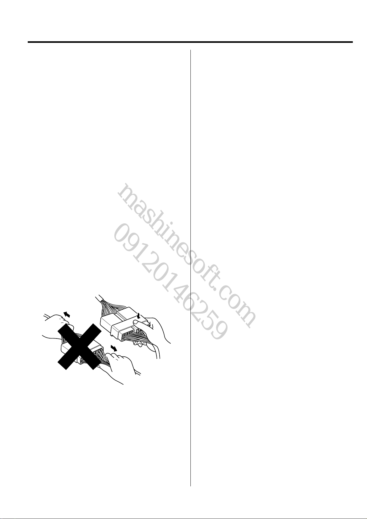
2. Do not pull on wires when disconnecting electrical
connectors. Be careful to hold the connector itself when
disconnecting it.
3. Insert the connector until it "licks" when connecting
the connector.
4. Handle all electrical components with care.
BVQGI6004
GI-4 GENERAL INFORMATION
mashinesoft.com
09120146259
FOR BEST RESUL TS
DISASSEMBLY
Measuring dimensions before beginning
Measure the dimensions of the damaged area according to the body dimension drawings before disassembling and repairing.
Adjust dimensions with body frame adjuster if deformed.
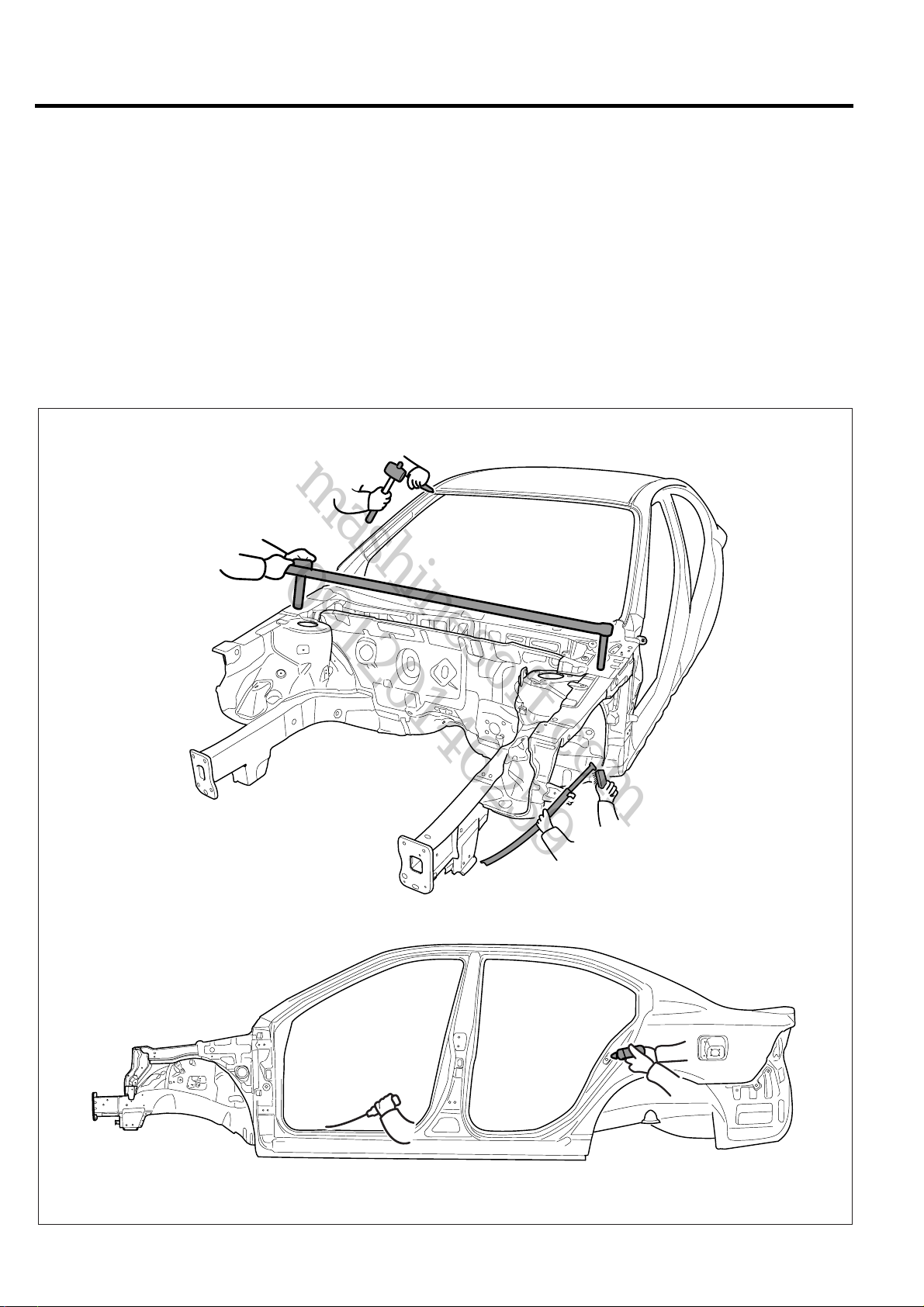
Selecting cutting area
Select a cutting area that is easily accessible and that is prone to the least amount of distortion when welding.
Select an area that would allow the new part to overlap repair area by 1.2~2.0 in (30~50 mm).
Protecting body from damage
Secure the body with clamps and jacks to prevent damage to the body when working on it.
BMGGI6005
GENERAL INFORMATION GI-5
mashinesoft.com
09120146259
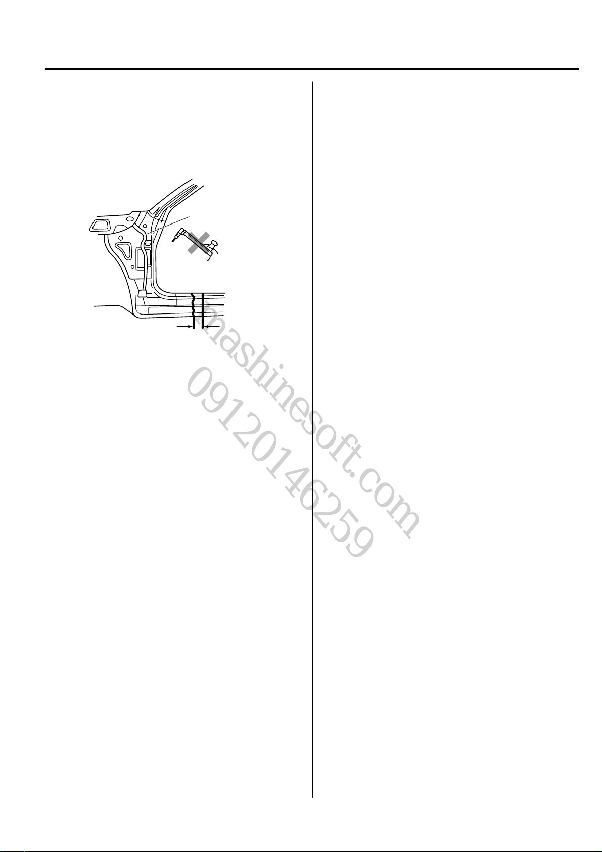
Disassembling related parts
Use caution when removing body molding and trim from
the area to be worked.
Apply masking tape where needed to prevent damage to
the part being removed or to the vehicle body.
Before starting repairs, check if pipes, hoses or electrical
components are present near damaged area.
Wire harness
Repair work area
Cutting area
BVQGI6006
GI-6 GENERAL INFORMATION
mashinesoft.com
09120146259
PREPARATION OF ASSEMBLY
Applying spot sealer
Remove paint from the surf ace of new parts and body to be spot welded, and apply spot sealer for rustproofing.
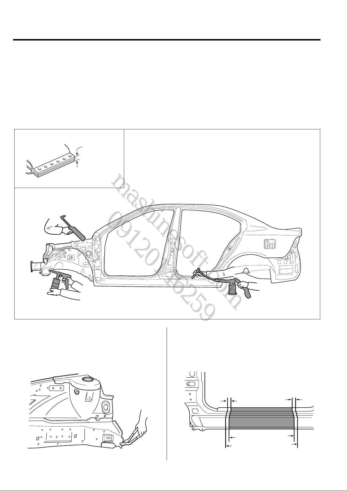
Selecting a welding method
If the thickness of the area to be welded with the panels overlapped is greater than 0.1 in (3 mm), do plug welding using a
carbon arc welding machine.
Protecting body from damage
Secure the body with clamps and jacks to prevent damage to the body when working on it.
Thicker than
0.1 in (3mm)
Machining holes for plug welding
Drill a hole of approximately 0.2~0.24 in (5~6 mm) in
diameter in those areas which are not suitable for spot
welding.
BVQGI6008
BMGGI6007
Adjusting a new part
The new part should be cut larger than the repair area,
overlapping the repair area by 1.2~2.0 in (30~50 mm).
1.2~2.0 in
(30~50 mm)
Overlap
body side to modify
new part to modify
1.2~2.0 in
(30~50 mm)
Overlap
BVQGI6009
GENERAL INFORMATION GI-7
mashinesoft.com
09120146259
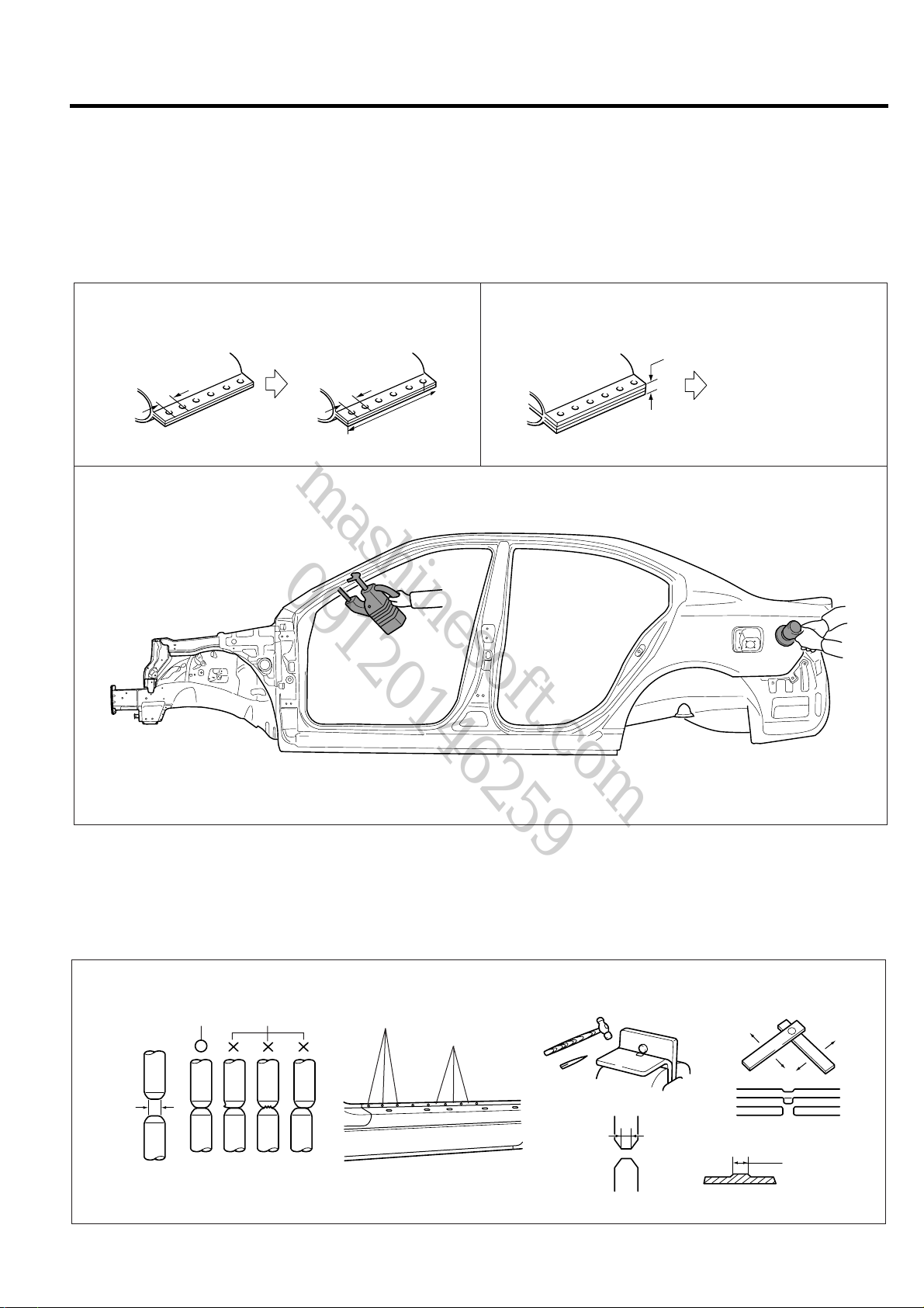
ASSEMBLY
Measuring dimensions before welding
When assembling a new part, assemble it according to the body dimensions given in Section 31, and start welding after
checking the gaps with nearby parts.
Caution when welding
The number of welding points should be determined based on the criteria below:
Spot welding Plug welding
Pitch:
2.0 in (50 mm)
Old part
Increase the number of
spot welds by 30%.
Pitch:
1.4 in (35 mm)
Repair part
Pitch: Same number of
welds as original part.
Repair part
more than
0.1 in (3 mm)
Caution when spot welding
The tip of the spot welding machine should be maintained to a minimum of 0.1 in (3 mm) because it greatly affects welding
strength. When possib le, spot welding should be done between the existing spot w elded points.
Before and after spot welding, weld a test piece(test pin) of the same material as the body panel, and check the welding
strength.
Good
0.1 in
(3 mm)
No good
Existing welded spots
New welded spots
Using a hammer and a chisel
0.1 in
(3 mm)
Center
diameter
BMGGI6010
Using a test piece(test pin)
Nugget diameter
to be 4/5 of chip
diameter
BVQGI6011
GI-8 GENERAL INFORMATION
mashinesoft.com
09120146259
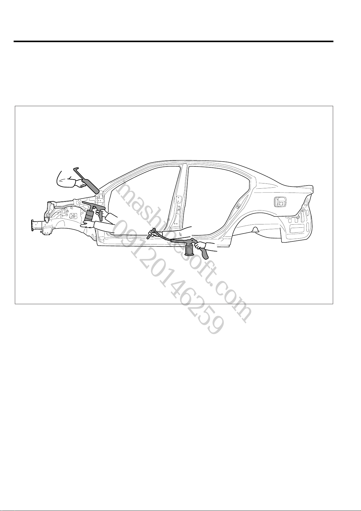
RUSTPROOF TREATMENT AFTER ASSEMBLY
Body sealing
Apply body sealer where necessary.
Applying rustproof material
Apply rustproofing material(wax, oil, etc.) behind welded area.
Applying undercoat
Apply undercoat on the body where necessary.
BMGGI6012
GENERAL INFORMATION GI-9
mashinesoft.com
09120146259
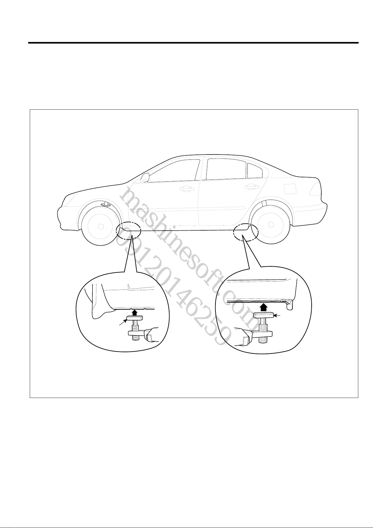
VEHICLE LIFT (2-SUPPORT TYPE) AND SAFETY STAND POSITIONS
1. Place the lift blocks under the support points as shown in the illustration
2. Raise the hoist a few inches and rock the v ehicle to be sure it is firmly supported.
3. Raise the hoist to full height to inspect the lift points for secure support.
Lift Block
[Front]
Lift Block
[Rear]
BMGGI6013
GI-10 GENERAL INFORMATION
mashinesoft.com
09120146259
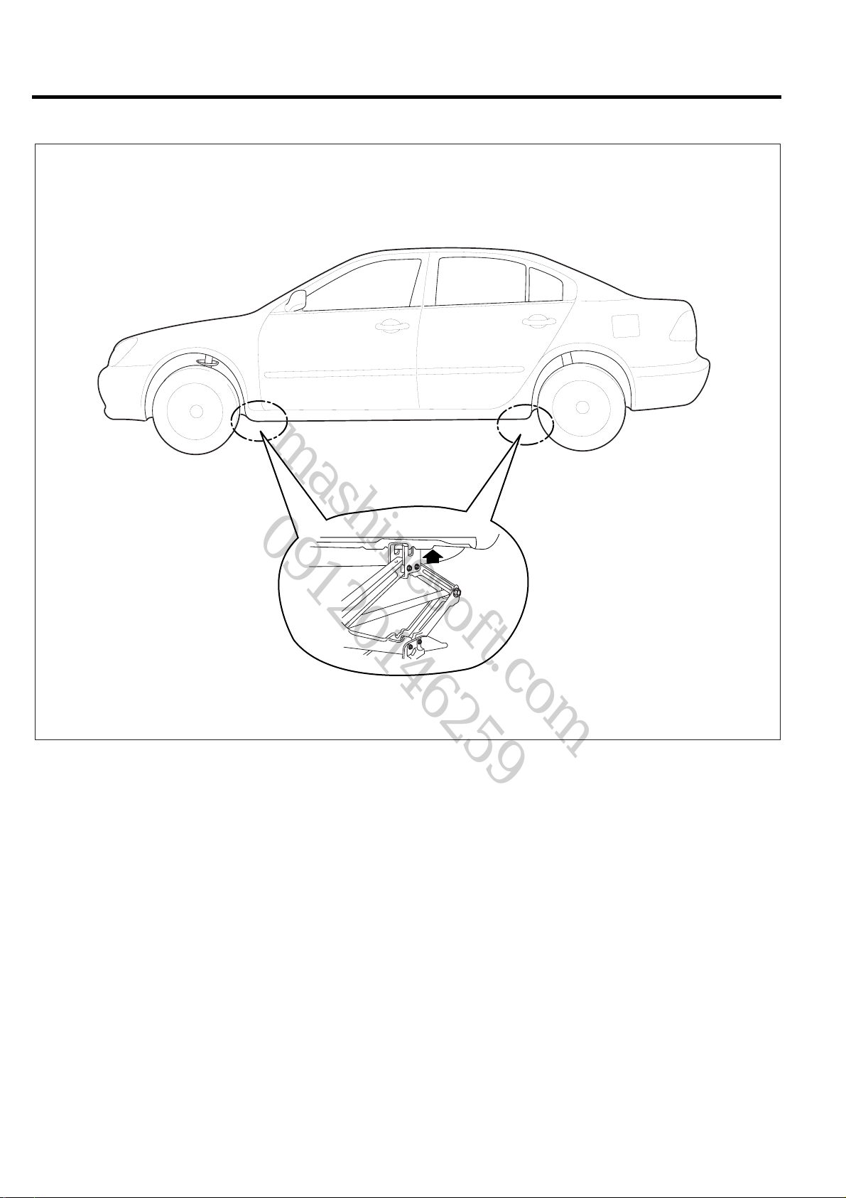
JACK SUPPORT POSITIONS
BMGGI6013

Body
mashinesoft.com
09120146259
Construction
BODY COMPONENTS .................................BC - 2
ZINC-GALVANIZED STEEL PANELS ....BC - 4
HIGH STRENGTH STEEL PANELS .......BC - 6
BC
BC-2 BODY CONSTRUCTION
mashinesoft.com
09120146259
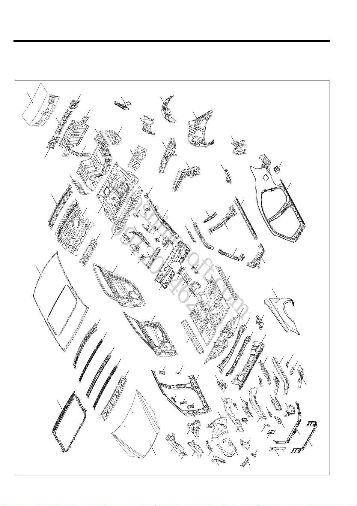
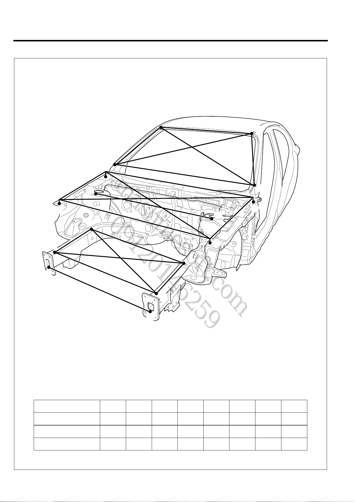
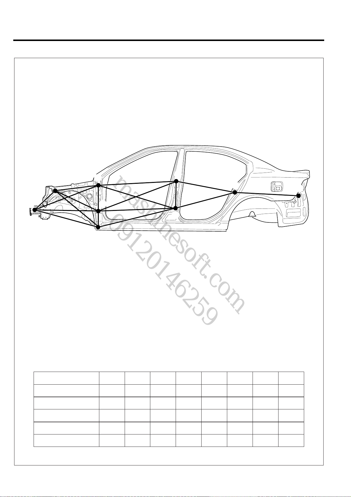
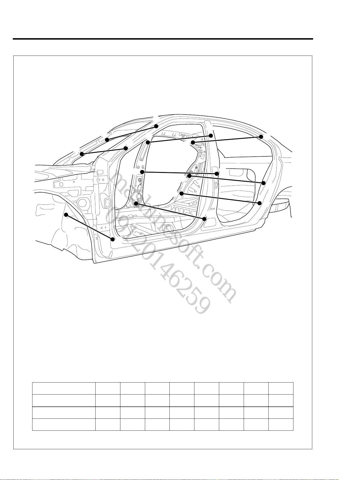
BOD Y COMPONENTS
Body construction will sometimes differ depending on specifications and country of destination. Theref ore, please k eep in
mind that the information contained herein is based on vehicles for general destination.
72
64
76
79
74
81
76
75
77
73
80
82
78
69
84
92
55
98
81
83
99
100
91
56
103
97
90
101
94
96
54
85
104
52
102
93
95
86
87
47
53
88
46
51
89
62
44
49
50
43
63
42
45
61
57
48
40
41
4
59
68
67
66
65
70
71
39
58
60
63
27
38
34
59
37
36
35
7
9
10
17
6
8
11
22
16
18
19
14
5
12
28
15
26
30
24
20
21
13
33
25
32
31
29
23
2
1
3
BMGBC6001

BODY CONSTRUCTION BC-3
mashinesoft.com
09120146259
1. Radiator support lower member
2. Radiator support upper member
3. Radiator support center member
4. Fender panel
5. Fender apron inner panel
6. Front shock absorber housing panel
7. Shock absorber cover
8. Shock absorber housing reinforcement
9. Fender apron upper outer panel
10. Fender apron upper inner panel
11. Fender apron front upper reinforcement
12. Fender apron front lower reinforcement
13. Transaxle side mounting bracket
14. Engine mounting support
15. Front side inner member
16. Front side member inner reinforcement
17. Front side outer member
18. Engine mounting rear bracket
19. Engine mounting front bracket
20. Front end module mounting reinforcement
21. Front end module mounting bracket
22. Front side member outer extension
23. Front side member outer front extension
24. Sub frame mounting front support
25. Front side rear lower member
26. Front side member rear lower reinforcement
27. Front side inner rear reinforcement
28. Front side rear upper reinforcement
29. Front side member rear lower extension
30. Side sill inner front extension
31. Sub frame rear mounting bracket
32. Sub frame rear mounting reinforcement
33. Sub frame rear mounting support
34. Side inner panel
35. Cowl cross member front bracket
36. Cowl cross member rear bracket
37. Front pillar upper extension
38. Front seatbelt reel mounting bracket
39. Center pillar inner reinforcement
40. Side outer panel
41. Front pillar outer lower reinforcement
42. Front pillar outer upper reinforcement
43. Center pillar outer reinforcement
44. Center pillar outer upper reinforcement
45. Side sill outer reinforcement
46. Roof side outer reinforcement
47. Roof side outer rail
48. Fuel filler mounting
49. Side outer rear extension
50. Rear combination lamp housing panel
51. Quarter inner lower panel
52. Quarter inner upper panel
53. Quarter panel reinforcement
54. Wheel house inner panel
55. Rear package tray side front panel
56. Rear package tray side rear panel
57. Cowl top upper reinforcement
58. Cowl top lower reinforcement
59. Shock absorber housing gusset assembly
60. Cowl top panel assembly
61. Dash panel assembly
62. Center floor panel assembly
63. Side sill inner panel
64. Roof panel
65. Roof front rail assembly
66. Roof center NO.1 rail
67. Roof center rail assembly
68. Roof center NO.3 rail
69. Roof rear rail assembly
70. Sun roof reinforcement ring
71. Hood panel assembly
72. Trunk lid panel assembly
73. Back panel
74. Rear transverse member
75. Trunk lid striker suppor t
76. Rear transverse extension
77. Rear package tray center panel
78. Rear package tray front lower member
79. Rear window opening outer frame
80. Rear floor rear panel assembly
81. Rear floor side panel assembly
82. Rear floor front panel
83. Rear seat mounting bracket
84. Rear floor front extension
85. Rear floor front cross member assembly
86. Rear floor front cross reinforcement
87. Center floor side member rear extension
88. Rear floor front filler assembly
89. Center floor side member rear extension assembly
90. Rear floor center cross member assembly
91. Rear floor center cross center reinforcement
92. Rear door panel assembly
93. Rear floor center cross member extension
94. Rear suspension mounting upper bracket
95. Rear floor side member assembly
96. Rear floor side rear member assembly
97. Rear suspension spring sheet reinforcement
98. Trailing arm mounting upper bracket
99. Rear tie down reinforcement
100. Side sill inner rear panel
101. Trailing arm mounting upper bracket assembly
102. Side sill inner rear reinforcement
103. Trailing arm mounting lower bracket assembly
104. Front door panel assembly
BC-4 BODY CONSTRUCTION
mashinesoft.com
09120146259
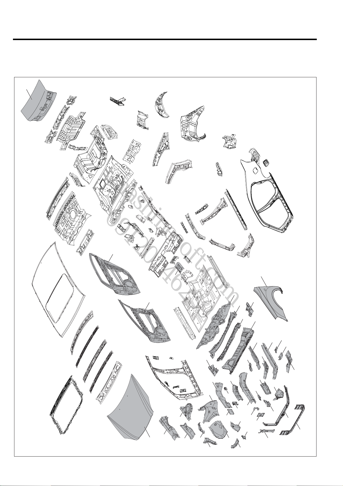
ZINC-GAL VANIZED STEEL PANELS
Becavanized steel panel has excellent resistance, it tis used in areas which have a high possibility of painting deficiency
below.
72
92
104
71
12
58
28
15
13
20
24
59
21
60
27
30
4
33
25
32
26
31
29
23
2
1
3
BMGBC6002
87
61
57
59
11
22
16
18
19
14
5
17
6
7
9
10
8

BODY CONSTRUCTION BC-5
mashinesoft.com
09120146259
1. Radiator support lower member
2. Radiator support upper member
3. Radiator support center member
4. Fender panel
5. Fender apron inner panel
6. Front shock absorber housing panel
7. Shock absorber cover
8. Shock absorber housing reinforcement
9. Fender apron upper outer panel
10. Fender apron upper inner panel
11. Fender apron front upper reinforcement
12. Fender apron front lower reinforcement
13. Transaxle side mounting bracket
14. Engine mounting support
15. Front side inner member
16. Front side member inner reinforcement
17. Front side outer member
18. Engine mounting rear bracket
19. Engine mounting front bracket
20. Front end module mounting reinforcement
21. Front end module mounting bracket
22. Front side member outer extension
23. Front side member outer front extension
24. Sub frame mounting front support
25. Front side rear lower member
26. Front side member rear lower reinforcement
27. Front side inner rear reinforcement
28. Front side rear upper reinforcement
29. Front side member rear lower extension
30. Side sill inner front extension
31. Sub frame rear mounting bracket
32. Sub frame rear mounting reinforcement
33. Sub frame rear mounting support
34. Side inner panel
35. Cowl cross member front bracket
36. Cowl cross member rear bracket
37. Front pillar upper extension
38. Front seatbelt reel mounting bracket
39. Center pillar inner reinforcement
40. Side outer panel
41. Front pillar outer lower reinforcement
42. Front pillar outer upper reinforcement
43. Center pillar outer reinforcement
44. Center pillar outer upper reinforcement
45. Side sill outer reinforcement
46. Roof side outer reinforcement
47. Roof side outer rail
48. Fuel filler mounting
49. Side outer rear extension
50. Rear combination lamp housing panel
51. Quarter inner lower panel
52. Quarter inner upper panel
53. Quarter panel reinforcement
54. Wheel house inner panel
55. Rear package tray side front panel
56. Rear package tray side rear panel
57. Cowl top upper reinforcement
58. Cowl top lower reinforcement
59. Shock absorber housing gusset assembly
60. Cowl top panel assembly
61. Dash panel assembly
62. Center floor panel assembly
63. Side sill inner panel
64. Roof panel
65. Roof front rail assembly
66. Roof center NO.1 rail
67. Roof center rail assembly
68. Roof center NO.3 rail
69. Roof rear rail assembly
70. Sun roof reinforcement ring
71. Hood panel assembly
72. Trunk lid panel assembly
73. Back panel
74. Rear transverse member
75. Trunk lid striker suppor t
76. Rear transverse extension
77. Rear package tray center panel
78. Rear package tray front lower member
79. Rear window opening outer frame
80. Rear floor rear panel assembly
81. Rear floor side panel assembly
82. Rear floor front panel
83. Rear seat mounting bracket
84. Rear floor front extension
85. Rear floor front cross member assembly
86. Rear floor front cross reinforcement
87. Center floor side member rear extension
88. Rear floor front filler assembly
89. Center floor side member rear extension assembly
90. Rear floor center cross member assembly
91. Rear floor center cross center reinforcement
92. Rear door panel assembly
93. Rear floor center cross member extension
94. Rear suspension mounting upper bracket
95. Rear floor side member assembly
96. Rear floor side rear member assembly
97. Rear suspension spring sheet reinforcement
98. Trailing arm mounting upper bracket
99. Rear tie down reinforcement
100. Side sill inner rear panel
101. Trailing arm mounting upper bracket assembly
102. Side sill inner rear reinforcement
103. Trailing arm mounting lower bracket assembly
104. Front door panel assembly
BC-6 BODY CONSTRUCTION
mashinesoft.com
09120146259
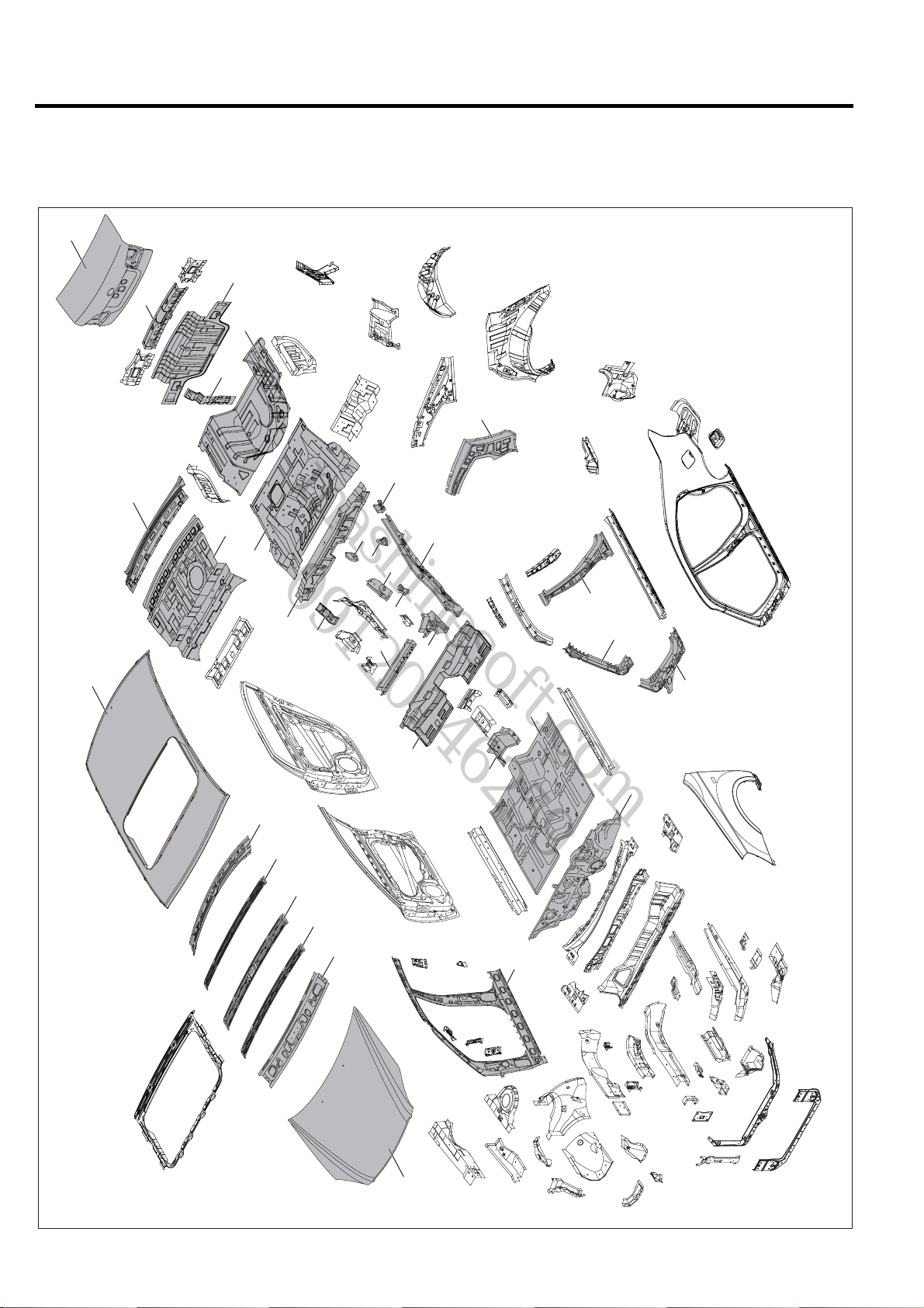
HIGH STRENGTH STEEL P ANELS
Because high strength steel panel has excellent resistance, it is used in areas which have a high posibility of painting
deficiency below.
72
73
74
80
75
53
96
79
77
82
84
98
64
69
68
67
66
103
97
90
65
95
101
94
93
85
88
43
42
41
62
61
34
71
BMGBC6003

BODY CONSTRUCTION BC-7
mashinesoft.com
09120146259
1. Radiator support lower member
2. Radiator support upper member
3. Radiator support center member
4. Fender panel
5. Fender apron inner panel
6. Front shock absorber housing panel
7. Shock absorber cover
8. Shock absorber housing reinforcement
9. Fender apron upper outer panel
10. Fender apron upper inner panel
11. Fender apron front upper reinforcement
12. Fender apron front lower reinforcement
13. Transaxle side mounting bracket
14. Engine mounting support
15. Front side inner member
16. Front side member inner reinforcement
17. Front side outer member
18. Engine mounting rear bracket
19. Engine mounting front bracket
20. Front end module mounting reinforcement
21. Front end module mounting bracket
22. Front side member outer extension
23. Front side member outer front extension
24. Sub frame mounting front support
25. Front side rear lower member
26. Front side member rear lower reinforcement
27. Front side inner rear reinforcement
28. Front side rear upper reinforcement
29. Front side member rear lower extension
30. Side sill inner front extension
31. Sub frame rear mounting bracket
32. Sub frame rear mounting reinforcement
33. Sub frame rear mounting support
34. Side inner panel
35. Cowl cross member front bracket
36. Cowl cross member rear bracket
37. Front pillar upper extension
38. Front seatbelt reel mounting bracket
39. Center pillar inner reinforcement
40. Side outer panel
41. Front pillar outer lower reinforcement
42. Front pillar outer upper reinforcement
43. Center pillar outer reinforcement
44. Center pillar outer upper reinforcement
45. Side sill outer reinforcement
46. Roof side outer reinforcement
47. Roof side outer rail
48. Fuel filler mounting
49. Side outer rear extension
50. Rear combination lamp housing panel
51. Quarter inner lower panel
52. Quarter inner upper panel
53. Quarter panel reinforcement
54. Wheel house inner panel
55. Rear package tray side front panel
56. Rear package tray side rear panel
57. Cowl top upper reinforcement
58. Cowl top lower reinforcement
59. Shock absorber housing gusset assembly
60. Cowl top panel assembly
61. Dash panel assembly
62. Center floor panel assembly
63. Side sill inner panel
64. Roof panel
65. Roof front rail assembly
66. Roof center NO.1 rail
67. Roof center rail assembly
68. Roof center NO.3 rail
69. Roof rear rail assembly
70. Sun roof reinforcement ring
71. Hood panel assembly
72. Trunk lid panel assembly
73. Back panel
74. Rear transverse member
75. Trunk lid striker suppor t
76. Rear transverse extension
77. Rear package tray center panel
78. Rear package tray front lower member
79. Rear window opening outer frame
80. Rear floor rear panel assembly
81. Rear floor side panel assembly
82. Rear floor front panel
83. Rear seat mounting bracket
84. Rear floor front extension
85. Rear floor front cross member assembly
86. Rear floor front cross reinforcement
87. Center floor side member rear extension
88. Rear floor front filler assembly
89. Center floor side member rear extension assembly
90. Rear floor center cross member assembly
91. Rear floor center cross center reinforcement
92. Rear door panel assembly
93. Rear floor center cross member extension
94. Rear suspension mounting upper bracket
95. Rear floor side member assembly
96. Rear floor side rear member assembly
97. Rear suspension spring sheet reinforcement
98. Trailing arm mounting upper bracket
99. Rear tie down reinforcement
100. Side sill inner rear panel
101. Trailing arm mounting upper bracket assembly
102. Side sill inner rear reinforcement
103. Trailing arm mounting lower bracket assembly
104. Front door panel assembly

Body
mashinesoft.com
09120146259
Dimensions
GENERAL
MEASUREMENT METHOD .......................BD - 2
PROJECTED DIMENSIONS ............................BD - 2
ACTUAL-MEASUREMENT DIMENSIONS......BD - 3
MEASUREMENT POINT..................................BD - 3
FRONT BODY .................................................BD - 4
SIDE BODY ......................................................BD - 6
INTERIOR A .....................................................BD - 8
INTERIOR B .....................................................BD - 10
INTERIOR C .....................................................BD - 12
REAR BODY ....................................................BD - 14
UNDER BODY
(PROJECTED DIMENSIONS)
UNDER BODY
(STRAIGHT-LINE DIMENSIONS)
.........................................................BD - 2
...................BD - 16
............BD - 18
BD
BD-2 BODY DIMENSIONS
mashinesoft.com
09120146259
GENERAL
1. Basically, all measurements in this manual are taken
with a tracking gauge.
2. When a measuring tape is used, check to be sure there
is no elongation, twisting or bending.
3. For measuring dimensions, both projected dimension
and actual-measurement dimension are used in this
manual.
MEASUREMENT METHOD
PROJECTED DIMENSIONS
1. These are the dimensions measured when the
measurement points are projected into the reference
plane, and are the reference dimensions used for body
alterations.
2. If the length of the tracking gauge probes are
adjustable, make the measurement by lengthening one
probe by the amount equivalent to the difference in
height of the two surfaces.
Height
Projected Dimension
BMCBD6001

BODY DIMENSIONS BD-3
N
mashinesoft.com
09120146259
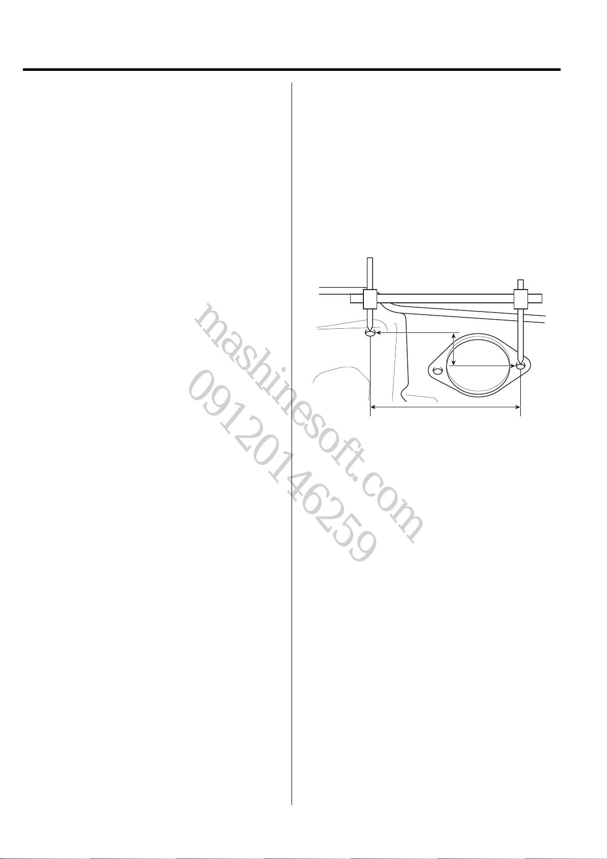
ACTUAL-MEASUREMENT DIMENSIONS
1. These dimensions indicate the actual linear distance
between measurement points, and are the reference
dimensions for use if a tracking gauge is used for
measurement.
2. Measure by first adjusting both probes to the same
length (A=A')
CAUTIO
Check the probes and gauge itself to make sure
there is no free play.
A
Actually-Measured Dimension
A'
MEASUREMENT POINT
1. Measurements should be taken at the hole center.
Hole Center
BMCBD6003
BMCBD6002
BD-4 BODY DIMENSIONS
mashinesoft.com
09120146259
FRONT BODY
H
H'
G
B
C
A
D
E
D'
F
E'
F'
* These dimensions indicated in this figure are actual-measurement dimensions.
G'
B'
C'
A'
BMGBD6001
Point symbol
Length(mm)
Point symbol
Length(mm)
A-A'
1416
D'-E'
390
A-B
709
D'-E
1054
A-B'
1660
E-E'
980
B-B'
1585
F-F'
984
C-C'
1178
G-G'
1505
D-D'
978
G-H
747
D-E
390
G-H'
1476
D-E'
1054
H-H'
1077
BODY DIMENSIONS BD-5
mashinesoft.com
09120146259
A,A'
BMGBD6002
Front end module mounting hole
(ø9)
D
BMGBD6005
Engine bracket mounting hole
(ø15)
B,B'
BMGBD6003
Hood hinge mounting hole (ø11)
D'
BMGBD6006
Transaxle bracket mounting hole
(ø15)
G,G'
C,C'
BMGBD6004
Tooling hole (ø11)
E,E'
BMGBD6007
Wiring mounting hole (S7x12)
H,H'
F,F'
Tooling hole (ø8)
BMGBD6007A
Front side outer edge
BMGBD6008
BMGBD6009
Front roof edge
BD-6 BODY DIMENSIONS
mashinesoft.com
09120146259
SIDE BODY
B
A
* These dimensions indicated in this figure are actual-measurement dimensions.
C
D
E
F
H
G
K
BMGBD6101
Point symbol
Length(mm)
Point symbol
Length(mm)
Point symbol
Length(mm)
A-B
568
C-F
1103
G-H
895
A-C
1217
C-G
1128
H-K
935
A-D
1164
D-E
308
A-E
1117
D-F
1174
B-C
726
D-G
1082
B-D
788
E-G
1196
B-E
889
F-G
365
C-D
360
F-H
850

BODY DIMENSIONS BD-7
mashinesoft.com
09120146259
B
C
A
BMGBD6102
BMGBD6103
BMGBD6104
Tooling hole (ø10)
D
BMGBD6105
Front door lower hinge mounting
hole (ø13)
Wiring mounting hole (S7x12)
E
BMGBD6105A
Fender mounting hole (ø10)
H
Front door upper hinge mounting
hole (ø13)
F
BMGBD6106
Rear door upper hinge mounting
hole (ø13)
K
G
BMGBD6107
Rear door lower hinge mounting
hole (ø13)
Door switch mounting hole (ø17)
BMGBD6108
BMGBD6109
Rear bumper mounting hole
(S6.5x8)
BD-8 BODY DIMENSIONS
mashinesoft.com
09120146259
INTERIOR A
A'
A
B'
B
D
G
D'
G'
E
H
F
C
C'
* These dimensions indicated in this figure are actual-measurement dimensions.
K
E'
F'
H'
K'
BMGBD6201
Point symbol
Length(mm)
Point symbol
Length(mm)
A-A'
1222
K-K'
1457
B-B' C-C' D-D' E-E' F-F' G-G' H-H'
1389 1450 1235 1429 1423 1205 1456
BODY DIMENSIONS BD-9
mashinesoft.com
09120146259
B,B'
A,A'
BMGBD6202
Front trim mounting hole (ø8.5)
D,D'
BMGBD6205
Front seatbelt mounting hole
(ø16)
BMGBD6203
Front cab mounting hole (ø6.6)
E,E'
BMGBD6206
Center pillar lower trim mounting
hole (ø8.5)
C,C'
BMGBD6204
Front cowl side trim mounting
hole (ø8.5)
F,F'
BMGBD6207
Front seatbelt retractor mounting
hole (ø12.2)
H,H'
G,G'
BMGBD6208
Cab guide bracket mounting hole
(ø6.6)
Rear door switch mounting hole
BMGBD6209
(ø17)
K,K'
BMGBD6210
Tooling hole (ø10)
BD-10 BODY DIMENSIONS
mashinesoft.com
09120146259
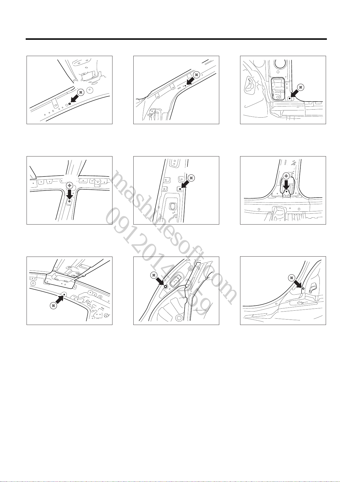
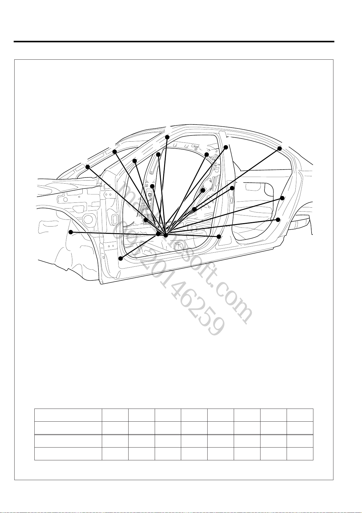
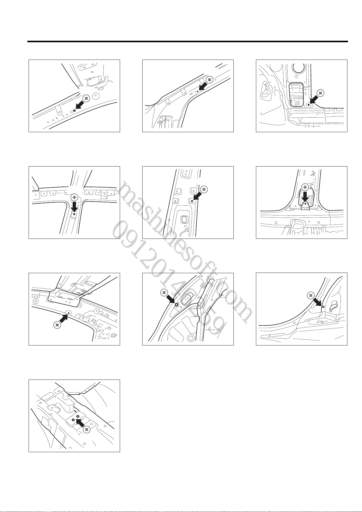
INTERIOR B
A'
F'
D'
G'
E'
H'
K'
BMGBD6301
A
B
C
C'
B'
F
D
E
M
M'
G
H
K
* These dimensions indicated in this figure are actual-measurement dimensions.
Point symbol
Length(mm)
Point symbol
Length(mm)
M-A'
1111
M-K'
1244
M-B' M-C' M-D' M-E' M-F' M-G' M-H'
1147 1021 1144 927 738 1565 1393
BODY DIMENSIONS BD-11
mashinesoft.com
09120146259
B,B'
A,A'
BMGBD6202
Front trim mounting hole (ø8.5)
D,D'
BMGBD6205
Front seatbelt mounting hole
(ø16)
BMGBD6203
Front cab mounting hole (ø6.6)
E,E'
BMGBD6206
Center pillar lower trim mounting
hole (ø8.5)
C,C'
BMGBD6204
Front cowl side trim mounting
hole (ø8.5)
F,F'
BMGBD6207
Front seatbelt retractor mounting
hole (ø12.2)
H,H'
G,G'
BMGBD6208
Cab guide bracket mounting hole
(ø6.6)
Rear door switch mounting hole
M,M'
BMGBD6302
Brake lever mounting hole (ø9)
BMGBD6209
(ø17)
K,K'
BMGBD6210
Tooling hole (ø10)
 Loading...