

Page 1
Point
Reference
DANGER
NOTICE
DANGER
DANGER
DANGER
96M12530
Dedicated Safety Relay
for the GL-R
GL-T11R
Instruction Manual
Introduction
This instruction manual describes handling, operation, and precautionary
information for the GL-T11R Safety Relay dedicated for use with the GL-R
Series Safety Light Curtain. Read this instruction manual thoroughly along
with the GL-R instruction manual and user manual before operating the
GL-T11R in order to ensure the optimum performance and functionality of
the GL-R and GL-T11R. Keep this manual readily available for reference.
Ensure that the end user of this product receives this manual.
This manual is the original instruction manual.
The GL-T11R can also be used with GL-S Series Safety Light Curtains, but
in this situation there are limitations on the functions that can be used.
Carefully read both the GL-S instruction manual and this instruction
manual to ensure that you fully understand the function limitations before
using this product.
Hereinafter, both the GL-R Series and GL-S Series of safety light curtains
are referred to as GL.
Safety Precautions
General Precautions
• You must verify that the GL-T11R is operating correctly in terms
of functionality and performance before starting the machine.
• KEYENCE does not guarantee the functions and performance
of the GL-T11R if it is used in a manner that differs from the
GL-T11R specifications described in this instruction manual or
if the GL-T11R is modified by the customer.
•
When using the GL-T11R to protect machine operators against a
hazard or hazardous zone or using the GL-T11R as a safety component for any purpose, always follow the applicable requirements of the laws, rules, regulations and standards in the country
or region where the GL-T11R is used. For such regulations, you
should make direct contact with the regulatory agency responsible for occupational safety and health in your country or region.
• Depending on the type of machine on which the GL-T11R is to
be installed, there may be special safety regulations related to
the use, installation, maintenance, and operation of the safety
component, and such safety regulations must be fulfilled. The
responsible personnel must install the GL-T11R in strict compliance with such safety regulations.
•
The responsible personnel must do the training to the assigned
personnel for the correct use, installation, maintenance, and
operation of the GL-T11R. "Machine operators" refers to personnel who have received appropriate training from the responsible
personnel and are qualified to operate the machine correctly.
•
Machine operators must have specialized training for the GL-T11R,
and they must understand and fulfill the safety regulations in the
country or region in which they are using the GL-T11R.
• When the GL-T11R fails to operate, machine operators must
immediately stop the use of the machine and the GL-T11R and
report this fact to the responsible personnel.
•
The GL-T11R is designed with the assumption that it would be correctly installed and operated in accordance with the installation
and operation procedures described in this instruction manual.
You must perform an appropriate installation of the GL-T11R after
conducting a sufficient risk assessment for the target machine.
• When disposing of the GL-T11R, make sure to follow requirements, rules, codes, regulations and laws regarding industrial
wastes in countries or regions where the GL-T11R is used.
• The GL-T11R should be processed as an industrial waste product when being disposed.
Safety Headings
This instruction manual uses the following symbols that alert you to important safety information. Strict adherence to the instructions next to these
heading is required at all times.
It indicates a hazardous situation which, if not avoided, will
result in death or serious injury.
It indicates a situation which, if not avoided, could result in
product damage as well as property damage.
It indicates additional information on proper operation.
It indicates tips for better understanding or useful information.
Indicates reference pages in this or another manual.
Precaution on Use
■ Operators
• In order to operate the GL-T11R correctly, the responsible personnel and machine operators must follow all procedures
described in this instruction manual.
• No person other than the responsible personnel and machine
operators should be allowed to install or test the GL-T11R.
• When performing electrical wiring, always fulfill the electrical
standards and regulations for the country or region in which
the GL-T11R is used.
■ Installation environment
• The GL-T11R is not designed to be explosion-proof. Never use it
in the presence of flammable or explosive gases or elements.
•
When using the GL-T11R in the presence of substances, such as heavy
smoke, particulate matter, or corrosive chemical agents, confirm that
such substances do not induce deterioration in product quality.
• Be sure to confirm absolutely that there is nobody in the
hazardous zone, before the interlock is released (i.e. the
machine system restarts) by the interlock reset mechanism.
Failure to follow this warning may result in significant harm to
the machine operators, including serious injury or death.
• Interlock reset mechanisms (such as switches) must be
installed so that the whole hazardous zone can be checked by
the responsible personnel. Interlock reset mechanisms should
not be accessible from within the hazardous zone.
• Use the GL-T11R within an enclosure of IP54 or higher.
• Ensure there is space around the unit for ventilation.
• Do not install the GL-T11R in the locations listed below:
• Locations with high humidity and a risk of condensation
• Locations where water will splash onto the GL-T11R
• Locations where there are corrosive gases
• Locations where any flammable gases or explosive gases
exist
• Locations where the GL-T11R may be directly subjected to
vibration or impact
• Locations where strong electromagnetic noise may affect the
GL-T11R
1
GL-T11R-IM-E
Page 2
■ Target machine
DANGER
DANGER
DANGER
• The machine on which the GL-T11R is to be installed must be
susceptible to an emergency stop at all operating points during its operation cycle. Do not use the GL-T11R for machines
with irregular stop times.
• Do not use the GL-T11R for power presses equipped with fullrevolution clutches.
• The GL-T11R cannot be used as a PSDI because it does not
fulfill the requirements of OSHA 1910.217(h). Refer to OSHA
1910.217 for the PSDI mode.
• Do not use the GL-T11R to control (stop forward motion, etc.)
trains, cars and other transportation vehicles, aircraft, equipment for use in space, medical devices, or nuclear power generation systems.
■ Circuit design and wiring
• Always turn off the power to the GL-T11R when performing
electrical wiring.
• You must fulfill the electrical standards and regulations in the
country or region in which the GL-T11R is being used when
you perform the electrical wiring.
• Wiring shall be in accordance with IEC60204-1/EN60204-1 so
that short-circuit between adjacent terminals is to be prevented.
• To avoid the risk of electric shock, do not connect any of the
GL-T11R inputs/outputs, except for the FSD, to DC power
sources outside of the range of 24 V DC + 10% or to any AC
power source.
• To avoid the risk of electric shock, be sure that the hazardous
voltage is isolated from all wiring of the GL-T11R with reinforced insulation or double insulation, except for the FSD.
• In order to fulfill the requirements in IEC61496-1, UL61496-1,
EN61496-1, UL508 and CAN/CSA-C22.2 No. 14, the power supply for the GL-T11R must fulfill the conditions listed below.
(a)The rated output voltage of 24 V DC (SELV, Overvoltage
Category ) within ± 10%
(b)Double insulation or reinforced insulation between the
primary and secondary circuits.
(c)Output holding time of 20 ms or more.
(d)A power supply must fulfill the requirements of the electrical
safety and electromagnetic compatibility (EMC) regulations
or standards in all countries and/or regions where the
GL-T11R is used.
(e)A secondary circuit of power supply (output) must fulfill the
requirements for Class 2 Circuits or Limited Voltage/Current
Circuits specified in UL508 and CAN/CSA-C22.2 No. 14 if the
GL-T11R is used in the United States or Canada.
• Do not install the electric wiring of the GL-T11R together with
or in parallel with high-voltage electrical or power lines.
• Both of the two FSDs provided on the GL-T11R must be used
to establish a safety related machine control system. Establishing a safety related machine control system with just one
of the FSDs cannot stop the machine in the event of an FSD
failure and may result in significant harm to the machine operators including serious injury or death.
• The AUX output, error output, muting state output, alert output,
Clear/Blocked state output and inter-lock-reset-ready output
cannot be used as safety outputs for the safety related control
systems. Usage of these functions as safety outputs may
result in significant harm to the machine operators, including
serious injury or death.
• The wait input is not allowed to be connected to the output
from any components comprising a part of the safety related
machine control system. If the wait input is connected to the
output of a safety component it may result in significant harm
to the machine operators, including serious injury or death.
• Use the GL transmitter cable and receiver cable connected to
the GL-T11R with the length specified in this instruction manual or shorter. Usage of cables longer than the specified length
may cause improper operation of safety functions and may
cause a dangerous situation.
• For connection between GL-T11R and GL, make sure to use
the dedicated cable for GL-T11R for correct connection. If
using a wrong cable or connecting cables for the transmitter
and receiver wrongly, FSD may be always ON. This is dangerous.
Testing and Maintenance
• You must always perform the pre-check test, in accordance
with the pre-check test procedures, after maintenance, adjustment or alignment of the target machine or the GL-T11R and
before the machine startup.
• If the GL-T11R does not operate properly when you perform
the pre-check test according to the pre-check test procedures
specified in this instruction manual, do not operate the
machine.
• You must periodically examine the machine to verify that all
brakes, other stop mechanisms, and control devices operate
reliably and correctly in addition to checking the GL-T11R.
• The responsible personnel must perform maintenance procedures as specified in this instruction manual to avoid any hazardous situation.
• If the GL is in an error condition with the EDM error, the relay
inside the GL-T11R may have a fault. In this case, replace the
relay board according to "Replacing the relay board" of page 6.
Precautions for regulations and standards
■ CE Marking
KEYENCE has confirmed that the GL-T11R complies with the requirements of EC Directives under the conditions that the following requirements are satisfied. Note the following requirements when using the
GL-T11R in EU countries.
● EMC Directive (2004/108/EC)
• Applicable standards
EMI : EN55011, Group 1, Class A
EMS: EN61496-1
However, these requirements do not guarantee that the whole mechanical
device into which the GL-T11R is incorporated satisfies the essential
requirements of EMC Directives. A manufacturer of such a device has the
responsibility to confirm the conformity of the whole mechanical device.
● Machinery Directive (2006/42/EC)
The GL-T11R is a "safety component" defined in the EU Machinery Directive (2006/42/EC) Annex V. The GL-T11R complies with the following EN
standards and has obtained the third-party certificate by TÜV SÜD Product Service GmbH.
• Applicable standards
EN61496-1, Type 4 ESPD
EN50178
EN ISO13849-1, Category 4, PLe
• Use a power supply that provides SELV or PELV output defined in
EN50178.
■ UL Certification and Regulations in North America
The GL-T11R has obtained the following UL/c-UL certifications:
• UL File No. E184802
• Category NIPF/NIPF7
Note the following requirements when using this product as a UL certified
product.
• Use a power supply that provides Class 2 output defined in NEPA70
(NEC: National Electrical Code) in U.S.A.
The GL-T11R also complies with the following regulations in North America.
• FCC Part 15B, Class A Digital Device
• ICES-003, Class A Digital Apparatus
■ Other applicable standards
The GL-T11R has been designed in consideration of the following standards and regulations. For details regarding the following standards, contact the third-party certification organization, such as UL or TÜV.
• EN60204-1
•EN692
•EN693
• OSHA 29 CFR 1910.212
• OSHA 29 CFR 1910.217
• ANSI B11.1 - B.11.19
• ANSI/RIA R15.06 - 1999
• SEMI S2
• "Guidelines for Comprehensive Safety Standards of Machinery", July 31,
2007, number 0731001 issued by Ministry of Health, Labor, and Welfare
in Japan.
GL-T11R-IM-E
2
Page 3
Checking the Package Contents
Point
(Transmitter/receiver set)
M14 connector, male
44
45
φ5.8
φ17φ17
(Transmitter/receiver set)
M14 connector, male
M14 connector, female
45
φ4
φ17
(Transmitter/receiver set)
M14 connector, male
44
45
φ5.8
φ17φ17
(Transmitter/receiver set)
M14 connector, male
M14 connector, female
POWER RESET
FSD-ON
WAIT
FSD-OFF
EDM
ERROR
O-RIDE
MUTE1 MUTE2
Electrical hazard
CAUTION
T R
Transmitter
connector
Indicator
Signal input/output
terminal block
Receiver
connector
Relay output
terminal block
Side Rear
SL-U2 connector
*Covered by tape
at time of
shipment.
SL-U2,
mounting
holes
DIN rail
mating
area
DIN rail
lock pin
(Front View)
Hook B
Hook A
Hook B
* Hook A
latches on
DIN rail
DIN rail
Hook B
* Push the main
unit and latch
hook B.
[Locked state] [Unlocked state]
Hook B
Hook A
*Position hook B so that it is locked.
(Front View)
DIN rail
Hook B
Push down using
a screwdriver.
GL-T11R........................................................×1
Instruction Manual (this document).......... ×1
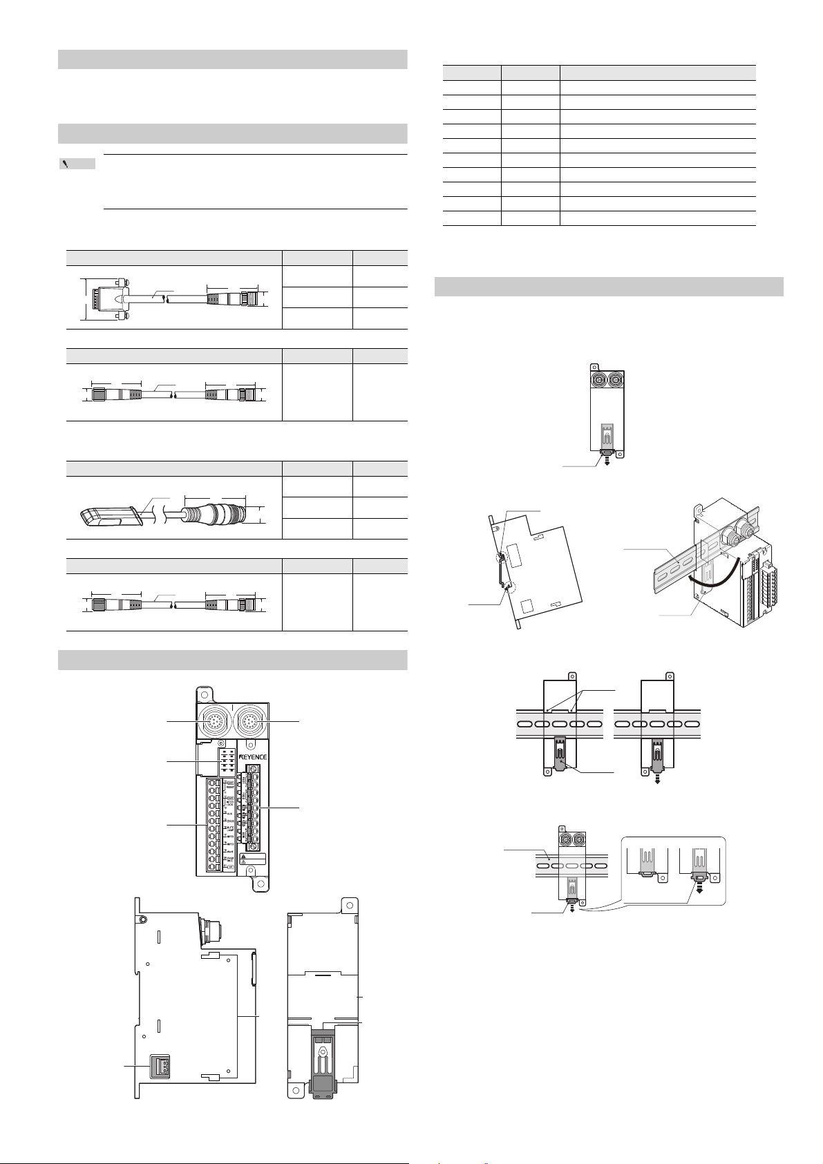
Cable
Be sure to use the following cables for the connection between
the GL-R and the GL-T11R.
The GL-T11R does not operate when combined with other GL-R
cables.
■ GL-R Series
● Unit connection cable
Shape Model Length
φ5.8
31.5
● Extension cable
Shape Model Length
■ GL-S Series
● Unit connection cable
Shape Model Length
● Extension cable
Shape Model Length
45
GL-RPT03PM 0.3 m
GL-RPT3PM 3 m
φ17
GL-RPT5PM 5 m
GL-RCT10PM 10 m
GL-SPT3P 3 m
GL-SPT5P 5 m
GL-SPT10P 10 m
■ Indicators
Name Light color Description
POWER Green Lights when power is supplied
FSD ON Green Lights when FSD turns ON
FSD OFF Red Lights when FSD turns OFF
ERROR Red Lights when an error condition occurs
MUTE 1 Orange Lights when muting input 1 turns ON
MUTE 2 Orange Lights when muting input 2 turns ON
*1, *2
*1
*1
RESET Orange Lights when reset input turns ON
WAIT Orange Lights when wait input turns ON
*1
EDM Orange Lights when EDM input turns ON
O-RIDE Orange Lights when override input turns ON
*1 When GL-R Series functions are switched using the Safety Device Configurator
setting software, indicators light up according to each function’s input status.
*2 For the GL-S Series, this indicator is fixed to being off.
*1
Installation
■ DIN rail Mounting
1 Push hook B down with a screwdriver to release the lock mechanism.
23
Part Names
GL-RCT10PM 10 m
4
Removing from DIN rail
3
GL-T11R-IM-E
Page 4

■ Screw Mounting
Point
Reference
2-φ4.2 (mounting hole)
30mm
30mm
30mm
GL-T11R
*Install while
being careful of
the connectors
DANGER
Receiver Connector (black)
Transmitter Connector (grey)
Receiver cable
(Black connector end)
Transmitter cable
(Gray connector end)
Connector end
The two mounting holes are used to install the
GL-T11R with two M4 screws.
(Recommended tightening torque: 0.7 N•m)
124
37
Always leave at least 30 mm of open space between the GL-T11R
and other equipment or walls.
* When using the SL-U2, position the SL-U2 at least 30 mm from
the edge of the cabinet.
Connection to the SL-U2 Recommended Power Supply
The power can be supplied by connecting to the SL-U2 dedicated power
source via the connector on the side.
Connection to the GL
Cable Specification
(1) Cable length
z GL-R Series
When using the main unit connection cable and the extension cable
together, the total length of the combined cables must be 30 m or
less for the transmitter and receiver respectively.
z GL-S Series
When using the main unit connection cable, the extension cable
and the linking cable, the total length of the combined cables must
be 20 m or less for both the transmitter and receiver.
Cables must be within the lengths specified. Failure to follow
this specification may cause improper operation of the safety
functions and may cause a dangerous situation.
(2) Minimum cable bending radius : 5 mm (10 mm for the part where the
connector to the GL-T11R is attached)
1 Remove the seal on the side of the GL-T11R that protects the connector
port.
2 [For DIN rail mounting]
• Mount the GL-T11R and the SL-U2 to the DIN rail, and slide together
to couple the connectors.
[For screw mounting]
• Couple the connector according to the figure above.
3 Slide the SL-U2 connection hook to secure it to the GL-T11R.
When not using the SL-U2, connect a power source to the power input
terminals found on the relay output terminal block.
"Wiring Example" (page 6)
(3) Identification of connector cables
Types can be distinguished by the color of the connector end.
Cables for Transmitter: Gray connector end
Cables for Receiver : Black connector end
Point
Be sure to connect the unit connection cable for the receiver to
the GL receiver and the unit connection cable for the transmitter
to the GL transmitter.
GL-T11R-IM-E
4
Page 5

Wiring
Point
Reference
Reference
POWER RESET
FSD-ON
WAIT
FSD-OFF
EDM
ERROR
O-RIDE
MUTE1 MUTE2
Electrical hazard
CAUTION
Signal input/output
terminal block
Relay output
terminal block
NOTICE
Push in the orange projection
using the flat-head screwdriver.
Insert the cable.
10 mm
Insert the cable.
Insert the flat-head screwdriver
to the square hole.
10 mm
GL-R main unit
Receiver
No.
Name
1 OSSD2
2 Not used
3 OSSD1
4 Reset input
*1
5
Synchronization 1 (RS485+)
6
Synchronization 2 (RS485-)
7 24V
8 AUX output
*1
9 EDM input
10 0V
11
Interlock selection input
*1
12 FE
*1
Transmitter
No.
Name
1 Wait input
*1
2 Not used
3 Override input
*1
4 Error output
*1
5
Synchronization 1 (RS485+)
6
Synchronization 2 (RS485-)
7 24V
8
Muting lamp output
*1
9 Muting input 2
*1
10 0V
11 Muting input 1
*1
12 FE
*1
Relay unit
Relay output terminal block
No.
Name
1
FSD1
2
3
FSD2
4
5FE
*1
60V
7 24V (input)
8 EDM input (24V)
9 EDM input
Signal input/output terminal block*1
No.
Name
10 Reset input (24V)
11 Reset input
12
Interlock selection input (24V)
13
Interlock selection input
14 AUX output
15 Error output
16 Muting lamp output
17 Muting input 1
18 Muting input 2
19 Wait input
20 Override input
21 0V
6
10
11 12
3
4
5
21
9
8
7
6
10
12 11
9
8
7
12
3
4
5
Under factory default settings, shorting bars are connected between terminals 8 and 9, and terminals 10 and 11.
■ GL-R Series
The GL-R Series operates with the following settings under the factory
default settings.
• Interlock function: Not used (Auto reset mode)
• EDM function: Not used
If a setting change is not necessary, use as it is. For details of each function, refer to the "GL-R User’s Manual".
■ GL-S Series
The GL-S Series operates with the following settings under the factory
default settings.
• EDM function: Not used
Not all of the input/output functions assigned to the signal input/output terminals can be used. Use the signal input/output terminals with the factory
default settings.
■ Wiring method
(1) Wiring the Relay Output Terminal Block
• Connectable cable : AWG24 to 12 (single wire, stranded wire)
• Connectable wire ferrule diameter: 1.3 - 2.6mm
• Cable strip length:
(2) Wiring the Signal Input/Output Terminal Block
■ Input/Output assignment
Signal input/output terminal block
(GL-R Series only)
No.
10 Reset input (24V) 1
11 Reset input 2
12 Interlock selection input (24V) 3
13 Interlock selection input 4
14 AUX output 5 FE
15 Error output 6 0V
16 Muting lamp output 7 24V (input)
17 Muting input 1 8 EDM input (24V)
18 Muting input 2 9 EDM input
19 Wait input
20 Override input
21 0V
For the GL-R Series, the functions are switched to different
functions according to the settings configured with the "Safety
Device Configurator" PC setting software.
When the settings are changed, check the wiring referring to the
internal circuit diagram in the next section.
For the GL-R Series, the power source can be supplied to the muting
device or muting lamp from each 24V terminal. (The total supply
current is 95mA or less. The voltage decreases by approx. 1V from the
voltage input to GL-T11R.)
Relay output terminal block
Name No. Name
FSD1
FSD2
*
* Power supply terminal for GL-T11R.
Do not connect when the SL-U2
power source is connected to the
side of GL-T11R.
• Connectable cable : AWG24 to 12 (single wire, stranded wire)
• Connectable wire ferrule diameter: 1.3 - 2.1mm
• Cable strip length:
Do not perform pre-tinning on the cable end.
Internal circuit diagram
K2
K1
*1 These functions cannot be used with the GL-S.
M14 connector male pin array M14 connector female pin array
K1
K2
5
GL-T11R-IM-E
Page 6

Wiring Example
Point
K3
K3
F1
F2
K4
K3
K4
M
K4
Relay output terminal block
Name No.
FSD1
1
2
FSD2
3
4
FE 5
0V
*1
6
24V (input)
*1
7
EDM input (24V)
*2
8
EDM input
*2
9
PLC IN
P1
L1
S2
S3
P2
S1
Signal input/output terminal block
Name No.
Reset input (24V)
*3
10
Reset input
*3
11
Interlock selection input (24V) 12
Interlock selection input 13
AUX output 14
Error output 15
Muting lamp output 16
Muting input 1 17
Muting input 2 18
Wait input 19
Override input 20
0V 21
Black
Black
Blue
Brown
Brown
Blue
K3
K3
F1
F2
K4
K3
K4
M
K4
Relay output terminal block
Name No.
FSD1
1
2
FSD2
3
4
Not used 5
0V
*1
6
24V (input)
*1
7
EDM input (24V)
*2
8
EDM input
*2
9
Relay output terminal block
Relay board for the GL-T11R
2xφ4.2
(112)
35.9 49.8
3.5
83.8
(100.7) (16)
37
135
124
23
23
11
48
Replacing the Relay Board
■ GL-R Series
This wiring example illustrates the case of the following settings.
• Interlock function: Used (Manual reset mode)
• EDM function: Used
• Muting function: Used
The relay used for the FSD of the GL-T11R can be replaced without rewiring the connection terminal.
1 Prepare the relay board for the GL-T11R (OP-87682).
2 Turn off the power to the GL-T11R and all the devices connected to the
GL-T11R.
3 Loosen the two terminal replacement screws, and remove the relay
output terminal block.
4 Loosen the two relay board replacement screws and remove the cur-
rent relay board from the GL-T11R.
■ GL-S Series
■ Meaning of symbols
F1, F2 : Fuse
K3, K4 : External device (Magnet contactor, etc.)
S1 : Switch for reset (N.O.)
S2 : Switch for wait input (N.O.)
S3 : Switch for override (N.O.)
L1 : Muting lamp (Incandescent lamp or LED lamp)
P1, P2 : Muting device
(Photoelectric sensors with built-in amplifiers such as PZ (PNP
output), etc.)
M : 3-phase motor
PLC : For monitoring use. This is a NON-SAFETY RELATED system.
S2 and PLC are NON-SAFETY RELATED systems.
*1 No. 6 and No. 7 do not need to be wired when the SL-U2 is connected.
*2 If it is not necessary to perform error detection for K3 and K4 (when
EDM input is not used), use the shorting bar between No. 8 and No.
9.
*3 In the auto reset mode, use the shorting bar between No. 10 and No.
11. To release the error condition of a GL-R through the reset input,
connect a N.C. switch.
• For the GL-R Series, the functions are switched to different
functions according to the settings configured with the "Safety
Device Configurator" PC setting software. When the settings
are changed, check the wiring referring to the internal circuit
diagram in the previous section.
• The total electric current supplied from each 24 V terminal of
the GL-T11R must be 95 mA or less.
GL-T11R-IM-E
5 Install the new relay board in the GL-T11R and tighten the relay board
replacement screws. (Recommended tightening torque: 0.3 N•m)
6 Attach the relay output terminal block to the relay board and tighten the
terminal replacement screws. (Recommended tightening torque: 0.3
N•m)
7 Check the operation according to the checklist.
External Dimensions Diagram
6
Page 7

Specifications
OSSD of GL
FSD
10ms 32ms
Specified
period of time
0.3 s*
Error condition
OSSD of GL
FSD
EDM input
10ms 32ms 10ms
Specified
period of time
0.3 s*
Response Time for Combination Between GL and GL-T11R
Model GL-T11R
Supported model GL-R Series/GL-S Series
Relay
output
Response
time
Life-span
Non-safety
output
External
input
Power
source
Environment
resistance
Material Main unit case Polycarbonate
Weight Approx. 310 g
Applicable
standard
FSD1, 2
ON → OFF GL + 10 ms
OFF → ON GL + 32 ms
Electrical lifespan
AUX output*
Error output*
Muting lamp
1
output*
EDM input [GL-R Series]
Wait input*
Reset input*
Muting input 1,
1
2*
Override input*
Power source
voltage
Consumption
current
Enclosure rating
Pollution degree 2
Overvoltage
category
Ambient
temperature
Storage
ambient
temperature
Ambient
humidity
Storage
ambient
humidity
Elevation 2000 m or less
Vibration
Shock
EMS EN61496-1, UL61496-1, IEC61496-1
EMC
EMI
Safety
250 V AC, 6 A 30 V DC, 6 A (Resistance load)
240 V AC, 2 A (COSφ=0.3) (Inductive load)
24 V DC, 1 A (COSφ=0.3) (Inductive load)
100,000 cycles or more with 250 V AC, 6 A
(Open/Close frequency 20 times/min.)
100,000 cycles or more with 30 V DC, 6 A
(Open/Close frequency 20 times/min.)
500,000 cycles or more with 250 V AC, 1 A
(Open/Close frequency 30 times/min.)
500,000 cycles or more with 30 V DC, 1 A
(Open/Close frequency 30 times/min.)
AC15: 100,000 cycles or more with 240 V AC, 2 A
(Open/Close frequency 20 times/min., cosφ=0.3)
DC13: 100,000 cycles or more with 24 V DC, 1 A
(Open/Close frequency 20 times/min., L/R=48ms)
1
1
1
1
(Connectable to PNP/NPN input device)*
50mA or less, Residual voltage 2.5 V or less
Incandescent lamp (24 V DC, 1 to 5.5 W)
Connectable to LED lamp (Load current 10 to 230 mA)
ON voltage: [Power source voltage - 5 V] to
[Power source voltage]
OFF voltage: Open or 0 to 3 V
Short-circuit current: Approx. 2.5 mA
(EDM input only approx. 10 mA)
[GL-S Series]
1
Short-circuit current (EDM input): Approx. 1 mA
24 V DC ± 10%, Ripple (P-P) 10% or less, Class2
100mA or less (at 24 V DC, GL-T11R alone)
IP20 (IEC60529) Install inside a control panel of
10 to 55 Hz 0.7 mm compound amplitude,
20 sweeps each in X, Y, and Z directions
100 m/s
1,000 times each in X, Y, and Z directions
EN55011 ClassA, FCC Part15B ClassA,
EN61496-1, UL61496-1, IEC61496-1 (Type 4 ESPE)
Resistance load
Resistance load
Resistance load
Resistance load
Inductive load
Inductive load
Transistor output
(When the cable length
between GL-R and GL-T11R is 5 m)
IP54 or greater
-10 to +55 °C (No freezing)
-25 to 60 °C (No freezing)
15 to 85% RH (No condensation)
15 to 95% RH
2
(Approx. 10 G) 16 ms pulse,
ICES-003 ClassA
EN ISO13849-1: 2008 (Cat4 PL e)
UL508, EN50178
2
* For operations of each function and detailed specifications, refer to the
"GL-R User’s Manual" or "GL-S User’s Manual".
*1 When connected to the GL-S Series, these functions cannot be used.
*2 The output operation is the same as that when the PNP output type
cable is used.
The following are the response times for the combination between GL and
GL-T11R.
A) Maximum response time when the FSD goes to the OFF state after the
GL detects an interruption in the detection zone.
The response time* (ON to OFF) of the GL connected to GL-T11R +
10 ms
B) Maximum response time when the FSD goes back to the ON state after
the GL detects no interruption in the detection zone.
The response time* (OFF to ON) of the GL connected to GL-T11R +
32 ms
* For details on the response time, refer to the GL-R user's manual
or the GL-S user's manual.
The following are examples of total response times in cases where the
GL-T11R is connected to the GL with the series-connection cable.
When connecting the GL-R32H (32 beam axes), GL-R24H (24 beam
axes), and GL-R12L
unit is 7.9 ms, 7.0 ms, and 6.6 ms respectively
(12 beam axes) in series, the response time of each
. The response time (ON to
OFF) is 7.9 + 7.0 + 6.6 - 4.2* + 10 = 27.3 ms and the response time (OFF
to ON) is 50.6 + 49.3 + 48.7 - 84* + 32 = 96.6 ms
* When calculating the response time of the GL-R using two con-
nected sub units, sum the response time of all three GL-R and
then subtract 4.2 ms (ON to OFF) or 84 ms (OFF to ON). For more
detail, refer to the GL-R user’s manual.
■ Time Chart
FSD
ON
OFF
ON
OFF
When EDM input is used
ON
OFF
ON
OFF
ON
OFF
(1) The normal operation continues because FSD operates within the per-
missible time (0.3 sec.) according to the OSSD operation of GL.
(2) The GL enters an error condition as "EDM error" because FSD does not
operates within the permissible time (0.3 sec.).
* For the GL-R Series, the time can be changed using the Safety Device
Configurator.
7
GL-T11R-IM-E
Page 8

Checklist
2013
12530E 1053-1 96M12530
When the installation and wiring of the GL and the GL-T11R are completed,
the responsible personnel must verify operations in accordance with the
checklist shown below. The following checklist covers the minimum requirements for the GL-T11R. The check items required may vary depending on the
machine where the GL-T11R is installed, and the laws, rules, regulations and
standards in the country or region in which the GL-T11R will be used. KEYENCE strongly recommends that other necessary check items should be
added by the responsible personnel for the use of the GL-T11R.
This checklist only lists the items related to the GL-T11R, so refer to the GL-R
instruction manual or the GL-S instruction manual to create a checklist that
also covers the GL.
■ Inspection after installation
When the installation of the GL-T11R is completed, the responsible personnel
must verify the operation of the GL-T11R in accordance with the checklist
shown below.
The checklist below covers the minimum requirements for the GL-T11R. The
check items required may vary depending on the machine on which the GLT11R is installed and the laws, rules, regulations and standards in the country
or region in which the GL-T11R will be used. KEYENCE strongly recommends
that other necessary check items should be added by the responsible personnel for the use of the GL-T11R.
(1) Pre-check for installation condition
❑
The machine on which the GL-T11R is installed can stop when it
receives the FSD output from the GL-T11R.
❑
The interlock reset mechanisms (such as switches) are installed so that
the whole hazardous zone can be checked by the responsible personnel and that operations of the interlock reset mechanisms are not possible within the hazardous zone.
❑
The GL-T11R is installed in an enclosure of IP54 or greater.
❑
The DIN rail is fixed on the control panel (enclosure) with adequate
strength to support the weight of the GL-T11R.
❑
Space is ensured around the GL-T11R for ventilation or heat release as
specified in this manual.
❑
The installation of the GL-T11R fulfills conditions specified in this
instruction manual and the requirements of the laws, rules, regulations
and standards in the country or region where the GL-T11R is used.
(2) Pre-check for wiring
❑
To supply power to the GL-T11R, the SL-U2 power supply recommended by KEYENCE is used, or a different 24 VDC power supply that
satisfies the power supply conditions specified in this instruction manual is used.
❑
The cable for transmitter (Gray M14 connector end) is connected to the
cable connector for transmitter, and the cable for receiver (Black M14
connector end) is connected to the cable connector for receiver.
❑
The safety related machine control system is established by using both
of the safety outputs provided on the GL-T11R.
❑
The polarity is correct for connection to the power supply.
❑
The wait input is not connected to the output from the safety components comprising a part of the safety related machine control system.
❑
Non-safety related outputs are not used as a part of the safety related
control system.
❑
Wiring is performed in a manner that complies with the requirements of
Clause 9.4.3 in IEC60204-1:2005 in order for the protection against
malopeation due to earth fault.
■ Regular (periodical) inspection
The responsible personnel must perform a regular inspection.
It is recommended to perform a regular inspection at least once every six
months.
Note that the following inspection items comprise only a bare minimum
inspection. KEYENCE Corporation strongly recommends including the necessary checking items into this checklist based on the judgment of the responsible personnel since additional criteria may be necessary depending on both
the machine to which the GL-T11R is installed and the laws, rules, regulations
and standards in the country or region in which the GL-T11R is used/installed.
The result of this inspection must be kept on record along with the machine
log.
❑
Conductive contamination does not occur due to oil or dust adherence.
❑
The response time of the whole machine control system is below the
design value and normal.
❑
Devices with a finite lifetime such as switches, relays or contactors are
still functional.
❑
Wiring is correctly performed and no modifications or connection
changes are made that may adversely affect the safety related system
of the equipment.
❑
There are no disconnected or loose wires on the connection terminal.
❑
The open/close cycle of the FSD is within the lifespan. If needed,
replace it by referring to "Replacing the Relay Board".
GL-T11R-IM-E
■ Inspection as needed
In the following cases, perform inspection for all items.
• When the unit is installed for the first time
• When the parts and wires relating to this system are replaced or changed
• When an abnormal operation is found
WARRANTIES AND DISCLAIMERS
(1) KEYENCE warrants the Products to be free of defects in materials and
workmanship for a period of one (1) year from the date of shipment. If any
models or samples were shown to Buyer, such models or samples were used
merely to illustrate the general type and quality of the Products and not to
represent that the Products would necessarily conform to said models or
samples. Any Products found to be defective must be shipped to KEYENCE
with all shipping costs paid by Buyer or offered to KEYENCE for inspection
and examination. Upon examination by KEYENCE, KEYENCE, at its sole
option, will refund the purchase price of, or repair or replace at no charge any
Products found to be defective. This warranty does not apply to any defects
resulting from any action of Buyer, including but not limited to improper
installation, improper interfacing, improper repair, unauthorized modification,
misapplication and mishandling, such as exposure to excessive current, heat,
coldness, moisture, vibration or outdoors air. Components which wear are not
warranted.
(2) KEYENCE is pleased to offer suggestions on the use of its various Products.
They are only suggestions, and it is Buyer's responsibility to ascertain the
fitness of the Products for Buyer’s intended use. KEYENCE will not be
responsible for any damages that may result from the use of the Products.
(3) The Products and any samples ("Products/Samples") supplied to Buyer are not
to be used internally in humans, for human transpor tation, as safety devices or
fail-safe systems, unless their written specifications state otherwise. Should any
Products/Samples be used in such a manner or misused in any way, KEYENCE
assumes no responsibility, and additionally Buyer will indemnify KEYENCE and
hold KEYENCE harmless from any liability or damage whatsoever arising out of
any misuse of the Products/Samples.
(4) OTHER THAN AS STATED HEREIN, THE PRODUCTS/SAMPLES ARE
PROVIDED WITH NO OTHER WARRANTIES WHATSOEVER. ALL
EXPRESS, IMPLIED, AND STATUTORY WARRANTIES, INCLUDING,
WITHOUT LIMITATION, THE WARRANTIES OF MERCHANTABILITY,
FITNESS FOR A PARTICULAR PURPOSE, AND NON-INFRINGEMENT OF
PROPRIETARY RIGHTS, ARE EXPRESSLY DISCLAIMED.
IN NO EVENT SHALL KEYENCE AND ITS AFFILIATED ENTITIES BE
LIABLE TO ANY PERSON OR ENTITY FOR ANY DIRECT, INDIRECT,
INCIDENTAL, PUNITIVE, SPECIAL OR CONSEQUENTIAL DAMAGES
(INCLUDING, WITHOUT LIMITATION, ANY DAMAGES RESULTING FROM
LOSS OF USE, BUSINESS INTERRUPTION, LOSS OF INFORMATION,
LOSS OR INACCURACY OF DATA, LOSS OF PROFITS, LOSS OF
SAVINGS, THE COST OF PROCUREMENT OF SUBSTITUTED GOODS,
SERVICES OR TECHNOLOGIES, OR FOR ANY MATTER ARISING OUT
OF OR IN CONNECTION WITH THE USE OR INABILITY TO USE THE
PRODUCTS, EVEN IF KEYENCE OR ONE OF ITS AFFILIATED ENTITIES
WAS ADVISED OF A POSSIBLE THIRD PARTY’S CLAIM FOR DAMAGES
OR ANY OTHER CLAIM AGAINST BUYER. In some jurisdictions, some of
the foregoing warranty disclaimers or damage limitations may not apply.
BUYER'S TRANSFER OBLIGATIONS:
If the Products/Samples purchased by Buyer are to be resold or delivered to a
third party, Buyer must provide such third party with a copy of this document,
all specifications, manuals, catalogs, leaflets and written information provided
to Buyer pertaining to the Products/Samples.
E 1101-3
Document Control No. 981BE151-01
8
 Loading...