

Page 1
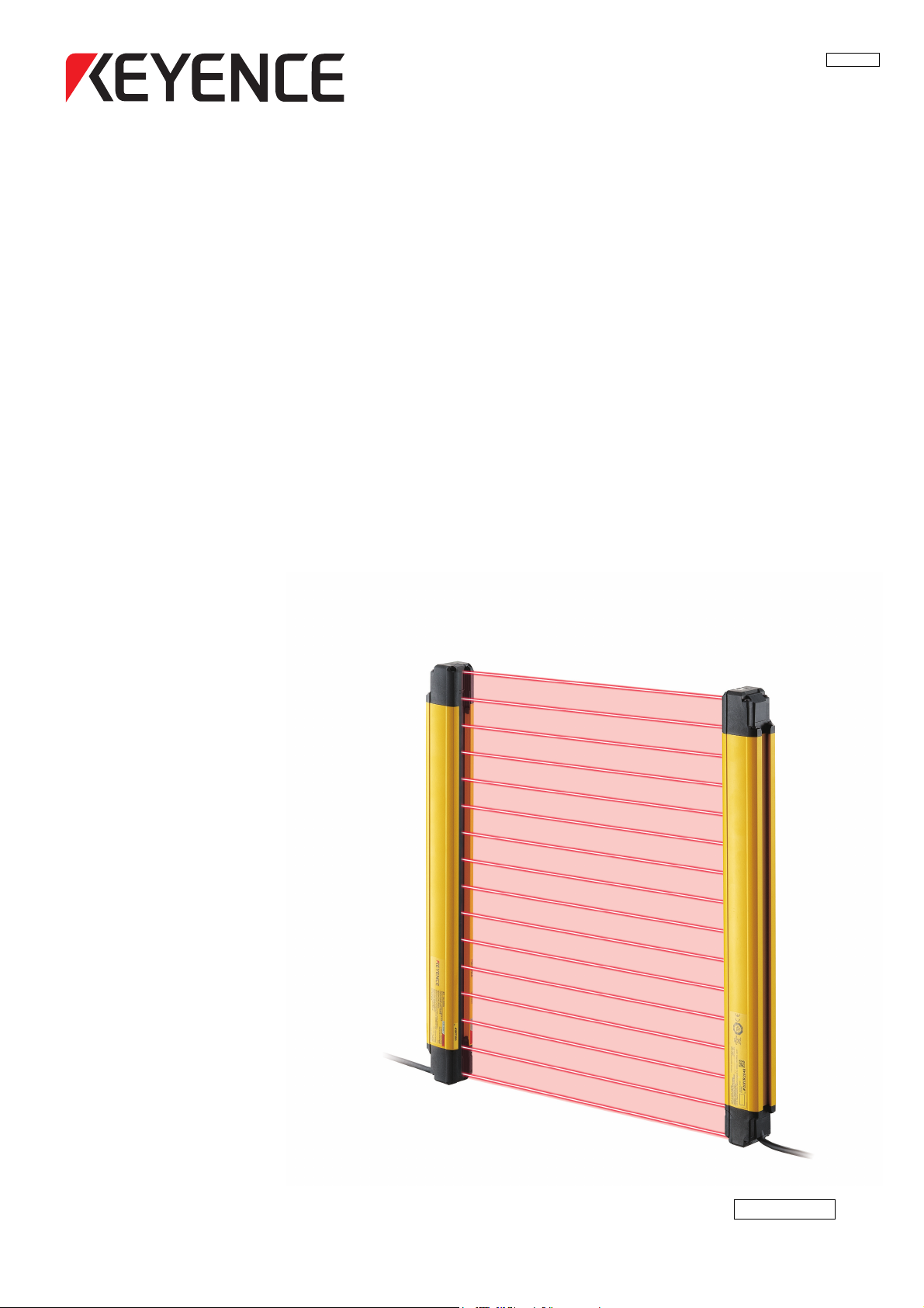
Safety Light Curtain for Press Machines
GL-RHG Series
User's Manual
237GB
No.981BE124-01
Page 2
Introduction
This user's manual describes handling, operation, and precautionary information for the GL-RHG Series
Safety Light Curtain for Press Machines ("GL-RHG").
Read this user's manual thoroughly before operating the GL-RHG in order to understand the device features, and keep this user's manual readily available for reference. Ensure that the end user of this product
receives this manual.
Symbols
The following symbols alert you to important messages. Be sure to read these messages carefully.
DANGER
NOTICE
Point
Reference
It indicates a hazardous situation which, if not avoided, will result in death or serious injury.
It indicates a situation which, if not avoided, could result in product damage as well as
property damage.
It indicates additional information on proper operation.
It indicates tips for better understanding or useful information.
Indicates reference pages in this or another manual.
Page 3
Safety Information for GL-RHG Series
General precautions
• You must verify that the GL-RHG is operating correctly in terms of functionality and
performance before the start of machine and the operation of the GL-RHG.
• KEYENCE does not guarantee the function or performance of the GL-RHG if it is used in a
manner that differs from the GL-RHG specifications contained in this user's manual or if
the GL-RHG is modified by the customer.
• When using the GL-RHG to protect machine operators against a hazard or hazardous
zone or using the GL-RHG as a safety component for any purpose, always follow the
applicable requirements of the laws, rules, regulations and standards in the country or
region where the GL-RHG is used. For such regulations, you should directly contact the
regulatory agency responsible for occupational safety and health in your country or
region.
• Depending on the type of machine on which the GL-RHG is to be installed, there may be
special safety regulations related to the use, installation, maintenance, and operation of
the safety component. In such a case, you must fulfill such safety regulations. The
responsible personnel must install the GL-RHG in strict compliance with such safety
regulations.
• The responsible personnel must do the training to the assigned personnel for the correct
DANGER
use, installation, maintenance, and operation of the GL-RHG. "Machine operators" refers
to personnel who have received appropriate training from the responsible personnel and
are qualified to operate the machine correctly.
• Machine operators must have specialized training for the GL-RHG, and they must
understand and fulfill the safety regulations in the country or region in which they are
using the GL-RHG.
• When the GL-RHG fails to operate, machine operators must immediately stop the use of
the machine and the GL-RHG and report this fact to the responsible personnel.
• The GL-RHG is designed with the assumption that it would be correctly installed in
accordance with the installation procedures described in this user's manual and correctly
operated according to the instructions in this user's manual. You must perform an
appropriate installation of the GL-RHG after performing a sufficient risk assessment for
the target machine.
• Be sure to absolutely confirm that there is nobody in the hazardous zone, before you
remove the GL-RHG from the machine for replacement or disposal.
• When disposing the GL-RHG, always follow the applicable requirements of the laws,
rules, regulations and standards in the country or region where the GL-RHG is used.
• The GL-RHG should be processed as an industrial waste product when being disposed.
GL-RHG-M-NO0-E
237GB
1
Page 4
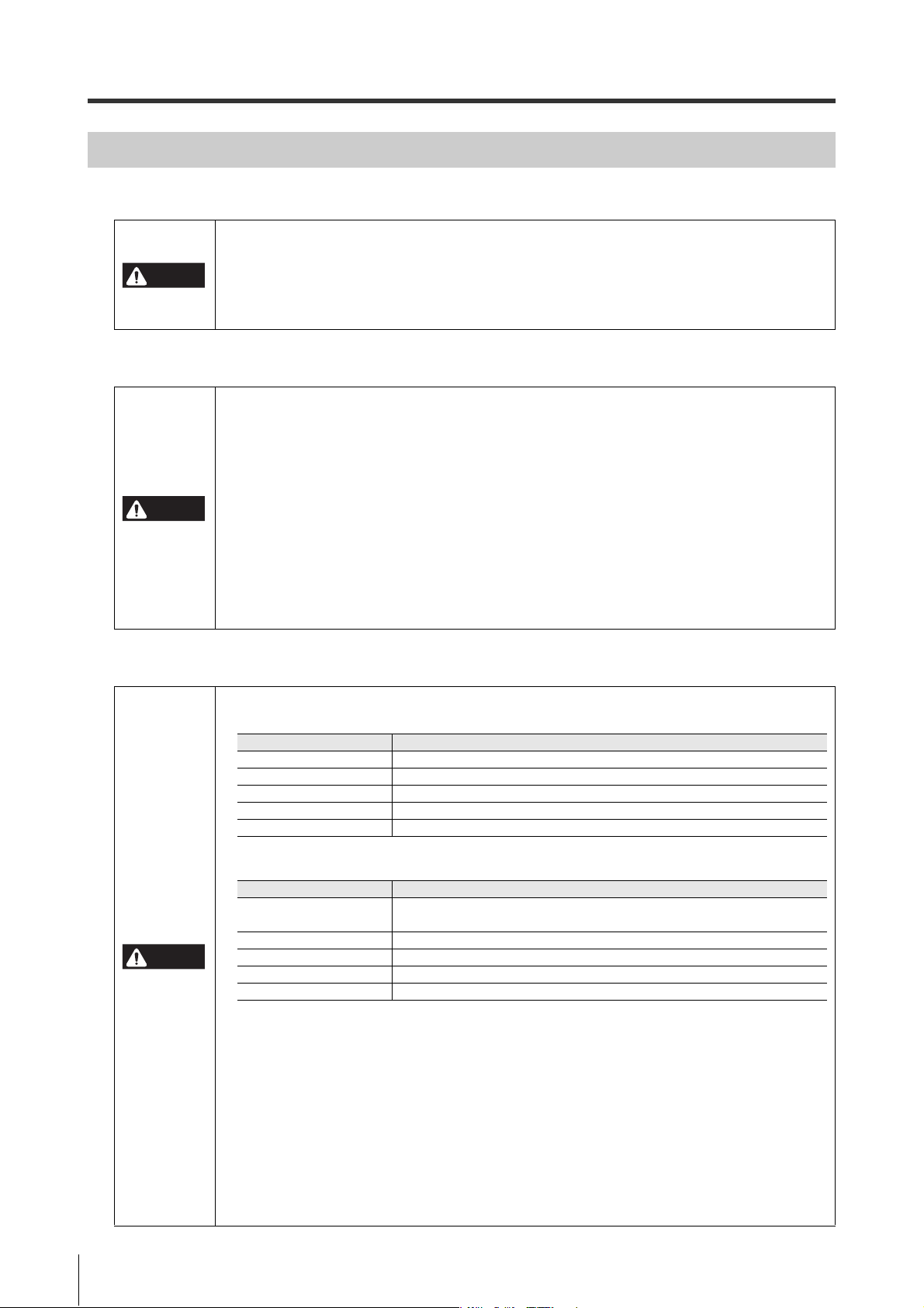
Precaution on use
Item Specifications
Ty pe
Press machine equipped with a quick-stopping device and restart prevention mechanism
Pressure capability 50,000 kN or less
Emergency stop time 500 ms or less
Length of strokes Less than (protection height – Die height)
Size range of metal die Less than the bolster width
Item Specifications
Ty pe
Shearing machine (paper cutting machine) equipped with a quick-stopping
mechanism and restart prevention mechanism
Cut thickness 200 mm or less
Cut width 5,000 mm or less
Blade length 5,500 mm or less
Emergency stop time 500 ms or less
Operators
• In order to operate the GL-RHG correctly, the responsible personnel and machine
operators must fulfill all of the procedures described in this user's manual.
DANGER
Environment of use
DANGER
• No person other than the responsible personnel and machine operators should be
allowed to install or test the GL-RHG.
• When performing electrical wiring, always fulfill the electrical standards and regulations
for the country or region in which the GL-RHG is used.
• Do not use the GL-RHG in an environment (temperature, humidity, interfering light, etc.)
that does not conform to the specifications contained in this user's manual.
• Be sure to confirm that the GL-RHG keeps normal operation when electromagnetic
radiation is generated by wireless devices. (If you use wireless devices such as cellular
phones or transceivers in the vicinity of the GL-RHG.)
• The GL-RHG is not designed to be explosion-proof. Never use it in the presence of
flammable or explosive gases or elements.
•
Be sure to confirm no deterioration in product quality if you use the GL-RHG in the presence
of substances, such as heavy smoke, particulate matter, or corrosive chemical agents.
• Do not install the GL-RHG in areas where the GL-RHG is exposed to intense interference
light such as direct sunlight, and direct or indirect light from an inverter-type fluorescent
lamp (rapid-start type lamp, high-frequency operation type lamp, etc).
• Be sure to absolutely confirm that there is nobody in the hazardous zone before the
override function is activated. Failure to follow this warning results in significant harm to
the machine operators, including serious injury or death.
Targ et m ach ine
• When using GL-RHG as a press machine safety device in Japan, press machines other
than those fulfilling the following specifications cannot be used.
•
When using GL-RHG as a shearing machine (paper cutting machine) safety device in Japan, shearing
machines (paper cutting machines) other than those fulfilling the following specifications cannot be used.
DANGER
• The machine on which the GL-RHG is to be installed must be susceptible to an
emergency stop at all operating points during its operation cycle. Do not use the GL-RHG
for machines with irregular stop times.
• Do not use the GL-RHG for power presses equipped with full-revolution clutches.
• The GL-RHG cannot be used as a PSDI because it does not fulfill the requirements of
OSHA 1910.217(h). Refer to OSHA 1910.217 for the PSDI mode.
• Do not use the GL-RHG to control (stop forward motion, etc.) trains, cars and other
transportation vehicles, aircraft, equipment for use in space, medical devices, or nuclear
power generation systems.
• The GL-RHG is designed to protect people or objects from going into/approaching
protective zone against machine's hazard or hazardous zone. It cannot provide protection
2
against objects or materials that are expelled from the machine's hazard or hazardous
zone, so you must establish additional safety measures such as installing safeguards
when there is the possibility of such projectiles.
GL-RHG-M-NO0-E
Page 5
Installation
DANGER
• The GL-RHG must be installed only after ensuring the minimum safety distance between
the GL-RHG and the hazardous zone or hazard as established by the applicable
regulations in the country or region in which the GL-RHG is used. (e.g. EN ISO13855 (ISO
13855) in EU countries)
• Choose locations for the installation of the GL-RHG transmitters and receivers so that
they are not subject to the effects of light reflected from glossy surfaces in the area.
• The GL-RHG must be installed so that the machine operator is able to go into or approach
the hazardous zone or hazards only by passing through the detection zone of the
GL-RHG. Strictly avoid installation that allows the machine operator or a part of the
machine operator's body to go into or approach the hazardous zone or hazards without
passing through the protective zone of the GL-RHG or to remain in position between the
protective zone of the GL-RHG and the hazardous zone or hazard.
• You must always perform the pre-check tests after installing the GL-RHG in accordance
with the pre-check test procedures, such as items specified in this user's manual, in order
to verify that the test pieces can be detected in all of the protective zones.
• Muting is a function to allow a temporary automatic suspension of the GL-RHG safety
functions while the GL-RHG is receiving a signal from muting devices (such as sensors or
switches). Therefore, additional safety measures are required for the machine on which
the GL-RHG is installed in order to ensure safety while the muting is activated.
• Muting devices, the installation of those devices and the procedure to activate the muting
function must fulfill the conditions specified in this user's manual and the requirements
of the laws, rules, regulations and standards in the country or region in which the
GL-RHG and those devices are used. Failure to follow this warning may result in
significant harm to the machine operators, including serious injury or death.
• When you install muting devices (such as sensors or switches) for muting, the following
conditions must be fulfilled.
(1) Muting devices must be installed so that the muting cannot be activated if the
hazardous zone of the machine is in an unsafe condition or cycle.
(2) Muting devices must be installed so that the muting cannot be activated even if
the personnel is accidentally approaching the detection zone of the GL-RHG.
• The muting device must be installed such that only responsible personnel have access to
that device to change the installation or orientation. Special tools must be required to
ensure that only responsible personnel are capable of installation, orientation or change
of muting device.
• Only the responsible personnel may be allowed to install or wire the devices to activate
the muting function.
• The installation of a muting lamp may be required by the laws, rules, regulations, and
standards in the country or region in which the GL-RHG is used if you apply the muting
function. It depends on the machine application and/or the result of your risk assessment.
If it is necessary for you to provide a muting lamp, you must fulfill the requirements
because you are fully responsible for installation of the muting lamp.
• The installation of the indication for override may be required by the laws, rules,
regulations, and standards in the country or region in which the GL-RHG is used if you
ap
ply the ov
your risk assessment. If it is necessary for you to provide the indication for override, you
must fulfill the requirements because you are fully responsible for installation of the
indication for override.
• The customer is fully responsible for complying with the requirements for muting and/or
override. Those who use muting and/or override must fulfill all of the requirements related
to muting and/or override. KEYENCE accepts NO responsibility and NO liability for any
damage or any injury due to the unauthorized installation, usage or maintenance, which
are not specified in this user's manual, and/or due to noncompliance with the laws, rules,
regulations and standards in the country or region in which the GL-RHG is used.
erride function. It depends on the machine application and/or the result of
GL-RHG-M-NO0-E
3
Page 6
DANGER
• When the reduced resolution function is applied, the detection capability varies
according to your configuration. Make sure to accurately calculate the safety distance
according to the detection capability, and install the GL-RHG at a distance greater than or
equal to the minimum safety distance away from the hazardous zone or hazard. The
installation of additional safety measures, such as safeguarding, may be required if the
detection capability varies due to the configuration of reduced resolution. On your own
responsibility, you must perform the risk assessment based on your configuration of
reduced resolution in order to reduce the risk.
• When the fixed blanking function is applied, a hazardous clearance that is not protected
by the GL-RHG may be generated between the obstacle and the GL-RHG. You must install
an additional safety measure such as a safeguard for this clearance.
• The override is a function to allow a temporary manual suspension of the safety functions
of the GL-RHG. Therefore, additional safety measures are required for the whole machine
system on which the GL-RHG is installed in order to ensure safety while the override is
activated.
• Securely tighten mounting brackets and cable connectors used for the installation of the
GL-RHG in accordance with the torque values specified in this user's manual.
• When optical synchronization system is applied and Channel A or B is configured, the
response time is longer than the other case. Make sure to accurately calculate the safety
distance according to the response time, and install the GL-RHG at a distance greater
than or equal to the minimum safety distance away from the hazardous zone or hazard.
Circuit design and wiring
DANGER
• Always turn off the power to the GL-RHG when performing electrical wiring.
• You must fulfill the electrical standards and regulations in the country or region in which
the GL-RHG is being used when you perform the electrical wiring.
• To avoid the risk of electric shock, do not connect any of the GL-RHG inputs to DC power
sources outside of the range of 24 V DC + 20% or to any AC power source.
• To avoid the risk of electric shock, be sure that any hazardous voltage is isolated from all
wiring of the GL-RHG with reinforced insulation or double insulation.
• In order to fulfill the requirements in IEC61496-1, UL61496-1, EN61496-1 and UL508, the
power supply for the GL-RHG must fulfill the conditions listed below.
(a) A rated output voltage of 24 V DC (SELV, Overvoltage Category ) within ±20%.
(b) Double insulation or reinforced insulation between the primary and secondary
circuits.
(c) Output holding time of 20 ms or more.
(d) A power supply must fulfill the requirements of the electrical safety and
electromagnetic compatibility (EMC) regulations or standards in all countries
and/or regions where the GL-RHG is used.
(e) A secondary circuit of power supply (output) must fulfill the requirements for
Class 2 Circuits or Limited Voltage/Current Circuits specified in UL508, if the GL-
R is used in the United States or Canada.
• Do not install the electric wiring of the GL-RHG together with or in parallel with any highvoltage electrical or power lines.
• Both OSSD outputs provided on the GL-RHG must be used to establish a safety-related
machine control system. Establishing a safety-related machine control system with just one
of the OSSD outputs cannot stop the machine due to an OSSD output malfunction and may
result in significant harm to the machine operators, including serious injury or death.
• When using PNP output type cables, do not cause a short-circuit between the OSSD and
+24 V. Otherwise, the OSSDs keep staying at the ON-state and it causes a dangerous
situation.
4
GL-RHG-M-NO0-E
Page 7
DANGER
• When using PNP output type cables, be sure to connect the load between the OSSD and 0 V
to avoid a dangerous situation. If the load is incorrectly connected between the OSSD and
+24 V, the logic of the OSSD operation will be reversed and the OSSD will change to an ON
state when the GL-RHG detects an interruption in the protective zone. This is a dangerous
situation.
• When using NPN output type cables, do not cause a short-circuit between the OSSD and 0 V.
Otherwise, the OSSDs keep staying at the ON-state and it causes a dangerous situation.
• When using an NPN output type cable, be sure to connect the load between the OSSD and
+24 V to avoid a dangerous situation. If the load is incorrectly connected between the
OSSD and 0 V, the logic of the OSSD operation will be reversed and the OSSD will change
to an ON state when the GL-RHG detects the interruption in the protective zone. This is a
dangerous situation.
• Regardless of whether the cables are PNP or NPN type, you must fulfill the requirements
of Clause 9.4.3 in IEC60204-1: 2005 for protection against maloperation due to earth fault.
• All outputs, other than OSSDs, are not allowed to be used as safety outputs for a safetyrelated machine control systems. Usage of these functions as safety outputs may result
in significant harm to the machine operators, including serious injury or death.
• The wait input is not allowed to be connected to the output from any components
comprising a part of the safety-related machine control system. If the wait input is
connected to the output of a safety component it may result in significant harm to the
machine operators, including serious injury or death.
• The transmitter and receiver cables must be within the lengths specified in this user's
manual. Usage of cables longer than the specified length may cause the improper
operation of safety functions and may cause a dangerous situation.
Testing and maintenance
• You must always perform the pre-check test in accordance with the checklist, after
maintenance, adjustment or alignment of the target machine or the GL-RHG and before
the machine startup.
• If the GL-RHG does not operate properly when you perform a pre-check test in
accordance with the checklist specified in this user's manual, do not operate the
DANGER
machine.
• You must periodically examine the machine to verify that all brakes, other stop
mechanisms, and control devices operate reliably and correctly in addition to checking
the GL-RHG.
• The responsible personnel must perform maintenance procedures as specified in this
user's manual to ensure safety to the machine and GL-RHG.
GL-RHG-M-NO0-E
5
Page 8

Precautions on Regulations and Standards
CE Marking
Keyence Corporation has confirmed that this product complies with the essential requirements of the
applicable EC Directive, based on the following specifications.
Be sure to consider the following specifications when using this product in a member state of the European Union.
Machinery Directive (2006/42/EC)
The GL-RHG is a safety component as established by the European Union's Machinery Directive
(2006/42/EC) Annex V. The GL-RHG complies with the following EN Standards and has been certified
by TÜV SÜD Product Service GmbH.
• EN61496-1 Type 4 ESPE
• EN61496-2 Type 4 AOPD
• EN50178
• EN61508, Part 1 to 4 SIL3
• EN62061 SIL CL3
• EN ISO13849-1 Category 4, PL e
EMC Directive (2004/108/EC)
The GL-RHG complies with the following EN Standards
• EN55011 Class A
• EN61496-1 Type 4 ESPE
These specifications do not give any guarantee that the end-product with this product incorporated
complies with the essential requirements of the EMC Directive. The manufacturer of the end-product is
solely responsible for the compliance of the end-product itself according to the EMC Directive.
UL Certificate and North American Regulations
The GL-RHG complies with the following North American and international standards and has received
UL certification and C-UL certification. (CCN: NIPF/NIPF7, File No: E184802)
• UL61496-1 Type 4 ESPE
• UL61496-2 Type 4 AOPD
• UL508
• UL1998
The GL-RHG also complies with the following North American regulations.
• FCC Part 15B Class A Digital Device
• ICES-003 Class A Digital Apparatus
Type examination based on the Chinese standard GB 4584 "压力机用光电保护装置
技术条件"
GL-RHG has passed the type examination based on the Chinese standard GB 4584 "压力机用光电保护装
置技术条件".
• Quality test certificate certificate number: No.20120929
However, if the response time (ON OFF) exceeds 20ms, this product cannot be used as a certified
product. The following two conditions may cause the response time to exceed 20 ms.
• Using GL-RHG in the optical synchronization system and selecting channel A or B
• Make series connection of GL-RHG
"Wiring System" (page 2-2)
"Series connection" (page 2-3)
"Response time (OSSD)" (page 7-5)
6
GL-RHG-M-NO0-E
Page 9

Type examination for "press machine and shearing machine safety device"
GL-RHG has passed the "Type examination" based on the Industrial Safety and Health Law, Article 44-2.
• Type approval certificate number: TA548 (Press machine)
TA552 [Shearing machine (Paper cutting machine)]
Other standards
The GL-RHG has been designed in consideration of the following standards and regulations. For details
regarding the following standards, contact the third-party certification organization, such as UL or TÜV.
• EN60204-1
• EN692
• EN693
• OSHA 29 CFR 1910.212
• OSHA 29 CFR 1910.217
• ANSI B11.1 - B.11.19
• ANSI/RIA R15.06 - 1999
• SEMI S2
• "Guidelines for Comprehensive Safety Standards of Machinery", July 31, 2007, number 0731001
issued by Ministry of Health, Labor, and Welfare in Japan.
GL-RHG-M-NO0-E
7
Page 10

Software License Agreement
The use of [Safety Device Configurator, GL-R configurator, SL-V Configurator] (hereinafter referred to as
[this software]) is subject to the terms outlined in this software license agreement (hereinafter referred to
as [this agreement]) and to the customers consent to this agreement. The customer's use or duplication of
this software, in whole or in part, constitutes the customer's consent to enter into this agreement.
Article 1 (Usage Rights)
1 Contingent of the customer's compliance with the terms of this agreement, KEYENCE Corporation
(hereinafter referred to as KEYENCE) extends to the customer non-exclusive usage rights.
2 The customer may install this software without the limit of the number of the licenses, provided that
this software is used only in the same corporation in order to use our product you have purchased.
Article 2 (Limitations on Duplication)
The customer may make no more than 1 copy of this software for backup purposes only.
Article 3 (Prohibitions)
The customer is prohibited from doing the following with this software.
a. Additions or changes to any or all of the functions of this software. However, installation of updates
or new features provided by KEYENCE is expressly allowed.
b. Reverse compiling or reverse assembling of this software for the purposes of reverse engineering.
c. Sale, transfer, redistribution, license, rental or lease to the third party. This does not include
instances where permission has been obtained from KEYENCE in advance.
Article 4 (Copyright)
The copyrights of this software and all associated documentation are the property of KEYENCE.
Article 5 (Exemption of Liability)
KEYENCE shall not be held liable by the user or third party for any damages arising from the use of
the software.
Article 6 (Support)
Based on this agreement, KEYENCE agrees to provide the customer with technical support in
response to customer questions regarding this software. However, KEYENCE makes no guarantee
that the technical support offered will meet the customer's needs.
Article 7 (Termination of Agreement)
1 Should the customer destroy this software and any backup copies, this agreement will automatically
expire with the customer's cessation of use of this software.
2 KEYENCE reserves the right to unilaterally terminate this agreement should the customer violate
any of the terms of this agreement. In this instance, this software and all copies should be immedi-
ately returned to KEYENCE for destruction.
3 Should KEYENCE be caused damages by the customer's violation of this agreement, the customer
will compensate KEYENCE for those damages.
Article 8 (Basis in Law)
This agreement is to be adjudicated according to Japanese law.
8
GL-RHG-M-NO0-E
Page 11

Table of Contents
Introduction
Symbols
Safety Information for GL-RHG Series ............................................................................... 1
General precautions ....................................................................................................................... 1
Precaution on use ........................................................................................................................... 2
Testing and maintenance ............................................................................................................... 5
Precautions on Regulations and Standards ................................................................................... 6
Software License Agreement .............................................................................................. 8
Table of Contents ................................................................................................................. 9
Chapter 1 Before Use
1-1 Products ................................................................................................................... 1-2
Light curtain unit .......................................................................................................................... 1-2
Cables ......................................................................................................................................... 1-2
Cable protection pipe ................................................................................................................... 1-4
Mounting brackets ....................................................................................................................... 1-5
Antivibration bracket .................................................................................................................... 1-6
Software and Interface Unit ......................................................................................................... 1-7
Dedicated Safety Reley for the GL-R Series (Model: GL-T11R) ................................................. 1-7
1-2 Part Description ....................................................................................................... 1-8
Chapter 2 Functions and Features
2-1 Wiring System ......................................................................................................... 2-2
Wiring system .............................................................................................................................. 2-2
Series connection ........................................................................................................................ 2-3
2-2 Functions ................................................................................................................. 2-4
2-3 OSSD ........................................................................................................................2-5
2-4 External Device Monitoring (EDM Function) ........................................................ 2-6
Wiring .......................................................................................................................................... 2-6
Time chart .................................................................................................................................... 2-6
2-5 Temporary Suspension of Safety Function .......................................................... 2-7
Muting function ............................................................................................................................ 2-7
Devices used for muting function ................................................................................................ 2-8
Detailed operation ....................................................................................................................... 2-8
Example: Muting function with 2 muting devices (Sensors) ...................................................... 2-10
Example: Muting function with 4 muting devices ....................................................................... 2-13
Example: Muting function with 2 muting devices (Switches) ..................................................... 2-17
Override function ....................................................................................................................... 2-20
GL-RHG-M-NO0-E
2-6 Wait Input Function ............................................................................................... 2-22
2-7 Non Safety-Related Outputs ................................................................................. 2-23
AUX (Auxiliary) output (Receiver, red wire) ............................................................................... 2-23
Error output (Transmitter, black wire) ........................................................................................ 2-24
Muting lamp output (The red wire of the transmitter cable) ....................................................... 2-24
9
Page 12

Chapter 3 Installation to a Machine
3-1 Correct Installation Method .................................................................................... 3-2
Transmitter and receiver orientation ............................................................................................ 3-2
Mounting position ........................................................................................................................ 3-3
3-2 Safety Distances ...................................................................................................... 3-4
3-3 Light Interference Prevention Method ................................................................. 3-11
Light Interference Prevention Function ...................................................................................... 3-11
Series connection ...................................................................................................................... 3-11
Interference due to installation .................................................................................................. 3-12
3-4 Installation Distance from Glossy Surfaces ....................................................... 3-13
3-5 Cable Installation ................................................................................................... 3-14
Overview .................................................................................................................................... 3-14
Cable connection to the lower part of the GL-RHG (The unit connection cable and extension cable)
Cable connection to the upper part of the GL-RHG (The series connection cable) .................. 3-15
3-6 Attaching the Cable Protection Pipe ................................................................... 3-16
3-7 Mounting Brackets ................................................................................................ 3-17
Adjustable angle mounting bracket (GL-RB01/GL-RB02) ......................................................... 3-17
Straight mounting bracket (GL-RB11) / L-shaped mounting bracket (GL-RB12) ...................... 3-18
No dead zone mounting bracket (GL-RB21) ............................................................................. 3-19
Antivibration bracket for the adjustable angle mounting bracket (GL-RB32) ............................. 3-20
Antivibration bracket for the straight mounting bracket (GL-RB31) ........................................... 3-21
..... 3-15
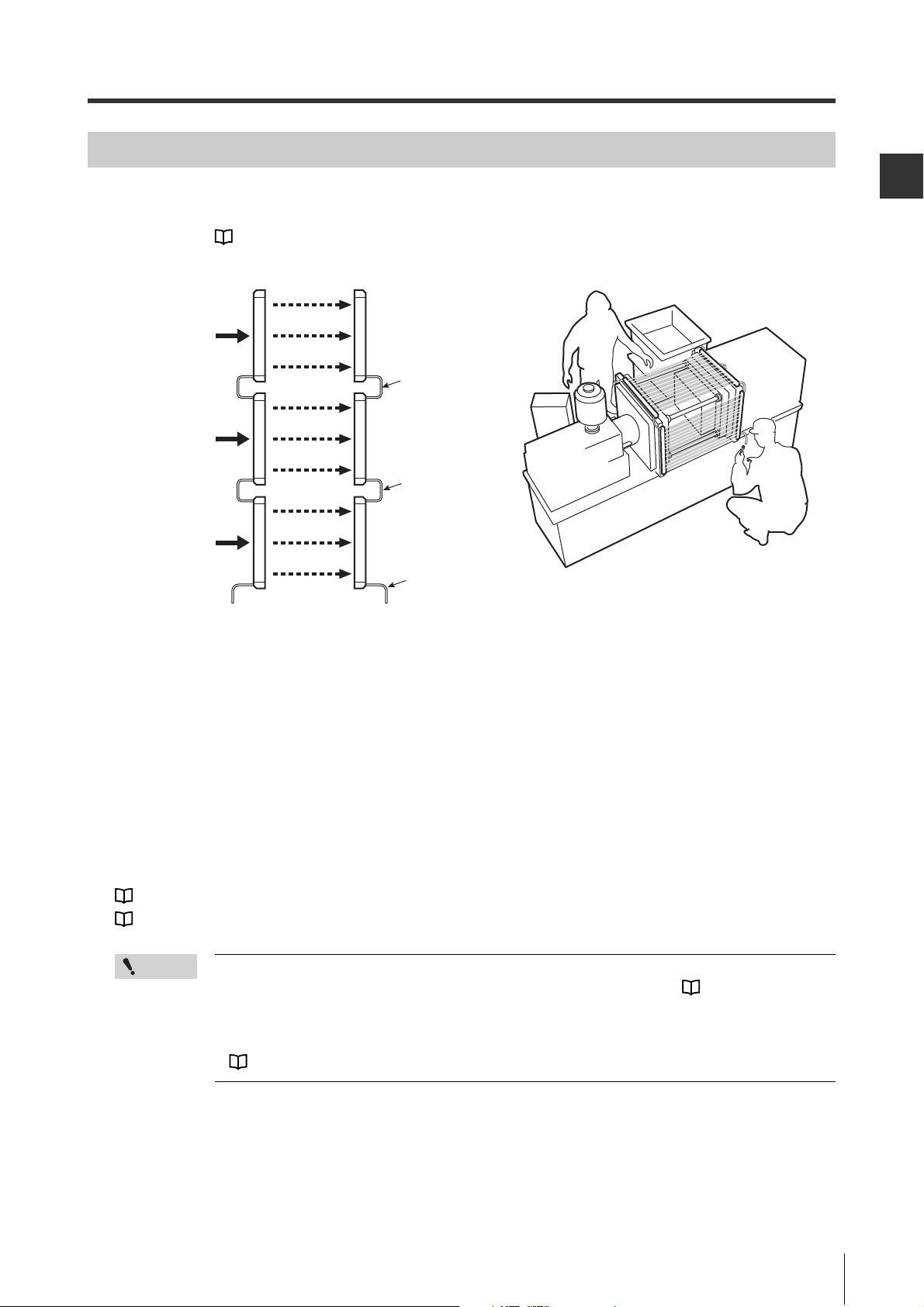
3-8 Optical Alignment .................................................................................................. 3-22
Ensure the following prior to optical alignment .......................................................................... 3-22
Alignment procedure ................................................................................................................. 3-22
Chapter 4 Wiring
4-1 Precautions on Wiring and Power Supply ............................................................ 4-2
Power supply ............................................................................................................................... 4-2
4-2 I/O Circuit Diagram .................................................................................................. 4-3
4-3 Cable Color and Pin Position ................................................................................. 4-4
Pin position .................................................................................................................................. 4-4
4-4 Cable Specification ................................................................................................. 4-6
4-5 Examples of Wiring ................................................................................................. 4-7
Symbols ....................................................................................................................................... 4-7
Optical synchronization system ................................................................................................... 4-8
One-line system ......................................................................................................................... 4-10
Wire synchronization system ..................................................................................................... 4-12
10
GL-RHG-M-NO0-E
Page 13

Chapter 5 Indicators
5-1 Function Indicators and 7-segment Display ......................................................... 5-2
Function indicators ...................................................................................................................... 5-2
7-segment display ....................................................................................................................... 5-3
5-2 Center Indicator ....................................................................................................... 5-4
Overview ...................................................................................................................................... 5-4
Changing the Indication Method for the Center indicator ............................................................ 5-4
Chapter 6
6-1 Before Use ............................................................................................................... 6-2
6-2 Installing the configuration software .................................................................... 6-3
6-3 Connecting the GL-RHG Main Unit and PC .......................................................... 6-5
6-4 Main Screen Part Names ........................................................................................ 6-7
6-5 Starting and Exiting the GL-R Configurator ......................................................... 6-9
Monitoring method Using the Configuration Software
About the configuration software ................................................................................................. 6-2
System Requirements ................................................................................................................. 6-2
Before Installation ........................................................................................................................ 6-3
Downloading the configuration Software ..................................................................................... 6-3
Installation Procedure .................................................................................................................. 6-4
Uninstalling each software ........................................................................................................... 6-4
Note for Windows Vista/7 ............................................................................................................ 6-4
Part Names .................................................................................................................................. 6-5
Connection Method ..................................................................................................................... 6-6
Menu bar ..................................................................................................................................... 6-7
Tool bar ....................................................................................................................................... 6-7
Tab .............................................................................................................................................. 6-8
Main area ..................................................................................................................................... 6-8
Starting the <GL-R Configurator> ................................................................................................ 6-9
Exiting the <GL-R Configurator> ............................................................................................... 6-11
GL-RHG-M-NO0-E
6-6 Saving the Configuration Data ............................................................................. 6-12
Saving the configuration data .................................................................................................... 6-12
Opening the saved configuration ............................................................................................... 6-12
6-7 Configuration Tab ................................................................................................. 6-13
6-8 Monitor Tab ........................................................................................................... 6-14
I/O monitoring ............................................................................................................................ 6-15
OFF information ......................................................................................................................... 6-16
Error information ........................................................................................................................ 6-17
6-9 Other Functions ..................................................................................................... 6-18
File (F) ....................................................................................................................................... 6-18
Communication (C) .................................................................................................................... 6-19
Log-in authentication (A) ........................................................................................................... 6-20
Language (L) ............................................................................................................................. 6-20
Help (H) ..................................................................................................................................... 6-20
11
Page 14

Chapter 7 Specifications and Dimensions
7-1 Nomenclature of Model Name ................................................................................ 7-2
Transmitter and receiver unit ....................................................................................................... 7-2
Cable ........................................................................................................................................... 7-2
7-2 Specifications .......................................................................................................... 7-3
Specifications .............................................................................................................................. 7-3
Response time (OSSD) ............................................................................................................... 7-5
Current consumption ................................................................................................................... 7-6
Weight ......................................................................................................................................... 7-6
Packaged items and materials .................................................................................................... 7-8
7-3 Dimensions ............................................................................................................ 7-10
GL-RHG unit .............................................................................................................................. 7-10
Adjustable angle mounting bracket (Model: GL-RB01) ............................................................. 7-11
Adjustable angle mounting bracket (Model: GL-RB02) ............................................................. 7-11
Straight mounting bracket (Model: GL-RB11) ........................................................................... 7-12
L-shaped mounting bracket (Model: GL-RB12) ......................................................................... 7-12
No dead zone mounting bracket (Model: GL-RB21) ................................................................. 7-13
Antivibration bracket for the adjustable angle mounting bracket (Model: GL-RB32) ................. 7-13
Antivibration bracket for the straight mounting bracket (Model: GL-RB31) ............................... 7-14
Interface unit (Model: GL-R1UB) ............................................................................................... 7-15
Appendix
1 Troubleshooting ......................................................................................................A-2
2 Checklist ..................................................................................................................A-7
Error condition .............................................................................................................................A-2
If the device is in the error condition ............................................................................................A-4
If the GL-RHG is not in an error condition ...................................................................................A-6
Checklist before operation ...........................................................................................................A-7
12
GL-RHG-M-NO0-E
Page 15

1
Before Use
1-1 Products . . . . . . . . . . . . . . . . . . . . . . . . . . . . . . . . . . . . . . . . . 1-2
1-2 Part Description. . . . . . . . . . . . . . . . . . . . . . . . . . . . . . . . . . . 1-8
GL-RHG-M-NO1-E
1-1
Page 16
1
1-1 Products
Brown and blue: AWG22 (nominal cross-sectional area of 0.34 mm2)
Others: AWG26 (nominal cross-sectional area of 0.14 mm2)
Before Use
Light curtain unit
• GL-RHG transmitter (Transmitter) × 1
• GL-RHG receiver (Receiver) × 1
• Test piece Diameter of 25 mm, Length of 200 mm × 1
• Instruction manual
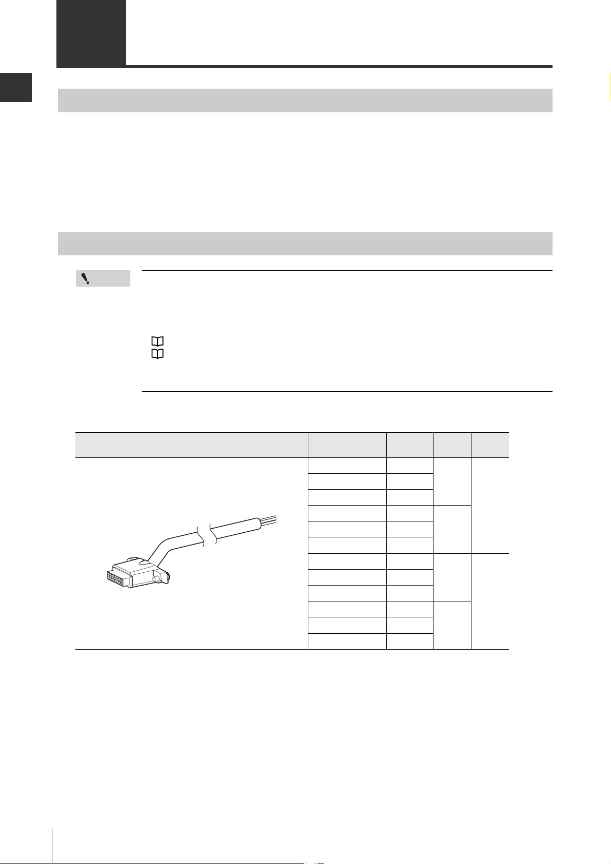
Cables
Point
• Each model is connected to one cable. Therefore, at least two cables are needed as a
system, one for the transmitter and another for the receiver.
• All cables can be used for both the transmitter and receiver.
• The combination of the wiring system and cable determines the functions that can be used.
Different types of cables can be used for the transmitter and receiver.
"2-1 Wiring System" (page 2-2)
"2-2 Functions" (page 2-4)
• Be sure to match the numbers of conductors (core wires) when using the unit connection
cable for extension use and the extension cable.
Unit connection cable
Shape Model
Number
of core
GL-RP5P 5
GL-RP5PS 7
GL-RP5PM 11
GL-RP10P 5
GL-RP10PM 11
GL-RP5N 5
GL-RP5NS 7
GL-RP5NM 11
GL-RP10N 5
GL-RP10NM 11
Length
5 m
10 mGL-RP10PS 7
5 m
10 mGL-RP10NS 7
Output
type
PNP
NPN
1-2
GL-RHG-M-NO1-E
Page 17

1
Unit connection cable (for extension use)
5-core: M12 connector (5 pins, male)
7-core: M12 connector (8 pins, male)
11-core: M14 connector (12 pins, male)
Brown and blue: AWG22 (nominal cross-sectional area of 0.34 mm2)
Others: AWG26 (nominal cross-sectional area of 0.14 mm2)
5-core: M12 connector (5 pins, female)
7-core: M12 connector (8 pins, female)
11-core: M14 connector (12 pins, female)
Two connectors are identical.
Direction of connection is not specified.
Used together with the extension cable.
1-1 Products
Before Use
Shape Model
GL-RPC03P 5
GL-RPC03PM 11
GL-RPC03N 5
GL-RPC03NM 11
Extension cable
Used together with the unit connection cable for extension use.
Shape Model
GL-RC5 5
GL-RC5S 7
GL-RC5M 11
GL-RC10 5
GL-RC10M 11
GL-RC20 5
GL-RC20M 11
Number
of core
Number
of core
Length
0.3 m
Length
5 m
10 mGL-RC10S 7
20 mGL-RC20S 7
Output
type
PNPGL-RPC03PS 7
NPNGL-RPC03NS 7
Output
type
PNP/
NPN
Series connection cable
Used for one-line system or series connection.
"Wiring system" (page 2-2)
"Series connection" (page 2-3)
Shape Model Length
GL-RS008 0.08 m
GL-RS015 0.15 m
GL-RS05 0.5 m
GL-RS1 1 m
GL-RS3 3 m
GL-RS5 5 m
GL-RS10 10 m
Output
type
PNP/
NPN
GL-RHG-M-NO1-E
1-3
Page 18
Before Use
1
DANGER
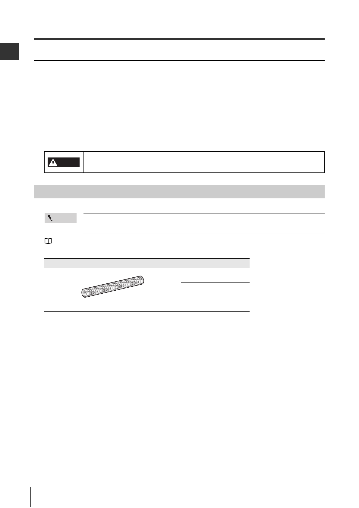
Outside diameter 20 mm, Inside diameter 15.3 mm Black
1-1 Products
Cable length specification
1. Optical synchronization system, wire synchronization system
The sum of the length of unit connection cable and extension cable must be 30 m or less. This limitation applies separately to the entire transmitter cable setup and the entire receiver cable setup. There
is no limitation for the total length of series connection cables when the GL-RHG is connected in
series.
2. One-line system
The sum of the length for all cables including unit connection cable, extension cable and series connection cable must be 30 m or less.
Cables must be within the lengths specified. Failure to follow this specification may cause
improper operation of safety functions, and may create a dangerous situation.
Cable protection pipe
Point
When using GL-RHG as a press machine and sharing machine (paper cutting machine) safety
device in Japan, make sure to use cable protection pipes.
"Attaching the Cable Protection Pipe" (page 3-16)
Shape Model Length
OP-87700 1 m
OP-87701 5 m
OP-87702 20 m
1-4
GL-RHG-M-NO1-E
Page 19
1-1 Products
1
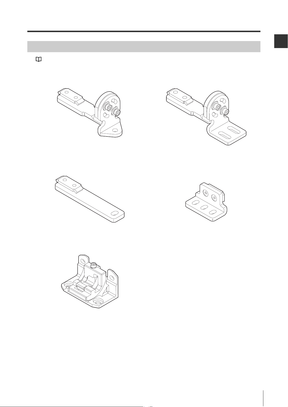
Mounting brackets
"3-7 Mounting Brackets" (page 3-17)
Adjustable angle mounting bracket
(GL-RB01)
Materials: SPHC
Straight mounting bracket
(GL-RB11)
Materials: SPHC
Adjustable angle mounting bracket
(GL-RB02)
Materials: SPHC
L-shaped mounting bracket
(GL-RB12)
Materials: SPHC
Before Use
No dead zone mounting bracket
(GL-RB21)
Materials: Zinc die-cast
GL-RHG-M-NO1-E
1-5
Page 20
1-1 Products
1
Before Use
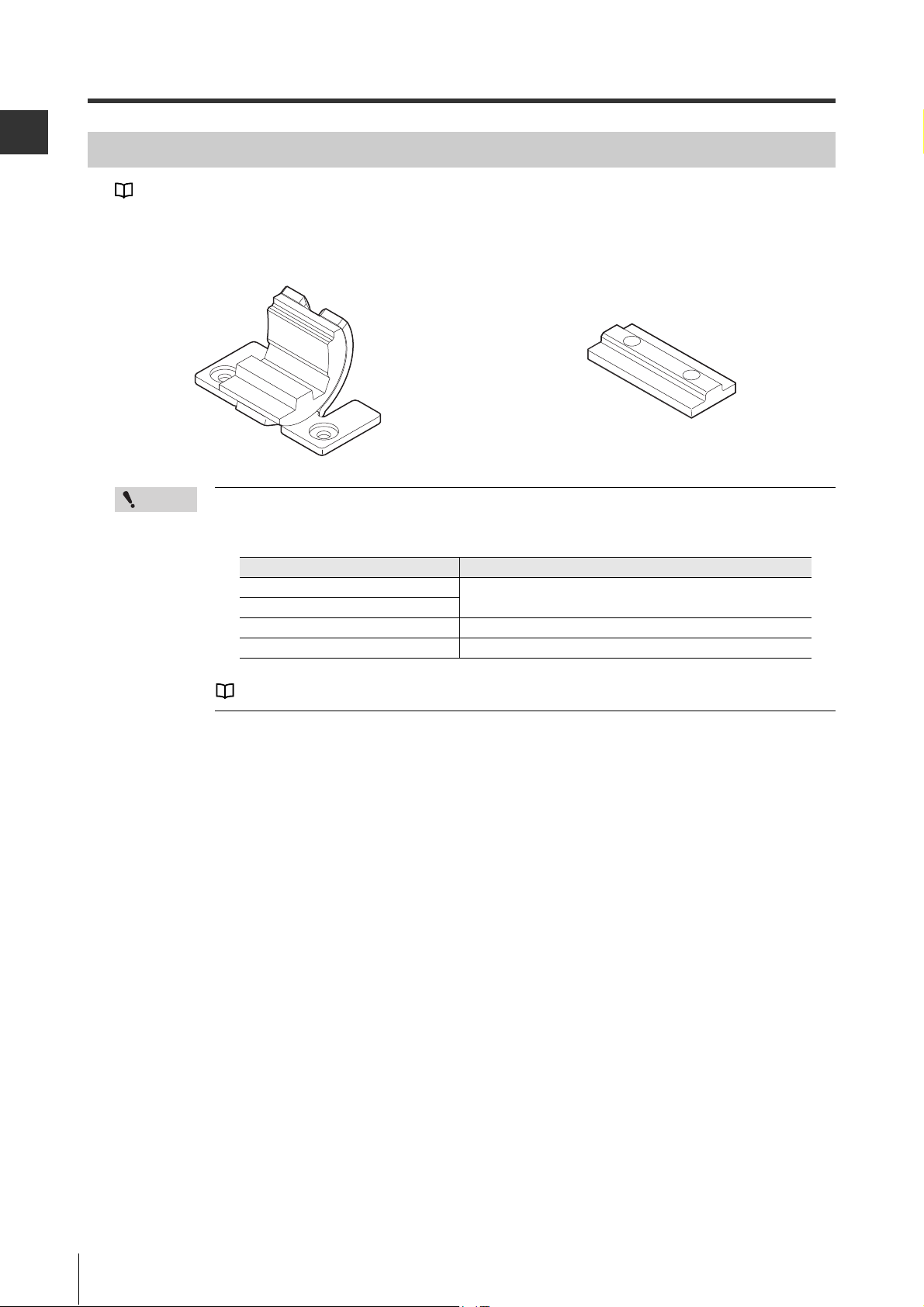
Antivibration bracket
"3-7 Mounting Brackets" (page 3-17)
Antivibration bracket for the adjustable
angle mounting bracket (GL-RB32)
Materials: SPHC, EPDM
Point
If the length for a single GL-RHG unit is 1280 mm or greater, use the following antivibration
bracket additionally as an intermediate support bracket. The antivibration bracket must be
selected according to the mounting bracket and installed on the center of the GL-RHG unit.
Mounting bracket Antivibration bracket
Adjustable angle mounting bracket
No dead zone mounting bracket
Straight mounting bracket Antivibration bracket for the straight mounting bracket
L-shaped mounting bracket L-shaped mounting bracket
Antivibration bracket for the straight
mounting bracket (GL-RB31)
Materials: EPDM
Antivibration bracket for the adjustable angle mounting bracket
For more information about the mounting position of the antivibration brackets, see
"Dimensions" (page 7-10).
1-6
GL-RHG-M-NO1-E
Page 21
1-1 Products
1
Relay terminal to convert control output to contact relay. Connection
between GL-RHG and GL-T11R is made using the dedicated connector
cable.
Each I/O line of GL-RHG is assigned to each terminal block of GL-T11R.
For details, refer to "GL-T11R Instruction Manual".
Software and Interface Unit
Required options when monitoring GL-RHG on a PC
"Chapter 6 Monitoring method Using the Configuration Software" (page 6-1)
Point
Configuration software <Safety Device Configurator>
The configuration software can be downloaded from the KEYENCE website.
http://www.keyence.com
If you can not access the internet, call the nearest KEYENCE office.
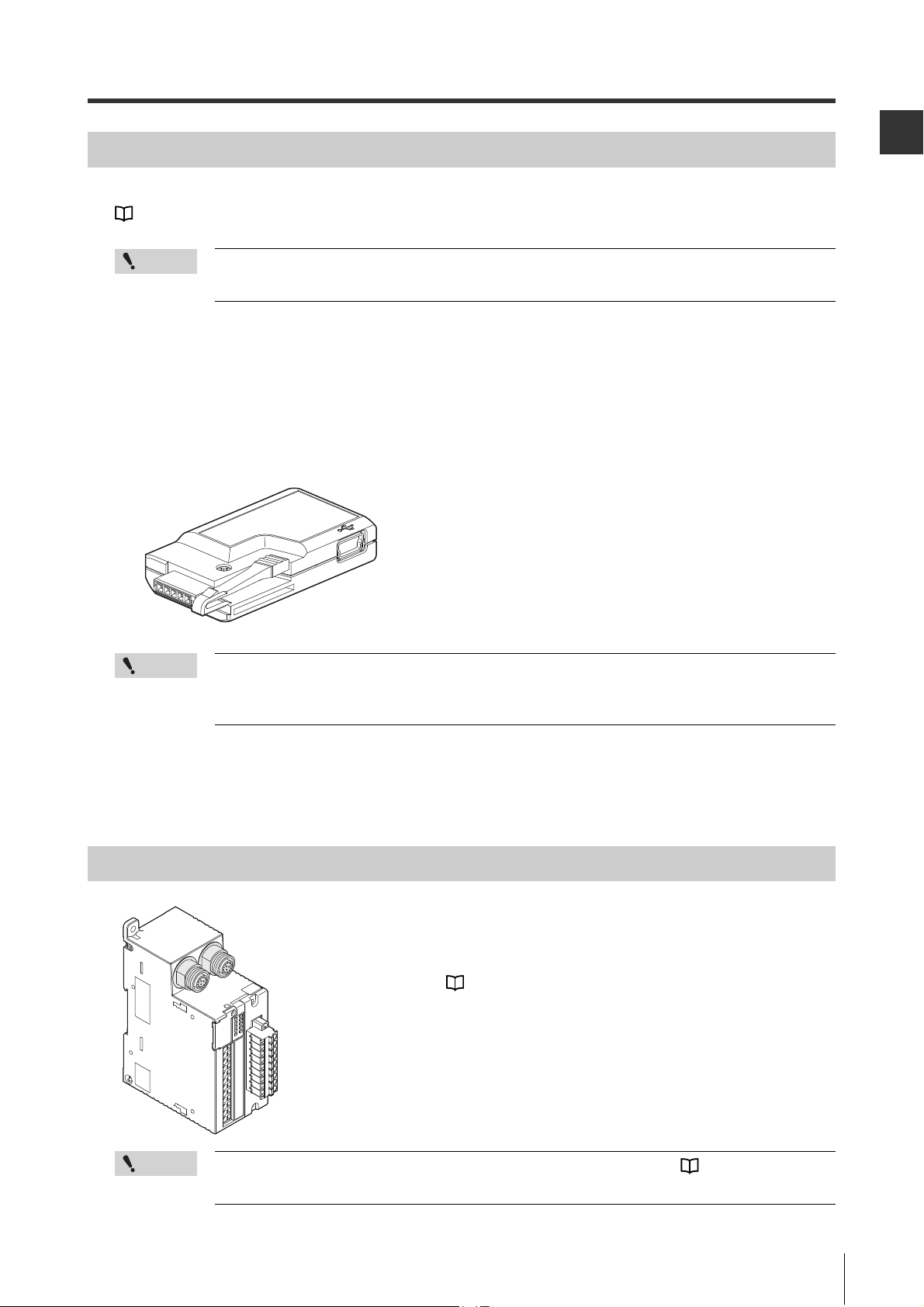
Interface unit (GL-R1UB)
Configuration data created by the configuration software cannot be uploaded to GL-RHG.
The configuration software can only monitor GL-RHG.
Before Use
Point
USB cable to connect the interface unit and the personal computer is not supplied. Please
acquire [A: miniB] type USB cable on yourself.
(You can also use the following option USB cables)
USB cable 2 m (OP-51580)
USB cable 5 m (OP-86941)
Dedicated Safety Reley for the GL-R Series (Model: GL-T11R)
Point
For connection between GL-RHG and GL-T11R, the cable shown on "Cables" (page 1-2)
cannot be used.
GL-RHG-M-NO1-E
1-7
Page 22
Before Use
1
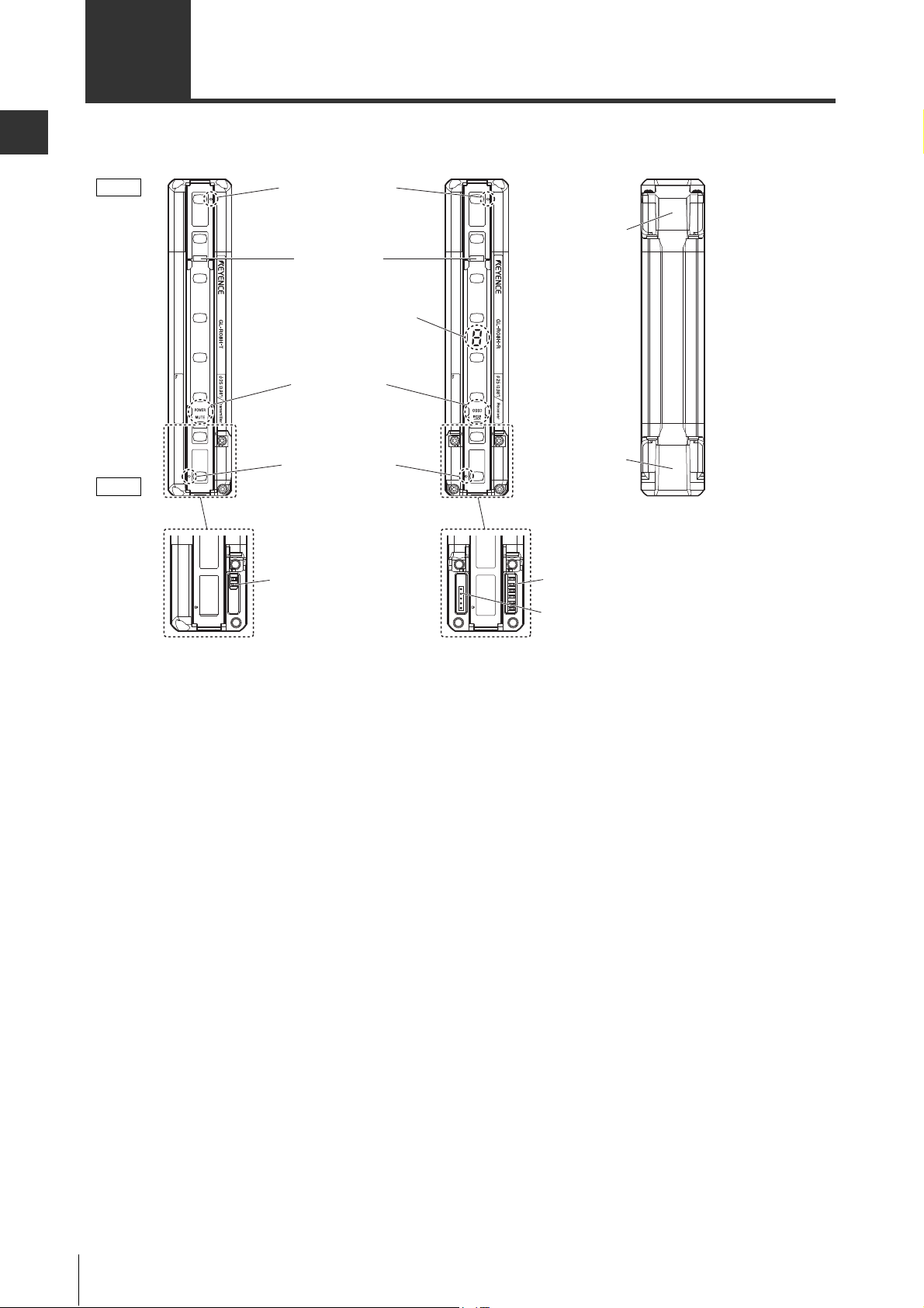
Transmitter Receiver Back side
End cover
Connector for the
unit connection
cable
Setting switch
(2 switches)
Setting switch
(6 switches)
Connector for the interface unit
(GL-R1UB)
To p
Beam center-line mark
Center Indicators
7-segment display
Function indicators
Beam center-line mark
Bottom
1-2 Part Description
*1 The side where the end cover has already been installed at shipment is the top side.
1-8
GL-RHG-M-NO1-E
Page 23
1
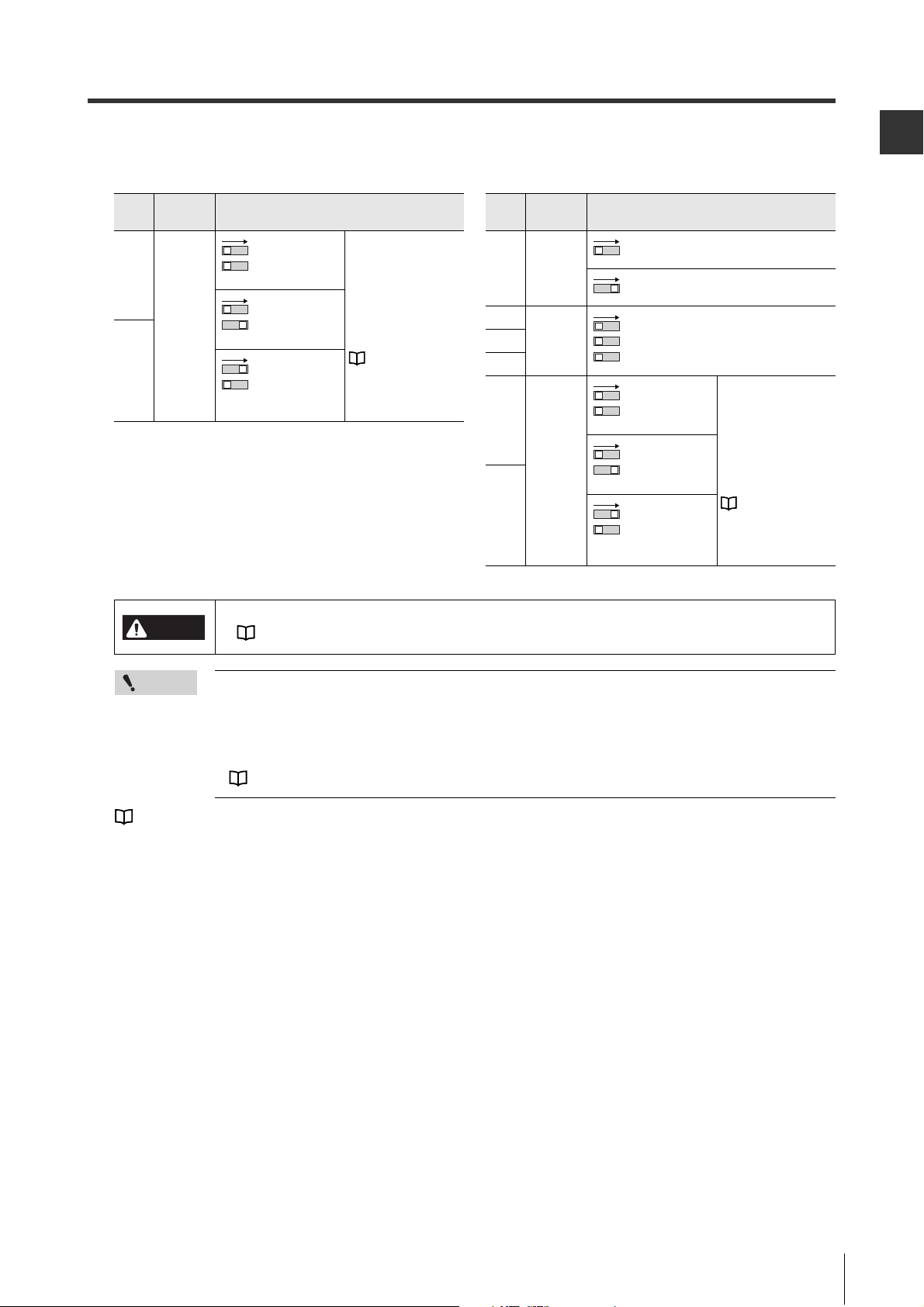
Setting switch
Transmitter Receiver
Switch
No.
Function Configuration
2
Channel
Channel 0
(Not applied)
(Default)
Use Channel for light
interference
prevention when
optical
synchronization
system is applied.
For details, refer to
"Light
Interference
Prevention Function"
(page 3-11)
Channel A
1
Channel B
2
Switch
No.
Function Configuration
6
Center
indicator
ON (Green) when all beam axes are
clear (Default).
OFF when all beam axes are clear.
(Green OFF)
5
Not in use
Do not change from the default
position.
4
3
2
Channel
Channel 0
(Not applied)
(Default)
Use Channel for light
interference
prevention when
optical
synchronization
system is applied.
For details, refer to
"Light
Interference
Prevention Function"
(page 3-11)
Channel A
1
Channel B
1-2 Part Description
Before Use
DANGER
Point
2
1
2
1
66
5
43
2
1
2
1
2
1
• The response time varies according to the configuration of Channel.
"Response time (OSSD)" (page 7-5)
• The configuration of the setting switch is applied when the power is supplied.
• When the GL-RHG is in series connection, the setting switch configuration of the main unit
is applied regardless of the setting switch configuration of the sub unit.
• When the GL-RHG operates in wire synchronization system, the setting switch for Channel
must be configured by default. Otherwise an error occurs.
"Wiring System" (page 2-2)
"Center Indicator" (page 5-4)
GL-RHG-M-NO1-E
1-9
Page 24
Before Use
1
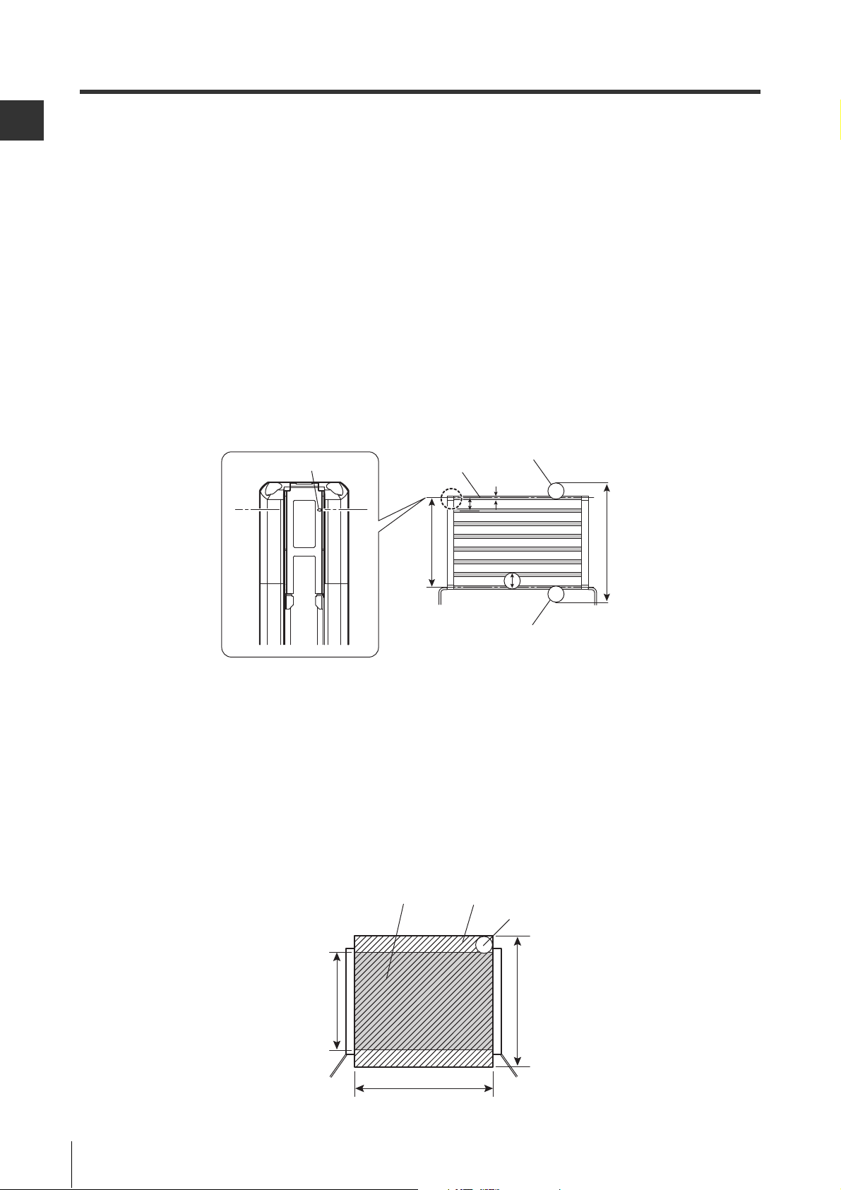
Beam center-line mark
Beam center-line
Specified target detection
capability (position A)
Specified target detection
capability (position B)
Protective
height
a: Beam axis spacing
b: Beam axis diameter
c: Detection capability
a
b
c
Detection
height
Protective zone Detection zone
Specified target detection capability
Protective height Detection height
Operating distance
1-2 Part Description
Beam center-line: An optical path joining the optical center of the emitting element on the transmitter to
the optical center of the corresponding receiving element on the receiver. The
GL-RHG must be installed so that the beam center-line mark on the transmitter and
that on the receiver face one another and are located at the same height.
Protective height: The height from the top beam center-line to the bottom beam center-line (length).
Detection height:
An object approaching the protective zone from the top of the protective height is first
detected at point A, which is the distance of the detection capability from the top of the
protective height. The equivalent position on the bottom is called point B. The height from
the top edge of the specified target detection capability that exists at point A to the bottom
edge of the specified target detection capability that exists at point B is called the "detec-
tion height".
The following calculation formula can be defined:
Detection height = "Protective height" + (2 × "specified target detection capability") –
"beam axis diameter".
*
Refer to the following diagram for an explanation of beam center-line, protective height and detection height.
Protective zone: The zone in which the specified target detection capability can be detected. The detec-
tion zone of the GL-RHG indicates a square area formed with the protective height and
the operating distance. When an object of the specified target detection capability is
present in this area, the light of the GL-RHG is blocked, and then the OSSD goes to
OFF state.
Detection zone:
The square area formed with the detection height and the operating distance, which is
broader than the protective zone. When an object of the specified target detection capabil-
ity is present in this area, the light of the
OFF state.
* Refer to the following diagram for protective zone and detection zone.
GL-RHG
is blocked, and then the OSSD goes to
1-10
GL-RHG-M-NO1-E
Page 25

2
Functions and Features
2-1 Wiring System . . . . . . . . . . . . . . . . . . . . . . . . . . . . . . . . . . . . 2-2
2-2 Functions . . . . . . . . . . . . . . . . . . . . . . . . . . . . . . . . . . . . . . . . 2-4
2-3 OSSD . . . . . . . . . . . . . . . . . . . . . . . . . . . . . . . . . . . . . . . . . . . 2-5
2-4 External Device Monitoring (EDM Function). . . . . . . . . . . . 2-6
2-5 Temporary Suspension of Safety Function . . . . . . . . . . . . 2-7
2-6 Wait Input Function . . . . . . . . . . . . . . . . . . . . . . . . . . . . . . . 2-22
2-7 Non Safety-Related Outputs. . . . . . . . . . . . . . . . . . . . . . . . 2-23
GL-RHG-M-NO2-E
2-1
Page 26
2
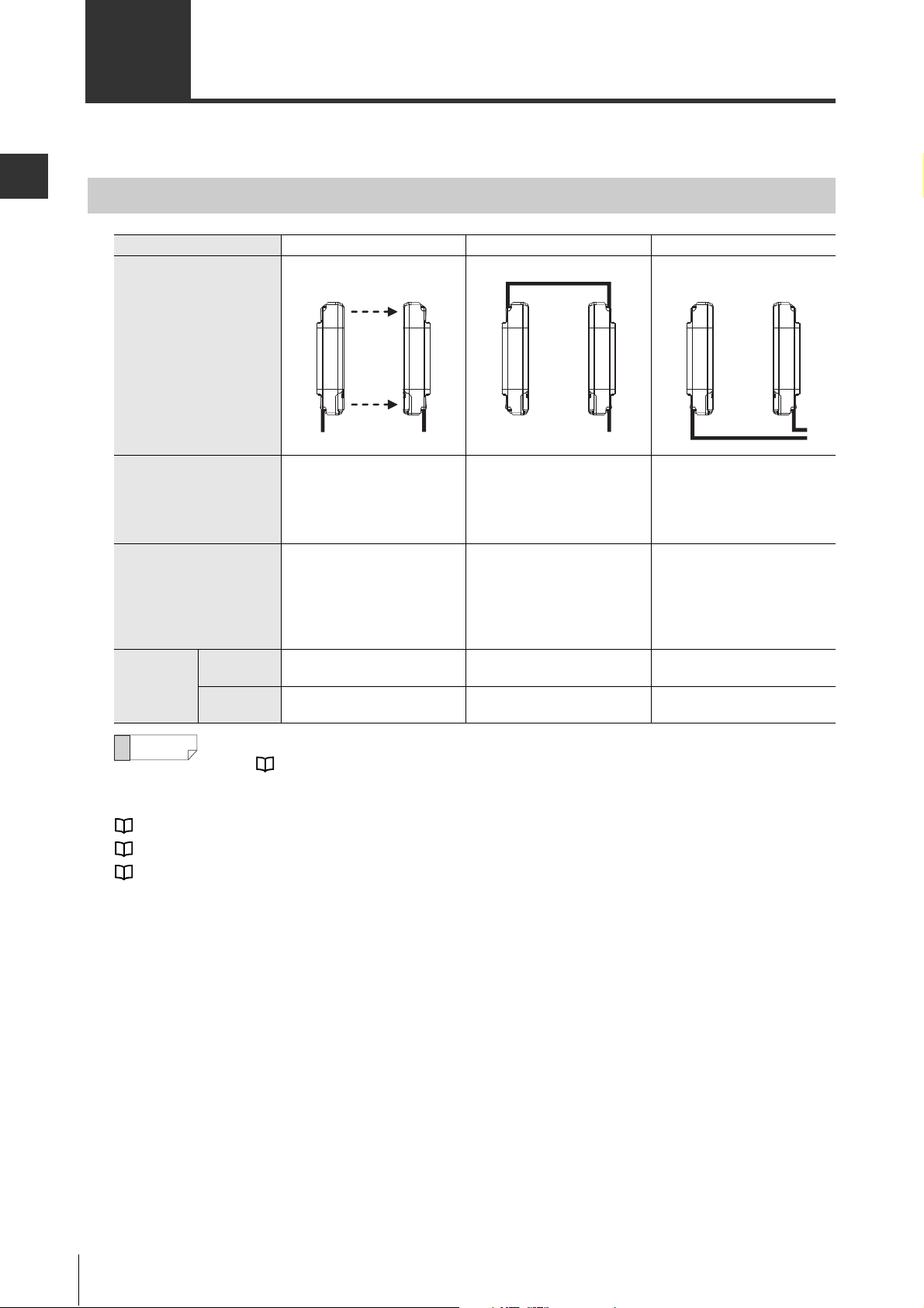
2-1 Wiring System
The following three types of wiring systems and the series connection are available in the GL-RHG series.
Functions and Features
Wiring system
Wiring system Optical synchronization system One-line system Wire synchronization system
Wiring diagram
Advantage
Limitation
Applicable
cable
Transmitter 5-core cable Series connection cable
Receiver
Transmitter Receiver Transmitter Receiver Transmitter Receiver
• Wiring is not needed between
the transmitter and receiver.
• The Transmitter and the
receiver can operate on
different power supplies.
• The input and output
functions on the transmitter
are not available.
• All indicators other than
"Power" are not available on
the transmitter.
5-core cable
11-core cable
• Simplified wiring.
• The unit connection cable is
not needed for the transmitter.
• The input and output
functions on the transmitter
are not available.
• There is a maximum limit for
the total length of cables.
5-core cable
11-core cable
• All functions of the GL-RHG
are available.
• Wiring is needed between the
transmitter and the receiver.
7-core cable
11-core cable
7-core cable
11-core cable
Reference
Available functions are determined according to the combination of the wiring system and cables.
Refer "2-2 Functions" (page 2-4) for the available function and select the wiring system and
cables.
"Cables" (page 1-2)
"2-2 Functions" (page 2-4)
"4-5 Examples of Wiring" (page 4-7)
2-2
GL-RHG-M-NO2-E
Page 27
2
Series connection
Example of use with 3 units in series connection
Series connection
cable
Series connection
cable
Unit connection cable
Sub unit 2
Sub unit 1
Main unit
Transmitter Transmitter Transmitter
Receiver Receiver Receiver
2-1 Wiring System
Up to three GL-RHG units can be serially connected and used as a single light curtain. The series connection is available in all wiring system. The series connection cables that KEYENCE provides as an
optional part. ( "Series connection cable" (page 1-3))
Benefits
Functions and Features
• Prevents light interference between the connected GL-RHGs
• Simplified wiring
Limitations
• Up to 3 units
• Up to 240 total number of beam axes (Up to 228 total number of beam axes when channel A or B is set
by selecting the optical synchronization system)
• When one-line wiring system is applied, the total length of unit connection cable, extension cable and
series connection cables must be 30 m or less.
"1-2 Part Description" (page 1-8)
"4-4 Cable Specification" (page 4-6)
Point
• Series connection is required for secure light interference prevention. When not connecting
the GL-RHG units in series, install the units by referring to "Light Interference
Prevention Method" (page 3-11)
• If the response time (ON OFF) exceeds 20 ms, this unit cannot be used as a certified
product based on the Chinese standard GB 4584 "压力机用光电保护装置技术条件".
"Response time (OSSD)" (page 7-5)
GL-RHG-M-NO2-E
2-3
Page 28

2
2-2 Functions
The wiring system and the type of cable used with the GL-RHG determine the functions that can be used.
Functions and Features
Wiring system
Cable
combination
Available
function
: Available without the configuration software
: Available with the configuration software
Output a signal when an error occurs. Error output function 2-24
Output a signal for monitoring by the PLC. AUX output function 2-23
Suspend the GL-RHG's safety functions temporarily while the workpiece is passing
through the detection area.
Suspend the GL-RHG's safety functions temporarily in order to activate the machine
while the workpiece remains in the detection area.
Separate the power supplies for the transmitter and receiver which are located far
away from each other.
Make sure whether the beam axes are optically aligned. Monitoring function 6-14
Cable for the transmitter 5-core
Cable for the receiver 5-core
OSSD output 2-5
AUX (auxiliary) output 2-23
Error output 2-24
Muting function 2-7
Muting lamp output 2-24
Override function 2-20
EDM function 2-6
Wait input 2-22
Reset input (for error) A-4
Channel configuration
(Light interference prevention
function)
Center indicator configuration 5-4
Monitoring function 6-14
Requirement Function Page
Optical
synchronization
11-core
3-11
One-line Wire synchronization
Series
connection
5-core
11-core
7-core 11-core
7-core
11-core
Muting function 2-7
Override function 2-20
Optical synchronization 2-2
7-core
11-core
Page
2-4
GL-RHG-M-NO2-E
Page 29
2
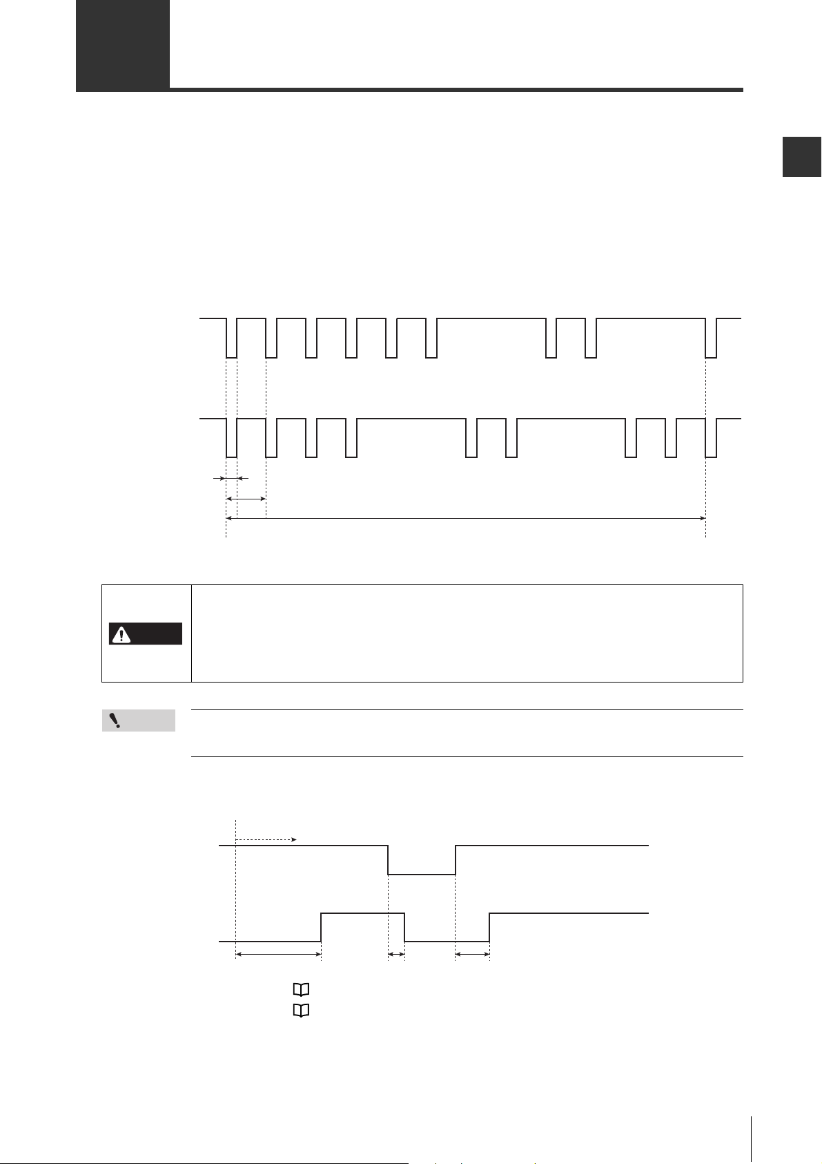
2-3 OSSD
OSSD 1
ON
640 to 940ms
A
OFF
A : 50 to 250s
B : 53 to 79ms
OSSD 2
ON
OFF
B
GL-R
OSSD
Clear
ON
OFF
Approx. 3 sec.
Start-up
Blocked
T1 T2
The OSSD is a safety-related control output. It connects to an external device (load), such as an FSD or
MPCE. The GL-RHG generates self-diagnosis signals on its internal control circuit to perform diagnostics
on the output circuit (OSSD). These signals periodically force the OSSD into a temporary OFF state when
no interruption exists in the protective zone.
If the internal control circuit receives a feed-back signal (OFF signal) based on the self-diagnosis, the
GL-RHG determines that its output circuit is operating normally. If this OFF signal is not returned to the
internal control circuit, the GL-RHG determines that there is a problem in its output circuit or wiring and
goes to the error condition.
Functions and Features
For the wiring between the GL-RHG and the safety-related part of a machine control system,
both OSSD 1 and OSSD 2 must always be wired to a safety-related part of the machine
DANGER
control system in order to ensure safety. If only one OSSD is wired to the safety-related part
of a machine control system, it results in significant harm to the machine operators,
including serious injury or death, if OSSD malfunction were to occur.
Point
The devices connected to the OSSD, such as safety relay or contactor, should not respond to
these temporary, self-diagnostic OFF-signals.
Time chart
T1: ON to OFF Response time "Response time (OSSD)" (page 7-5)
T2: OFF to ON Response time "Response time (OSSD)" (page 7-5)
GL-RHG-M-NO2-E
2-5
Page 30
Functions and Features
2
When using a PNP output type cable When using an NPN output type cable
Brown
Red/Black
Blue
GL-RHG
Receiver
+24 V
0 V
Device 1
Device 2
Short-circuit current: 10 mA
Brown
Red/Black
Blue
GL-RHG
Receiver
+24 V
0 V
Device 1
Device 2
Short-circuit current: 10 mA
GL-RHG
OSSD
External device
(B contact)
Response time (ON to OFF) Response time (ON to OFF)
Error condition
Specified
period of time
0.3 s
Specified
period of time
0.3 s
(1) (2)
Clear
Blocked
ON
OFF
ON
OFF
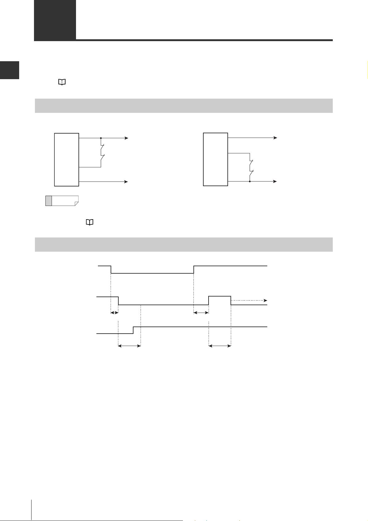
2-4
External Device Monitoring (EDM Function)
EDM (External Device Monitoring) is a function of the GL-RHG that monitors the state of the control
devices which are externally connected to the GL-RHG. The GL-RHG can detect a fault, such as welded
contacts on external devices, as long as the EDM function is activated.
See "Functions" (page 2-4) for the information of wiring system and cable type to activate this function.
Wiring
Reference
When using the 11-core cable and not using the EDM function, short-circuit the EDM input to AUX
output (Red wire on the receiver).
"4-5 Examples of Wiring" (page 4-7)
Time chart
(1) If the GL-RHG detects the operation of the external devices within the specified period of time (0.3 s)
after the operation of OSSD (ON to OFF, or OFF to ON), the GL-RHG continues normal operation.
(2) Unless the GL-RHG detects the operation of an external device within the specified period of time
(0.3 s) after the operation of OSSD (ON to OFF, OFF to ON), the GL-RHG goes into an error condition due to an EDM error.
2-6
GL-RHG-M-NO2-E
Page 31

2
2-5
DANGER
Temporary Suspension of Safety Function
Muting function
The muting function is used to temporarily suspend the GL-RHG's safety functions while the GL-RHG system meet the specified condition for muting. Before this function can be used, the outputs from the muting
devices must be connected to the muting input terminal on the GL-RHG.
In addition, the configuration software provides the user with the opportunity to select the beam axes to be in
the muted condition.
See "Functions" (page 2-4) for the information of wiring system and cable type to activate this function.
Point
For more specific examples of operations or for information about installation when using the
muting function. "Example: Muting function with 2 muting devices (Sensors)" (page 2-10)
• Since the muting function temporarily suspends the safety functions of the GL-RHG,
additional safety measures are required for the entire machine on which the GL-RHG is
installed. This is to ensure safety while the muting function is activated.
• The muting devices, the installation of those devices and the procedure to activate the
muting function must fulfill the conditions specified in this user's manual and the
requirements of the laws, rules, regulations, and standards in the country or region in
which the GL-RHG and those devices are used. Failure to follow this warning may result
in significant harm to the machine operators, including serious injury or death.
• When you install the muting devices (such as sensors or switches), the following
conditions must be fulfilled.
(1) Muting devices must be installed so that the muting function cannot be activated if the
machine that the GL-RHG is on is in the middle of a hazardous cycle or period.
(2) Muting devices must be installed so that the muting function cannot be activated by
personnel approaching the protective zone of the GL-RHG.
• Only responsible personnel should be allowed to install or wire the muting function or
muting devices.
• The muting devices must be installed in such a way that only responsible personnel can
change the installation or orientation by requiring special tools or keys to access the
devices.
• The whole responsibility for use of the muting function must rest with the customer.
Those who use the muting function must fulfill all of the requirements related to muting
functions. KEYENCE accepts NO responsibility or liability for any damage or injury due to
unauthorized installation, unauthorized usage or maintenance methods that are not
specified in this user's manual and/or due to noncompliance with the laws, rules,
regulations and standards set fourth by the country or region in which the GL-RHG is
used.
• The installation of a muting lamp may be required by the laws, rules, regulations, and
standards in the country or region in which the GL-RHG is used if you apply the muting
function. It depends on the machine application and/or the result of your risk assessment.
If it is necessary for you to provide the muting lamp, you must fulfill the requirements
because you are fully responsible for installation of the muting lamp.
Functions and Features
GL-RHG-M-NO2-E
2-7
Page 32

2-5 Temporary Suspension of Safety Function
2
Devices used for muting function
Functions and Features
Muting device
• The muting device output must be N.O. (normally open).
• A PNP output muting device is required when using the PNP output type cable and an NPN output mut-
ing device is required when using the NPN output type cable. The muting device must be capable of 2 to
3 mA current.
• Do not use one muting device with multiple outputs in place of two or more muting devices. (Only one
output per one muting device must be used.)
• If the muting device has a timer function that can adjust the output timing, do not use that function.
Muting lamp
When using the muting lamp, it must meet the following conditions.
For an incandescent lamp : rated 24 V DC, 1 to 5.5 W
For an LED indicator : rated current consumption must be 10 to 230 mA.
Detailed operation
Conditions for initiation of muting
Muted condition is initiated if all of the following conditions are met:
• Muting input 2 turns ON within 0.04 to 3 seconds after muting input 1 turns ON
• GL-RHG detects no interruption in the protective zone
• OSSD is in the ON state and remains for 0.5 seconds or more.
Conditions for termination of muting
Muted condition is terminated if one of the following conditions is met.
• Either of the muting inputs goes to the OFF state for at least 5 ms.
• Light curtain goes to an error condition
• Wait input goes to ON state
• The power supply is interrupted or restored.
• Maximum muting period of approx. 5 minutes has been passed.
Reference
When the GL-RHG is interrupted, the GL-RHG cannot go to the muted condition. In this case, you
can apply override function to suspend the safety functions temporarily. "Override function" (page
2-20)
2-8
GL-RHG-M-NO2-E
Page 33

2
Time chart
Muting input 1
Muting input 2
Muted condition
Not muted condition
Muting lamp
GL-RHG
OSSD
T1 T1No limit 5 ms max.
5 ms max.
90 ms max.
Within 5 min
90 ms max. 90 ms max.
Within 5 min
90 ms max.
Response time (ON to OFF) Response time (OFF to ON)
Clear
Blocked
ON
OFF
ON
OFF
ON
OFF
Light OFF
Light ON
T1: 0.04 to 3 seconds
2-5 Temporary Suspension of Safety Function
Functions and Features
Point
Reference
• If muting input 2 turns on outside the T1 range after muting input 1 turns on, the GL-RHG
will not mute and remains in normal operation. (The GL-RHG does not go into an error
condition.)
• If only muting input 1 or muting input 2 turn OFF and back ON, the GL-RHG will not return to
the muted condition. To return to the muted condition, both muting inputs 1 and 2 must first
turn OFF and the muting conditions must be met again.
• If the GL-RHG power is turned ON while the GL-RHG is in the muted condition or either
muting input 1 or 2 is on, the GL-RHG will not go to a muted condition. In this case, both
muting inputs must be turned OFF and the muting conditions must be met again.
• The function indicators and 7-segment display indicate each condition.
"Function Indicators and 7-segment Display" (page 5-2)
• If the GL-RHG does not go to muted condition when both muting input 1 and 2 are ON, all muting
condition are not met. The configuration software can show the conditions which are not met.
"I/O monitoring" (page 6-15)
GL-RHG-M-NO2-E
2-9
Page 34

2-5 Temporary Suspension of Safety Function
2
Workpiece
Sensor A2
Safety zone Hazardous zone
Receiver
Reflector
ReflectorSensor A1
Beam axis
Transmitter
GL-RHG
The beams from sensor
A1 and A2 must intersect
each other within the
hazardous zone.
L
V
D
Example: Muting function with 2 muting devices (Sensors)
Functions and Features
The following is an example of the muted condition while the workpiece is passing through the detection
area of the GL-RHG. In this example, 2 retro-reflective photoelectric sensors are used as the muting
devices (ON when the beam from the sensor is blocked).
Conditions for installation of muting devices
All 4 of the following conditions must be met in order to ensure a continuous muted condition while the
workpiece is passing through the detection area.
L (mm) : Length of the workpiece
D (mm) : Displacement distance between the point where the workpiece first interrupts each beam.
V (mm/s) : Workpiece speed
The activation time of muting input 1 and that of muting input 2 must be between 0.04 to 3 seconds.
(1) 0.04 < D / V < 3
(2) D < L
(3) Both sensor A1 and sensor A2 must be installed so that their beams intersect in the hazardous area.
(4) Both sensor A1 and sensor A2 must turn ON when the beam is blocked (Dark ON).
2-10
GL-RHG-M-NO2-E
Page 35

2
Explanation
(1) The workpiece is approaching the
protective zone but the GL-RHG
does not go into the muted condition because both muting input 1
and 2 are OFF. At this point, the
GL-RHG continues normal operation and OSSD goes OFF if the
GL-RHG gets interrupted.
Sensor A2
Safety zone Hazardous zone
Receiver
Reflector
ReflectorSensor A1
Beam axis
Transmitter
GL-RHG
Workpiece
Movement
(2)
The workpiece interrupts the beam
from sensor A1 first, and then interrupts the beam from sensor A2. The
GL-RHG then goes into the muted
condition and the OSSD does not
turn off even if the GL-RHG detects
an interruption.
Sensor A2
Safety zone Hazardous zone
Receiver
Reflector
ReflectorSensor A1
Beam axis
Transmitter
GL-RHG
Workpiece
Movement
(3) The GL-RHG goes back to nor-
mal operation (not muted) if either
sensor A1 or sensor A2 turns off
as the workpiece passes.
Sensor A2
Safety zone Hazardous zone
Receiver
Reflector
ReflectorSensor A1
Beam axis
Transmitter
GL-RHG
Workpiece
Movement
2-5 Temporary Suspension of Safety Function
Functions and Features
GL-RHG-M-NO2-E
2-11
Page 36

Functions and Features
2
When using the PNP output cable
Brown
Pink
(Muting input 1)
Blue
GL-RHG
Transmitter
+24 V
0 V
Sensor A1
Sensor A2
Red/Black
(Muting input 2)
Short-circuit current: 2.5 mA
When using the NPN output cable
Brown
Pink
(Muting input 1)
Blue
GL-RHG
Transmitter
+24 V
0 V
Sensor A1
Sensor A2
(Muting input 2)
Red/Black
Short-circuit current: 2.5 mA
Sensor A1
Sensor A2
Muting lamp
OSSD
Muted condition
Within approx. 5 min.
Within 0.04
to 3 s
90 ms max.90 ms max.
GL-RHG
ON
OFF
ON
OFF
ON
OFF
Clear
Blocked
Light ON
Not muted condition
Light OFF
2-5 Temporary Suspension of Safety Function
Wiring the muting inputs
Point
Time chart
Output type of the switch or sensor used as the muting device must be the same as the cable
used.
Example: PNP output if PNP cable is used, or NPN output if NPN cable is used.
Also, the muting device must be able to handle a 3 mA current load.
2-12
GL-RHG-M-NO2-E
Page 37

2-5 Temporary Suspension of Safety Function
2
Workpiece
Sensor
A1
Safety zone Hazardous zone
GL-RHG
Receiver
Beam
axis
Transmitter
L
V
D1
Sensor
A2
SensorB1Sensor
B2
D2
D3
Movement
Example: Muting function with 4 muting devices
The following is an example of the muted condition while the workpiece is passing through the detection
area of the GL-RHG. In this example, 4 thru-beam photoelectric sensors are used as the muting devices
(ON when the beam is blocked).
Setup conditions
All 4 of the following conditions must be met in order to ensure the continuous muted condition while the
workpiece is passing through the detection area.
Functions and Features
L (mm) : Length of the workpiece
D1, D2, D3 (mm) : The spacing between sensors
V (mm/s) : Workpiece speed
The activation time of muting input 1 and that of muting input 2 must be between 0.04 to 3 seconds.
(1) 0.04 < D1 / V < 3
(2) D2 < L
(3) D3 < L
(4) All of sensors A1, A2, B1 and B2 must turn ON when the beam is blocked (Dark ON).
GL-RHG-M-NO2-E
2-13
Page 38

Functions and Features
2
Sensor A2
Safety zone Hazardous zone
Receiver
Beam
axis
Transmitter
GL-RHG
Workpiece
Movement
Sensor B2
Sensor B1
Sensor A1
V
(1)
The workpiece is approaching the
protective zone but the GL-RHG
does not go into the muted condition because all of the sensors are
OFF. At this point, the GL-RHG
continues normal operation and the
OSSD goes OFF if the GL-RHG
gets interrupted.
(2) The workpiece interrupts the
beam of sensor A1, and turns ON
the output. However, the GL-RHG
still continues normal operation.
Sensor A2
Safety zone Hazardous zone
Receiver
Beam
axis
Transmitter
GL-RHG
Workpiece
Movement
Sensor B2
Sensor B1
Sensor A1
V
2-5 Temporary Suspension of Safety Function
Explanation
2-14
GL-RHG-M-NO2-E
Page 39

2-5 Temporary Suspension of Safety Function
2
(3)
The workpiece interrupts the beam
of sensor A1 first, and then interrupts the beam of A2. Then, the
GL-RHG goes into the muted condition and the OSSD does not turn
off even if the GL-RHG detects an
interruption.
Sensor A2
Safety zone Hazardous zone
Receiver
Beam axis
Transmitter
GL-RHG
Workpiece
Movement
Sensor B2
Sensor B1
Sensor A1
V
Movement
V
(4)
The workpiece is passing through
the detection area of the GL-RHG.
The GL-RHG still continues the
muted condition.
Sensor A2
Safety zone Hazardous zone
Receiver
Beam axis
Transmitter
GL-RHG
Workpiece
Sensor B2
Sensor B1
Sensor A1
(5)
The GL-RHG goes back to normal
operation (not muted) when sensor
B1 turns off after the workpiece has
been passed.
Movement
V
Sensor A2
Safety zone Hazardous zone
Receiver
Beam
axis
Transmitter
GL-RHG
Workpiece
Sensor B2
Sensor B1
Sensor A1
Functions and Features
GL-RHG-M-NO2-E
2-15
Page 40

Functions and Features
2
When using the PNP output cable
Brown
Pink
(Muting input 1)
Blue
GL-RHG
Transmitter
+24 V
0 V
Sensor
A1
Sensor
A2
Red/Black
(Muting input 2)
Short-circuit current: 2.5 mA
When using the NPN output cable
Sensor
B1
Sensor
B2
Brown
Light blue
(Muting input 1)
Blue
GL-RHG
Transmitter
+24 V
0 V
Sensor
A1
Sensor
A2
(Muting input 2)
Red/
Black
Short-circuit current: 2.5 mA
Sensor
B1
Sensor
B2
Sensor A1
Sensor A2
Muting lamp
OSSD
Not muted condition
Within approx. 5 min.
Within 0.04
to 3 s
90 ms max.
90 ms max.
GL-RHG
Sensor B1
Sensor B2
ON
OFF
Clear
Blocked
Light ON
Light OFF
ON
OFF
ON
OFF
ON
OFF
ON
OFF
Muted condition
2-5 Temporary Suspension of Safety Function
Wiring the muting inputs
Point
Time chart
The output type of the switch or sensor used as the muting device must be the same as the
cable used.
Example: PNP output if PNP cable is used, or NPN output if NPN cable is used.
Also, the muting device must be able to handle a 3 mA current load.
2-16
GL-RHG-M-NO2-E
Page 41

2-5 Temporary Suspension of Safety Function
2
Switches A1 and A2
must be N.O.
Switch A1 Switch A2
Cam
V
L
D
Example: Muting function with 2 muting devices (Switches)
The following is an example of the muted condition while the mold is going upward or at the top dead
center of the operation. In this example, 2 switches are used as the muting devices.
Setup conditions
All 4 of the following conditions must be met in order to ensure the continuous muted condition while the
mold is going upward or at the top dead center.
L (mm) : The length of a part of cam that switch can be ON
D (mm) : The spacing between switches
V (mm/s) : Cam speed
The activation time of muting input 1 and muting input 2 must be between 0.04 to 3 seconds.
(1) 0.04 < D / V < 3
(2) D < L
(3) Both switch A1 and switch A2 must be ON only while the mold is going upward or at top dead center.
(4) The total time the mold is going upward and the time while it is at the top dead center must be 5 min-
utes or less.
Functions and Features
GL-RHG-M-NO2-E
2-17
Page 42

Functions and Features
2
Switch A1 Switch A2
Cam
Switch A1 Switch A2
Cam
Switch A1 Switch A2
Cam
Switch A1 Switch A2
Cam
Switch A1 Switch A2
Cam
2-5 Temporary Suspension of Safety Function
Explanation
(1) The GL-RHG is not muted when the mold is at or stays at the bottom dead
center of the press cycle. At this point, the GL-RHG continues normal
operation and the OSSD goes OFF if the GL-RHG gets interrupted.
(2) When switch A1 turns ON first, and then switch A2 turns ON, the GL-RHG
goes into the muted condition and the OSSD does not turn OFF, even if the
GL-RHG detects an interruption.
(3) The GL-RHG continues the muted condition because both switches stay
turned ON and the mold continues to stay at the top dead center position.
(4) The GL-RHG will go back to normal operation (not muted) as soon as sen-
sor A1 turns OFF after the mold starts downward.
(5) The GL-RHG continues normal operation while the mold is going down-
ward.
2-18
GL-RHG-M-NO2-E
Page 43

2
Wiring the muting inputs
When using the PNP output cable
Brown
Pink
(Muting input 1)
GL-RHG
Transmitter
+24 V
Switch A1
Switch A2
Red/Black
(Muting input 2)
When using the NPN output cable
Blue
Pink
(Muting input 1)
GL-RHG
Transmitter
0V
Switch A2
Switch A1
(Muting input 2)
Red/Black
Sensor A1
Sensor A2
Muting lamp
OSSD
Not muted condition
Within approx. 5 min.
Within 0.04
to 3 s
90 ms max.90 ms max.
GL-RHG
ON
OFF
Clear
Blocked
Light ON
Light OFF
ON
OFF
ON
OFF
Muted condition
2-5 Temporary Suspension of Safety Function
Functions and Features
Point
Time chart
The output type of the switch or sensor used as the muting device must be the same as the
cable used.
Example: PNP output if PNP cable is used, or NPN output if NPN cable is used.
Also, the muting device must be able to handle a 3 mA current load.
GL-RHG-M-NO2-E
2-19
Page 44

2-5 Temporary Suspension of Safety Function
2
DANGER
Sensor A1
Safety zone Hazard zone
Receiver
Reflector
ReflectorSensor A2
Traveling direction
Beam axis
Transmitter
GL-RHG
Workpiece
Override function
Functions and Features
During normal operation, the OSSD goes to an OFF state if the muting function is deactivated and an
interruption remains in the protective zone of the GL-RHG. The OSSD OFF state will remain until the
obstruction is removed.
The Override Function allows a temporary manual suspension of the GL-RHG safety functions.
This makes it possible to remove the obstruction remaining in the protective zone of the GL-RHG.
(Machine is able to be manually operated on a temporary basis because the safety function of the
GL-RHG is temporarily suspended.)
See "Functions" (page 2-4) for the information of wiring system and cable type to activate this function.
• The override function allows a temporary manual suspension of the GL-RHG safety
functions. Thus, in order to ensure safety while the override function is activated,
additional safety measures are required for the entire machine system on which the
GL-RHG is installed.
• The devices, the installation of those devices, and the procedures to activate the override
function must fulfill the conditions specified in this user's manual as well as the
requirements of the laws, rules, regulations, and standards in the country or region in
which the GL-RHG and those devices are used. Failure to follow this warning may result
in significant harm to the machine operators, including serious injury or death.
• The override function allows a temporary manual suspension of the GL-RHG safety
functions. Manual operation devices are required to activate the override function. When
installing the devices to activate the override function, the devices must be installed so
that the whole hazardous zone can be checked by responsible personnel and that the
device operators are not in the hazardous zone.
• Be sure to confirm that there is nobody in the hazardous zone, before the override is
activated. Failure to follow this warning may result in significant harm to the machine
operators, including serious injury or death.
2-20
GL-RHG-M-NO2-E
Page 45

2-5 Temporary Suspension of Safety Function
2
DANGER
Muting input 1
Muting input 2
GL-RHG
Override input
Reset input
Muting lamp
OSSD
ON
OFF
Clear
Blocked
ON
OFF
ON
OFF
ON
OFF
Override condition
No override condition
ON
OFF
Light ON
Light OFF
No limit
No limit
Within approx. 60 s
Within
0.04 to 1 s
90 ms max.90 ms max.
• The installation of the indication for override may be required by the laws, rules,
regulations, and standards in the country or region in which the GL-RHG is used if you
apply the override function. It depends on the machine application and/or the result of
your risk assessment. If it is necessary for you to provide the indication for override, you
must fulfill the requirements because you are fully responsible for installation of the
indication for override.
• Only the responsible personnel must be allowed use or activation of the override
function.
• Those who use the override function must fulfill all requirements related to the override
function. KEYENCE accepts NO responsibility and NO liability for any damage or any
injury due to the unauthorized installation, usage, or maintenance, which are not
specified in this user's manual, and/or due to noncompliance with the laws, rules,
regulations and standards in the country or region in which the GL-RHG is used.
Conditions for initiation of override
The override condition is initiated if all of the following conditions are met and the wait input goes to the
ON state within 0.04 to 1 s after the override input turns ON.
• The GL-RHG is not an error condition.
• OSSD is in the OFF state.
• GL-RHG detects interruption in the protective zone. (One or more beam axis is blocked.)
• Either of muting inputs, or both, turns ON state.
Functions and Features
Conditions for termination of override
The override condition is terminated if one of the following conditions is met.
• All of muting inputs turn OFF
• Either the override input or wait input, or both, turn OFF.
• GL-RHG goes into the error condition.
• Maximum override period of approx. 60 seconds has been passed.
Time chart
GL-RHG-M-NO2-E
2-21
Page 46

Functions and Features
2
Point
Reference
When using a PNP output type cable When using an NPN output type cable
Brown
White
Blue
GL-RHG
Transmitter
+24 V
0 V
Short-circuit current: 2.5 mA
Brown
White
Blue
+24 V
0 V
Short-circuit current: 2.5 mA
GL-RHG
Transmitter
Wait input
GL-RHG
OSSD
60 ms max. 60 ms max.
ON
OFF
ON
OFF
No interruption
Interruption
2-6 Wait Input Function
The wait input is a NON-SAFETY-RELATED function.
This function puts the OSSD into an OFF state through a signal from an external device (non safetyrelated device).
See "Functions" (page 2-4) for the information of wiring system and cable type to activate this function.
How to use
(1) The signal from the external non safety-related control device is connected to the wait input. When
this signal is ON, the OSSD of the GL-RHG goes to OFF.
(2) This function is useful for testing and making sure that the machine which the GL-RHG is installed on
can stop within the specified period of time when the OSSD goes into an OFF state.
The wait output is not allowed to be connected to the safety output provided from the
DANGER
safety-related control system. Connection to the safety output of the safety-related control
system may result in significant harm to the machine operators including serious injury or
death.
Point
Wiring
Time chart
The OSSD goes into an OFF state when the wait input is activated while the GL-RHG is in the
muted condition. The GL-RHG returns to normal operation after the wait input is deactivated.
"Muting function" (page 2-7)
The switch must be rated at 24 V DC, 2 to 3 mA.
For the GL-RHG, the 7-segment display indicates "" if the wait input is activated.
See "Function Indicators and 7-segment Display" (page 5-2)
2-22
GL-RHG-M-NO2-E
Page 47

2
2-7 Non Safety-Related Outputs
OSSD
(1)
AUX
60 ms max.
60 ms max.
(2)
ON
OFF
ON
OFF
ON
OFF
The outputs other than the OSSD are "non safety-related outputs" which inform a PLC or similar nonsafety devices of the operations of the GL-RHG.
All non safety-related outputs other than the muting lamp output can be connected to both PNP and NPN
input devices. Refer to the time charts mentioned in this manual because the output logic is different
depending on the connected device. On the other hand, the muting lamp output is an NPN open collector
output.
"4-2 I/O Circuit Diagram" (page 4-3)
Available non safety-related outputs according to the cable type
Functions and Features
Cable type
5-core cable Nothing Nothing
7-core cable Error output Nothing
11-core cable Muting lamp output and error output AUX output
Available non safety-related outputs on the transmitter
Available non safety-related outputs on the receiver
The non safety-related outputs on the transmitter are available only when wired synchronization system is
applied. "1-2 Part Description" (page 1-8)
The non safety-related output is not allowed to be used as a safety output for safety-related
DANGER
control systems. The non safety-related output does not constitute a part of the safetyrelated control system. Usage of the non safety-related output as a safety output may result
in significant harm to the machine operators including injury or death.
AUX (Auxiliary) output (Receiver, red wire)
This output informs an external device (non safety-related device) of the operations of the GL-RHG and operates in synchronization with OSSD operation. It can only be connected to a PLC or similar non-safety
devices.
See "Functions" (page 2-4) for the information of wiring system and cable type to activate this function.
Time chart
(1) When using a PNP output type cable to connect to a PNP input device, or when using an NPN output
type cable to connect to an NPN input device
(2) When using a PNP output type cable to connect to an NPN input device, or when using an NPN output
type cable to connect to a PNP input device
GL-RHG-M-NO2-E
2-23
Page 48

2-7 Non Safety-Related Outputs
2
OSSD
(1)
Error output
ON
60 ms max.
Error condition
OFF
ON
OFF
(2)
ON
OFF
Error output (Transmitter, black wire)
Functions and Features
The error output is activated if the GL-RHG goes to the error condition.
See "Functions" (page 2-4) for the information of wiring system and cable type to activate this function.
Time chart
(1) When using a PNP output type cable to connect to a PNP input device, or when using an NPN output
type cable to connect to an NPN input device
(2) When using a PNP output type cable to connect to an NPN input device, or when using an NPN output
type cable to connect to a PNP input device
Muting lamp output (The red wire of the transmitter cable)
This output is available only when using an 11-core cable for the transmitter.
The muting lamp output is an output function to light up the muting lamp if the GL-RHG goes into the
muted condition or override condition. The muting lamp is used to indicate the condition of GL-RHG.
"Temporary Suspension of Safety Function" (page 2-7)
See "Functions" (page 2-4) for the information of wiring system and cable type to activate this function.
Muting lamp
When using the muting lamp, it must meet the following conditions.
For an incandescent lamp : rated 24 V DC, 1 to 5.5 W
For an LED indicator : rated current consumption must be 10 to 230 mA
Point
The muting lamp output is an NPN open collector output regardless of the cable type.
2-24
GL-RHG-M-NO2-E
Page 49

3
Installation to a Machine
3-1 Correct Installation Method . . . . . . . . . . . . . . . . . . . . . . . . . 3-2
3-2 Safety Distances . . . . . . . . . . . . . . . . . . . . . . . . . . . . . . . . . . 3-4
3-3 Light Interference Prevention Method. . . . . . . . . . . . . . . . 3-11
3-4 Installation Distance from Glossy Surfaces . . . . . . . . . . . 3-13
3-5 Cable Installation. . . . . . . . . . . . . . . . . . . . . . . . . . . . . . . . . 3-14
3-6 Attaching the Cable Protection Pipe . . . . . . . . . . . . . . . . . 3-16
3-7 Mounting Brackets . . . . . . . . . . . . . . . . . . . . . . . . . . . . . . . 3-17
3-8 Optical Alignment . . . . . . . . . . . . . . . . . . . . . . . . . . . . . . . . 3-22
GL-RHG-M-NO3-E
3-1
Page 50

3
3-1 Correct Installation Method
Transmitter and receiver orientation
• The GL-RHG receiver and transmitter must be aligned in the same plane. The cables must exit from the
same end of the light curtain.
Installation to a Machine
• The GL-RHG must be installed so that the indicators on the transmitter and receiver face one another
and are located at the same height.
Correct mounting orientation
Incorrect mounting orientation
Point
Confirm that the number of beam axes of transmitter of GL-RHG matches that of receiver of
GL-RHG. Never mix sizes or types.
3-2
GL-RHG-M-NO3-E
Page 51

3-1 Correct Installation Method
3
Safe Safe
Additional protective measures
Dangerous Dangerous Dangerous
Mounting position
Correct position
• The machine operators are only able to approach the hazardous zone or hazards by passing through
the protective zone of the GL-RHG.
• While the machine is running, the machine operator must always stay on the opposite side of the hazardous zone or hazard.
Installation to a Machine
Incorrect position
• The machine operator can access the hazardous zone or hazards without passing through the protective zone of the GL-RHG.
• While the machine is running, the machine operator or a part of machine operator's body can stay at the
position between the protective zone of the GL-RHG and hazardous zone or hazard.
Additional protective measures, such as a mechanical safety guard, must be installed to
protect areas not covered by the GL-RHG. NEVER install the GL-RHG in a manner which
DANGER
allows an operator to position his body or part of his body between the GL-RHG and the
hazardous zone, without first passing through the plane of the GL-RHG. Failure to do so can
result in serious bodily injury or death.
GL-RHG-M-NO3-E
3-3
Page 52

3
3-2 Safety Distances
Safety distance
Hazard
Approaching direction
Protective zone
Installation reference mark
Center-line
The safety distance is the minimum allowable mounting distance between the GL-RHG and the hazard
point, which allows complete stoppage of hazardous motion before an individual reaches the hazard point.
The starting point (origin) for the safety distance must be the center line of the GL-RHG's surface. (See
below figure.)
The following safety distance calculations are for cases where the protective zone is perpendicular to the
Installation to a Machine
direction of approach.
For all other cases, you must refer to the laws, rules, regulations or standards of the country in which the
GL-RHG is installed.
DANGER
The installation of the GL-RHG must ensure the required safety distance in compliance with
the requirements of laws, rules, regulations and standards of the country or region in which
the GL-RHG is installed.
Mounting the GL-RHG closer to the hazard point than the calculated safety distance can
result in serious bodily injury or death.
3-4
GL-RHG-M-NO3-E
Page 53

3-2 Safety Distances
3
Example 1: ISO13855 (EN ISO13855)
Safety distance calculation according to ISO13855:2010 (EN ISO1385:2010) (in a case where the
protective zone is perpendicular to the direction of approach)
Equation A: S = (K × T) + C
S : Safety distance (mm)
K : Approach speed of the body or parts of the body into the protective zone (mm/s)
T : Overall system stopping performance (s) (T= t1 + t2)
t1 : GL-RHG maximum response time "Response time (OSSD)" (page 7-5)
t2 : Maximum time required by the machine to stop after receiving a signal from the protective
equipment (GL-RHG), (s)
C : Additional distance (mm) calculated from the GL-RHG detectable capability. See example
below.
Calculation example for a detection capability of 40 mm (1.57") or less
The safety distance is calculated using Equation (A) and the parameters established in ISO13855 (EN
ISO13855) with K = 2,000 mm/s and C = 8 (d - 14 mm). C is a value determined according to the
GL-RHG detection capability diameter (mm), (d). The value (d) must be great than or equal to 0. This
section provides an example of the calculation when using the GL-R08HG (8 beam axes) which operates in wire synchronization system.
Equation B: S = 2,000 mm/s × (t1 + t2) + 8 (d - 14 mm)
t1 = 6.6 ms and d = 25 mm according to the specification, and if t2 = 50 ms:
S = 2,000 mm/s × (0.0066 s + 0.05 s) + 8 (25 mm – 14mm) = 201.2 mm (7.92")
Installation to a Machine
The safety distance calculated using the above Equation (B) must be 100 mm (3.94") or more.
(From ISO13855 Clause 6.2.3 and EN ISO13855 Clause 6.2.3)
If on the other hand the safety distance calculated using the above Equation (B) exceeds 500 mm
(19.69"), set K = 1,600 mm/s and calculate the safety distance again using Equation (A).
If the calculated safety distance is less than 500 mm (19.69"), you still must use a safety distance of S
= 500 mm (19.69"). (From ISO13855 Clause 6.2.3 and EN ISO13855 Clause 6.2.3)
GL-RHG-M-NO3-E
3-5
Page 54

3-2 Safety Distances
3
Detection
capability:
S mm (inch)
Dpf=3.4 (S - 7) mm
(Dpf=3.4 (S - 0.275) inch)
Additional distance Dpf mm (inch)
Example 2 :ANSI B11.19-2010
Safety distance calculation according to ANSI B11.19-2010 (in a case where the protective zone is
perpendicular to the direction of approach)
Installation to a Machine
Equation: Ds = (K × T) + Dpf
Ds : Safety Distance (inch)
K : The maximum speed that an individual can approach the hazard
T : The total time that it takes for the hazardous motion to stop, or for the hazardous portion
of the machine cycle to be completed. This value includes portions of time that vary by
machine type and by the safeguarding device applied.
Dpf : The distance (depth) penetration factor. This value varies depending on the GL-RHG
detection capability. Dpf=3.4 (S-0.275) inch. See the following figure.
Penetration factor, Dpf, for presence-sensing devices used in a vertical application with
object sensitivity less than 64 mm (2.5 inches)
64 (2.5)
51 (2.0)
38 (1.5)
25 (1.0)
13 (0.5)
0.0
0.0 25
(1.0)50(2.0)76(3.0)
102
(4.0)
127
(5.0)
152
(6.0)
178
(7.0)
One of the accepted values for K is the hand speed constant. (It is usually considered as the horizontal
motion of the hand and arm while seated). The common value is 1.6 m/s (63inch/s), although other values
(typically greater) are also used. The hand speed constant does not include other body movements, which
can affect the actual approach speed. Consideration for the above factors should be included when determining the speed constant for a given application. OSHA 1910.217(c) provides K = 63 inch/s (= 1,600 mm/s)
as a recommended value.
For more detailed information, such as calculating the value of "T", see ANSI B11.19-2010, Annex D.
3-6
GL-RHG-M-NO3-E
Page 55

3-2 Safety Distances
3
Detection
capability:
S mm (inch)
Additional distance Dpf mm (inch)
Example 3 :ANSI/RIA R15.06-1999
Safety distance calculation according to ANSI/RIA R15.06-1999 (in a case where the protective
zone is perpendicular to the direction of approach)
Equation: S = [K × (Ts + Tc + Tr)] + Dpf
S : Safety distance (mm)
K : Approach speed of the body or parts of the body into the protective zone (= 63 inch/s)
Ts : Final stop time required when stop control is issued to machine (s)
Tc : Maximum response time of machine's control system (s)
Tr : Maximum response time of the GL-RHG and its interface (s)
Dpf : Additional distance (mm) from the approach factor as in the following figure. This value
varies depending on the GL-RHG detection capability.
64 (2.5)
51 (2.0)
38 (1.5)
25 (1.0)
13 (0.5)
0.0
0.0 25
(1.0)51(2.0)76(3.0)
102
(4.0)
127
(5.0)
152
(6.0)
178
(7.0)
203
(8.0)
Installation to a Machine
ANSI/RIA R15.06-1999 establishes K = 63 inch/s (= 1,600 mm/s) as a minimum speed.
GL-RHG-M-NO3-E
3-7
Page 56

3
3-2 Safety Distances
Example 4 When using GL-RHG as safety device for press machine in Japan
Safety distance calculation according to the Standard for power press machine
The following is the safety distance calculation formula described in Article 43 of "Standard for the
mechanical structure of power presses (Notification of the Ministry of Health, Labour and Welfare No. 4
Installation to a Machine
dated at January 12, 2011)" based on Article 42 of the Industrial Safety and Health Act. The following
example shows reference values. When installing GL-RHG to the press machine, follow the "Standard for
power press machine".
Equation D = 1.6 × (Tl + Ts) + C
D : Safety distance (mm)
Tl : GL-RHG response time (ms)
Ts : Maximum time required by the press machine to stop after receiving a signal from the
GL-RHG. (ms)
" Response time (OSSD)" page 7-5
C : Additional distance according to Detection capability in the following table
Detection capability (mm) Additional distance (mm)
30 or less 0
more than 30, less than 35 200
more than 35, less than 45 300
more than 45, less than 50 400
The safety distance (D) is calculated using the equation and the installation distance (A) is determined.
When the horizontal distance between the optical axis and the front end of bolster exceeds 400mm or
even less, if a person may possibly enter between the optical axis and the front end of bolster, install a
supplementary axis or an additional guard.
z Example
The following example shows when using GL-R24HG (optical axis: 24) with the wire synchronization system.
According to the specifications of GL-R24HG, Tl = 7.0 ms, continuous light-blocking width (Detection
capability) 25 mm, thus, additional distance C = 0 mm and Ts = 180 ms.
D = 1.6 × (180 + 7.0)
= 299.2 mm
The safety distance is calculated as 299.2 mm.
3-8
GL-RHG-M-NO3-E
Page 57

3-2 Safety Distances
z Safety light curtain installation position
(for machine press)
A : Slide adjustment amount
S : Length of strokes
D : Die height
H
D - A : Minimum die height
H
D : Safety distance
Gap : 75mm or less
(If the length exceeds 75 mm, an additional
guard, etc. must be installed.)
Top optical axis position: Height of slide bottom surface at
slide's highest position
If the height of slide bottom surface
at slide's highest position from FL
is less than 1400mm, the position
is 1400mm. (Longer than S + H
If it is more than 1700mm, the position is 1700mm. (Shorter than S + H
Safety light curtain protection height: S + HD
From the bolster top surface to the slide bottom surface at slide's
highest position
Bottom optical axis position: Height of bolster top surface
z
Example for supplemental GL-RHG installation
It is recommended to make series connection in case
where supplemental GL-RHG is used for additional protection. Series connection can prevent light interference.
"Series connection" (page 2-3)
(1) Install GL-RHG so that the gap between main unit
and sub unit must be 75mm or less and the gap
between sub unit and front edge of the bolster.
(2) Install sub unit almost horizontally at the waist height
of operator.
For details, refer to the "Management guideline of press
machine safety device" (Ministry of Health, Labour and Welfare
No. 446-2 of July 9, 1993) and "Application of amendments of a
part of the standard for the mechanical structure of power
press and a part of the structural standard of press machine
safety device and shearing machine safety device" (Ministry of
Health, Labour and Welfare No. 0218-3 of February 18, 2011).
D
Waist
height
Top op t i c a l
axis position
Bottom optical
axis position
)
D
)
FL
Main unit
75 mm
or less
Length with which an operator can enter
D
Bolster
Gap
Connection cable
Sub unit
75 mm
or less
Slide
A
S
Bolster
HD - A
S
A
HD
3
Installation to a Machine
Example 5 When using GL-RHG as safety device for shearing machine (paper cut-
ting machine) in Japan
Safety distance calculation according to the Construction standard for press machine and shearing machine safety device
Make sure to observe the following according to the Construction standard for press machine and shearing
machine safety device (Notification of Ministry of Health, Labour and Welfare No. 102, September 21, 1978).
• When the safety distance exceeds 270 mm, be sure to install the supplementary axis between the main
optical axis and the blade. The safety distance in this context means the horizontal distance between the
vertical plane including the optical axis of GL-RHG and dangerous zone (hazard source).
• The height of the optical axis from the table surface of shearing machine (paper cutting machine) must
be 67% or less of safety distance and 180 mm or less.
When using a supplementary axis, install the supplementary axis according to the above
DANGER
GL-RHG-M-NO3-E
descriptions so that the user of machine does not stand between the machine and GL-RHG or enter
the danger zone of machine by detouring the protection area of GL-RHG. Failure to observe this
warning may result in extremely dangerous situations including death or serious injury of users.
3-9
Page 58

3-2 Safety Distances
3
Example 6 When using GL-RHG as safety device for press machine in China
Safety distance calculation according to GB4584: 2007
For a press machine of which the slide can stop at any position
Installation to a Machine
Equation S = K × T + C
S : Safety distance (mm)
K : Speed when a body or part of body approaches the danger zone (mm/s.)
When the light curtain is installed horizontally, use 1600 mm/s.
When the light curtain is installed vertically, use 2000 mm/s if the safety distance does
not exceed 500 mm and use 1600 mm/s if exceeds 500 mm.
T : Response time of the whole press machine control system (s) (T = t1 + t2)
t1 : GL-RHG Maximum response time " Response time (OSSD)" page 7-5
t2 : Maximum time required by the machine to stop after receiving a signal from the safety
device (GL-RHG), (s)
C : Additional distance (mm)
If the press machine control system does not prevent the unintended start-up and/or the
unintended restart of the machine (Interlock function of the machine is not applied), C fol-
lows the table below.
Detection capability (mm) Additional distance C (mm)
more than 20, less than 30 130
If the interlock function of the machine is applied, C = 0 can be set.
3-10
GL-RHG-M-NO3-E
Page 59

3
3-3 Light Interference Prevention Method
When more than one GL-RHG systems are installed, the OSSD may go to the OFF-state by the light interference between GL-RHG units.
There are three light interference prevention methods as follows.
Light Interference Prevention Function
When wire synchronization or one-line system is applied
The light interference prevention function automatically reduces mutual interference between GL-RHG
units.
When optical synchronization system is applied
The light interference prevention function is applied according to Channel configuration.
The mutual interference is reduced between GL-RHG units with Channel A and Channel B.
The mutual interference is not reduced between GL-RHG units with Channel 0 and Channel 0, GL-RHG
units with Channel 0 and Channel A, or GL-RHG units with Channel 0 and Channel B.
Channel is configured by using the setting switch on the lower part of front side of GL-RHG units.
Configure the same Channel to the setting switch on both the transmitter and receiver.
For more information about the setting switch, see "Part Description" (page 1-8).
When the GL-RHG is in series connection, the setting switch configuration of the main unit is applied
regardless of the setting switch configuration of the sub unit.
DANGER
The response time varies according to the configuration of Channel.
"Response time (OSSD)" (page 7-5)
Installation to a Machine
"Wiring System" (page 2-2)
Series connection
Connecting the GL-RHG units in series can prevent mutual interference.
"Series connection" (page 2-3)
GL-RHG-M-NO3-E
3-11
Page 60

3-3 Light Interference Prevention Method
3
Receiver
Transmitter
Receiver
Transmitter
Receiver
Transmitter
Transmitter
Receiver
Receiver
Transmitter
Transmitter
Receiver
Receiver
Transmitter
Transmitter
Receiver
Operating
distance "X"
Minimum installation distance "Y"
Less than 3 m 0.26 m
3 m or more X × tan5° = 0.0875 X
Transmitter Receiver
Transmitter Receiver
Y
X
5°
5°
Y
X
Transmitter
Receiver
Transmitter
Receiver
Interference due to installation
If more than three GL-RHG systems are installed and not connected in series, they should be installed
according to the following information.
Installation to a Machine
(1) Install shielding (2) If shielding is not possible: Ensure the
transmitters are back-to-back, so as not to
directly face each other.
(3) Tandem installation: Alternate the transmit-
ter and receiver sides.
(4) Side-by-side installation: Alternate the
transmitter and receiver sides.
(5) If the transmitters and receivers must be on the same side: Ensure adequate distance between
curtain pairs.
Point
3-12
When installing the GL-RHG in method (2), (3) or (4), installing the devices too closely may
cause reflection in the plane of detection and thus cause interference. Total prevention of light
interference may not be possible even following methods (1) to (5). The operator in charge
must consider adequate light interference prevention method according to the machine or
system where their GL-RHG is installed.
GL-RHG-M-NO3-E
Page 61

3
3-4
Safe
Approaching direction
A=2.5°
Glossy surface
Area surrounding the
hazardous zone
Tra n sm i t te r
Receiver
Object
(Interruption)
Glossy surface
Area surrounding the
hazardous zone
Tra n sm i t te r
Receiver
Object (Interruption)
A
A
A
A
AA
Dangerous
Approaching direction
A=2.5°
Glossy surface
Area surrounding the
hazardous zone
Transmitter
Receiver
Object
(Interruption)
Glossy surface
Area surrounding the
hazardous zone
Transmitter
Receiver
Object (Interruption)
A
A
A
A
AA
Y
X
Glossy surface
Glossy surface
X
Y
Transmitter Receiver
5°
Transmitter
Receiver
Installation Distance from Glossy Surfaces
If there is a glossy surface around the GL-RHG, the GL-RHG may be affected and may not detect an interruption in the protective zone.
To avoid this problem, installation must be done according to the following:
Installation to a Machine
When determining a specific installation distance, refer to the following values including the installation tolerance.
Operating
distance "X"
Less than 3 m 0.13 m
3 m or more X/2 × tan5° = 0.0437 X
Minimum installation distance "Y"
GL-RHG-M-NO3-E
3-13
Page 62

3
3-5 Cable Installation
Optical/wire
synchronization system
One-line
system
Series connection cable
Unit connection cable
Unit connection cable (for extension
use) + Extension cable
* The unit connection cable can not be connected on the
upper part of the GL-RHG.
Cables must be installed to the GL-RHG before the mounting brackets are installed.
Overview
Installation to a Machine
DANGER
NOTICE
• Do not remove the black gasket installed on the connector. Without this gasket the
requirement of IP65 and IP67 cannot be fulfilled.
• Securely tighten the cable connector and end cover with the screw in accordance with the
torque values specified in this user's manual. Without proper installation, the requirement
of IP65 and IP67 cannot be fulfilled.
• Connect the unit connection cable to the connector port on the lower part of the GL-RHG.
Removing the end cover on the upper part of the GL-RHG and connecting the unit
connection cable may result in GL-RHG failure.
• Do not remove the end cover installed on the upper part of the receiver except when you
connect the series connection cable. If the end cover on receiver is removed, an error
occurs.
3-14
GL-RHG-M-NO3-E
Page 63

3-5 Cable Installation
3
M3 cross slot screws (Recommended tightening torque of 0.3 N•m)
1
M3 cross slot screws
2
M3 cross slot screws
(Recommended tightening torque of 0.3 N•m)
Endcover
Cable connection to the lower part of the GL-RHG (The unit connection cable and extension cable)
Reference
The unit connection cable and extension cable can be used for both the transmitter and receiver.
Cable connection to the upper part of the GL-RHG (The series connection cable)
Reference
The series connection cable can be used on both the transmitter and receiver.
Installation to a Machine
DANGER
GL-RHG-M-NO3-E
When the GL-RHG units are wired by the one-line system, the end cover removed from the
upper part of the GL-RHG must be secured to the lower part with the screw. (Recommended
tightening torque of 0.3 N•m)
3-15
Page 64

3
3-6 Attaching the Cable Protection Pipe
Protection pipe
Cable
• Main unit connection cable • Connection cable
Point
"Cable protection pipe" (page 1-4)
Installation to a Machine
When using GL-RHG as a press machine and sharing machine (paper cutting machine) safety
device in Japan, make sure to use cable protection pipes.
1 Cut the protection pipes according to the length of cables for use.
2 Insert the protection pipe to the cable. The protection pipe has a slit. Open the slit and insert the
cable.
Cable protection pipe attaching example
3-16
GL-RHG-M-NO3-E
Page 65

3
3-7 Mounting Brackets
Point
Hexagon socket bolt 1
(M4, length: 10 mm,
width across flat: 3 mm)
Groove on the back side
The space between bracket and the GL-RHG must be 2 mm or less.
Hexagon socket bolt 2 (M5, Length: 8 mm, width across flat: 3 mm)
A recommended tightening torque of 3 N•m
Detection surface
Back mounting
Detection surface
Detection
surface
45° mounting 90° mounting
The proper installation of the device should be verified according to the procedure outlined
in "Regular (periodical) inspection" (page A-9) in the event that maintenance requires
DANGER
Adjustable angle mounting bracket (GL-RB01/GL-RB02)
the removal of the device from its target equipment or the adjustment of its installation
position after its initial installation onto that target equipment. Failure to follow this
installation instruction may result in significant harm to the machine operators, including
serious injury or death.
Connect the cables to the GL-RHG before connecting the mounting brackets. If the mounting
brackets are connected before the cables, the cable may be disconnected or poor connection.
"Cable Installation" (page 3-14)
Installation to a Machine
Point
If the length for a single GL-RHG unit is 1280 mm or greater, use the antivibration bracket for
the adjustable angle mounting bracket additionally as an intermediate support bracket.
For more information about the mounting position, see "Dimensions" (page 7-10)
1 Insert the adjustable angle mounting bracket into the GL-RHG along the groove on the back side,
as shown in the following image.
2 Secure standard mounting bracket A to the GL-RHG with hexagon socket bolt 2 on the back side.
3 Adjust the installation angle of the GL-RHG for optical alignment and secure the standard mount-
ing bracket A to the GL-RHG with the hexagon socket bolt 1.
Reference
GL-RHG-M-NO3-E
There are three types of mounting directions according to the positions of hexagon socket bolt 1.
Additionally, the angle can be adjusted precisely in the range of ±25°
3-17
Page 66

3-7 Mounting Brackets
3
Straight mounting bracket
>20mm
Match lines of both straight mounting
bracket and GL-RHG unit.
Position of straight mounting bracket is
adjustable within range of 20 mm.
L-shaped mounting
bracket
Hexagon socket bolt (M5, Length: 8 mm, width across flat: 3 mm)
A recommended tightening torque of 3 N•m
Straight mounting bracket (GL-RB11) / L-shaped mounting bracket (GL-RB12)
Point
Installation to a Machine
If the length for a single GL-RHG unit is 1280 mm or greater, use the following antivibration
bracket additionally as an intermediate support bracket.
• If you use Straight mounting bracket, use Antivibration bracket for the straight mounting
bracket.
• If you use L-shaped mounting bracket, use L-shaped mounting bracket as an antivibration
bracket.
For more information about the mounting position, see "Dimensions" (page 7-10)
1 Insert the mounting bracket into the GL-RHG along the groove on the back side, as shown in the
following image.
Straight mounting bracket
L-shaped mounting bracket
2 Secure the mounting bracket to the GL-RHG with hexagon socket bolt on the back side.
3-18
GL-RHG-M-NO3-E
Page 67

3
No dead zone mounting bracket (GL-RB21)
M5 / M6
M5 / M6
When installed in front direction When installed in 90° direction
0.3N•m
0.3N•m
15° 15°
15°
15°
(1)
(2)
3-7 Mounting Brackets
Point
• If the length for a single GL-RHG unit is 1280 mm or greater, use the antivibration bracket for
the adjustable angle mounting bracket additionally as an intermediate support bracket.
For more information about the mounting position, see "Dimensions" (page 7-10)
• For GL-R08HG, attach one bracket to the transmitter and receiver respectively.
1 Install the no dead zone mounting bracket to the machine.
The screws for installation on the machine are not supplied. Please acquire on your own.
2 Insert the stoppers on the no dead zone mounting bracket into the GL-RHG along the groove on
the back side of the GL-RHG, Then, the no dead zone mounting bracket must be loosely secured
on a temporary basis with a hexagon socket bolt.
At this point, you can adjust the installation angle of the GL-RHG while the no dead zone mounting bracket
is secured to the GL-RHG.
Installation to a Machine
3 The installation angle of the GL-RHG can be adjusted in the range of ±15° for optical alignment.
4 After adjustment of the installation angle, the no dead zone mounting bracket must be secured
tightly with a hexagon socket bolt. (Recommended tightening torque of 2.0N•m)
Reference
GL-RHG-M-NO3-E
Remove the GL-RHG from mounting bracket as follows after the hexagon socket bolt is loosed.
3-19
Page 68

3-7 Mounting Brackets
3
M5 or M6
Rubber
Convex B
Metal part
When installed in front direction When installed in 90° direction
Convex A
Antivibration bracket for the adjustable angle mounting bracket (GL-RB32)
If the length for a single GL-RHG unit is 1280 mm or greater, and you use the adjustable angle mounting
bracket or no dead zone mounting bracket, use the antivibration bracket for the adjustable angle mounting
Installation to a Machine
bracket additionally as an intermediate support bracket.
For more information about the mounting position, see "Dimensions" (page 7-10).
1 Install the antivibration bracket for the adjustable angle mounting bracket to the machine.
The screws for installation to the machine are not supplied. Please acquire on your own.
2 Insert convex A on the back side of the elastomer part into the groove on the metal part.
3 Insert convex B on the antivibration bracket into the GL-RHG along the groove on the back side of
the GL-RHG.
The vibration from the machine to GL-RHG is suppressed by the antivibration mounting bracket between
the machine and GL-RHG. The GL-RHG must be installed on the machine with the mounting brackets.
3-20
GL-RHG-M-NO3-E
Page 69

3-7 Mounting Brackets
3
Hexagon socket bolts (M5, length 2 mm, width across flat: 4 mm)
Spacers (thickness 2 mm)
Washers (thickness 2 mm)
Insert certainly
Antivibration bracket for the straight mounting bracket (GL-RB31)
If the length for a single GL-RHG unit is 1280 mm or greater, and you use the straight mounting bracket,
use the antivibration bracket for the straight mounting bracket additionally as an intermediate support
bracket.
For more information about the mounting position, see "Dimensions" (page 7-10).
1 Install the hexagon socket bolts and spacers to the machine. The bolts and spacers are delivered
with the bracket. (Recommended tightening torque of 4N•m).
Installation to a Machine
2 Insert the antivibration elastomer into the hexagon socket bolts.
3 Insert the antivibration elastomer into the GL-RHG along the groove on the back side, as shown in
the following image.
Point
GL-RHG-M-NO3-E
Push the antivibration mounting bracket tightly to make sure that the antivibration elastomer
is inserted into the groove on the GL-RHG.
3-21
Page 70

3
3-8 Optical Alignment
Point
Ensure the following prior to optical alignment
• No interruption in the protective zone of the GL-RHG.
• The surface of the transmitter and the receiver are clean.
Installation to a Machine
Alignment procedure
1. Both the transmitter and receiver must be installed facing each other. Adjust the angle of the mounting
brackets until the center indicators lights up green.
The top and bottom center indicators show the light reception status of the top and bottom beam axes.
Adjust the misaligned beam axes by observing these indicators.
"Function Indicators and 7-segment Display" (page 5-2)
"Center Indicator" (page 5-4)
2. Alignment must be completed at the center of the angle range in which the "OSSD" indicator remains
green.
3. After completing optical alignment, the screws for the mounting brackets must be secured.
The recommended tightening torque for the adjustable angle mounting bracket is 3 N•m and the no
dead zone mounting bracket is 2 N•m.
If all center indicators do not light up green even though the optical alignment for the GL-RHG
has been completed, check the following points:
• At first, try to do the alignment for the top and bottom beam axes.
• The transmitter and receiver are installed at same level to each other.
• The part of machine onto which the transmitter is installed and the other part of machine
onto which the receiver is installed must be fixed and parallel to each other.
• When the optical synchronization system is applied, the center indicators on the transmitter
are all OFF.
"1-2 Part Description" (page 1-8)
3-22
GL-RHG-M-NO3-E
Page 71

4
Wiring
4-1 Precautions on Wiring and Power Supply . . . . . . . . . . . . . 4-2
4-2 I/O Circuit Diagram . . . . . . . . . . . . . . . . . . . . . . . . . . . . . . . . 4-3
4-3 Cable Color and Pin Position . . . . . . . . . . . . . . . . . . . . . . . . 4-4
4-4 Cable Specification . . . . . . . . . . . . . . . . . . . . . . . . . . . . . . . . 4-6
4-5 Examples of Wiring . . . . . . . . . . . . . . . . . . . . . . . . . . . . . . . . 4-7
GL-RHG-M-NO4-E
4-1
Page 72

4
4-1
NOTICE
Wiring
DANGER
Precautions on Wiring and Power Supply
• The two OSSD outputs provided in the GL-RHG must both be used to establish a safetyrelated machine control system. Establishing a safety-related machine control system
with just one OSSD output cannot be done because a potential OSSD output malfunction
could result in significant harm to the machine operators, including serious injury or
death.
• When using PNP output cables, do not cause a short circuit between the OSSD output
and +24 V. Otherwise, OSSDs stay ON and create a dangerous situation.
• When using PNP output cables, be sure to connect the load between the OSSD and 0 V to
avoid a dangerous situation. If the load is incorrectly connected between the OSSD and
+24 V, the logic of OSSD operation will be reversed, and then turn ON when the GL-RHG
detects the interruption in the protective zone. This is a dangerous situation.
• When using NPN output cables, do not cause a short circuit between the OSSD output
and 0 V. Otherwise, OSSDs stay ON and create a dangerous situation.
• When using NPN output cables, be sure to connect the load between the OSSD and + 24 V
to avoid a dangerous situation. If the load is incorrectly connected between the OSSD and
0 V, the logic of OSSD operation will be reversed, and the OSSD will turn ON when the
GL-RHG detects the interruption in the protective zone. This is a dangerous situation.
• Regardless of whether the cables are PNP or NPN type, you must fulfill the requirements
of Clause 9.4.3 in IEC60204-1: 2005 for protection against maloperation due to earth fault.
• All outputs, other than OSSDs, are not allowed to be used as safety outputs for a safetyrelated machine control system. Usage of these output functions, other than OSSDs, as a
safety output could result in serious injury or death.
• To avoid the risk of electric shock, do not connect any of the GL-RHG inputs to DC power
sources outside of the range of 24 V DC +20% or to any AC power source.
• To avoid the risk of electric shock, be sure that any hazardous voltage is isolated from all
wiring of the GL-RHG with reinforced insulation or double insulation.
• Do not install the electric wiring of the GL-RHG together with or in parallel with any highvoltage electrical or power lines.
Power supply
In order to meet the requirements laid out in IEC61496-1, UL61496-1, EN61496-1 and UL508, the power
supply for the GL-RHG must meet the conditions listed below.
• A rated output voltage of 24 V DC (SELV, Overvoltage Category ) within ±20%.
• Double insulation or reinforced insulation between the primary and secondary circuits.
• Output holding time of 20 ms min.
• A power supply must meet the requirements of the electrical safety and electromagnetic compatibility
(EMC) regulations or standards in all countries and/or regions where the GL-RHG is used.
• A secondary circuit of power supply (output) must meet the requirements for Class 2 Circuits or Limited Voltage/Current Circuits specified in UL508, if the GL-RHG is used in United States or Canada.
If the power supply for the GL-RHG is shared with other electronic devices, voltage
reduction to the GL-RHG may occur due to the temporary increase of the current
consumption on these devices, or the GL-RHG may be affected by the noise generated by
these devices. When these situations occur, the GL-RHG may go into error condition. It is
therefore strongly recommended that the power supply for the GL-RHG is dedicated solely
for use with the GL-RHG, the muting device connected to the GL-RHG and the load for the
GL-RHG. It should not be shared with other machines, devices or electronic devices.
4-2
GL-RHG-M-NO4-E
Page 73

4
4-2 I/O Circuit Diagram
Main
circuit
+24 V
Black or White
0 V
Main
circuit
+24 V
0 V
Output circuit (PNP type cable)
Brown
Blue
Black or White
Brown
Blue
Output circuit (NPN type cable)
External devic
External devic
Input circuit (PNP type cable)
Main
circuit
Brown
Blue
(Input line)
+24 V
0 V
Main
circuit
Brown
Blue
(Input line)
+24 V
0 V
Input circuit (NPN type cable)
Non safety-related output circuit (NPN Cable / PNP Cable)
Main
circuit
+24 V
(Output wire)
0 V
Brown
External device
Blue
Wiring
Reference
• Grey wire (FE) is electrically-connected to the light curtain body case.
• The light curtain body case and internal power signal lines are coupled by capacitor (3 kV, 100 pF).
GL-RHG-M-NO4-E
4-3
Page 74

4
4-3 Cable Color and Pin Position
M12 connector male pin assignment M12 connector female pin assignment
M12 connector male pin assignment M12 connector female pin assignment
Point
• When the synchronization wires are not connected, the GL-RHG operates in optical
synchronization system.
"Wiring System" (page 2-2)
• When optical synchronization system or one-line system is applied, the input and output
functions on the transmitter are not available.
Wiring
Pin position
5-core cable
Pin No Wire Color
Transmitter Receiver
1 Brown +24 V +24 V
2 White (Not in use) OSSD2
3Blue 0 V 0 V
4 Black (Not in use) OSSD1
5Grey FE FE
Reference
2
1
5
3
4
Assigned function
1
2
5
4
3
7-core cable
Pin No Wire Color
1 White Wait input OSSD2
2 – (Not in use) (Not in use)
3 Black Error output OSSD1
4 Brown +24 V +24 V
5 Orange Synchronization 1 (RS485_+) Synchronization 1 (RS485_+)
6 Orange/Black Synchronization 2 (RS485_–) Synchronization 2 (RS485_–)
7Blue 0 V 0 V
8Grey FE FE
Reference
Assigned function
Transmitter Receiver
2
1
83 7
4
6
5
1
2
87 3
6
4
5
4-4
GL-RHG-M-NO4-E
Page 75

4
11-core cable
M14 connector male pin assignment M14 connector female pin assignment
4-3 Cable Color and Pin Position
Pin No Wire Color
Transmitter Receiver
Assigned function
1 White Wait input OSSD2
2 – (Not in use) (Not in use)
3 Black Error output OSSD1
4 Yellow Override input RESET input
5 Orange Synchronization 1 (RS485_+) Synchronization 1 (RS485_+)
6 Orange/Black Synchronization 2 (RS485_–) Synchronization 2 (RS485_–)
7Blue 0 V 0 V
8 Red Muting lamp output AUX (auxiliary) output
9 Red/Black Muting input 2 EDM input
10 Brown +24 V +24 V
11 Pink Muting input 1 Not in use
12 Grey FE FE
Reference
12
10
3
9
12 11
4
8
5
7
6
9
8
7
10
11 1 2
Wiring
21
3
4
5
6
GL-RHG-M-NO4-E
4-5
Page 76

4
4-4 Cable Specification
Connector
(1) Cable length
1. Optical synchronization system and wire synchronization system
The sum of the length for the unit connection cable and extension cable must be 30 m or less. This
limitation applies separately to the entire transmitter cable setup and the entire receiver cable
setup. There is no limitation for the total length of series connection cables when the GL-RHG is
connected in series.
Wiring
2. One-line system
The sum of the length for all of the unit connection cables, extension cables and series connection
cables must be 30 m or less.
• Cables must be within the lengths specified. Failure to follow this specification may cause
improper operation of safety functions, and may create a dangerous situation.
DANGER
(2) Minimum cable bending radius : 5 mm
(3) Identification of connector cables
• The series connection cable cannot be cut or extended. If the cable is cut or extended,
safety features may not operate properly. Do not allow this to happen as it is extremely
dangerous.
Connector colors
PNP output type cables or series connection cables : Black connectors
NPN output type cables : Grey connectors
Point
(4) When using as safety device for press machine and shearing machine (paper cutting machine) in
Japan, make sure to attach cable protection pipes.
"Cable protection pipe" (page 1-4)
"3-6 Attaching the Cable Protection Pipe" (page 3-16)
4-6
PNP output type cables and NPN output type cables cannot be used at the same time (mixed
wiring is not possible). One type of cable must be chosen based on the application.
GL-RHG-M-NO4-E
Page 77

4
4-5 Examples of Wiring
NOTICE
If any input or output wires remain open (completely disconnected), they must be capped.
Symbols
R1, R2 : External device (Safety PLC, Safety relay unit, etc)
K1, K2 : External device (Force guided relay, magnet contactor, etc)
K3 : Solid state contactor
S1 : Switch used for reset input
S2 : Switch used for wait input
S3 : Switch used for override input
L1 : Muting lamp (Incandescent lamp or LED lamp)
P1, P2 : Muting device (Self-contained photoelectric sensors, etc.)
M : 3-phase motor
PLC : For NON SAFETY-RELATED system control use
*1 These are NON SAFETY-RELATED components
Reference
• Grey wire (FE) is electrically-connected to the light curtain body case.
• The light curtain body case and internal power signal lines are coupled by capacitor (3 kV, 100 pF).
*1
*1
*1
Wiring
GL-RHG-M-NO4-E
4-7
Page 78

4-5 Examples of Wiring
4
(FE) Grey
(0 V) Blue
(Not in use) White
(Not in use) Black
(+24 V) Brown
Tr an s m i t te r
Receiver
(+24 V) Brown
(OSSD1) Black
(OSSD2) White
(0 V) Blue
(FE) Grey
(FE) Grey
(0 V) Blue
(Not in use) White
(Not in use) Black
(+24 V) Brown
Tr an s m i t te r
Receiver
(+24 V) Brown
(OSSD1) Black
(OSSD2) White
(0 V) Blue
(FE) Grey
(FE) Grey
(0 V) Blue
(Not in use) White
(Not in use) Black
(+24 V) Brown
Transmitter
Receiver
(+24 V) Brown
(OSSD1) Black
(OSSD2) White
(0 V) Blue
(FE) Grey
(FE) Grey
(0 V) Blue
(Not in use) White
(Not in use) Black
(+24 V) Brown
Transmitter
Receiver
(+24 V) Brown
(OSSD1) Black
(OSSD2) White
(0 V) Blue
(FE) Grey
Optical synchronization system
Transmitter: 5-core cable, Receiver: 5-core cable
(1) PNP output cable
Reference
The transmitter and receiver can operates
on individual power supply in optical
Wiring
R1 R2
synchronization system.
R1 R2
(2) NPN output cable
R1 R2
R1 R2
4-8
GL-RHG-M-NO4-E
Page 79

4
Transmitter: 5-core cable, Receiver: 11-core cable, EDM input used
(+24 V) Brown
(OSSD1) Black
(OSSD2) White
(0 V) Blue
(FE) Grey
(AUX output) Red
(EDM input) Red/Black
(Reset input) Yellow
(Not in use) Pink
Orange (Not in use)
Orange/Black (Not in use)
K1
K2
S1
*1
K3
K1; K2
Tra n sm i t te r
Receiver
(FE) Grey
(0 V) Blue
(Not in use) White
(Not in use) Black
(+24 V) Brown
*1 When not using the reset input to reset from an error condi-
tion, insulate the yellow wire of the receiver.
(+24 V) Brown
(OSSD1) Black
(OSSD2) White
(0 V) Blue
(FE) Grey
(AUX output) Red
(EDM input) Red/Black
(Reset input) Yellow
(Not in use) Pink
Orange (Not in use)
Orange/Black (Not in use)
K1
K2
S1
*1
K3
K1; K2
Transmitter
Receiver
(FE) Grey
(0 V) Blue
(Not in use) White
(Not in use) Black
(+24 V) Brown
*1 When not using the reset input to reset from an error condi-
tion, insulate the yellow wire of the receiver.
(1) PNP output cable
K2K1
OUT IN
PLC
M
4-5 Examples of Wiring
Wiring
(2) NPN output cable
K2K1
M
OUT IN
PLC
GL-RHG-M-NO4-E
4-9
Page 80

4-5 Examples of Wiring
4
(+24 V) Brown
(OSSD1) Black
(OSSD2) White
(0 V) Blue
(FE) Grey
Transmitter
Receiver
R1 R2
(+24 V) Brown
(OSSD1) Black
(OSSD2) White
(0 V) Blue
(FE) Grey
Transmitter
Receiver
One-line system
Transmitter: Series connection cable, Receiver: 5-core cable
(1) PNP output cable
Wiring
R1 R2
(2) NPN output cable
4-10
GL-RHG-M-NO4-E
Page 81

4
Transmitter: Series connection cable, Receiver: 11-core cable
(+24 V) Brown
(OSSD1) Black
(OSSD2) White
(0 V) Blue
(FE) Grey
(AUX output) Red
(EDM input) Red/Black
(Reset input) Yellow
(Not in use) Pink
K1
K2
S1
*1
K3
K1 K2
Transmitter
Receiver
Orange (Not in use)
Orange/Black (Not in use)
*1 When not using the reset input to reset from an error condi-
tion, insulate the yellow wire of the receiver.
PLC
M
K2K1
OUT IN
(+24 V) Brown
(OSSD1) Black
(OSSD2) White
(0 V) Blue
(FE) Grey
(AUX output) Red
(EDM input) Red/Black
(Reset input) Yellow
(Not in use) Pink
K1
K2
S1
*1
K3
K1 K2
Tr an s m i t t er
Receiver
Orange (Not in use)
Orange/Black (Not in use)
*1 When not using the reset input to reset from an error condi-
tion, insulate the yellow wire of the receiver.
EDM input used
(1) PNP output cable
K2K1
4-5 Examples of Wiring
Wiring
(2) NPN output cable
OUT IN
PLC
M
GL-RHG-M-NO4-E
4-11
Page 82

4-5 Examples of Wiring
4
(FE) Grey
(0 V) Blue
(Wait input)) White
(Error output) Black
(+24 V) Brown
(+24 V) Brown
(OSSD1) Black
(OSSD2) White
(0 V) Blue
(FE) Grey
Orange (Synchronization 1)
S2
Transmitter
Receiver
Orange/Black
(Synchronization 2)
(FE) Grey
(0 V) Blue
(Wait input)) White
(Error output) Black
(+24 V) Brown
S2
(+24 V) Brown
(OSSD1) Black
(OSSD2) White
(0 V) Blue
(FE) Grey
Orange (Synchronization 1)
Orange/Black
(Synchronization 2)
Transmitter
Receiver
Wire synchronization system
Reference
Different core number cables can be used for the transmitter and receiver at the same time.
For example, using the 11-core cable for the transmitter and 7-core cable for the receiver.
Transmitter: 7-core cable, Receiver: 7-core cable
Wiring
(1) PNP output cable
R1 R2
(2) NPN output cable
PLC
PLC
R1 R2
4-12
GL-RHG-M-NO4-E
Page 83

4
Transmitter: 11-core cable, Receiver: 11-core cable, EDM input used
(Muting input 2) Red/Black
(Muting input 1) Pink
(Override input) Yellow
(Muting lamp output) Red
(FE) Grey
(0 V) Blue
(Wait input) White
(Error output) Black
(+24 V) Brown
(+24 V) Brown
(OSSD1) Black
(OSSD2) White
(0 V) Blue
(FE) Grey
(AUX output) Red
(EDM input) Red/Black
(Reset input) Yellow
(Not in use) Pink
*2 PNP output
Brown
Blue
Black
*2
S3
S2
K1
K2
S1
*1
K3
K1; K2
Transmitter
Receiver
Orange (Synchronization 1)
Orange/Black
(Synchronization 2)
Brown
Blue
Black
*2
*1 When not using the reset input to reset from an error condi-
tion, insulate the yellow wire of the receiver.
P1
P2
M
L1
K1 K2
PLC
OUT IN
(Muting input 2) Red/Black
(Muting input 1) Pink
(Override input) Yellow
(Muting lamp output) Red
(FE) Grey
(0 V) Blue
(Wait input) White
(Error output) Black
(+24 V) Brown
(+24 V) Brown
(OSSD1) Black
(OSSD2) White
(0 V) Blue
(FE) Grey
(AUX output) Red
(EDM input) Red/Black
(Reset input) Yellow
(Not in use) Pink
*2 NPN output
Brown
Blue
Black
*2
S3
S2
K1
K2
S1
*1
K3
K1; K2
Orange (Synchronization 1)
Orange/Black
(Synchronization 2)
Brown
Blue
Black
*2
Transmitter
Receiver
*1 When not using the reset input to reset from an error condi-
tion, insulate the yellow wire of the receiver.
(1) PNP output cable
K1 K2
L1
4-5 Examples of Wiring
Wiring
P1
P2
(2) NPN output cable
OUT IN
PLC
M
GL-RHG-M-NO4-E
4-13
Page 84

4-5 Examples of Wiring
4
*1 When not using the reset input to reset from an error condi-
tion, insulate the yellow wire of the receiver.
(Muting input 2) Red/Black
(Muting input 1) Pink
(Override input) Yellow
(Muting lamp output) Red
(FE) Grey
(0 V) Blue
(Wait input) White
(Error output) Black
(+24 V) Brown
(+24 V) Brown
(OSSD1) Black
(OSSD2) White
(0 V) Blue
(FE) Grey
(AUX output) Red
(EDM input) Red/Black
(Reset input) Yellow
(Not in use) Pink
*2 PNP output
Brown
Blue
Black
*2
S3
S2
S1
*1
Orange (Synchronization 1)
Orange/Black
(Synchronization 2)
Brown
Blue
Black
*2
Transmitter
Receiver
P1
P2
L1
R1 R2
PLC
*1 When not using the reset input to reset from an error condi-
tion, insulate the yellow wire of the receiver.
(Muting input 2) Red/Black
(Muting input 1) Pink
(Override input) Yellow
(Muting lamp output) Red
(FE) Grey
(0 V) Blue
(Wait input) White
(Error output) Black
(+24 V) Brown
(+24 V) Brown
(OSSD1) Black
(OSSD2) White
(0 V) Blue
(FE) Grey
(AUX output) Red
(EDM input) Red/Black
(Reset input) Yellow
(Not in use) Pink
*2 NPN output
Brown
Blue
Black
*2
S3
S2
S1
*1
Orange (Synchronization 1)
Orange/Black
(Synchronization 2)
Brown
Blue
Black
*2
Tra n sm i t te r
Receiver
Transmitter: 11-core cable, Receiver: 11-core cable, EDM input not used
(1) PNP output cable
Wiring
R1 R2
L1
P1
P2
(2) NPN output cable
PLC
4-14
GL-RHG-M-NO4-E
Page 85

5
Indicators
5-1 Function Indicators and 7-segment Display . . . . . . . . . . . . 5-2
5-2 Center Indicator . . . . . . . . . . . . . . . . . . . . . . . . . . . . . . . . . . . 5-4
GL-RHG-M-NO5-E
5-1
Page 86

5
5-1
Transmitter
7-segment display
Receiver
Function indicator
Transmitter
Name Indicator Description
POWER
(Orange)
Light ON Power ON (Transmitter)
Light OFF Power OFF (Transmitter)
MUTE
(Orange)
Light ON
Muted condition or
Override condition
Blinking
slowly
Muting input 1 ON
Blinking
Muting input 2 ON or
Muting input 1 ON and
Muting input 2 ON
Light OFF
Muting input 1 OFF and
Muting input 2 OFF
Receiver
Name Indicator Description
OSSD
(Red/Green)
Light in
red
OSSD OFF
Light in
green
OSSD ON
Blinking in
green
Amount of received light is unstable.
Light OFF Power OFF (Receiver)
INTERLOCK Light OFF Light OFF fixed
* When optical synchronization system is applied,
only the "POWER" indicator turns ON on the
transmitter. "Wiring System" (page 2-2)
Indicators
Function Indicators and 7-segment Display
Function indicators
5-2
GL-RHG-M-NO5-E
Page 87

5-1 Function Indicators and 7-segment Display
5
7-segment display
Upon power-up
The segment LEDs light up in the following sequence during start-up according to the synchronization
between the transmitter and receiver (approx. 2.5 seconds or less).
Wire synchronization system or
one-line system
Channel 0 Channel A Channel B
Optical synchronization system
During normal operation (other than error condition)
Condition Display
Wait input is activated.
Muting input 1 is activated.
Muting input 2 is activated.
*1.
Applying the muting function
or override function.
Muting input 1 and 2 are both activated
Muted condition
Indicators
Override input is activated
Override condition.
Other than those above. Turn OFF
*2.
*1 When not in the muted condition because conditions for initiation of muting are not met.
*2 When not in the override condition because conditions for initiation of override are not met.
During error condition
The segment LEDs indicate the error number.
"Troubleshooting" (page A-2)
"OSSD" (page 2-5)
Reference
When multiple GL-RHG conditions overlap simultaneously, the indication is according to the following
priority.
1. Error condition
2. Power up
3. Override input
4. Wait input
5. Muting input 2
6. Muting input 1
GL-RHG-M-NO5-E
5-3
Page 88

5
5-2 Center Indicator
Beam axis
Center indicator
(Upper)
Center indicator
(Middle)
Center indicator
(Lower)
Number of center indicators = ( Number of beam axis ) / 4
Overview
Center indicators are present on both the transmitters and receivers.
Indicators
Center
indicator
Upper Top beam axis is blocked
Top beam axis or bottom
beam axis is blocked
Lower Bottom beam axis is blocked
Reference
Changing the Indication Method for the Center indicator
Light OFF red light green light
Although the top beam axis is unblocked, the
others are blocked
Although the top and bottom beam axis are
unblocked, the middle beams are blocked
Although the bottom beam axis is unblocked,
the others are blocked
• When the GL-RHG operates in optical synchronization system, the center indicators on the
transmitter light OFF.
• In the case of series connection, the indicators on each unit indicate independently according to
their condition. "Series connection" (page 2-3)
No interruption is
present in
protective zone of
the GL-RHG.
(clear)
Blinking
red light
Error conditionMiddle
Using the setting switch of the GL-RHG main unit receiver can change the lighting method of the center
indicator from the initial state.
"1-2 Part Description" (page 1-8)
Green Light OFF
The center indicator is OFF when no interruption is present in protective zone of the GL-RHG (clear).
The center indicator lights up or blinks in red when the OSSD is in the OFF state or the GL-RHG is in error condition.
5-4
GL-RHG-M-NO5-E
Page 89

6
Monitoring method Using the
Configuration Software
Point
Configuration data created by the configuration software cannot be
uploaded to GL-RHG.
The configuration software can only monitor GL-RHG.
6-1 Before Use . . . . . . . . . . . . . . . . . . . . . . . . . . . . . . . . . . . . . . . 6-2
6-2 Installing the configuration software. . . . . . . . . . . . . . . . . . 6-3
6-3 Connecting the GL-RHG Main Unit and PC. . . . . . . . . . . . . 6-5
6-4 Main Screen Part Names. . . . . . . . . . . . . . . . . . . . . . . . . . . . 6-7
6-5 Starting and Exiting the GL-R Configurator . . . . . . . . . . . . 6-9
6-6 Saving the Configuration Data. . . . . . . . . . . . . . . . . . . . . . 6-12
6-7 Configuration Tab . . . . . . . . . . . . . . . . . . . . . . . . . . . . . . . . 6-13
6-8 Monitor Tab . . . . . . . . . . . . . . . . . . . . . . . . . . . . . . . . . . . . . 6-14
6-9 Other Functions. . . . . . . . . . . . . . . . . . . . . . . . . . . . . . . . . . 6-18
GL-RHG-M-NO6-E
6-1
Page 90

6
6-1 Before Use
Point
About the configuration software
The configuration software <Safety Device Configurator> integrates the safety device configuration
software made by KEYENCE. The <Safety Device Configurator> consists of the following two software
applications.
• Safety light curtain GL-R Series configuration software <GL-R Configurator>.
• Safety light curtain SL-V configuration software <SL-V Configurator>.
Monitoring method Using the Configuration Software
Configuration data created by the configuration software cannot be uploaded to GL-RHG.
The configuration software can only monitor GL-RHG.
System Requirements
To use the configuration software, the following system requirements must be met.
CPU Pentium 1.2GHz or more
Compatible OS
Memory capacity 512 MB or more
Hard disk free space 30 MB or more
Communication interface USB 1.1/2.0
Display XGA (1024×768) or greater, 256 colors or greater (High Color or better recommended)
Operating condition .NET Framework 4.0 has been installed.
* Confirm system requirements of each OS separately.
*1 Only Windows 7 supports 64-bit platform.
The OS supports Japanese, English, German, Italian, French and Simplified Chinese.
With the 64-bit platform of OS, "SL-V Configurator" is not installed.
*2 If ".NET Framework 2.0" and ".NET Framework 4.0" have not been installed onto the PC, ".NET
Framework 2.0" and ".NET Framework 4.0" will be automatically installed when this software is
installed.
The following conditions must be satisfied to install ".NET Framework 2.0" and ".NET Framework 4.0".
• Hard disk space: 1.2 GB or more (For 64-bit platform: 2.1 GB or more)
• Windows Installer 3.1 or later versions has been installed.
• Internet Explorer 5.01 or later versions has been installed.
*1
Windows XP (SP3 or later versions)
Windows Vista (SP1 or later versions)
Windows 7
*2
6-2
GL-RHG-M-NO6-E
Page 91

6
6-2 Installing the configuration software
This section describes how to install the configuration software.
Before Installation
Check the following before installation.
Point
Backing up the data is recommended in case of accidents such CD-ROM damage, etc.
Free space on the hard disk
The configuration software can be installed only on a hard disk drive. 30 MB of hard disk space at the
installation destination are necessary. (330 MB are necessary for a PC onto which .NET Framework 2.0
has not been installed.) If the hard disk space is insufficient, secure the space beforehand.
Pre-installation Windows environment
The configuration software operates on Windows and it is installed on Windows. Ensure that Windows XP/
Vista/7 is installed on the computer and is working properly.
USB port
To use the monitor function of the GL-RHG Series via a USB port, make the USB port of the PC ready to
use. For the setting method, refer to the operation manual of your PC.
Help file
The help file for the configuration software has been created in PDF file format. Install Adobe Systems'
Adobe Reader to view this manual.
You can download the latest version of the Adobe Reader for free from the Adobe Systems Incorporated
web site: (http://www.adobe.com).
Monitoring method Using the Configuration Software
Downloading the configuration Software
The configuration software can be downloaded from KEYENCE homepage.
http://www.keyence.com
If using in the environment where downloading software is not possible via the internet, contact your
nearest KEYENCE office or distributor.
GL-RHG-M-NO6-E
6-3
Page 92

6-2 Installing the configuration software
6
Installation Procedure
Execute "setup.exe" stored in the downloaded file.
After that, start installation according to the instruction of the installation program.
When installation ends successfully, the following three software applications are installed.
• Integrated software <Safety Device Configurator>.
• GL-R configuration software <GL-R Configurator>.
• SL-V configuration software <SL-V Configurator>.
Point
Monitoring method Using the Configuration Software
Log on as a user having Administrator authority.
Uninstalling each software
Use "Add or Remove Programs" on the Control Panel of Windows to uninstall each software.
Point
Log on as a user having Administrator authority.
Note for Windows Vista/7
If the "User Account Control" screen appears during installation or uninstallation, click "Continue (C)".
6-4
GL-RHG-M-NO6-E
Page 93

6
6-3
Bottom side
USB port (Mini B)
Lock lever
GL-RHG main unit connector
Interface unit connector (Receiver only)
* Remove the cover for connection.
Power indicator
* This lights up in green when
connected to the PC via the USB
cable.
Connecting the GL-RHG Main Unit and PC
Point
• To connect the GL-RHG main unit to the PC, the optional interface unit GL-R1UB and the
[A : miniB] type of USB cable are necessary.
"Software and Interface Unit" (page 1-7)
• Only one interface unit can be connected to one computer.
Part Names
Interface unit GL-R1UB GL-RHG receiver lower side
Monitoring method Using the Configuration Software
Bottom side
GL-RHG-M-NO6-E
6-5
Page 94

6-3 Connecting the GL-RHG Main Unit and PC
6
DANGER
M3 cross screw
(Recommended
tightening torque:
0.3N•m)
Lock lever
Connect to the USB port of the PC.
Connection Method
• Do not remove the black packing attached to the connector cover. If this packing is
removed, the protection structure IP65/67 rating cannot be guaranteed.
• Tighten the screw of the connector cover securely with the recommended tightening
torque. If the recommended tightening torque is not achieved, IP67 cannot be guaranteed.
1 Loosen the screws on the cover of the GL-RHG receiver's interface port and remove it.
Monitoring method Using the Configuration Software
2 Connect the interface unit to the receiver of the GL-RHG main unit. Insert it until the lock lever
clicks.
3 Connect the USB cable to the interface unit and to the USB port of PC.
4 When the setting is complete, hold down the lock lever and pull out the interface unit. Finally, make
sure to tighten the M3 screws on the port cover. (Recommended tightening torque: 0.3N•m)
6-6
GL-RHG-M-NO6-E
Page 95

6
6-4 Main Screen Part Names
Menu bar
Tool bar
Ta b
Main area
This section describes the part names and functions of the main screen.
Monitoring method Using the Configuration Software
Menu bar
This bar indicates the functions available within the software.
Tool bar
This bar contains frequently used functions.
Icon Description
Create a new configuration file.
"When "Create a new configuration file" is selected" (page 6-10)
Read out the created configuration file.
"When reading the created configuration files" (page 6-11)
Overwrite and save the contents being configured.
"6-6 Saving the Configuration Data" (page 6-12)
Print the contents being configured.
Cannot log into GL-RHG.
Configuration data created by the configuration software cannot be uploaded to GL-RHG.
A communication error occurs.
Download the configuration data from the connected GL-RHG main unit.
"When "Download a configuration file from GL-RHG" is selected" (page 6-9)
GL-RHG-M-NO6-E
6-7
Page 96

6-4 Main Screen Part Names
6
Tab
Click the tab to switch the items that can be set in the main area.
Item Description
Home tab
Configuration tab
Monitor tab
Monitoring method Using the Configuration Software
Initial screen where each function setting, monitor and usable functions are easily viewed. Clicking
an image illustration can switch the main area.
The main area is switched to the screen where the settings for safety function and non-safety
function can be made.
"6-7 Configuration Tab" (page 6-13)
The main area is switched to the monitor screen.
"6-8 Monitor Tab" (page 6-14)
Main area
Create settings or monitor in this area. Displayed items are switched according to the selected tab.
6-8
GL-RHG-M-NO6-E
Page 97

6
6-5
Starting and Exiting the GL-R Configurator
Starting the <GL-R Configurator>
Start the <GL-R Configurator> according to the following procedure.
Point
Only one <GL-R Configurator> window can be run at a time.
1 Double-click the [KEYENCE Safety Device Configurator] shortcut icon on the desktop. If the icon
is not present on the desktop, select [All Programs (or Programs)] [Safety Device Configurator]
or [GL-R Configurator] in [Keyence Applications].
Double-clicking the shortcut icon will display the Configurator selection screen.
Select [GL-R Configurator]. If the powered-on GL-RHG main unit is connected via USB, this item is
skipped.
2 The GL-R Configurator starts with the main selection screen.
Monitoring method Using the Configuration Software
3 Select the desired software mode and click the [OK] button.
When "Download a configuration file from GL-RHG" is selected
When [Download a configuration file from GL-RHG.] is selected, the configuration from the connected
GL-RHG main unit is downloaded and the software starts.
Point
GL-RHG-M-NO6-E
• Before selecting [Download a configuration file from GL-RHG] and clicking the [OK] button,
confirm that the PC and the GL-RHG main unit are properly connected with the USB cable.
• Confirm that the GL-RHG main unit is turned on.
• If the communication is aborted before downloading is complete, the configuration is not
reflected in the software. Click the [Download] button on the tool bar to read again, or create
a new configuration.
6-9
Page 98

6-5 Starting and Exiting the GL-R Configurator
6
(1)
(2)
(3)
(4)
(5)
When "Create a new configuration file" is selected
When "Create a new configuration file" is selected, the [Unit configuration] dialog box appears.
When entering the model information for configuration, the GL-R configurator starts with the default value
for each setting.
Monitoring method Using the Configuration Software
Item Description
Download unit configuration
(1)
from GL-RHG.
(2) Main unit model Select the minimum detectable object size and model (number of beam axes) of the main unit.
(3) Unit note
(4) Sub unit
(5) Error if sub unit
configuration is different
from GL-RHG.
Point
• If the contents set in this section differ from the settings of the connected GL-RHG,
Download the configuration of the connected GL-RHG main unit. (The existing model and settings
previously entered will be discarded and replaced with the downloaded information.)
A note can be added to each unit. (Up to 10 double-byte characters, and 20 single-byte
characters.)
For serial connection, select the checkbox and enter the sub unit information. (Up to 20 characters
regardless of double-byte character or single-byte character)
"Series connection" (page 2-3)
This function cannot be used with GL-RHG.
monitoring is impossible.
• The unit note cannot be sent to the GL-RHG main unit.
6-10
GL-RHG-M-NO6-E
Page 99

6-5 Starting and Exiting the GL-R Configurator
6
When reading the created configuration files
When "Open a configuration file." is selected, the [Open] dialog box appears.
Selecting the <GL-R Configurator> file (*.gld) and clicking the [Open] button will open the configuration file.
Monitoring method Using the Configuration Software
Exiting the <GL-R Configurator>
To exit the <GL-R Configurator>, select [File] [Exit] on the menu.
If the configuration contents have been changed, the confirmation dialog box is displayed to confirm if the
changed settings should be saved or not.
Point
When saving the configuration settings, click [Yes] to save the configuration file. If the [No]
button is clicked, the configuration contents are not saved and will be discarded.
GL-RHG-M-NO6-E
6-11
Page 100

6
6-6 Saving the Configuration Data
Point
Created configuration contents can be saved on the PC. Saved configurations can be loaded later.
Saving the configuration data
1 From the menu, select [File (F)] [Save as (A)].
The [Save As] dialog box appears.
Monitoring method Using the Configuration Software
2 Enter the file name, and click the [Save (S)] button.
The configuration file is saved at the location specified for [Save in].
Opening the saved configuration
1 From the menu, select [File (F)] [Open (O)]. Or click the [Open] button on the tool bar.
The [Open] dialog box appears.
2 Select the saved file and click the [Open (O)] button.
The selected configuration is loaded.
If the configuration contents have been changed, the confirmation dialog box is displayed to confirm if the
changed settings should be saved or not.
When saving the configuration contents, click [Yes] to save the configuration file. If the [No]
button is clicked, the configuration contents are not saved and are discarded.
6-12
GL-RHG-M-NO6-E
 Loading...