

Page 1
Safety Light Curtain
DANGER
NOTICE
DANGER
DANGER
96M12000
DANGER
DANGER
DANGER
GL-R Series
Instruction Manual
Detailed information about functions and use of the GL-R series is also described in the "GL-R Series
User's Manual", and the configuration software of "Safety Device Confi gurator" is needed to use all
functions of the GL-R. In order to acquire the "GL-R Series User 's Manual" and "Safety Device
Configurator", download them from the KEYENCE website or call the nearest KEYENCE office.
<KEYENCE website> http://www.keyence.com
This Instruction manual describes handling, operation, and precautionary information for the GL-R
Series Safety Light Curtain ("GL-R").
Read this Instruction manual thoroughly before operating the GL-R in order to understand the device
features, and keep this Instruction manual readily available for reference. Ensure that the end user of this
product receives this manual.
In this Instruction manual, "GL-RF" represents the finger protection type with the detection capability of
14 mm, "GL-RH" represents the hand protection type with the detection capability of 25 mm, "GL-RL"
represents the body protection type with the detection capability of 45 mm and "GL-R" represents all
the models including the GL-RF, GL-RH and GL-RL.
This manual is the original instruction manual.
Symbols
The following symbols alert you to important messages. Be sure to read these messages carefully.
It indicates a hazardous situation which, if not avoided, will result in death or serious
injury.
It indicates a situation which, if not avoided, could result in product damage as well as
property damage.
It indicates additional information on proper operation.
Point
It indicates tips for better understanding or useful information .
Reference
Indicates reference pages in this or another manual.
Safety Information for GL-R Series
General precautions
• You must verify that the GL-R is operating correctly in terms o f functionality and
performance before the start of machine and the operation of the GL-R.
• KEYENCE does not guarantee the function or performance of the GL-R if it is used in a
manner that differs from the GL-R specifications contained in this user's manual or if
the GL-R is modified by the customer.
• When using the GL-R to protect machine operators against a hazard or hazardous zone
or using the GL-R as a safety component for any purpose, always follow the applicable
requirements of the laws, rules, regulations and standards in the country or region
where the GL-R is used. For such regulations, you should directly contact to the
regulatory agency responsible for occupational safety and health in your country or
region.
• Depending on the type of machine on which the GL-R is to be installed, there may be
special safety regulations related to the use, installation, maintenance, and operation of
the safety component. In such a case, you must fulfill such safety regulations. The
responsible personnel must install the GL-R in strict compliance with such safety
regulations.
• The responsible personnel must do the training to the assigned personnel for the
correct use, installation, maintenance, and operation of the GL-R. "Machine operators"
refers to personnel who have received appropriate training from the responsible
personnel and are qualified to operate the machine correctly.
• Machine op erators must have specialized training for the GL-R, and they must
understand and fulfill the safety regulations in the country or region in which they are
using the GL-R.
• When the GL-R fails to operate, machine operators must immediately stop the use of the
machine and the GL-R and report this fact to the responsible personnel.
• The GL -R is designed with the assumption that it would be correctly installed in
accordance with the installation procedures described in this user's manual and
correctly operated according to the instructions in this user's manual. You must
perform an appropriate installation of the GL-R after performing a sufficient risk
assessment for the target machine.
• Be sure to absolutely confirm that there is nobody in the hazardous zone, before you
remove the GL-R from the machine for replacement or disposal.
• When disposing the GL-R, always follow the applicable requirements of the laws, rules,
regulations and standards in the country or region where t he GL-R is used.
• The GL -R should be processed as an industrial waste product when being disposed.
Precaution on use
Operators
• In order to operate the GL-R correctly, the responsible personnel and machine operators
must fulfill all of the procedures described in this user's manual.
• No person other than the responsible personnel and machine operators should be
allowed to install or test the GL-R.
• When performing electrical wiring, always fulfill the electri cal standards and regulations
for the country or region in which the GL-R is used.
Environment of use
• Do n ot use the GL-R in an environment (temperature, humidity, interfering light, etc.)
that does not conform to the specifications contained in this user's manual.
• Be s ure to confirm that the GL-R keeps normal operation when electromagnetic
radiation is generated by wireless devices. (If you use wireless devices such as cellular
phones or transceivers in the vicinity of the GL-R.)
• The GL-R is not designed to be explosion-proof. Never use it in the presence of
flammable or explosive gases or elements.
• Be sure to confirm no deterioration in product quality if you use the GL-R in the
presence of substances, such as heavy smoke, particu late matter, or corrosive chemical
agents.
• Do n ot install the GL-R in areas where the GL-R is exposed to intense in terference light
such as direct sunlight, and direct or indirect light from an inverter-type fluorescent
lamp (rapid-start type lamp, high-frequency operation type lamp, etc).
• Be sure to absolutely confirm that there is nobody in the hazardous zone, before the
interlock is released (i.e. the machine system restarts) by the interlock reset
mechanism. Failure to follow this warning results in significant harm to the machine
operators, including serious injury or death.
• Be sure to absolutely confirm that there is nobody in the hazardous zone before the
override function is activated. Failure to follow this warning results in significant harm
to the machine operators, including serious injury or death.
Tar g et m a chi n e
• The GL-R has not undergone the model certification examination in accordance with
Article 44-2 of the Japanese Industrial Safety and Health Law. The GL-R, therefore,
cannot be used in Japan as a "Safety Device for Press and Shearing machines" as
established in Article 42 of that law.
• The machine on which the GL-R is to be installed must be susceptible to an emergency
stop at all operating points during its operation cycle. Do not use the GL-R for machines
with irregular stop times.
• Do n ot use the GL-R for power presses equipped with full-revolution clutches.
• The GL-R cannot be used as a PSDI because it does not fulfill the requirements of OSHA
1910.217(h). Refer to OSHA 1910.217 for the PSDI mode.
• Do not use the GL-R to control (stop forward motion, etc.) trains, cars and other
transportation vehicles, aircraft, equipment for use in space, medical devices, or
nuclear power generation systems.
• The GL-R is designed to protect people or objects from going into/approaching
detection zone against machine's hazard or hazardous zone. It cannot provide
protection against objects or materials that are expelled from the machine's hazard or
hazardous zone, so you must establish additional safety measures such as installing
safeguards when there is the possibility of such projectiles.
Installation
• The GL-R must be installed only after ensuring the minimum safety distance between
the GL-R and the hazardous zone or hazard as established by the applicable regulations
in the country or region in which the GL-R is used. (e .g. EN ISO13855 (ISO 13855) in EU
countries)
• Cho ose locations for the installation of the GL-R transmitters and receivers so that they
are not subject to the effects of light reflected from glossy surfa ces in the area.
• Corre ct operation and detection is not possible if the receiver has a different beam axis
spacing (detection capability) from that of the transmitter. You must verify that the beam
axis spacing (detection capability) is the same between the transmitter and the receiver
when installing the GL-R.
• The G L-R must be installed so that the machine operator is able to go into or approach
the hazardous zone or hazards only by passing through the detection zone of the GL-R.
Strictly avoid installation that allows the machine operator or a part of the machine
operator's body to go into or approach the hazardous zone or hazards without passing
through the protective zone of the GL-R or to remain in position between the protective
zone of the GL-R and the hazardous zone or hazard. In a case w here you install the GL-R
units in series (series connection), you must always check the installation carefully
whether you follow this warning, especially after installation and maintenance.
• You must always perform the pre-check tests after installing the GL-R in accordance
with the pre-check test procedures, such as items specified in this user's manual, in
order to verify that the test pieces can be detected in all of t he detection zones.
• Inte rlock reset mechanisms (such as switches) must be installed so that the entire
hazardous zone can be checked by the responsible personnel. Interlock reset
mechanisms should not be accessible from within the hazardous zone.
• Mut ing is a function to allow a temporary automatic suspension of the GL-R safety
functions while the GL-R is receiving a signal from muting devices (such as sensors or
switches). Therefore, additional safety measures are required for the machine on which
the GL-R is installed in order to ensure safety while the muting is activated.
• Mut ing devices, the installation of those devices and the procedure to activate the
muting function must fulfill the conditions specified in this user's manual and the
requirements of the laws, rules, regulations and standards in the country or region in
which the GL-R and those devices are used. Failure to follow this warning may result in
significant harm to the machine operators, including serious injury or death .
• When you install muting devices (such as sensors or switches) for muting, the following
conditions must be fulfilled.
(1) Muting devices must be installed so that the muting cannot be activated if the
hazardous zone of the machine is in an unsafe condition or cycle.
(2) Muting devices must be installed so that the muting cannot be activated even if the
personnel is accidentally approaching the detection zone of the GL-R.
• The muting device must be installed such that only responsible personnel have access
to that device to change the installation or orientation. Special tools must be required to
ensure that only responsible personnel are capable of installation, orientation or change
of muting device.
• Only the responsible personnel may be allowed to install or wire the devices to activate
the muting function.
• The installat ion of a muting lamp may be required by the laws, rules, regulations, and
standards in the country or region in which the GL-R is used if you apply the muting
function. It depends on the machine application and/or the result of your risk
assessment. If it is necessary for you to provide a muting lamp, you must fulfill the
requirements because you are fully responsible for installation of the muting lamp.
• The override is a function to allow a temporary manual suspension of the safety
functions of the GL-R. Therefore, additional safety measures are required for the entire
machine system on which the GL-R is installed in order to ensure safety while the
override is activated.
• The override devices, the installation of those devices and the procedures to activate
the override must fulfill the conditions specified in this manual as well as the
requirements of the laws, rules, regulations and standards in the country or region in
which the GL-R and those devices are used. Failure to follow this warning may result in
significant harm to the machine operators, including serious injury or death .
• The override devices, which are used for activation of override, must be manual
operating devices. When installing the devices to activate the override, those devices
must be installed so that the whole hazardous zone can be checked by the responsible
personnel and so that it is not possible for machine operators to operate those devices
in the hazardous zone.
1
E GL-R-IM
Page 2
DANGER
• The installa tion of the indication for override may be required by the laws, rules,
DANGER
DANGER
regulations, and standards in the country or region in which the GL-R is used if you
apply the override function. It depends on the machine application and/or the result of
your risk assessment. If it is necessary for you to provide the indication for override,
you must fulfill the requirements because you are fully responsible for installation of the
indication for override.
• The customer is fully responsible for complying with the requirements for muting and/or
override. Those who use muting and/or override must fulfill all of the requirements
related to muting and/or override. KEYENCE accepts NO responsibility and NO liability
for any damage or any injury due to the unauthorized installation, usage or
maintenance, which are not specified in this user's manual, and/or due to
noncompliance with the laws, rules, regulations and standards in the country or region
in which the GL-R is used.
• W hen the reduced resolution function is applied, the detection capability varies
according to your configuration. Make sure to accurately calculate the safety di stance
according to the detection capability, and install the GL-R at a distance greater than or
equal to the minimum safety distance away from the hazardous zone or hazard. The
installation of additional safety measures, such as safeguarding, may be required if the
detection capability varies due to the configuration of reduced resolution. On your own
responsibility, you must perform the risk assessment based on your configuration of
reduced resolution in order to reduce the risk.
• When the fixed blanking function is applied, a hazardous clearance that is not protected
by the GL-R may be generated between the obstacle and the GL-R. You must install an
additional safety measure such as a safeguard for this clearance.
• S ecurely tighten mounting brackets and cable connectors used for the installation of
the GL-R in accordance with the torque values specified in this user's manual.
• When optical synchronization system is applied and Channel A or B is configured, the
response time is longer than the other c ase. Make sure to accurately calculate the safety
distance according to the response time, and install the GL-R at a distance greater than
or equal to the minimum safety distance away from the hazardous zone or hazard.
Circuit design and wiring
• Always turn off t he power to the GL-R when performing electrical wiring.
• You must fulfill the electrical standards and regulations in the country or region in
which the GL-R is being used when you perform the electrical wiring.
• To avoid the risk of electric shock, do not connect any of the GL-R inputs to DC power
sources outside of the range of 24 V DC + 20% or to any AC power source.
• To avoid the risk of electric shock, be sure that any hazardous voltage is isolated from
all wiring of the GL-R with reinforced insulation or double insulation.
• In order to fulfill the requirements in IEC61496-1, UL61496-1, EN61496-1 and UL508, the
power supply for the GL-R must fulfill the conditions listed below.
(a) A rated output voltage of 24 V DC (SELV, Overvoltage Category ) within ±20%.
(b) Double insulation or reinforced insulation between the primary and secondary
circuits.
(c) Output holding time of 20 ms or more.
(d) A power supply must fulfill the requirements of the electrical safety and
electromagnetic compatibility (EMC) regulations or standards in all countries
and/or regions where the GL-R is used.
(e) A secondary circuit of power supply (output) must fulfill the requirements for
Class 2 Circuits or Limited Voltage/Current Circuits specified in UL508, if the
GL-R is used in the United States or Canada.
• Do not insta ll the electric wiring of the GL-R together with or in parallel with any highvoltage electrical or power lines.
• Bot h OSSD outputs provided on the GL-R must be used to establish a safety-related
machine control system. Establishing a safety-related machine control system with just
one of the OSSD outputs cannot stop the machine due to an OSSD output malfunction
and may result in significant harm to the machine operators, including serious injury or
death.
• W hen using PNP output type cables, do not cause a short-circuit between the OSSD and
+24V. Otherwise, the OSSDs keep staying at the ON-state and it causes a dangerous
situation.
• When using PNP output type cables, be sure to connect the load between the OSSD and
0V to avoid a dangerous situation. If the load is incorrectly connected between th e
OSSD and +24V, the logic of the OSSD operation will be reversed and the OSSD will
change to an ON state when the GL-R detects an interruption in the detection zone. This
is a dangerous situation.
• When using NPN output type cables, do not cause a short-circuit between the OSSD and
0V. Otherwise, the OSSDs keep staying at the ON-state and it causes a dangerous
situation.
• W hen using an NPN output type cable, be sure to connect the loa d between the OSSD
and +24V to avoid a dangerous situation. If the load is incorrectly connected betwe en
the OSSD and 0V, the logic of the OSSD operation will be reversed and the OSSD will
change to an ON state when the GL-R detects the interr uption in the detection zone.
This is a dangerous situation.
• Regardless of whether the cables are PNP or NPN type, you must fulfill the requirements
of Clause 9.4.3 in IEC60204-1: 2005 for protection against maloperation due to earth
fault.
• All outputs, other than OSSDs, are not allowed to be used as safety outputs for a safetyrelated machine control systems. Usage of these functions as safety outputs may result
in significant harm to the machine operators, including serious injury or death.
• The wait input is not allowed to be connected to the output from any components
comprising a part of the safety-related machine control system. If the wait input is
connected to the output of a safety component it may result in significant harm t o the
machine operators, including serious injury or death.
• Th e transmitter and receiver cables must be within the lengths specified in this user's
manual. Usage of cables longer than the specified length may cause the improper
operation of safety functions and may cause a dangerous situation.
Testing and maintenance
• You must always perform the pre-check test in accordance with the checklist, after
maintenance, adjustment or alignment of the target machine or the GL-R and before the
machine startup.
• If the GL-R does not operate properly when you perform a pre-check test in accordance
with the checklist specified in this user's manual, do not operate the machine.
• You must periodically examine the machine to verify that all brakes, other stop
mechanisms, and control devices operate reliably and correctly in addition to checking
the GL-R.
• The responsible personnel must perform maintenance procedures as specified in this
user's manual to ensure safety to the machine and GL-R.
Precautions on regulations and standards
CE Marking
KEYENCE Corporation has confirmed that this product complies with the essential requirements of
the applicable EC Directive, based on the following specifications.
Be sure to consider the following specifications when using this product in a member state of the
European Union.
• Machinery Directive (2006/42/EC)
The GL-R is a safety component as established by the European Union's Machinery Directive
(2006/42/EC) Annex V. The GL-R complies with the following EN Standards and has been certified
by TÜV SÜD Product Service GmbH.
• EN61496-1 Type 4 ESPE
• EN61496-2 Type 4 AOPD
• EN50178
• EN61508, Part 1 to 4 SIL3
• EN62061 SIL CL3
• EN ISO13849-1 Category4, PLe
• EMC Directive (2004/108/EC)
The GL-R complies with the following EN Standards
• EN55011 Class A
• EN61496-1 Type 4 ESPE
These specifications do not give any guarantee that the end-product with this product incorporated
complies with the essential requirements of EMC Directive. The manufacturer of the end-product is
solely responsible for the compliance of the end-product itself according to the EMC Directive.
UL Certificate and North American Regulations
The GL-R complies with the following North American and international standards and has received
UL certification and C-UL certification. (CCN: NIPF/NIPF7, File No:E184802)
• UL61496-1 Type 4 ESPE
• UL61496-2 Type 4 AOPD
• UL508
• UL1998
The GL-R also complies with the following North American regulations.
• FCC Part 15B Class A Digital Device
• ICES-003 Class A Digital Apparatus
Model Certification Examination as a "Safety Devices for Presses and
Shearing Machines"
The GL-R has not obtained the model certification examination in accordance with Article 44-2 of the
Japanese Industrial Safety and Health Law. Therefore, the GL-R cannot be used in Japan as a
"Safety Devices for Presses and Shearing Machines" as established in Article 42 of that law.
Other standards
The GL-R has been designed in consideration of the following standards and regulations. For details
regarding the following standards, contact the third-party certification organization, such as UL or
TÜV.
• EN60204-1
• EN692
• EN693
• OSHA 29 CFR 1910.212
• OSHA 29 CFR 1910.217
• ANSI B11.1 - B.11.19
• ANSI/RIA R15.06 - 1999
• SEMI S2
• "Guidelines for Comprehensive Safety Standards of Machinery", July 31, 2007, number 0731001
issued by Ministry of Health, Labor, and Welfare in Japan.
Standard set
• GL-R transmitter (Transmitter) x 1
• GL-R receiver (Receiver) x 1
• Test piece x 1
GL-RF : With diameter of 14 mm and length of 200 mm
GL-RH : With diameter of 25 mm and length of 200 mm
GL-RL : The test piece (diameter: 45 mm) is not supplied. Please acquire on your own.
• Instruction manual (this document) x 1
E GL-R-IM
2
Page 3
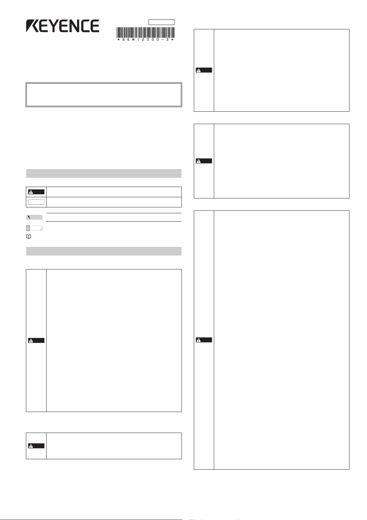
Part Description
Point
DANGER
Transmitter
Beam center-line mark
Receiver Back side
Center Indicators
7-segment display
Function indicators
Beam center-line mark
Setting switch
(2 switches)
Setting switch
(6 switches)
Connector for the
interface unit
(GL-R1UB)
Top
Bottom
End cover
Connector
for the unit
connection
cable
Transmitter Receiver
Switch
No.
Function Configuration
2
Channel
Channel 0
(Not applied)
(Default)
Use Channel for
light interference
prevention when
optical
synchronization
system is applied.
For details, refer to
the "Light
interference
prevention function"
(page 5).
Channel A
1
Channel B
2
Switch
No.
Function Configuration
6
Center
indicator
ON (Green) when all beam axes
are clear (Default)
OFF when all beam axes are clear
(Green OFF)
5
Reduced
resolution
(Safetyrelated
function)
Reduced resolution is not ap plied
(Default).
4
Reduced resolution (one optical
beam) is applied.
3
Reduced resolution (two optical
beams) is applied.
2
Channel
Channel 0
(Not applied)
(Default)
Use Channel for
light interference
prevention when
optical
synchronization
system is applied.
For details, refer to
the "Light
interference
prevention function"
(page 5).
Channel A
1
Channel B
5
43
2
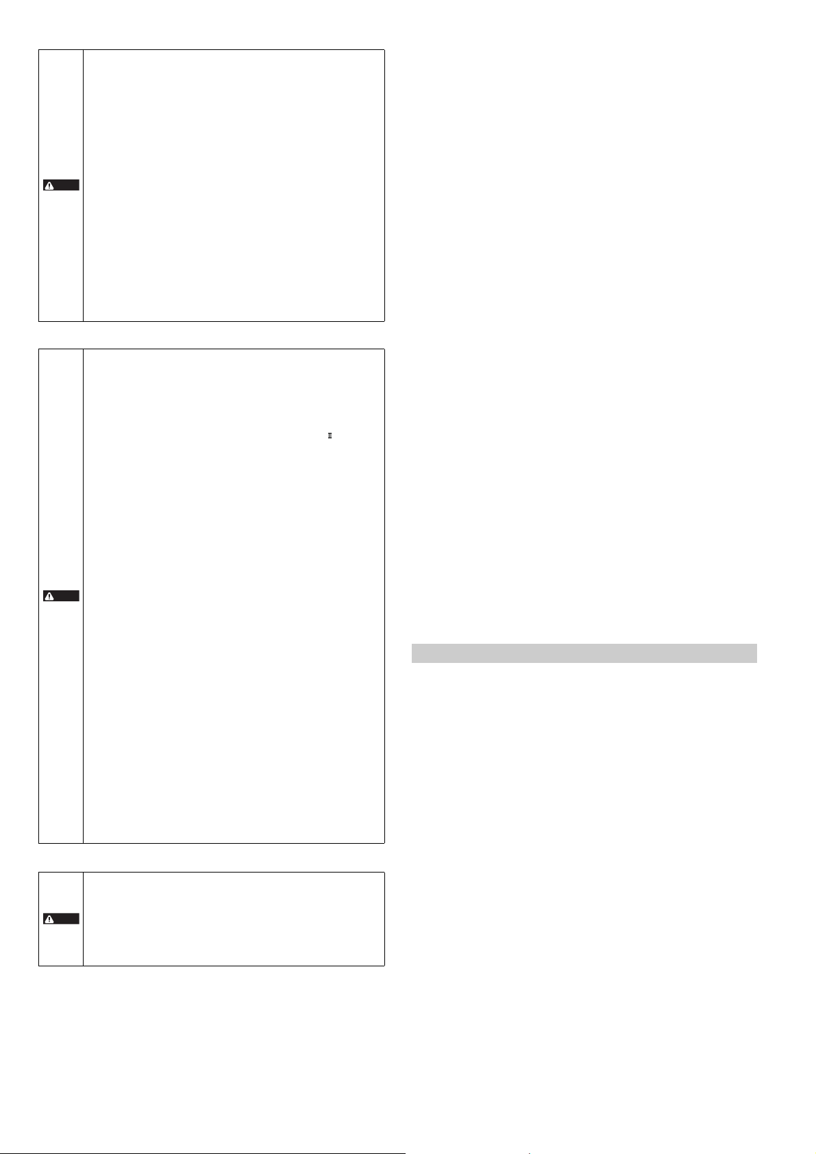
Beam center-line mark
Beam center-line
Specified target detection
capability (position A)
Protection
height
Specified target detection
capability (position B)
Detection
height
a: Beam axis spacing
b: Beam axis diameter
c: Detection capability
a
b
c
Detection zone Protection zone
Specified target detection capability
Detection height Protection height
Operating distance
Beam center-line : An optical path joining the optical center of the emitting element on the transmitter to
Detection height : The height from the top beam center-line to the bottom beam center-line (length).
Protection height : An object approaching the detection zone from the top of the detection height is first
* Refer to the following diagram for an explanation of beam center-line, detection height and protection
height.
the optical center of the corresponding receiving element on the receiver. The GL-R
must be installed so that the beam center-line mark on the transmitter and that on
the receiver face one another and are located at the same height.
detected at point A, which is the distance of the detection capability from the top of
the detection height. The equivalent position on the bottom is called point B. The
height from the top edge of the specified target detection capability that exists at
point A to the bottom edge of the specified target detection capability that exists at
point B is called The "protection height".
The following calculation formula can be defined:
Protection height = "Detection height" + ( 2 x "the specified target detection
capability" ) – "beam axis diameter".
* The side where the end cover has already been installed at shipment is the top side.
Setting switch
2
1
2
1
Detection zone : The zone in which the specified target detection capability can be detected. The
Protection zone : The square area formed with the protection height and the operating distance,
* Refer to the following diagram for detection zone and protection zone.
6
detection zone of the GL-R indicates a square area formed with the detection height
and the operating distance. When an object of the specified target detection
capability is present in this area, the light of the GL-R is blocked, and then the
OSSD goes to OFF state.
which is broader than the detection zone. When an object of the specified target
detection capability is present in this area, the light of the GL-R is blocked, and then
the OSSD goes to OFF state.
Functions and Features
5
43
5
43
2
1
2
1
The functions and features of the GL-R are described in this section.
For more information about these functions, see "GL-R Series User's Manual".
Point
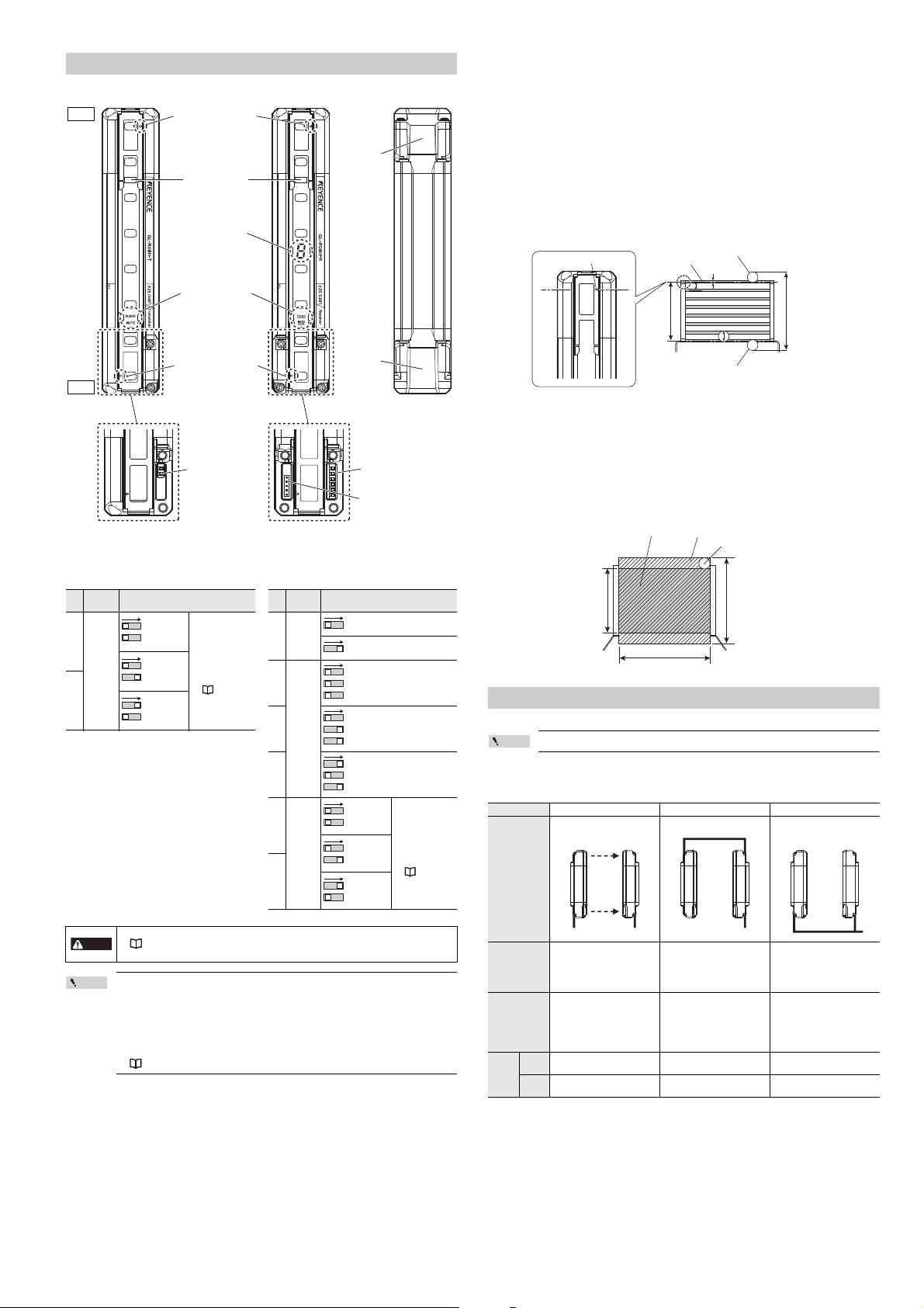
Wiring system
The following three types of wiring systems are available in the GL-R series.
Wiring system Optical synchronization system One-line system Wire synchronization system
Wiring diagram
Transmitter Receiver Transmitter Receiver Transmitter Receiver
• The response time varies according to the configuration of Channel.
"Response time (OSSD)" (page 9)
• The det ection capability varies according to the configuration of reduced res olution.
• The configuration of the setting switch is applied when the power is supplied.
• When th e GL-R is in series connection, the setting switch configuration of the main unit
is applied regardless of the setting switch configuration of the sub unit.
• When th e center indicator and reduced resolution are configured by using the
configuration software, the setting switch must be configured by default. Otherwise an
error occurs.
• When th e GL-R operates in wire synchronization system, the setting switch for Channel
must be configured by default. Otherwise an error occurs.
"Wiring system" (page 3)
• Simplified wiring.
• The unit connection cable is
not needed for the transmitter.
• The input and output functions
on the transmitter are not
available.
• There is a maximum limit for
the total length of cables.
5-core cable
11-core cable
Advantage
Limitation
Applicable
cable
• Wiring is not needed be tween
the transmitter and receiver.
• The Transmitter and the
receiver can operate on
different power supplies.
• The input and output functions
on the transmitter are not
available.
• All indicators other than
"Power" are not available on
the transmitter.
Transmitter
5-core cable Series connection cable
5-core cable
Receiver
11-core cable
3
• All functions of the GL-R are
available.
• Wiring is needed between the
transmitter and the receiver.
7-core cable
11-core cable
7-core cable
11-core cable
E GL-R-IM
Page 4
Wiring system
Optical/wire
synchronization system
One-line
system
Series connection cable
Unit connection cable
Unit connection cable (for extension
use) + Extension cable
* The unit connection cable can not be
connected on the upper part of the GL-R.
Cable for the transmitter 5-core
Cable
combination
Cable for the receiver
OSSD output
AUX (auxiliary) output
Error output
Muting function
Partial muting function
Muting bank function
Muted condition output
Muting lamp output
Override function () ()
Interlock function () () () ()
Available
function
: Available without the configuration software
: Available with the configuration software
() : Available without the configuratio n software, Functionality can be expanded when using the configuration software.
Interlock-reset-ready output
EDM function () () () ()
Wait input
Alert output
Clear/Block output
Reset input (for error)
Reduced resolution function () () () () () () () ()
Fixed blanking function
Channel configuration
(Light interference
prevention function)
Center indicator
configuration
Monitoring function
Optical
synchronization
5-core 11-core 5-core 11-core 7-core 11-core 7-core 11-core
() () () () () () () ()
One-line Wire synchronization
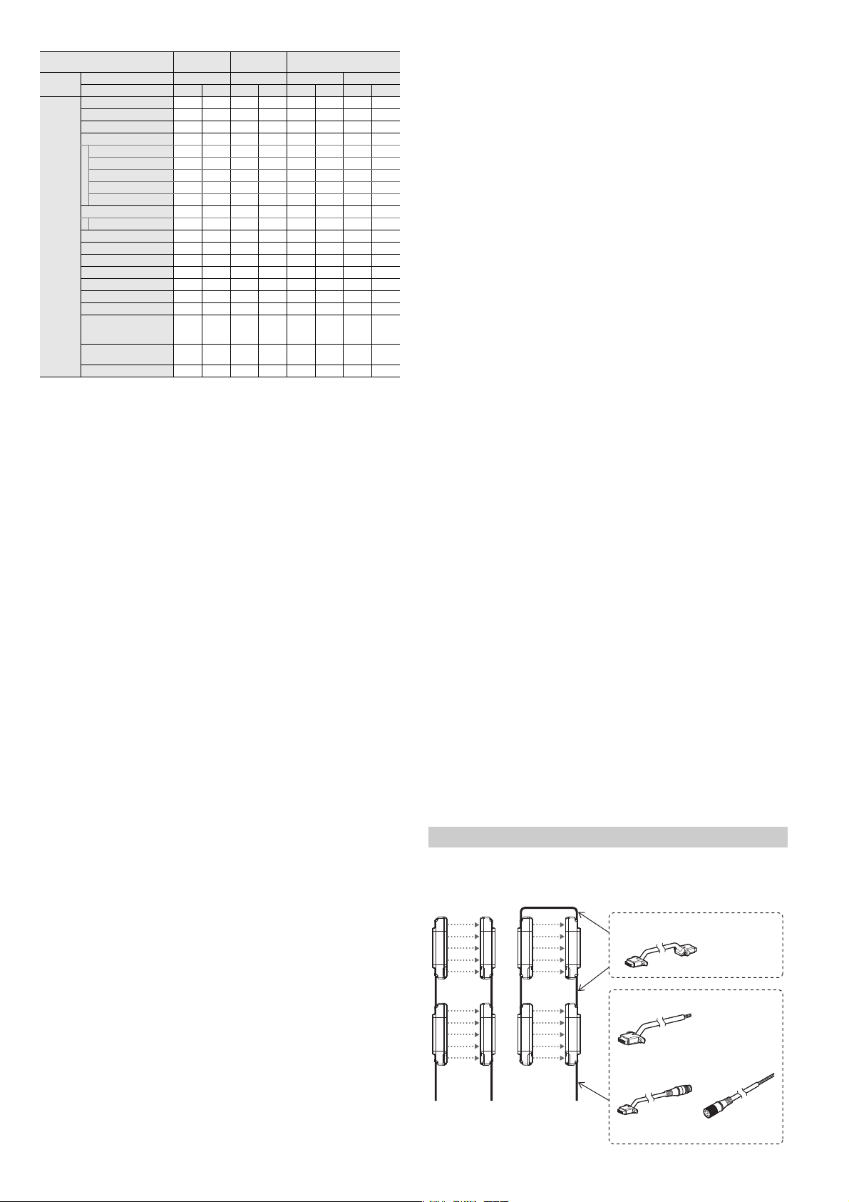
Series connection
7-core 11-core
Series connection
Up to three GL-R units can be serially connected and used as a single light curtain.
OSSD
The OSSD is a safety-related control output. It connects to an external device (load), such as an FSD or
MPCE. The GL-R generates self-diagnosis signals on its internal control circuit to perform diagnostics on
the output circuit (OSSD). These signals periodically force the OSSD into a temporary OFF state when
no interruption exists in the detection zone.
Interlock function
Interlock is a function that prevents the OSSD from automatically going to the ON state from an OFF
state.
You can prevent the unintended start-up and/or the unintended restart of the machine if an interlock is
applied to the GL-R.
External device monitoring (EDM function)
EDM (External Device Monitoring) is a function of the GL-R that monitors the state of the control devices
which are externally connected to the GL-R. The GL-R can detect a fault, such as welded contacts on
external devices, as long as the EDM function is activated.
This function is available only when connecting the 11-core cable to the receiver.
Fixed Blanking
During normal operation, the OSSD remains in the ON state while the GL-R detects no interruption in the
detection zone, and the OSSD goes to the OFF state when the GL-R detects interruption in the detection zone.
On the other hand, if fixed blanking is enabled on certain beam axes, the OSSD remains in the ON state
as long as the GL-R detects interruption on those beam axes and no interruption elsewhere in the
detection zone.
Reduced resolution
During normal operation, the OSSD goes to the OFF state when the GL-R detects interruption in the
detection zone.
On the other hand, if reduced resolution is enabled on the GL-R with the number of beam axes to be
ignored and not monitored specified, the OSSD remains in the ON state even while the GL-R detects
interruption on certain beam axes as long as the total number of interrupted beam axes is less than or
equal to the number of ignored beams.
Muting Function
The muting function is used to temporarily suspend the GL-R's safety functions while the GL-R receives
a signal from muting devices (such as sensors or switches). Before this function can be used, the outputs
from the muting devices must be connected to the muting input terminal on the GL-R.
In addition, the configuration software provides the user with the opportunity to select the beam axes to
be in the muted condition. You can minimize the number of beam axes to be in the muted condition by
using the configuration software. Therefore, you can reduce the risk of interrupting the hazardous zone.
Muting device
When using the muting device, it must be met with the following conditions.
• The muting device output must be N.O. (normally open).
• Output of the muting device must be the output with contacts, and must be PNP output type if PNP
output type cable is used, or NPN output type if NPN output type cable is used. Also, the muting
device must be capable of 2 to 3 mA current.
• Do not use one muting device with multiple outputs in place of two or more muting devices. (Only
one output per one muting device must be used.)
• If the muting device has a timer function that can adjust the output timing, do not use that function.
Muting lamp
When using the muting lamp, it must meet the following conditions.
For an incandescent lamp : rated 24 V DC, 1 to 5.5 W
For an LED indicator : rated current consumption must be 10 to 230 mA.
Conditions for initiation of muting
Muted condition is initiated if all of the following conditions are met:
• Muting input 2 turns ON within 0.04 to 3 seconds after muting input 1 turns ON
• GL-R detects no interruption in the detection zone
• OSSD is in the ON state and remains for 0.5 seconds or more.
E GL-R-IM
Conditions for termination of muting
Muted condition is terminated if one of the following conditions is met:
• Either of the muting inputs goes to the OFF state for at least 5 ms.
• Light curtain goes into the error condition
• Wait input goes to ON state
• The power supply is interrupted or restored.
• Maximum muting period of approx. 5 minutes has been passed.
Changing of conditions for muting
The following muting conditions can be changed through the configuration software or a special
procedures.
Condition for Initiation of muting
1. Time period specification of 0.04 s to 3 s between muting input 1 and muting input 2 can be option.
2. Sequence specification of muting inputs can be option. (Default sequence: muting input 1 is first,
muting input 2 is second.)
Condition for termination of muting
3. Time period specification form muting input OFF to termination of muted condition. (Default is 0
seconds.)
4. Maximum muting period of approx. 5 minutes can be option.
Condition for muting lamp
5. Error condition can be initiated if muting lamp has some failure.
If you choose these options according to your machine application, password setting and/or password
input is required as a special procedure.
The responsible personnel who intends to apply these options mentioned above from 1 to 4 have to
perform the risk assessment based on the machine application.
Muting bank function
The muting bank function can be activated through the configuration software.
You can configure up to three muting banks on the GL-R. Each muting bank is a group of beam axes that
will go into a muted condition upon activation of muting.
In order to activate a muting bank, you must switch (ON and OFF) the muting bank input.
Override function
During normal operation, the OSSD goes to an OFF state if the muting function is deactivated and an
interruption remains in the detection zone of the GL-R. The OSSD OFF state will remain until the
obstruction is removed.
Override function allows a temporary manual suspension of the GL-R safety functions.
This makes it possible to remove the obstruction remaining in the detection zone of the GL-R. (Machine
is able to be manually operated on a temporary basis because the safety function of the GL-R is
temporarily suspended.)
Conditions for initiation of override
Override function is initiated if all of the following conditions are met and the wait input goes to the ON
state within 0.04 s to 1 s after the override input turns ON state.
• GL-R is not in the error condition.
• GL-R detects interruption in the detection zone. (One or more beam axis is blocked.)
• OSSD is OFF state. (including interlock condition)
• Either of muting inputs, or both, turns ON state
Conditions for termination of override
Override function is terminated if one of the following conditions is met:
• All of muting inputs turn OFF.
• Either the override input or wait input, or both, turn OFF.
• Light curtain goes to into the error condition
• Maximum override period of approx. 60 seconds has been passed.
Changing of the condition for override
The following condition can be changed through the configuration software.
Conditions that deactivate the override condition
• Maximum override period of approx. 60 seconds can be option.
If you choose this option according to your machine application, password setting and/or password input
is required. The responsible personnel must securely manage the password. The responsible personnel
who intends to apply this option must perform the risk assessment based on the machine application.
Installation
Overview
4
Page 5

z
z
z
z
Cable installation
• Do not remove the black gasket installed on the connector. Without this gasket the
requirement of IP65 and IP67 cannot be fulfilled.
• Secure ly tighten the cable connector and end cover with the screw in accordance with
DANGER
the torque values specified in this user's manual. Without proper installation, the
requirement of IP65 and IP67 cannot be fulfilled.
• Connect the unit connection cable to the connector port on the lower part of the GL-R.
Removing the end cover on the upper part of the GL-R and connecting the unit
NOTICE
Cable connection to the lower part of the GL-R (The unit connection cable
connection cable may result in GL-R damage.
• The end cover must be connected to the connector except when the series cable is
connected. If both the end cover and series cable are not connected to the connector, an
error occu rs.
and extension cable)
The unit connection cable and extension cable can be used for both the transmitter and
Reference
receiver.
Ensuring proper GL-R installation near a glossy surface
If there is a glossy surface around the GL-R, the GL-R may be affected and may not detect an
interruption in the detection zone.
To avoid this problem, installation must be done according to the following:
Safe
A=2.5°
Approaching direction
A
A
Transmitter
Glossy surface
Area surrounding the
hazardous zone
Transmitter
Object
(Interruption)
A
A
Receiver
Receiver
Dangerous
A=2.5°
Approaching direction
A
A
Transmitter
Glossy surface
Area surrounding the
hazardous zone
Transmitter
Object
(Interruption)
A
A
Receiver
Receiver
M3 cross slot screws (Recommended tightening torque of 0.3 N•m )
Cable connection to the upper part of the GL-R (The series connection
cable)
The series connection cable can be used on both the transmitter and receiver.
Reference
1
M3 cross slot screws
End cover
When the GL-R units are wired by the one-line system, the end cover re moved from the
upper part of the GL-R must be secured to the lower part with the screw. (Recommended
DANGER
tightening torque of 0.3 N•m)
Without the end cover, the requirement of IP65 and IP67 cannot be fulfilled.
Installation of the GL-R unit
Connect all cables to the GL-R before installing the mounting bracket to the GL-R unit.
Point
The installation method differs according to the type of mounting bracket.
For details, see the manual included in the package of mounting bracket or "GL-R Series User's Manual".
Light interference prevention method
Light interference prevention function
• When wire synchronization system is applied
The light interference prevention function automatically reduces mutual interference between GL-R
units.
• When optical synchronization system is applied
The light interference prevention function is applied according to Channel configuration.
The mutual interference is reduced between GL-R units with Channel A and Channel B.
The mutual interference is not reduced between GL-R units with Channel 0 and Channel 0, GL-R
units with Channel 0 and Channel A, or GL-R units with Channel 0 and Channel B.
Channel is configured by using the setting switch at the lower part of front side of GL-R units.
Configure the same Channel to the setting switch on both the transmitter and receiver.
For more information about the setting switch, see also "Part Description" (page 3).
When the GL-R is in series connection, the setting switch configuration of the main unit is
applied regardless of the setting switch configuration of the sub unit.
The response time varies according to the configuration of Channel.
DANGER
"Wiring system" (page 3)
Series connection
Connecting GL-R in series can prevent mutual interference.
"Response time (OSSD)" (page 9)
2
M3 cross slot screws
(Recommended tightening torque of 0.3 N•m)
Object (Interruption)
AA
Glossy surface
Area surrounding the
hazardous zone
When determining a specific installation distance, refer to the following values including the installation
tolerance.
X
Transmitter
Glossy surface
Operating distance "X" Minimum installation distance "Y"
Less than 3 m 0.13 m
3 m or more X/2 x tan5° = 0.0437 X
Receiver
Y
Object (Interruption)
AA
Glossy surface
Area surrounding the
hazardous zone
X
Transmitter Receiver
5°
Y
Glossy surface
Wiring
• Each model is connected to one cable. Therefore, at least two cables are needed as a
Point
system, one for the transmitter and another for the receiver.
• All cables can be use d for both the transmitter and receiver.
• The combination of the wiring sy stem and cable determines the functions that can be
used. Different types of Cables can be used for the transmitter and receive r.
"Wiring system" (page 3)
• Be sure to match the numbers of conductors (core wires) when using the unit connection
cable for extension use and the extension cable.
Cable specification
(1) Cable length
1. Optical synchronization system, wire synchronization system
The sum of the length for the unit connection cable and extension cable must be 30 m or less.
This limitation applies separately to the entire transmitter cable setup and the entire receiver
cable setup.
2. One-line system
The sum of the length for all of the unit connection cables, extension cables and series cables
must be 30 m or less.
• Cables must be within the lengths specified. Failure to follow this specification may
cause improper operation of safety functions, and may create a dangerous situation.
• The ser ies connection cable cannot be cut or extended. If the cable is cut or extended,
DANGER
safety features may not operate properly. Do not allow this to happen as it is extremely
dangerous.
(2) Minimum cable bending radius : 5 mm
(3) Identification of connector cables
Connector
Connector colors
PNP output type cables or series connection cables : Black connectors
NPN output type cables : Grey connectors
PNP output type cables and NPN output type cables cannot be used at the same time
Point
(mixed wiring is not possible). One type of cable must be chosen based on the application.
5
E GL-R-IM
Page 6

Cable color and pin position
Output circuit (PNP type cable) Output circuit (NPN type cable)
Main
circuit
+24 V
Black or White
0 V
+24 V
Black or White
0 V
Main
circuit
Blue
Brown
Blue
Brown
External device
External device
Input circuit (PNP type cable)
+24 V
0 V
(Input line)
(Input line)
+24 V
0 V
Blue
Brown
Blue
Brown
Input circuit (NPN type cable)
Main
circuit
Main
circuit
NOTICE
Transmitter
(FE) Grey
(0V) Blue
(Not in use) White
(Not in use) Black
(+24V) Brown
(+24V) Brown
(OSSD1) Black
(OSSD2) White
(0V) Blue
(FE) Grey
Receiver
(FE) Grey
(0V) Blue
(Not in use) White
(Not in use) Black
(+24V) Brown
(+24V) Brown
(OSSD1) Black
(OSSD2) White
((0V) Blue
(FE) Grey
Transmitter
Receiver
(+24V) Brown
(OSSD1) Black
(OSSD2) White
(0V) Blue
(FE) Grey
(AUX output) Red
(EDM input) Red/Black
(Reset input) Yellow
(Interlock mode selection input) Pink
(FE) Grey
(0V) Blue
(Not in use) White
(Not in use) Black
(+24V) Brown
Orange (Not in use)
K1
K2
S1
K3
K1 K2
Orange/Black (Not in use)
Transmitter
Receiver
(+24V) Brown
(OSSD1) Black
(OSSD2) White
(0V) Blue
(FE) Grey
(AUX output) Red
(EDM input) Red/Black
(Reset input) Yellow
(Interlock mode selection input) Pink
(FE) Grey
(0V) Blue
(Not in use) White
(Not in use) Black
(+24V) Brown
K3
K1 K2
Orange (Not in use)
Orange/Black (Not in use)
K1
K2
S1
Transmitter
Receiver
• When the synchronization wire 1 is wired between the transmitter and rec eiver, and the
Reference
5-core cable
7-core cable
11-core cable
synchronization wire 2 is wired in the same manner, the GL-R operates in wire synchronization
system.
• When the synchronization wire 1 or 2 is not connected, the GL-R operates in optical
synchronization system.
• When optical synchronization system or one-line system is applied, the input and output
functions on the transmitter are not available.
• The func tions assigned to the input and output may differ according to the configuration when
setting through the configuration software.
"Wiring system" (page 3)
Pin No Wire Color
Transmitter Receiver
Assigned function
1 Brown +24 V +24 V
2 White (Not in use) OSSD2
3Blue 0 V 0 V
4 Black (Not in use) OSSD1
5Grey FE FE
M12 connector male pin assignment M12 connector female pin assignment
Reference
2
1
5
3
4
Pin No Wire Color
Transmitter Receiver
Assigned function
1 White Wait input OSSD2
2 – (Not in use) (Not in use)
3 Black Error output OSSD1
4 Brown +24 V +24 V
5 Orange Synchronization 1 (RS485_+) Synchronization 1 (RS485_+)
6 Orange/Black Synchronization 2 (RS485_–) Synchronization 2 (RS485_–)
7Blue 0 V 0 V
8Grey FE FE
M12 connector male pin assignment M12 connector female pin assignment
Reference
2
1
83 7
4
6
5
Pin No Wire Color
Transmitter Receiver
Assigned function
1 White Wait input OSSD2
2 – (Not in use) (Not in use)
3 Black Error output OSSD1
4 Yellow Override input RESET input
5 Orange Synchronization 1 (RS485_+) Synchronization 1 (RS485_+)
6 Orange/Black Synchronization 2 (RS485_–) Synchronization 2 (RS485_–)
7Blue 0 V 0 V
8 Red Muting lamp output AUX (auxiliary) output
9 Red/Black Muting input 2 EDM input
10 Brown +24 V +24 V
11 Pink Muting input 1 Interlock selection input
12 Grey FE FE
Examples of Wiring
The functions assigned to the input and output may differ according to the configuration
when configuring through the configuration software.
For more information, see the "GL-R Series user's Manual".
Symbols
R1, R2 : External device (Safety PLC, Safety relay unit, etc)
K1, K2 : External device (Force guided relay, magnet contactor, etc)
K3 : Solid state contactor
S1 : Switch used for reset input
S2 : Switch used for wait input
S3 : Switch used for override input
S4, S5, S6 : Switch used for muting bank inputs
L1 : Muting lamp (Incandescent lamp or LED lamp)
P1, P2 : Muting device (Self-contained photoelectric sensors, etc.)
M : 3-phase motor
PLC : For NON SAFETY-RELATED system control use
*1 These are NON SAFETY-RELATED components.
Optical synchronization system
1
2
5
4
3
1
2
87 3
6
4
5
Transmitter: 5-core cable, Receiver: 5-core cable
(1) PNP output cable
(2) NPN output cable
Transmitter: 5-core cable, Receiver: 11-core cable
When using the EDM function and interlock function
(1) PNP output cable
*1
*1
*1
R1 R2
R1 R2
M14 connector male pin assignment M14 connector female pin assignment
Reference
12
10
3
9
12 11
4
8
5
7
6
I/O circuit diagram
Reference
E GL-R-IM
• Grey wire (FE) is electrically-connected to the light cur tain body case.
•
The light curtai n body case and internal power signal lines are couple d by capacitor (3 kV, 100 pF).
21
10
9
3
11 12
8
7
5
6
4
M
K2K1
OUT IN
PLC
(2) NPN output cable
K2K1
OUT IN
M
PLC
6
Page 7

z
z
z
z
z
One-line system
• The series connection cable must be used to connect the transmitter and receiver.
• The unit connection cable is not needed for the transmitter.
• The wiring for the receiver is the same as optical synchronization system.
Transmitter: Series connection cable, Receiver: 5-core cable
(1) PNP output cable
Transmitter
Receiver
(0V) Blue
(OSSD1) Black
R1 R2
(FE) Grey
(OSSD2) White
(+24V) Brown
(2) NPN output cable
Transmitter
Wire synchronization system
Transmitter: 7-core cable, Receiver: 7-core cable
Receiver
(0V) Blue
(OSSD1) Black
R1 R2
(FE) Grey
(OSSD2) White
(+24V) Brown
(1) PNP output cable
Transmitter
Orange (Synchronization 1)
Orange/Black (Synchronization 2)
(0V) Blue
(FE) Grey
(+24V) Brown
(Wait input) White
(Error output) Black
S2
Receiver
(0V) Blue
(OSSD1) Black
R1 R2
(FE) Grey
(OSSD2) White
(+24V) Brown
Indicators
Transmitter
7-segment display
Function indicator
Function indicators
Name Indicator Description
POWER
(Orange)
MUTE
(Orange)
* When optical synchronization system is
applied, only the "POWER" indicator turns ON
on the transmitter.
"Wiring system" (page 3)
7-segment display
Upon power-up
Wire synchronization
During normal operation
Applying the reduced resolution function or fixed blanking function.
Wait input is activated.
Transmitter
Light ON Power ON (Transmitter)
Light OFF Power OFF (Transmitter)
Muted condition or
Light ON
Override condition
Blinking
Muting input 1 ON
slowly
Muting input 2 ON or
Blinking
Muting input 1 ON and
Muting input 2 ON
Muting input 1 OFF and
Light OFF
Muting input 2 OFF
Channel 0 Channel A Channel B
Condition Display
Muting input 1 is activated.
Optical synchronization
Receiver
Name Indicator Description
OSSD
(Red/
Green)
INTERLOCK
(Yellow)
Receiver
Light in
OSSD OFF
red
Light in
OSSD ON
green
Amount of received light is
Blinking in
unstable.
green
(Alert output OFF)
Light OFF Power OFF (Receiver)
Light ON Interlock condition
Interlock reset ready condition
Blinking
(Interlock reset ready output ON)
Light OFF No interlock or error co ndition
PLC
(2) NPN output cable
Transmitter
Orange/Black (Synchronization 2)
(0V) Blue
(FE) Grey
(Wait input) White
(Error output) Black
S2
PLC
Orange (Synchronization 1)
(+24V) Brown
Muting input 2 is activated.
Muting input 1 and 2 are both
Receiver
Applying the muting
function or override
function.
(0V) Blue
(OSSD1) Black
R1 R2
(FE) Grey
(OSSD2) White
Other than those above. Turn OFF
*1 When not in the muted condition because conditions for initiation of muting are not met.
*2 When not in the override condition because conditions for initiation of override are not met.
Error condition
When an error occurs, the OSSD goes to the OFF-state and the GL-R goes to the error condition.
For the 7-segment display in the error condition, refer to "Troubleshooting" (page 10).
(+24V) Brown
*1
activated
.
Muted condition
Override input is activated
Override condition.
*2
.
7
E GL-R-IM
Page 8

Center indicator
GL-RH
Beam axis
Center
indicator
(Upper)
Center
indicator
(Middle)
Center
indicator
(Lower)
Dimensions
Center indicator (Upper) : indicates whether interruption is present in the top
Center indicator (Middle) :
Center indicator (Lower) : indicates whether interruption is present in the bottom
Center
Light OFF red light green light
indicator
Top beam axis
Upper
is blocked
Top beam axis
or Bottom
beam axis is
blocked
Bottom beam
Lower
axis is blocked
* The center indicator on the transmitter is OFF when optical synchronization
system is applied.
beam axis or not. (clear or blocked)
indicates whether the middle axis beams are
interrupted or not.
beam axis or not. (clear or blocked)
Although the top beam axis is
unblocked, the others are
blocked
Although the top and bot tom
beam axis are unblocked, the
middle beams are blocked
Although the bottom bea m
axis is unblocked, the others
are blocked
No interruption is
present in
detection zone of
the GL-R. (clear)
Blinking red
light
Error conditionMiddle
Units: mm
Transmitter and Receiver
38
32
F
E10
B
A
C
GL-RH
Units: mm
Model
Beam axes
GL-R08H 8 160 140 185
GL-R12H 12 240 220 265 120
GL-R16H 16 320 300 345 160
GL-R20H 20 400 380 425 200
GL-R24H 24 480 460 505 240
GL-R28H 28 560 540 585 280
GL-R32H 32 640 620 665 320
GL-R36H 36 720 700 745 360
GL-R40H 40 800 780 825 400
GL-R44H 44 880 860 905 440
GL-R48H 48 960 940 985 480
GL-R52H 52 1040 1020 1065 520
GL-R56H 56 1120 1100 1145 560
GL-R60H 60 1200 1180 1225 600
GL-R64H 64 1280 1260 1305 640
GL-R72H 72 1440 1420 1465 720
GL-R80H 80 1600 1580 1625 800
GL-R88H 88 1760 1740 1785 880
GL-R96H 96 1920 1900 1945 960
GL-RL
A: Length
B: Detection height C: Protection height D: Beam axis pitch
20 10 22.5
E F G
Units: mm
Model
Beam axes
GL-R04L 4 160 120 205
GL-R06L 6 240 200 285 120
GL-R08L 8 320 280 365 160
GL-R10L 10 400 360 445 200
GL-R12L 12 480 440 525 240
GL-R14L 14 560 520 605 280
GL-R16L 16 640 600 685 320
GL-R18L 18 720 680 765 360
GL-R20L 20 800 760 845 400
GL-R22L 22 880 840 925 440
GL-R24L 24 960 920 1005 480
GL-R26L 26 1040 1000 1085 520
GL-R28L 28 1120 1080 1165 560
GL-R30L 30 1200 1160 1245 600
GL-R32L 32 1280 1240 1325 640
A: Length
B: Detection height C: Protection height D: Beam axis pitch
40 30 42.5
E F G
80
80
G
D
32.9
Setting switchesInterface unit connector
Antivibration bracket for the Adjustable angle
mounting bracket
Antivibration bracket for the straight mounting
bracket
(only receiver)
If the length for a single GL-R unit is 1280 mm or greater, use the following antivibration
mounting bracket additionally as an intermediate support bracket. The antivibration
mounting bracket must be selected according to the mounting bracket and installed on the
center of the GL-R unit indicated as position "G".
NOTICE
Adjustable angle mounting bracket
No dead zone mounting bracket
Straight mounting bracket
L-shaped mounting bracket L-shaped mounting bracket
Mounting bracket Antivibration bracket
GL-RF
Units: mm
Model
Beam axes
GL-R23F 23 240 220 244
A: Length
GL-R31F 31 320 300 324 160
GL-R39F 39 400 380 404 200
GL-R47F 47 480 460 484 240
GL-R55F 55 560 540 564 280
GL-R63F 63 640 620 644 320
GL-R71F 71 720 700 724 360
GL-R79F 79 800 780 804 400
GL-R87F 87 880 860 884 440
GL-R95F 95 960 940 964 480
GL-R103F 103 1040 1020 1044 520
GL-R111F 111 1120 1100 1124 560
GL-R119F 119 1200 1180 1204 600
GL-R127F 127 1280 1260 1284 640
B: Detection height C: Protection height D: Beam axis pitch
10 10 12
E F G
120
E GL-R-IM
8
Page 9

Specifications
Specifications
Beam axis spacing/Lens diameter 10 mm/4 20 mm/5 40 mm/5
Detection capability 14 mm 25 mm 45 mm
Operating distance 0.2 to 10 m
Effective aperture angle Max. ±2.5° (When operating distance is 3 m (9.84 ft.) or more)
Light source Infrared LED (870 nm)
Response time
OSSD operation Turns on when no interruptions are present in the detection zone
Synchronization between the transmitter
and receiver
Light interference prevention function
Control output
(OSSD)
Supplemental
output
(Non-safetyrelated output)
Input
Power suppl y
Protection circuit
Environmental
resistance
Material
Weight see "Weight" (page 10)
Approved
standard
Parameter for
IEC61508
*1 When the option front protection cover is installed on the one of transmitter or receiver, the Operating
*2 When the GL-R is used under surrounding air temperatures between 50 to 55°C, the Maximum load
*3 For PFHd of each GL-R, contact your nearest KEYENCE office.
Model GL-RF GL-RH GL-RL
*1
Optical synchronizati on (Channel 0) or Wire synchronization: 6.6 to 18.1 ms
Optical synchronization (Channel A or B): 6.9 to 27.4 ms
Optical synchronizat ion or Wire synchronization
Prevents mutual interference in up to two GL-R systems.
Optical synchronization: prevented by Channel A and B with setting switch
Output
Max. load current 500 mA
Residual voltage (during
ON)
OFF state voltage Max. 2.0 V (with a cable length of 5 m (16.4 ft.))
Leakage current Max. 200 A
Max. capacitive load 2.2 F
Load wiring resistance Max. 2.5
AUX Transistor outputs. (Compatible with bo th PNP and NPN)
Error output
Muting lamp output
EDM input
Wait input
Reset input
Muting input 1, 2
Override input
Power voltage DC24 V ± 20% (Ripple P-P 10% or less, Class2)
Current consumption Transmitter: 37 to 81 mA, Receiver: 66 to 91 mA
Enclosure rating IP65 / IP67 (IEC60529)
Overvoltage category
Ambient temperature -10 to +55°C (No freezing)
Storage ambient
temperature
Relative humidity 15% to 85%RH (No condensation)
Storage relative humidity 15% to 95%RH
Ambient light White incandescent lamp: 3,000 lx or less, Sunlight: 20,000 lx or less
Vibration
Shock
Main unit case Aluminum
Upper case/Lower case Nylon (GF30%)
Front cover Polycarbonate, SUS304
EMS IEC61496-1, EN61496-1, UL61496-1
EMC
EMI EN55011 ClassA, FCC Part15B ClassA, ICES-003 ClassA
Safety
T1 (Proof test interval) 20 years
PFHd (average frequency
of a dangerous failure per
hour)
Hardware fault toleranc e 1
Type of element Type B
Failure response time Within a response time
Safe state OSSDs are in OFF-state
distance is shorten by 0.5 m. When the front covers are installed on both of the transmitter and
receiver, the Operating distance is shorten by 1.0 m.
Load current: Max. 50 mA, Residual voltage: Max. 2.5 V
LED lamp (load current :10 to 230 mA) can be connected
< with PNP cable >
ON-voltage: 10 to 30 V
OFF-voltage: Open or 0 to 3 V
Short-circuit current:
Approx. 2.5 mA
(Approx. 10 mA for EDM)
Reverse current protection, sho rt-circuit protection for each outpu t, surge protection for each output
10 to 55 Hz, 0.7 mm compound amplitude, 20 sweeps each in X, Y and Z directions
100 m/s2 (Approx. 10 G) 16 ms pulse in X, Y and Z directions 1,000 times each axis
IEC61508, EN61508 (SIL3), IEC62061, EN62061 (SIL CL3)
(Determined by wiri ng)
Wire synchronization: prevented automatically
2 transistor outputs.
(PNP or NPN is determined by the cable type)
Max. 2.5 V (with a cable length of 5 m (16.4 ft.))
(with a cable length of 5 m (16.4 ft.))
Incandescent lamp (24 VDC, 1 to 5.5 W) or
-25 to +60°C (No freezing)
IEC61496-1, EN61496-1, UL61496-1 (Type 4 ESPE)
IEC61496-2, EN61496-2, UL61496-2 (Type 4 AOPD)
EN ISO13849-1:2008 (Category 4, PL e)
1.78×10
UL508
UL1998
-9
to 5.14×10
*2
*1
0.2 to 15 m
< with NPN cable >
ON-voltage: 0 to 3 V
OFF-voltage: Open or
10 V to Power voltage
Short-circuit current:
Approx. 2.5 mA
(Approx. 10 mA for EDM)
-9
current should not exceed 350 mA.
Response time (OSSD)
GL-RF
Model
GL-R23F 6.9 49.2 64.4 9.3 5 2.7 74.0
GL-R31F 7.8 50.5 67.9 10.7 54.8 79.5
GL-R39F 8.6 51.8 71.3 12.1 56.9 85.1
GL-R47F 9.5 53.1 74.8 13.5 59.0 90.7
GL-R55F 10.4 54 .3 78.3 14.9 61.1 96.3
GL-R63F 11.2 55.6 81.7 16.3 63.2 101.8
GL-R71F 12.1 56.9 85.2 17.6 65.3 107.4
GL-R79F 13.0 58.2 88.6 19.0 67.4 113.0
GL-R87F 13.8 59.5 92.1 20.4 69.4 118.5
GL-R95F 14.7 60.8 95.5 21.8 71.5 124.1
GL-R103F 15.5 62.1 99.0 23.2 73.6 129.7
GL-R111F 16.4 63.4 102.4 24.6 75.7 135.2
GL-R119F 17.3 64.7 105.9 26.0 77.8 140.8
GL-R127F 18.1 66.0 109.4 27.4 79.9 146.4
Wire synchronization, One-line or
Optical synchronization system (Channel 0)
ONOFF OFFON *1All blockedON *2ONOFF OFFON *1All blockedON
Response time (OSSD)
Optical synchronization system
(Channel A or B)
GL-RH
Model
GL-R08H 6.6 48.7 63.1 6.9 49.1 64.2
GL-R12H 6.6 48.7 63.1 7.4 49.9 66.3
GL-R16H 6.6 48.7 63.1 8.1 50.9 69.1
GL-R20H 6.6 48.7 63.1 8.8 52.0 71.9
GL-R24H 7.0 49.3 64.9 9.5 53.0 74.7
GL-R28H 7.4 50.0 66.6 10.2 54.0 77.5
GL-R32H 7.9 50.6 68.3 10.9 55.1 80.2
GL-R36H 8.3 51.3 70.0 11.6 56.1 83.0
GL-R40H 8.7 51.9 71.8 12.3 57.2 85.8
GL-R44H 9.2 52.6 73.5 12.9 58.2 88.6
GL-R48H 9.6 53.2 75.2 13.6 59.3 91.4
GL-R52H 10.0 53.9 77.0 14.3 60.3 94 .2
GL-R56H 10.5 54.5 78.7 15.0 61.4 96 .9
GL-R60H 10.9 55.2 80.4 15.7 62.4 99 .7
GL-R64H 11.3 55.8 82.1 16.4 63.4 102.5
GL-R72H 12.2 57.1 85.6 17.8 65.5 108.1
GL-R80H 13.1 58.4 89.1 19.2 67.6 113.7
GL-R88H 13.9 59.7 92.5 20.6 69.7 119.2
GL-R96H 14.8 61.0 96.0 22.0 71.8 124.8
Wire synchronization, One-line or
Optical synchronization system (Channel 0)
ONOFF OFFON *1All blockedON *2ONOFF OFFON *1All blockedON
Response time (OSSD)
Optical synchronization system
(Channel A or B)
GL-RL
Model
GL-R04L 6.6 48 .7 63.1 6. 9 49. 1 64.2
GL-R06L 6.6 48 .7 63.1 6. 9 49. 1 64.2
GL-R08L 6.6 48 .7 63.1 6. 9 49. 1 64.2
GL-R10L 6.6 48 .7 63.1 7. 0 49. 3 64.9
GL-R12L 6.6 48 .7 63.1 7. 4 49. 9 66.3
GL-R14L 6.6 48 .7 63.1 7. 7 50. 4 67.7
GL-R16L 6.6 48 .7 63.1 8. 1 50. 9 69.1
GL-R18L 6.6 48 .7 63.1 8. 4 51. 4 70.5
GL-R20L 6.6 48 .7 63.1 8. 8 52. 0 71.9
GL-R22L 6.8 49 .0 64.0 9. 1 52. 5 73.3
GL-R24L 7.0 49 .3 64.9 9. 5 53. 0 74.7
GL-R26L 7.2 49 .6 65.7 9. 8 53. 5 76.1
GL-R28L 7.4 50.0 66.6 10.2 54.0 77.5
GL-R30L 7.7 50.3 67.5 10.5 54.6 78.9
GL-R32L 7.9 50.6 68.3 10.9 55.1 80.2
*1 If the interruption is present in the detection zone for less than 80 ms, the response time (OFF to
ON) will be 80 ms or more to ensure that the OSSD maintains the OFF state for more than 80 ms.
*2 "All blocked" means the situation where the GL-R operates in optical synchronization system and
the transmitter and receiver is not synchronized (top and bottom beam axes are both blocked). In
this situation, the response time is longer because the GL-R synchronizes the transmitter and
receiver first and then determines the clear or blocked.
Point
Wire synchronization, One-line or
Optical synchronization system (Channel 0)
ONOFF OFFON *1All blockedON *2ONOFF OFFON *1All blockedON
• When the GL-R units are connected in series, the response ti me is calculated
according to the following steps;
1. Sum up the response time of all unit.
2. Subtract the following time from the result of previous step.
ON to OFF
One sub unit: 2 ms
Two sub unit: 4.2 ms
(When Optical synchronization system and Channel A or B)
One sub unit : 2.7 ms
Two sub unit: 5.7 ms
OFF to ON
One sub unit: 42 ms
Two sub unit: 84 ms
When connecting the GL-R32H (32 beam axes), GL-R24H (24 beam axes) , and GLR12L (12 beam axes) in series for one-line system, the response time of each unit is
7.9 ms, 7.0 ms, and 6.6 ms respectively, and the response time (ON to OFF) is 7.9 ms +
7.0 ms + 6.6 ms - 4.2 ms = 17.3 ms.
the response time (OFF to ON) is 50.6 ms + 49.3 ms + 48.7 ms - 84 ms = 64.6 ms.
• 2.0 m/s is the maximum object detection speed of the GL-R series.
Response time (OSSD)
Optical synchronization system
(Channel A or B)
Units: ms
Units: ms
Units: ms
*2
*2
*2
9
E GL-R-IM
Page 10

Current consumption
Units: mA Units: mA Units: mA
Model
Current
consumption (Max.)
Transmitter
Receiver
GL-R23F 50 70
GL-R31F 54 71
GL-R39F 57 72
GL-R47F 60 74
GL-R55F 62 75
GL-R63F 64 77
GL-R71F 66 78
GL-R79F 67 80
GL-R87F 69 81
GL-R95F 71 83
GL-R103F 72 84
GL-R111F 74 85
GL-R119F 76 87
GL-R127F 78 89
Model
Current
consumption (Max.)
Transmitter
Receiver
GL-R08H 43 66
GL-R12H 46 68
GL-R16H 50 69
GL-R20H 53 71
GL-R24H 57 72
GL-R28H 59 73
GL-R32H 61 74
GL-R36H 63 75
GL-R40H 65 76
GL-R44H 66 77
GL-R48H 68 79
GL-R52H 69 80
GL-R56H 71 81
GL-R60H 72 82
GL-R64H 73 83
GL-R72H 75 85
GL-R80H 77 87
GL-R88H 79 89
GL-R96H 81 91
Model
Current
consumption (Max.)
Transmitter
Receiver
GL-R04L 37 66
GL-R06L 39 67
GL-R08L 41 68
GL-R10L 43 69
GL-R12L 46 70
GL-R14L 48 71
GL-R16L 50 72
GL-R18L 52 73
GL-R20L 54 75
GL-R22L 56 75
GL-R24L 57 76
GL-R26L 59 77
GL-R28L 60 78
GL-R30L 61 79
GL-R32L 62 80
Units: g Units: g Units: g
Model
Weight
Transmitter
Receiver
GL-R23F 320 330
GL-R31F 430 440
GL-R39F 550 550
GL-R47F 660 670
GL-R55F 780 780
GL-R63F 890 900
GL-R71F 1000 1010
GL-R79F 1200 1200
GL-R87F 1300 1300
GL-R95F 1400 1400
GL-R103F 1500 1500
GL-R111F 1600 1600
GL-R119F 1700 1700
GL-R127F 1800 1900
Model
Weight
Transmitter
Receiver
GL-R08H 210 210
GL-R12H 320 330
GL-R16H 430 440
GL-R20H 550 550
GL-R24H 660 660
GL-R28H 770 770
GL-R32H 880 890
GL-R36H 1000 1000
GL-R40H 1110 1110
GL-R44H 1220 1220
GL-R48H 1330 1340
GL-R52H 1440 1450
GL-R56H 1560 1560
GL-R60H 1670 1680
GL-R64H 1780 1790
GL-R72H 2010 2010
GL-R80H 2230 2240
GL-R88H 2450 2460
GL-R96H 2680 2690
Model
Weight
Transmitter
Receiver
GL-R04L 210 210
GL-R06L 320 330
GL-R08L 430 440
GL-R10L 550 550
GL-R12L 660 660
GL-R14L 770 770
GL-R16L 880 890
GL-R18L 1000 1000
GL-R20L 1110 1110
GL-R22L 1220 1220
GL-R24L 1330 1340
GL-R26L 1440 1450
GL-R28L 1560 1560
GL-R30L 1670 1680
GL-R32L 1780 1790
*1 The above current consumption does not include the current consumed via OSSD output.
*2 If inputs other than EDM input turn on, consumption current per input increases by 2.5 mA.
Weight
Troubleshooting
If the GL-R is not functioning normally, check the GL-R indicators first.
The GL-R is in an error condition under the following situations.
• The center indicators blink in red.
• The 7-segment display indicates "".
If the GL-R does not demonstrate the above situations, the GL-R is not in an error condition.
If the GL-R is in an error condition
Indication Error name Cause Check and corrective action
E GL-R-IM
Wiring error
The end cover on the
receiver is not connected.
The unit connection cable
is connected to the upper
part of the GL-R.
Transmitter and receiver
are not the same model.
When the GL-R operates in wire synchronization system
The synchronization wire is
not wired correctly or
disconnected.
When the GL-R operates in one-line system
The unit connection cable
is connected to the
transmitter.
The series connection
cable is connected to the
lower part of the GL-R.
When the GL-R is in series connection.
The sub unit is not
connected correctly.
The sub unit is broken.
When the error is cleared by restarting the GL-R.
The synchronization wire is
affected by external noise.
Check that the end cover is installed on the receiver
correctly.
"Cable installation" (page 5)
Connect the unit connection cable to the lower part of
the GL-R.
"Cable installation" (page 5)
Check that all transmitter and receiver models are
paired correctly.
Check the wiring of the synchronization wire.
"Cable color and pin position" (page 6)
• Connect the unit connection cable to the receiver.
• Do not connect the unit connection cable to the
transmitter.
"Cable installation" (page 5)
Connect the series connection cable to the upper part
of the transmitter and receiver.
"Cable installation" (page 5)
• Check for the direction of the sub unit installation.
• Check whether the receiver o f sub unit is connected
to the transmitter of main unit.
• Check whether the total numbe r of beam axes is
more than 240.
"Series connection" ( page 4)
Check that the sub unit operates correctly when not in
series connection.
Check for noise source (inverter, servomotor, etc.)
around the GL-R installatio n location and cables.
Indication Error name Cause Check and corrective action
Setting switch error
Configuration error
Interlock error
EDM error
Receiver error
Transmitter error
OSSD1 error
OSSD2 error
Sub unit error
Communication error
Muting lamp
disconnection error
Muting lamp over
current error
Synchronization beam
axis error
System error
:
*1 All indicators on the transmitter may turn OFF.
*2 This error occurs only when the muting lamp error is configured to cause error condition by using the
configuration software.
The configuration of the
setting switch is out of
specification.
The setting switch is
configured to something
other than Channel 0 in
wire synchronization
system.
The configuration of the
setting switch overlaps the
configuration uploaded
from the configuration
software.
The unit configuration is
different from the
configuration uploaded
from the software.
The upload of configuration
has not been completed
correctly when using the
configuration software.
Interlock mode selection
input or reset input are
wired incorrectly.
EDM input is not
connected correctly.
There is a welded contact
on the external device.
The receiver is affected by
ambient light.
The transmitter is broken. Replace the transmitter.
When the error is cleared by restarting the GL-R.
The transmitter is affected
by external noise.
When the error is cleared by restarting the GL-R.
OSSD is affected by
external noise.
There is a voltage surge
affecting the OSSD due to
an inductive load.
The power supply voltage
has fallen continuously or
experienced a sudden
drop.
When the error is not cleared by restarting the GL-R.
• OSSD is short-circuited
to 0 V or 24 V of power
supply.
• OSSDs are shortcircuited to each other.
• OSSD is short-circuited
to other wires.
Too much current is
flowing through the OSSD.
OSSD is broken. Replace the receiver.
The sub unit is broken. Replace th e sub unit.
When the error is cleared by restarting the GL-R.
The sub unit or series
cable is affected by
external noise.
When the error is cleared by restarting the GL-R.
The synchronization wire is
not wired correctly or is
disconnected.
The synchronization lines
in the cable are affected by
external noise.
The power supply voltage
*1
has fallen continuously or
experienced a sudden
drop.
When the error is not cleared by restarting the GL-R.
The synchronization wire is
not connected correctly or
is disconnected.
The connection with the
GL-R in series is broken.
The muting lamp is not
connected correctly.
*2
The muting lamp is broken. Replace the muting lamp.
The muting lamp is not
connected correctly.
Too much power is
*2
consumed by the muting
lamp.
The muting lamp is broken. Replace the muting lamp.
When the GL-R operates in
optical synchronization
system, the fixed blanking
or muting function is
applied to both the uppe r
and lower beam axes (for
synchronization control).
The power supply voltage
has fallen continuously or
experienced a sudden
drop.
The GL-R is broken. Replace the GL-R.
Check the configuration of the set ting switch.
"Setting switch" (page 3)
Modify the configuration of the setting switch or modify
the configuration by the configuration sof tware.
"Setting switch" (page 3)
Check the model name of main uni t and sub unit and
whether the unit configuration from the software is
identical to the actual unit configuration.
Upload the configuration again.
Rewire the interlock mode sel ection input or reset input
correctly.
"Examples of Wiring" (page 6)
• If EDM function is needed, rewire the EDM correctly.
• If EDM function is not needed, rewire the EDM and
AUX correctly or deactivate the EDM function by the
configuration software.
"Examples of Wiring" (page 6)
Replace the external device.
Shield the receiver from ambient light.
Check for a noise source (inverter, servomotor, etc.)
around the GL-R installation location and cables.
Check for a noise source (inverter, servomotor, etc.)
around the GL-R installation location and cables.
When the load is inductive such as relay, use a load
with a surge absorption device.
Take measures by replacing the power supply,
increasing the power capacity, or dedicating the powe r
supply to the GL-R.
Rewire the OSSD correctly.
"Examples of Wiring" (page 6)
Check that the load does not consume more current
than the OSSD can handle.
"Specifications" (page 9)
Check for a noise source (inverter, servomotor, etc.)
around the GL-R installation location and cables.
Check the connection of the synchronization wire.
Check for a noise source (inverter, servomotor, etc.)
around the GL-R installation location and cables.
Take measures by replacing the power supply,
increasing the power capacity, or dedicating the powe r
supply to the GL-R.
Check the connection of the synchronization wire.
Replace the GL-R unit conn ected in series.
"Series connection" (page 4)
Check the connections.
Check the connections.
Make sure the muting lamp does not consume more
power than the GL-R can handle.
• Do not apply the fixed blanking o r muting function to
at least the upper or lower axis.
• Make the GL-R operate in one-line system or wire
synchronization system.
"Wiring system" (page 3)
Take measures by replacing the power supply,
increasing the power capacity, or dedicating the powe r
supply to the GL-R.
10
Page 11

If the GL-R is not in an error condition
If the OSSD is not functioning normally, perform the following measures regardless of whether the
display lights indicate that the GL-R is in an error condition or not.
Error name Cause Countermeasure
The power is not turned ON or the power su pply
All Indicators are OFF.
The OSSD does not turn
ON.
(Center indicator lights in
red or does not turn ON)
The OSSD does not turn
ON.
(Center indicator lights in
green)
Beam axes are aligned,
but sometimes OSSD
turns OFF.
The device connected to
the OSSD turns ON and
OFF very quickly
(chattering).
All indicator on the
transmitter except
"POWER" turn OFF.
voltage is insufficient.
Cables are disconnected or not connected
correctly
Are the beam axes properly aligned? Perform optical alignment.
Are there objects within the detection zone?
Is the transmitter to receiver distance within the
specified range?
Have dust or other particles adhered to the
detection surface, thus blocking the beam axes?
If the function indicator for interlock turns ON,
the GL-R is in the interlock condition.
If the 7-segment display indicates "7", the wait
input is active.
When connected in series, are the beam axes
for the other GL-R units aligne d?
The receiver is affected by ambient light or light
from other photoelectric devices.
The synchronization wir e in the communication
cable is affected by external noise.
The self-diagnosis function periodically turns
OFF OSSD, so the device may be recognizing
this short OFF signal.
The GL-R operates in optical synchronization
system.
Adjust the power supply voltage to be within the
range of specifications.
Correctly wire the power supply.
"Examples of Wiring" (page 6)
Check the connection and re connect the cables
if necessary.
"Cable installation" (page 5)
Remove all objects from the detection zone.
Ensure the transmitter to receiver distance fall
within the specified range.
Clean the surface. Gently wipe th e dirt away by
using a cloth dampened with a mild detergent.
During manual star t / manual restart mode,
OSSD only turns ON when light is received from
all of the beam axes and reset input is activated.
"Interlock function" (page 4)
Correctly connect the wait input.
Check the status of the other GL-R units
connected in series.
Shield the receiver from ambient light.
"Light interference prevention method"
(page 5)
Check for noise around the cables.
Connect a device that will no t detect the regular
OSSD OFF signal.
"OSSD" (page 4)
If you intend optical synchronization system, the
GL-R operates correctly and there is nothing to
do. If you do not intend optical synchronization
system, check the connection of the
synchronization 1 and 2 wi re in the cable.
"Wiring system" (page 3)
Checklist before operation
You are fully responsible for performing the risk assessment on your machine application, taking into
account performing maintenance and inspections, which are a critical factor for appropriate risk
assessment. In addition, it is the responsibility of the responsible personnel to train the machine
operators regarding inspection and maintenance of the machine and the GL-R.
Inspection before operation (Initial inspection)
When installation of the GL-R is completed, the responsible personnel must verify the operation of the
GL-R in accordance with the checklist shown below. Note that the following inspection items comprise
only a bare minimum inspection. KEYENCE Corporation strongly recommends including the necessary
checking items into this checklist based on the judgment of the responsible personnel since additional
criteria may be necessary depending on both the machine to which the GL-R is installed and the laws,
rules, regulations and standards in the country or region in which the GL-R is used/installed.
(1) Pre-check for installation condition
The machine under GL-R control can be caused to stop running by the OFF-state of OSSD.
The GL-R is installed so that the machine operator cannot go into or approach the hazardous area
without passing through the detection zone.
The interlock reset mechanism is installed so that it cannot be operated if there are any personnel
within the hazardous area.
The device to activate the override is installed so that it cannot be operated if there are any personnel
within the hazardous area.
The GL-R has been installed at a distance greater than or equal to the minimum safety distance
required.
If there are glossy surfaces nearby, move them so that they are beyond the minimum installation
distance according to "Installation Distance From Glossy Surfaces".
The GL-R is installed at a location free from light interference, for example fluorescent lamps.
The transmitters and receivers are paired correctly.
The beam axis spacing (detection capability) is the same between the transmitter and the receiver
when installing the GL-R.
The muting devices fulfill the conditions specified in this user's manual and the requirements of the
laws, rules, regulations and standards in the country or region in which the GL-R and those devices
are used.
The devices used to activate the override fulfill the conditions specified in this manual and
requirements of the laws, rules, regulations and standards in the country or region in which the GL-R
and those devices are used.
When the reduced resolution function is applied, the safety distance is accurately calculated based
on the detection capability, and the GL-R is installed at a distance greater than or equal to the
minimum safety distance away from the hazardous zone or hazard.
Risk assessment was performed on your own responsibility based on your machine application, and
then the installation of GL-R was also based on its result.
When the fixed blanking function is applied, a hazardous clearance that is not protected by the GL-R
may be generated between the obstacle and the GL-R. When such a hazardous clearance is
generated, an additional protective device such as a safeguard is installed.
(2) Pre-check for wiring
The GL-R power supply is 24 V DC, fulfill the conditions for the power supply as specified in this
user's manual.
The transmitter and receiver cables are installed correctly.
The two of OSSD outputs provided in the GL-R are both used as a safety-related machine control
system.
The polarity is not reversed with the connection to the power supply.
In case of using PNP output type cable, the OSSD is not short-circuited to +24V, and the load is
between the OSSD and 0V.
In case of using NPN output type cable, the OSSD is not short-circuited to 0V, and the load is
between the OSSD and +24V.
When two or more GL-R are connected in series, they are connected using the dedicated series
connection cable, which is not cut or extended.
Alert output, AUX output, Clear/Blocked output, Error output, and Interlock-reset-ready output are not
used as safety output for safety systems.
The cable sheaths are not damaged. The protection against the disconnection or short-circuit of
cable, which might be caused by crushing or being caught in a machine, is taken into account.
If two or more sets of the GL-R units are used in the vicinity of each other, the protection measures
against light interference is done through a series connection method or light interference prevention
method.
All of NON-SAFETY-RELATED functions described in this user's manual are not a part of / whole of
safety-related machine control system.
(3) Pre-check test while the machine is stopped.
You should do the following pre-check test with the test piece in order to make sure the operation of the
GL-R while the machine is stopped. In case of the detection capability of 45 mm, you should use the test
piece with a diameter of 45 mm.
The OSSD indicator on the GL-R lights in red and the OSSD turns OFF while the test piece is present in
the detection zone. The following figure shows the movement procedure of the test piece.
Start
Stop
The OSSD indicator and all bar LEDS light in green if no test piece is present in the detection zone.
When the EDM function is applied, the GL-R goes to an error condition and the OSSD indicator on
the GL-R lights in red if the EDM input opens while the test piece is present in the detection zone.
The bar LEDs lights in green, the OSSD indicator continues to light in red, and the interlock indicator
lights in yellow, if the test piece is removed from the detection zone. This is only applicable in case of
manual reset mode.
The OSSD indicator lights in green and the interlock indicator lights OFF if the reset input is
activated. This is only applicable in case of manual reset mode.
(4) Pre-check test while the machine is operating.
The purpose of this pre-check test is to make sure that the machine (hazards) stops its operation. This
test must be done after you completely make sure that there is nobody in the hazardous zone.
The machine stops if the test piece is present in the detection zone. It is recommended to try three
locations of test piece: near the transmitter, near the receiver, and in the central area of the detection
zone.
The machine (hazard) still stops its operation as long as the test piece is present in the specified
protection zone. This test should be done for the whole detection zone.
The machine (hazard) stops its operation when the power for the GL-R is disconnected.
Minimum safety distance is ensured, which has been calculated according to the laws, regulations,
and standards of the country and region in which the GL-R is installed.
Inspection prior to daily operation (Daily inspection)
You should check the GL-R operation and the machine operation according to the following checklist
prior to daily operation.
Note that the following inspection items comprise only a bare minimum inspection. KEYENCE
Corporation strongly recommends including the necessary checking items into this checklist based on
the judgment of the responsible personnel since additional criteria may be necessary depending on both
the machine to which the GL-R is installed and the laws, rules, regulations and standards in the country
or region in which the GL-R is used/installed.
The result of this inspection must be kept on record along with the machine log.
(1) Pre-check for installation condition
The GL-R is installed so that the machine operator cannot go into or approach the hazardous area
without passing through the detection zone.
The GL-R has been installed at a distance greater than or equal to the minimum safety distance
required.
When the reduced resolution function is applied, the safety distance is accurately calculated based
on the detection capability, and the GL-R is installed at a distance greater than or equal to the
minimum safety distance away from the hazardous zone or hazard.
When the fixed blanking function is applied, a hazardous clearance that is not protected by the GL-R
may be generated between the obstacle and the GL-R. When such a hazardous clearance is
generated, an additional protective device such as a safeguard is installed.
The GL-R is installed at a location free from light interference, for example fluorescent lamps.
The cable sheaths are not damaged. The protection against the disconnection or short-circuit of
cable, which might be caused by crushing or being caught in a machine, is taken into account.
Additionally, you should perform the following inspections as described in "Inspection before
operation".
(3) Pre-check test while the machine is stopped
(4) Pre-check test while the machine is operating
There is no change of installation that would influence the result of your original risk assessment.
11
E GL-R-IM
Page 12

Regular (periodical) inspection
2012
11999E 1102-2 96M12000
Document Control No. 981BE101-01
The responsible personnel must perform a regular inspection.
It is recommended to perform a regular inspection at least once every six months.
Note that the following inspection items comprise only a bare minimum inspection. KEYENCE
Corporation strongly recommends including the necessary checking items into this checklist based on
the judgment of the responsible personnel since additional criteria may be necessary depending on both
the machine to which the GL-R is installed and the laws, rules, regulations and standards in the country
or region in which the GL-R is used/installed.
The result of this inspection must be kept on record along with the machine log.
(1) Additional inspection items
The actual distance between the hazardous zone or hazards and the GL-R still keeps greater than
the calculated safety distance.
When the reduced resolution function is applied, the safety distance is accurately calculated based
on the enlarged detection capability, and the GL-R is installed at a distance greater than or equal to
the minimum safety distance away from the hazardous zone or hazard.
When the fixed blanking function is applied, a hazardous clearance that is not protected by the GL-R
may be generated between the obstacle and the GL-R. When such a hazardous clearance is
generated, an additional protective device such as a safeguard is installed.
The stop time of the machine connected to the GL-R has not increased.
There are no loose screws in the mounting bracket.
The unit connection cable or the series connection cable is fastened tightly to the GL-R with no loose
screws.
The OSSD is connected correctly to the machine.
There is no damage to the GL-R that may influence IP65 structure.
The surface of the GL-R is not polluted or damaged.
Beam axes must be aligned. If it is out of alignment, beam axes are aligned.
There is no change of installation that would influence the result of your original risk assessment.
WARRANTIES AND DISCLAIMERS
(1) KEYENCE warrants the Products to be free of defects in materials and
workmanship for a period of one (1) year from the date of shipment. If any
models or samples were shown to Buyer, such models or samples were used
merely to illustrate the general type and quality of the Products and not to
represent that the Products would necessarily conform to said models or
samples. Any Products found to be defective must be shipped to KEYENCE
with all shipping costs paid by Buyer or offered to KEYENCE for inspection
and examination. Upon examination by KEYENCE, KEYENCE, at its sole
option, will refund the purchase price of, or repair or replace at no charge any
Products found to be defective. This warranty does not apply to any defects
resulting from any action of Buyer, including but not limited to improper
installation, improper interfacing, improper repair, unauthorized modification,
misapplication and mishandling, such as exposure to excessive current, heat,
coldness, moisture, vibration or outdoors air. Components which wear are not
warranted.
(2) KEYENCE is pleased to offer suggestions on the use of its various Products.
They are only suggestions, and it is Buyer's responsibility to ascertain the
fitness of the Products for Buyer's intended use. KEYENCE will not be
responsible for any damages that may result from the use of the Products.
(3) The Products and any samples ("Products/Samples") supplied to Buyer are
not to be used internally in humans, for human transportation, as safety
devices or fail-safe systems, unless their written specifications state otherwise.
Should any Products/Samples be used in such a manner or misused in any
way, KEYENCE assumes no responsibility, and additionally Buyer will
indemnify KEYENCE and hold KEYENCE harmless from any liability or
damage whatsoever arising out of any misuse of the Products/Samples.
(4) OTHER THAN AS STATED HEREIN, THE PRODUCTS/SAMPLES ARE
PROVIDED WITH NO OTHER WARRANTIES WHATSOEVER. ALL
EXPRESS, IMPLIED, AND STATUTORY WARRANTIES, INCLUDING,
WITHOUT LIMITATION, THE WARRANTIES OF MERCHANTABILITY,
FITNESS FOR A PARTICULAR PURPOSE, AND NON-INFRINGEMENT OF
PROPRIETARY RIGHTS, ARE EXPRESSLY DISCLAIMED.
IN NO EVENT SHALL KEYENCE AND ITS AFFILIATED ENTITIES BE
LIABLE TO ANY PERSON OR ENTITY FOR ANY DIRECT, INDIRECT,
INCIDENTAL, PUNITIVE, SPECIAL OR CONSEQUENTIAL DAMAGES
(INCLUDING, WITHOUT LIMITATION, ANY DAMAGES RESULTING FROM
LOSS OF USE, BUSINESS INTERRUPTION, LOSS OF INFORMATION,
LOSS OR INACCURACY OF DATA, LOSS OF PROFITS, LOSS OF
SAVINGS, THE COST OF PROCUREMENT OF SUBSTITUTED GOODS,
SERVICES OR TECHNOLOGIES, OR FOR ANY MATTER ARISING OUT
OF OR IN CONNECTION WITH THE USE OR INABILITY TO USE THE
PRODUCTS, EVEN IF KEYENCE OR ONE OF ITS AFFILIATED ENTITIES
WAS ADVISED OF A POSSIBLE THIRD PARTY'S CLAIM FOR DAMAGES
OR ANY OTHER CLAIM AGAINST BUYER. In some jurisdictions, some of
the foregoing warranty disclaimers or damage limitations may not apply.
BUYER'S TRANSFER OBLIGATIONS:
If the Products/Samples purchased by Buyer are to be resold or delivered to a
third party, Buyer must provide such third party with a copy of this document,
all specifications, manuals, catalogs, leaflets and written information provided
to Buyer pertaining to the Products/Samples.
E 1101-3
E GL-R-IM
12
 Loading...