

Page 1
Warning
* FS-V33 (P)/34(P) is a cable, and FS-V33C(P)/34C(P) is a M8 connector.
(1) 12-24 VDC
(FS-V33C/V33CP only)
(2) Control output 2
(3) 0 V (FS-V33C/V33CP only)
(4) Control output 1
Pin assignment of the
connector type
Black: control output 1
White: control output 2
0 V
12 to 24 VDC
Brown
*
Black/white
Sensor main circuit
Overcurrent protection circuit
Load
Blue
*FS-V33 only
Black: control output 1
White: control output 2
Brown
Blue
*
Black/white
0 V
12 to 24 VDC
Sensor main circuit
Overcurrent protection circuit
Load
*FS-V33P only
* FS-V33 only
* FS-V33P only
Pin and wire color table
Connected pin
No.
Core wi re
cover color
(1) Brown
(2) White
(3) Blue
(4) Black
OP-73880
OP-26751 (a set of two)
96M11292
DIGITAL FIBER SENSOR 2-OUTPUT TYPE
FS-V33(P)/V34(P)/V33C(P)/V34C(P)
Input Circuit Diagram
FS-V33/34
3.3 VDC
Pink (input)
(Short-circuit current
1 mA or less)
Sensor main circuit
Blue*
PLC, etc.
0 V
Instruction Manual
Read this manual before using the product in order to achieve maximum performance.
Keep this manual in a safe place after reading it so that it can be used at any time.
• This product is just intended to detect the object(s). Do not use this product for
the purpose to protect a human body or a part of human body.
• This product is not intended for use as explosion-proof product. Do not use this
product in a hazardous location and/or potentially explosive atmosphere.
• This product is a sensor of DC power supply type. Do not apply AC power. The
product may explode or burn if an AC voltage is applied.
Precautions on Regulations and Standards
UL Certificate
This product is an UL/C-UL Listed product.
• UL File No. E301717
• Category NRKH,NRKH7
• Enclosure Type 1 (Based on UL50)
Be sure to consider the following specifications when using this product as an UL/
C-UL Listed Product.
• Use the power supply with Class 2 output defined in NFPA70 (NEC: National
Electrical Code).
• Power supply/ Control input/ Control output circuits shall be connected to a single Class 2 source only.
• Use with the over current protection device which is rated 24V or more and not
more than 2A.
Option (Sold Separately)
Mounting bracket End unit Socket cable
(main unit)
OP-73880 OP-26751
(a set of two)
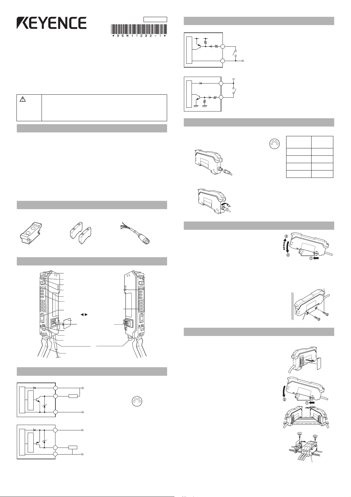
Part Names
1
2
DSC
12
Fiber lock lever
Operation status indicators (output 1)
Operation status indicators (output 2)
SET button (SET)
DSC indicator
Digital monitor
Manual button
( )
Expansion protective cover
Expansion connector
Channel selection
MODE button (MODE)
Output selector (L/D ON)
Dust cover
(Displayed in green)
(Displayed in red)
*
Dedicated for FS-V33C(P)/34C(P)
OP-73864 (cable length: 2 m)
OP-73865 (cable length: 10 m)
Setting value
Current value
2
1
DSC
1
2
FS-V33P/34P
12 to 24 VDC
Brown*
PLC, etc.
Pink (input)
Sensor main circuit
(Short-circuit
current 2 mA
or less)
Socket Cable (Sold Separately for FS-V33C (P)/V34C (P))
Connecting the Socket Cable
1 Connect the socket to the pin on the
amplifier.
412
3
2 Turn the fixing ring on the socket clockwise to fix the socket.
Mounting Unit
Mounting on a DIN Rail
1
Align the claw at the bottom of the main body with the
DIN rail. While pushing the main body in the direction
of the arrow 1, slant it in the direction of the arrow 2.
2
To dismount the sensor, raise the main body in
the direction of the arrow 3 while pushing the
main body in the direction of the arrow 1.
Installation on a Wall (Main Unit Only)
Attach the unit to the optional mounting bracket
(OP-73880), mount them together, and secure
them with two M3 screws as shown in the illustration.
Connecting Multiple Amplifiers
Up to 16 sub units can be connected to one main unit.
1 Remove the protection cover on the side of
the main unit.
Output Circuit Diagram
FS-V33(C)/34(C)
FS-V33 (C)P/V34(C)P
123
2 Install the amplifier one by one on the DIN rail.
4
3 Engage the two claws of the child unit with the
recesses on the main unit side until you hear a
click sound.
4 Attach the end units (option: OP-26751) to the
both ends of the connected amplifiers in the
same way as in step (2).
5
Sandwich the amplifiers between the end units.
Tighten the screws at the top (two screws x two
units) with a Phillips screwdriver to fix the end units.
1
Page 2
Connecting Fiber Unit
Note
Transmitter
Receiver
Single-core fiber
Multi-core fiber
Brown *
Blue *
Pink
+V
0V
FS-V33/V34 FS-V33P/V34P
Input OFF
Input ON
% calibration Display scaling
3 seconds
or less
Input OFF
Input ON
% calibration% calibration
3 seconds or more
DSC
2
1
Workpiece
DSC
When the setting is completed,
the setting value is displayed.
2
1
DSC
2
1
3 sec or longer
Reflective
Thrubeam
DSC
2
1
Workpiece
When the setting is completed,
the setting value is displayed.
DSC
2
1
Workpiece
DSC
2
1
When the setting is completed,
the setting value is displayed.
Edge
Workpiece
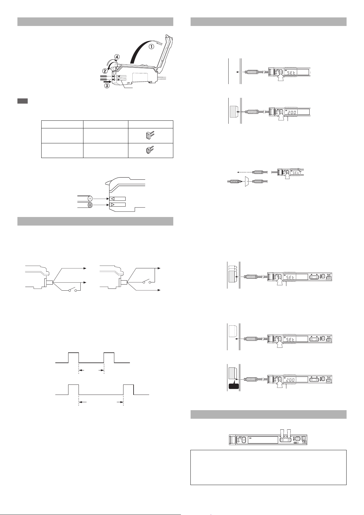
1 Open the dust cover in the
direction shown by arrow 1.
2
Move down the fiber lock lever in the
direction shown by arrow 2.
3
Insert a fiber unit into the fiber insertion holes
to a length of the fiber insertion sign (i.e.,
approximately 14 mm).
4
Move down the fiber lock lever in the
direction shown by arrow 4.
If a thin fiber unit is used, an adapter provided with the thin fiber unit will be required.
Unless the right adapter is connected, the thin fiber unit will not detect targets correctly. (The
adapter is supplied with the fiber unit.)
Cable outer dia. Adapter Appearance
φ1.3
φ1.0
Adapter A
(OP-26500)
Adapter B
(OP-26501)
• To connect the coaxial reflective type fiber unit to the amplifier, connect the single-core fiber to the transmitter side, and connect the multiple-core fiber to the
receiver side.
External Input
1
Signals can be input externally by selecting an external input function (page 5, No. 5).
2
The signal can be accepted by short-circuiting the pink wire for 2 ms or more as
shown below for each model (20 ms for OFF).
Fiber insertion sign
Making Sensitivity Settings
Two-point Calibration
In this mode, the setting value used will be the mean value of two sensing values
obtained with and without a workpiece.
1
Press the SET button without any workpiece placed in front of the fiber unit.
2
Place a workpiece placed in front of the fiber unit, and press the SET button.
If the sensitivity difference does not have enough room, “
” flashes for about two seconds
after the calibration is complete. The set value is stored in memory even in that case.
Maximum Sensitivity Setting
Set the sensitivity without a workpiece in the case of the reflective model, and with a
workpiece in the case of the through-beam or retro-reflective model.
Press the SET button for three seconds in the state as shown in the above figure.
(Release the button when SET flashes.) The setting value is set slightly higher than
the received light intensity at the time of setting the sensitivity.
Full Auto Calibration
In this mode, the setting value will be set to the mean value of the maximum and
minimum incident values obtained within a certain period.
Use this mode to detect moving workpieces.
1 Press the set button for a minimum of three seconds while the target
workpiece is passing the sensing area of the fiber unit.
• While the set button is pressed, the sensitivity of the sensor will be set
according to the incident values.
* FS-V33/V33P only.
* Setting using an external input is up to 1 million times.
* No inputs are accepted while setting each mode.
Brown *
Pink
Blue *
+V
0V
When external calibration is selected, the operation is the same as with the SET button.
Special Function
By performing the following operation, both sensitivity setting and scaling can be performed using external input.Select external calibration (page 5, No. 5) and display scaling
(page 6, No. 7).The following is the example when using the % calibration.
• After the setting is completed, the setting value is displayed on the digital monitor.
Positioning Calibration
1
Press the SET button without any workpiece placed in front of the fiber unit.
2 Place a workpiece on the position where you want to perform positioning.
Press the SET button for 3 seconds or longer until the display flashes.
Fine-adjusting Sensitivity
The setting value can be directly changed by pressing the manual button.
DSC
1
122
When extended display (page 6, No. 9) is set for the number of digits to be
displayed for the received light intensity
1
Press the manual button quickly once, and check that the setting value flashes.
2
While the setting value is flashing, change the setting value with the Manual button.
2
Page 3
Percentage Calibration
DSC
122
1
Press
Press (2) within 5 seconds
after pressing (1).
(1)
(2)
122
When Area, Limit setting,
Counter, or Alarm is selected,
the selection options are
NO and NC.
DSC
1
DSC
122
1
This is a calibration method that can set the setting value by percentage with reference to the received light intensity at the time of sensitivity setting.
For example, if the target value is set to -10P, the setting value is determined 10%
lower than the received light intensity when the SET button is pressed.
1 When selecting the sensitivity setting method (page 5, No. 2), select the %
calibration, and set the target value of calibration.
2 Taking the desired light intensity as a reference (normally without a
workpiece), press the SET button.
While the % calibration is in use, other calibrations (sensitivity setting) cannot be used.
*
Output Selection
Either light-ON mode or dark-ON mode is selectable.
Dynamic Sensitivity Correction (DSC) Function
DSC automatically corrects the setting value according to the changes in the
received light intensity when there is no workpiece (output OFF).
This function is effective when the light intensity difference is small when judging
whether or not there is a workpiece.
At Detection mode selection (page 5, No.4), select “Dynamic sensitivity correction
mode” beforehand.*
How to set the sensitivity is the same as in the normal mode.
The DSC indicator illuminates when the DSC function is set.
DSC indicator
DSC
1
* When Light ON is selected, the upper limit of the correctable range is twice as
much as the initial setting value.
* The value is stored in memory even after the power is turned off.
* The DSC indicator flashes when the light intensity during output OFF greatly
fluctuates or the L/D ON selection is inappropriate. In such a case, check the
setting again.
122
Area Detection Mode
This mode is suited to detecting the received light intensity only of a certain range.
To set this mode, select the area detection mode at Detection mode selection (page 5, No.4).
OFF
ON
OFF
HI: Upper limit setting value
LO: Lower limit setting value
Received light
intensity
Set the value so that the upper limit setting value is larger than the lower limit setting value. The unit does not respond when the upper limit setting value is less
than or equal to the lower limit setting value.
Even when the above condition is satisfied, the unit may not respond when the HI and LO values are close
to each other because of hysteresis. Be sure to operate the unit to check whether the values are valid.
How to Switch the Upper Limit Setting Value (HI) and the Lower
Limit Setting Value (LO)
When the button is pressed, HI or LO and the setting value alternately flash.
When the MODE button is pressed while the display alternately flashes, the HI or
LO display changes. How to configure the sensitivity setting is the same as when
in the normal detection mode.
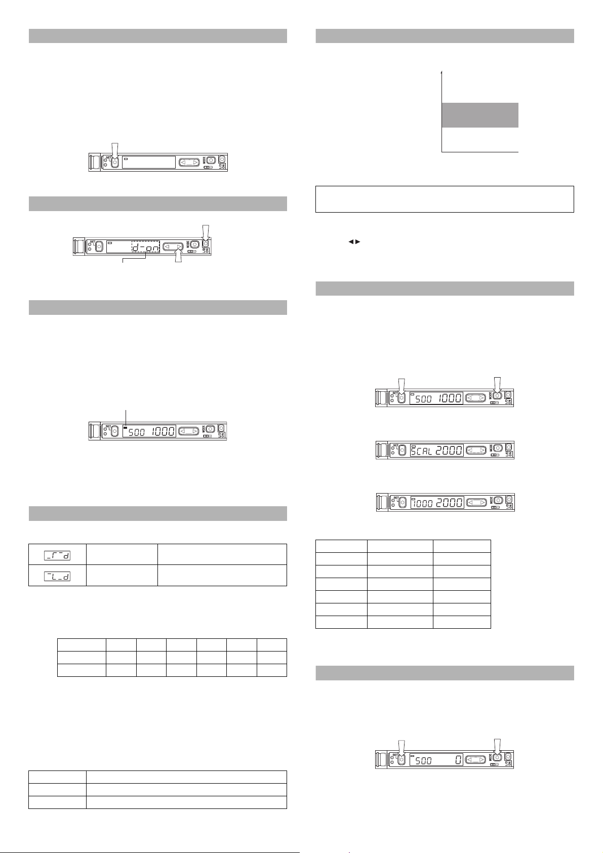
Setting the Display Scaling
This is the function to adjust the current received light intensity to the ìscaling target value.
1 When selecting a display value correction function (page 6, No. 7), select the
display scaling function, and set the target value. (The explanation here deals
with the case where the target value is set to 2000.)
2
During the normal display, press the SET button while pressing the MODE button.
(Scaling is performed for the current light intensity at this time.)
DSC
1
The display changes as follows, and the target value (which is 2000) to be set
as a scale is displayed.
DSC
1
Ø
The scaled value is displayed.
122
122
Edge Detection Mode
This mode detects the change in the received light intensity during a given period
of time. (Set at page 5, No. 4)
Rising edge detection Detects the increase (rising edge) of the
Falling edge detection Detects the decrease (falling edge) of the
Filter Setting
Basically, leave this setting as its initial value. If the passage interval of workpieces
is too short for the unit to respond, strengthen the level and try again.
The selectable filter level differs depending on the power modes.
Filter level HSP* FINE
Default state589999
Setting range 1 to 5 4 to 8 5 to 9 6 to 9 8 to 9 9 only
*HSP: HIGH SPEED
As the number becomes smaller, the filter becomes stronger, which makes the unit difficult to
respond to gradual changes in light intensity.
Making Sensitivity Settings
The sensitivity is set to maximum when the SET button is pressed quickly once.
When the setting value is too low and the unit detects objects other than the workpiece, fine-adjust the setting value to a higher number.
Operation When Switching Outputs
Setting Operation
L-ON Normally OFF. Turns ON only when the light intensity changes.
D-ON Normally ON. Turns OFF only when the light intensity changes.
received light intensity
received light intensity
TURBO
SUPER ULTRA MEGA
The reference light intensity can be set in the following range in reference with the
currently received light intensity:
Power mode Minimum value Maximum value
HIGH SPEED Approx. 1/20 times Approx. 16 times
FINE Approx. 1/20 times Approx. 16 times
TURBO Approx. 1/20 times Approx. 16 times
SUPER Approx. 1/40 times Approx. 8 times
ULTRA Approx. 1/160 times Approx. 2 times
MEGA Approx. 1/320 times Approx. 1 time
If the value exceeds the
range,
'TT
is displayed
and scaling is performed up
to the possible range.
• No value can be set when the Edge detection mode is selected.
• The value is stored in memory even after the power is turned off.
• External input can be used when using FS-V33(P)/34(P) (page 5, No.5).
Zero-shift Function
The Zero-shift function is used to forcibly set the current light intensity to zero.
1
At Display value correction function selection (page 6, No.7), select “Zero-shift function”.
2 When the SET button is pressed while the MODE button is pressed, the current
light intensity is forcibly set to zero.
DSC
1
• This function cannot be used when the Dynamic sensitivity correction (DSC) or
Edge detection mode is selected.
• The value is stored in memory even after the power is turned off.
• External input can be used when using FS-V33(P)/34(P) (page 5, No.5).
3
122
Page 4

Display Selection
Press
MODE
DSC
DSC
Press for 2 seconds
or longer.
.
.
.
.
.
Hold display selection
Select the setting by pressing the button.
Updates every time the current light
intensity is less (or more) than the specified
peak and bottom values.
Displays the maximum and minimum peak
values since the power is turned on (total
number).
Displays the maximum and minimum
bottom values since the power is turned on
(total number).
Displays the minimum peak value and the
maximum bottom value since the power is
turned on (total number).
Displays the maximum peak value and the
minimum bottom value since the power is
turned on (total number).
The factory default value is “1” only. Other items can be displayed only after being
selected at Display customization selection (page 6, No. 8).
(1) (7)
DSC
Parameter Current received
(2)
Extension display
(received light intensity) *1
(3)
Bar display *2
(4)
Bar display *2 Excess gain (%) *3
DSC
DSC
DSC
light intensity
MODE
Press
MODE
Press
Current received
light intensity
MODE
Press
*1 When ULTRA/MEGA mode is selected, the current received light intensity can
be displayed up to 5 digits. The setting value flashes when the button is
pressed once.
The setting can be changed by pressing the button while flashing.
*2 The excess gain is displayed in a 5% increment from 85 to 115%.
*3 The current light intensity for the setting value is displayed in percentage.
*4 Holds and displays the peak value and the bottom value.
How to reset peak or bottom value (with the (5)/(6) display)
The value can be reset by pressing the SET button for 3 seconds or more while
pressing the MODE button.
With FS-V33(P)/34(P), the value can be reset externally by selecting Reset at
External input function selection (page 5, No.5).The peak/bottom value is also
reset after the power is turned off.
User-friendly Functions (Direct Access Menu)
The hold display (5/6) can be set in detail by pressing the button for 2 seconds or longer.
Press
Press
MODE
MODE
DSC
Power mode
(6)
DSC
DSC
Excess gain (%)
Hold value
*4
(5)
DSC
DSC
Received light
intensity
Hold value *4
Current received
light intensity
MODE
Press
Excess gain (%)
Hold value
*4
MODE
Press
Received light
intensity
Hold value *4
Key Lock Function
The key lock function disables the operation of all keys.
1 While pressing the MODE button, press the ( ) button for at least three
seconds.
DSC
1
122
The same steps can be taken to deactivate key lock.
By selecting the key lock (page 6, No.12) level (1-3), key operations to be disabled can be changed.
(The default value is level 1.)
Basic Operations Button
Sensitivity Setting (p.3)
SET °cc
Sensitivity fine-adjustment (p.3)
Channel selection (p.1) Channel selection switch ccc
Output selection (p.2) L/D ON °°°
Menu selection (p.5) Press and hold MODE
Advanced Operations Button
Initialization (p.2) L/D ON + press and hold SET °°°
Display scaling (p.4) MODE + quickly press SET °cc
Zero shift (p.4) MODE + quickly press SET °cc
Direct access menu (p.7)
Display OFF/ON (p.6)
c: Normal operation is possible.
°: Operation is not possible.
Press and hold
L/D.ON + press and hold MODE
: The settings can be checked but cannot be changed.
Level
123
cc
°°
Level
123
°°
ccc
PIN Number Key Lock Function
The unit can be locked using a PIN number to ensure securer locking effect.
1 While pressing the MODE button, press the ( ) button 10 times.
The power mode and emission power for the power mode display (7) can be
switched by pressing the button for 2 seconds or longer.
DSC
Press for 2 seconds or longer.
DSC
Press
DSC
Press
Press to select (see page 5, No. 1).
MODE
Press to select (see page 5, No. 5).
MODE
DSC
1
122
2 Select a PIN number between 0 and 9999 using the button.
3 Press the MODE button to activate key lock.
Follow the same step to disable the key lock. Use the same PIN number used for
locking.
Note
Write down the PIN number in case it is forgotten. The key lock cannot be disabled unless the
correct PIN number is used.
4
Page 5

Operation Configuration
Basic
setting menu
1. Power mode selection
2. Sensitivity setting method selection
3. Timer mode selection
4. Detection mode selection
5. Light emission power selection
6. Display value correction function selection
7. Display reverse selection
8. Display customization selection
9. APC function setting
10. Power save mode setting
11. Key lock level setting
12. Interference prevention function setting
Detection
setting menu
Display
setting menu
System
setting menu
Normally, this unit can be used in the basic settings.
Set other functions as necessary.
Pressing for 3 seconds or longer displays the basic menu.
Select a function with the button, and press to confirm.
MODE
MODE
The setting for each item is confirmed when selecting END and pressing .
Basic Setting Menu
Set the channel selection switch to "1".
MODE
Press for 3 seconds or longer
DSC
Press
DSC
Press
When Std is
selected
A
DSC
Press
When StG-Func
is selected
When StG-diSP
is selected
When StG-SYS
is selected
When End is
selected
End of basic menu
display
MODE
MODE
DSC
MODE
When SEtP
is selected
Detection
Display
System
1 Power mode (response time) selection
Select the setting by pressing the button.
.
.
.
.
.
.
2 Sensitivity setting method selection
Select the setting by pressing the button.
.
.
Percentage calibration target value setting
Select the setting by pressing the button.
MODE
Press
Can be set between –99 and +99%.
Menu end/continue selection
Select the setting by pressing the button.
.
.
.
.
HIGH SPEED: 33 µs
FINE: 250 µs
TURBO: 500 µs
SUPER: 1 ms
ULTRA: 4 ms
MEGA: 16 ms
(Can be switched when the power
selection switch is set to SEL.)
Normal sensitivity setting (see page 2)
% calibration (see page 2)
12
Channel selection switch
Ends the menu.
Configures detection
settings.
(Timer, DSC, etc.)
Configures display
settings.
(Scaling, inversion, etc.)
Configures system
settings.
(APC, Power Save, etc.)
MODE
Detection Setting Menu
From the basic menu
DSC
MODE
Press
DSC
MODE
Press
DSC
a
DSC
DSC
MODE
Press
DSC
DSC
DSC
When using
FS-V33(P)/
34(P)
MODE
Press
DSC
When other
than VQ((
is selected
b
or
When dSc is
selected
When Edge detection
is selected
When VQ(( is
selected
DSC
When Std or
ArEA is selected
When using
FS-V33C(P)/
34C(P)
DSC
When other
than SCAL is
selected
DSC DSC
3
Timer mode selection
Select the setting by pressing the button.
Timer OFF
OFF-delay
ON-delay
One-shot
Timer setting
Configure setting by pressing the button.
MODE
Press
Press
Press
Press
Press
When SCAL
is selected
Can be set between 0.1 and 9999 ms.
When 1 is selected, ON-delay timer is set.
At Timer mode selection,
* other than 1 is selected a
* 1 is selected b
Timer setting 2
Sets the time of OFF-delay (One-shot).
Configure setting by pressing the button.
Can be set between 0.1 and 9999 ms.
MODE
4
Detection mode selection
Select the setting by pressing the button.
.
Normal (light intensity) detection mode
.
Dynamic sensitivity correction mode
(see page 3)
.
Area detection mode (see page 3)
.
Detects the rising edge of the received
light intensity (Edge detection mode)
(see page 3)
.
Detects the falling edge of the received
light intensity (Edge detection mode)
(see page 3)
Detection operation selection
Select the setting by pressing the button.
MODE
.
Mainly reflective
[Light intensity with workpiece >
Light intensity without workpiece]
(The output is ON when the light
enters.)
.
Mainly thrubeam
[Light intensity with workpiece <
Light intensity without workpiece]
(The output is ON when the light
is blocked.)
Correction speed selection
Select the setting by pressing the button.
MODE
1 to 3
The correction is made faster as the number
becomes larger. (Select 1 in normal cases.)
Power mode
hSP
FinE
Turb/SuPr/Ultr/MEGA
Filter time selection
Select the setting by pressing the button.
MODE
Select larger number (initial state) in normal
cases. The selectable level depends on the
power modes. (see page 3)
5
External input function selection
Select the setting by pressing the button.
• Does not use external input.
• External calibration
• Display scaling
•
• Reset
• Emission stop
Display scaling target value setting
Select the setting by pressing the button.
MODE
Press
The value can be set between 100 and
10000 in the unit of 100.
10000 is displayed as FuLL.
ON-delay OFF-delay *1
ON-delay One-shot *1
Level 1
Level 2
114.7ms
7.34s
819.2ms
52.43s
1.64s
104.86s
Zero-shift
Level 3
1.8ms
12.8ms
25.6ms
A
Press
MODE
6
Light emission power selection
Select the setting by pressing the button.
Display
Power mode
FinE
hSP
Normal
Approx. 15% of the normal time
Approx. 3% of
Approx. 11% of
the normal time
the normal time
Turb/SuPr/
uLtr/MEGA
Approx. 1.5% of
the normal time
5
Page 6

Display Setting Menu System Setting Menu
Select the setting by pressing the button.
Not to be used.
Uses the display scaling function.
Uses the zero-shift function.
Display scaling target value setting
Configure setting by pressing the button.
The value can be set between 100 and
10000 in unit of 100.
10000 is displayed as FuLL.
When oFF or
ShFt is selected
When no is
selected
When SCAL
is selected
DSC
DSC
DSC
DSC
DSC
DSC
DSC
DSC
DSC
DSC
DSC
Select the setting by pressing the button.
Normal display
Reverses the display.
Even when the display is reversed,
the green light indicates setting values,
and the red light indicates received
light intensity.
Select the setting by pressing the button.
Does not customize the display.
Customizes the display.
Selectable display setting
The items shown left are displayed in
order every time the MODE button is
pressed. (see page 3)
Select the setting by pressing the
button.
Adds the item to the
selectable display.
Deletes the item from the
selectable display.
When no is
selected
Normal
Expansion
Extension
bar
Excess gain
(%)
HOLD
Power mode
HOLD
Excess gain
(%)
7
Display value correction function selection
8
Display reverse selection
9
Display customization selection
(1)
(2)
(3)
(4)
(5)
(7)
(6)
Press
MODE
Press
MODE
Press
MODE
Press
MODE
Press
MODE
Press
MODE
Press
MODE
Press
MODE
Press
MODE
Press
MODE
Press
MODE
Press
MODE
.
.
.
.
.
.
.
.
.
From the basic menu
Back to A of
the basic setting.
When setting each mode, the display returns normal by pressing the
button for 3 seconds or longer.
MODE
L/D
ON
From the basic menu
DSC
DSC
DSC
DSC
Press
Press
Press
Press
DSC
Press
Back to A of
the basic setting.
MODE
MODE
MODE
MODE
MODE
9
S-APC setting
Configure setting by pressing the button.
.
APC is enabled.
.
APC is disabled.
About APC (Auto Power Control)
In normal cases, use the sensor with APC
disabled.
When APC is enabled, the light intensity is
monitored and corrected in order to maintain
regular light transmission. If the environment is
sufficiently clean, a highly accurate detection can
constantly be performed.
Note: Long-ter m use of APC imposes heavier
load on the LED than when disabled.
10
Power save mode setting
Configure setting by pressing the button.
.
Saves power (Turns off the display).
While the power save mode is
activated, only one segment on the
digital monitor remains displayed.
.
Normal display
To turn all the displays OFF (both digital
monitor and operation status indicators)
ALL can be selected when is pressed for 3
seconds or longer while “on” is selected.
To restore the display from Display OFF, press
MODE and L/D ON buttons simultaneously for 3
seconds or longer.
11
Key lock level setting (see page 6)
Select the setting by pressing the button.
.
Level 1
.
Level 2
.
Level 3
12
Selecting the number of units of interference prevention
Select the setting by pressing the button.
.
Normal
.
The number of units of interference
prevention is twice as many as in the
normal time. (The response time is also
twice as long as in the normal time.
The detection distance is the same
as in the normal time.
)
Reference
Initializing, Saving and Loading the Settings
Initializing the settings
1 While pressing , press for 5 seconds or longer.
2 Select “T5V“with the button, and press .
3 Select “PV” with the button, and press to initialize.
Default setting
Power mode: FAIN
Detection mode: Normal
Setting value: 50
Output selection: L ON
Saving the Settings
1 While pressing , press for 5 seconds or longer.
2 Select “5#X'” with the button, and press .
3 Select “;'5” with the button, and press to save.
Loading the setting
1 While pressing , press for 5 seconds or longer.
2 Select “T5V” with the button, and press .
3 Select “=X5V” with the button, and press to load.
L/D
ON
L/D
ON
SET
MODE
MODE
SET
MODE
MODE
SET
MODE
MODE
6
Page 7

Channel Selection Switch 2 Special Functions of Channel 2
To set channel 2, set the channel
selection switch to "2".
DSC
MODE
Press for 3 seconds or longer
DSC
When Std
is selected
DSC
DSC
DSC
DSC
When ovr1/ovr2
is selected
DSC
Output 2 function selection
Select the setting by pressing the button.
• Normal (light intensity) detection
• Used as limit setting output.
• Used as counter output.
• Used as alarm output.
When LiMt
is selected
MODE
Press
(Instantaneous display)
(Normal display)
When Cnt
is selected
MODE
Press
When Auto
is selected
MODE
Press
12
Channel selection switch
Limit function setting
Select the setting by pressing the button.
• Sets the peak value.
• Sets the bottom value.
Counter function setting
Select the setting by pressing the button.
• Over count mode 1
• Over count mode 2
• Auto reset mode
One-shot time setting
Select the setting by pressing the button.
The value can be set between 0.1 and
9999 ms.
Limit Setting
This function issues a prediction alarm when the light intensity difference is small
when judging whether or not there is a workpiece.
Two types of limit setting function are available:
Peak limit setting
Samples the peak values of setting value while the received light intensity is
higher than the output 1 setting value, and issues an alarm when the minimum
peak value is lower than the output 2 setting value.
Bottom limit setting
Samples the bottom values of setting value while the received light intensity is
lower than the output 1 setting value, and issues an alarm when the maximum bottom value is higher than the output 2 setting value.
Bottom hold maximum value
1ch output
2ch output (PEAk setting value)
2ch output (botm setting value)
Channel 2 normal display when using the limit setting function
DSC
Pressing the button
Alternate
can adjust the setting value.
DSC
Setting value
How to reset the peak/bottom value
The value can be reset by pressing the SET button for 3 seconds or more
while pressing the MODE button.
With FS-V33(P)/34(P), the value can be reset externally by selecting Reset at
External input function selection (page 5, No.5). The peak/bottom value is also
reset after the power is turned off.
display
Peak/bottom value
Peak hold minimum value
Setting value when
PEAk is selected
1ch value
Setting value when
botm is selected
DSC
(Instantaneous display)
Counter Function
This mode counts the output (edge of OFF to ON) of output 1, and compares it
with the setting value.
DSC
When AlrM
DSC
DSC
DSC
DSC
(Instantaneous display)
(Normal display)
(Normal display)
is selected
(Instantaneous display)
(Normal display)
The following three count modes are available:
Q7T
Over counter 1
Q7T
Over counter 2
#XVQ
Auto reset
The output turns ON with the value higher than the setting
value.The counter value increases until it is reset.
The output turns ON only when the value is the same as the
setting value.The count value increases until it is reset.
One-shot output is performed when the value is the same as the
setting value, and the count value is automatically reset.
Channel 2 normal display when using the counter function
DSC
Alternate
display
DSC
Setting value Count value
Pressing the button
can adjust the setting value.
The setting value can be displayed
up to 65.535 on the Extension display
(page 6, No. 9).
How to reset the count value
The value can be reset by pressing the SET button for 3 seconds or more
while pressing the MODE button.
With FS-V33(P)/34(P), the value can be reset externally by selecting Reset at
External input function selection (page 5, No.5). The count value is also reset
after the power is turned off.
Alarm Output Function
When using the APC function, the alarm output is issued when the load on the LED is too
large.The alarm output is also issued when the DSC indicator is flashing (refer to
Dynamic Sensitivity Correction (DSC) Function on page 4).
Channel 2 normal display when using the alarm output function
When the load on
Normal
DSC DSC
the LED is greater
7
Page 8

Copyright (c) 2010 KEYENCE CORPORATION. All rights reserved.
11292E 1070-1 96M11292 Printed in Japan
Specifications
Power mode
HIGH SPEED
FINE
TURBO/SUPER/ULTRA/MEGA
Number of units
required to pre-
vent interference
0 units 4 units 8 units
Power mode
HIGH SPEED
FINE
TURBO/SUPER/ULTRA/MEGA
Number of units
required to pre-
vent interference
0 units 8 units 16 units
Typ e
Model
Control
output
(2 outputs)
Response time
Number of
interference
prevention
units
Power
consumption
Operating
ambient
luminance
Operating ambient tempera-
Operating ambient humidity 35 to 85% RH (No condensation)
Vibration resistance
Weight (including cable) Approx. 80g Approx. 70g Approx. 22g
*1 When several units are connected, the operating ambient temperature varies depending
on the number of units to be connected. When connecting several units, be sure to
mount the units on the DIN rail (mounted on a metal plate), and keep the output current
within 20 mA.
When 1 to 2 units are connected: -10 to +55 °C,
When 3 to 10 units are connected: -10 to +50 °C,
When 11 to 16 units are connected: -10 to +45 °C
When using the 2-output type, count one unit as two units.
*2 When double is set, the response time is twice longer. When using the 2-output type, be
careful with the number of units to be connected.
*3
When using the HIGH SPEED mode, the power consumption increases by 160 mW (7 mA).
NPN output FS-V33 FS-V34 FS-V33C FS-V34C
PNP output FS-V33P FS-V34P FS-V33CP FS-V34CP
Light source Red 4-element LED (peak wave length: 640 nm typ.)
NPN output NPN open collector 24 V 100 mA (2CH total) max
PNP output PNP open collector 24 V 100 mA (2CH total) max
*1
ON/OFF
output
Control input
Normal time
When
double is set
*2
Timer function
Power voltage 12-24 VDC, Ripple (P-P): 10% max, Class2
NPN output
*3
Shock resistance
PNP output
Incandescent
lamp
Sun light 30,000 lx max.
ture
Material Main unit, housing material: Polycarbonate
Cable type Connector type
Main unit Sub unit Main unit Sub unit
33 μs (HIGH SPEED)/250 μs (FINE)/500 μs (TURBO)/
1 ms (SUPER)/4 ms (ULTRA)/16 ms (MEGA)
Calibration/Scaling/
Zero-shift/Reset/Emission
stop(input time ON: 2 ms, OFF:
Power saving 660 mW max. (Using 24 V, 27 mA max., using 12 V, 32 mA max.)
20 ms)
Timer OFF/Off-delay/On-delay/One-shot/
On-delay Off-delay/On-delay One-shot
(Timer time: 0.1 ms to 9999 ms)
Normal: 710 mW max. (Using 24 V, 29 mA max., using 12 V, 40 mA max.)
Power saving: 540 mW max. (Using 24 V, 22 mA max., using 12 V, 28 mA
830 mW max. (Using 24 V, 35 mA max., using 12 V, 45 mA max.)/
-10 to +55 °C (No freezing)
10 to 55 Hz Compound amplitude 1.5 mm,
2 hours for each of XYZ axes
500 m/s
max.)
20,000 lx max.
2
3 times for each of XYZ axes
–
Hints On Correct Use
• Do not wire the amplifier line along with power lines or high-tension lines, otherwise the sensor may malfunction or receive damage due to noise.
• When using a commercially available switching regulator, ground the frame
ground terminal and ground terminal.
• Do not use the FS series outdoors, or in a place where extraneous light can
enter the light-receiving surface directly.
• Due to the individual dispersion of characteristics and the difference in fiber
unit model, the maximum sensing distance or displayed value of all the units
are not the same.
•I
f the sensor is used in S-APC mode for a long time, the LED indicators will be imposed
with a heavy load. In that case, the sensor will be automatically set to ACC mode where
the current consumption of the sensor for light emission will be constant, and “END
APC” will be displayed. The sensor can be continuously used in this case. Replace the
sensor, however, if highly precise detection is required.
WARRANTY
KEYENCE products are strictly factory-inspected. However, in the event of a failure,
contact your nearest KEYENCE office with details of the failure.
1. WARRANTY PERIOD
The warranty period shall be for one year from the date that the product has been
delivered to the location specified by the purchaser.
2. WARRANTY SCOPE
(1) If a failure attributable to KEYENCE occurs within the abovementioned warranty
period, we will repair the product, free of charge. However, the following cases shall
be excluded from the warranty scope.
• Any failure resulting from improper conditions, improper environments, improper
handling, or improper usage other than described in the instruction manual, the
user’s manual, or the specifications specifically arranged between the purchaser
and KEYENCE.
• Any failure resulting from factors other than a defect of our product, such as the
purchaser’s equipment or the design of the purchaser’s software.
• Any failure resulting from modifications or repairs carried out by any person other
than KEYENCE staff.
• Any failure that can certainly be prevented when the expendable part(s) is
maintained or replaced correctly as described in the instruction manual, the user’s
manual, etc.
• Any failure caused by a factor that cannot be foreseen at a scientific/technical
level at the time when the product has been shipped from KEYENCE.
• Any disaster such as fire, earthquake, and flood, or any other external factor, such
as abnormal voltage, for which we are not liable.
(2) The warranty scope is limited to the extent set forth in item (1), and KEYENCE
assumes no liability for any purchaser’s secondary damage (damage of equipment,
loss of opportunities, loss of profits, etc.) or any other damage resulting from a failure
of our product.
3. PRODUCT APPLICABILITY
KEYENCE products are designed and manufactured as general-purpose products
for general industries.
Therefore, our products are not intended for the applications below and are not
applicable to them. If, however, the purchaser consults with us in advance regarding
the employment of our product, understands the specifications, ratings, and
performance of the product on their own responsibility, and takes necessary safety
measures, the product may be applied. In this case, the warranty scope shall be the
same as above.
• Facilities where the product may greatly affect human life or property, such as
nuclear power plants, aviation, railroads, ships, motor vehicles, or medical
equipment
• Public utilities such as electricity, gas, or water services
• Usage outdoors, under similar conditions or in similar environments
E 1040-1
Error Displays and Corrective Actions
Error display Cause Corrective action
Overcurrent is flowing in the control
'T=
output.
Failed to write/read the internal data.
'T'
'PF#2=
The load on the light source is large.
Check the load and return the current
within the rated value.
Perform initialization (p.2).
If highly precise detection is required,
replace the sensor.
8
 Loading...