

Keyence BL-80 series Instruction Manual
Instruction
Manual
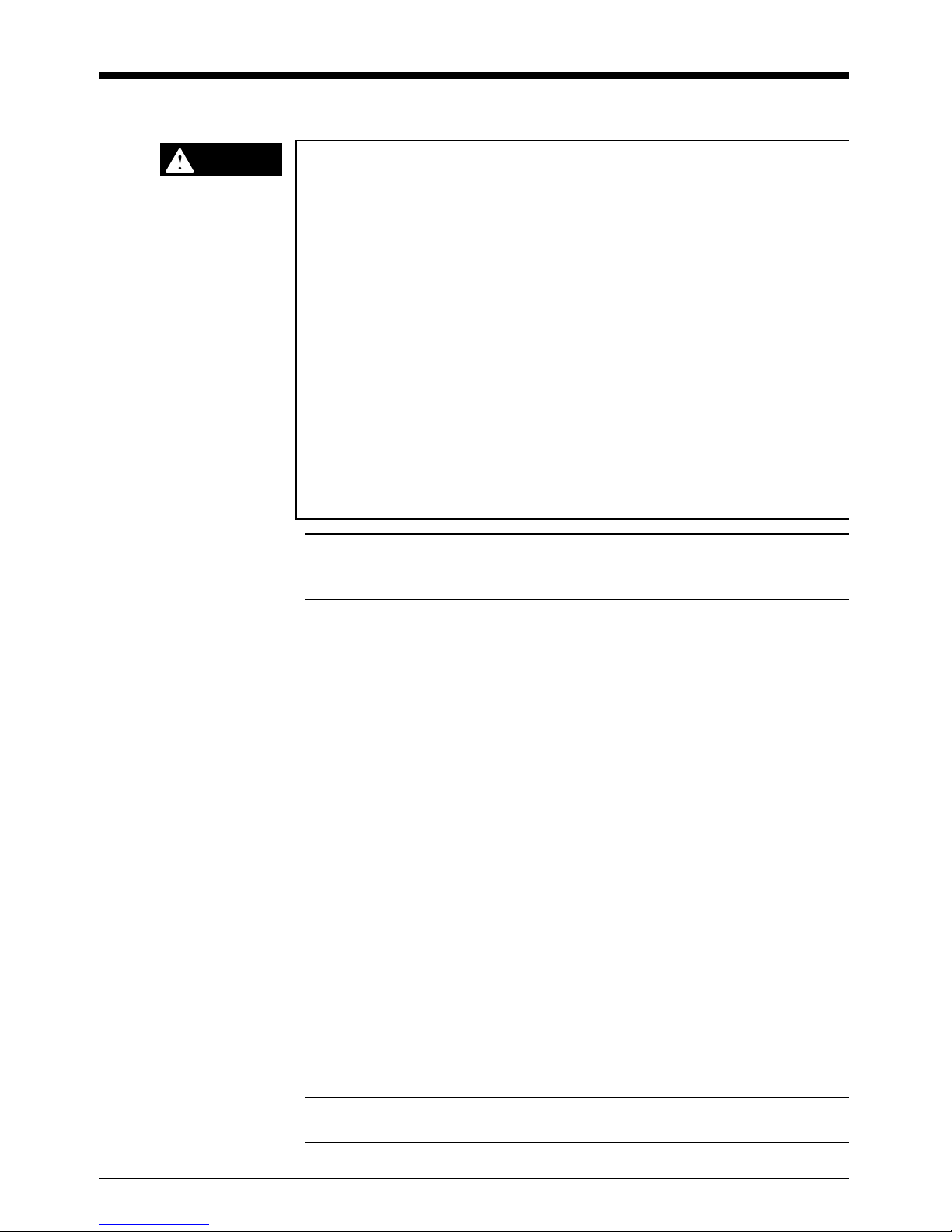
Handheld Bar Code Reader
BL-80 Series

Safety Precautions
This instruction manual describes the operation and function of the BL-80.
Read this manual carefully to ensure safe use and maximum performance
from your BL-80.
Symbols
The following symbols alert you to important messages. Be sure to read
these messages carefully.
Failure to follow instruction may lead to injury. (electric
shock, burn, etc.)
Failure to follow instructions may lead to product
damage.
Provides additional information on proper operation.
General Precautions
• At startup and during operation, be sure to monitor the functions and
performance of the BL-80.
• We recommend that you take substantial safety measures to avoid any
damage in the event a problem occurs.
• Do not open or modify the BL-80 or use it in any way other than
described in the specifications.
• When the BL-80 is used in combination with other instruments,
functions and performance may be degraded, depending on operating
conditions and the surrounding environment.
• Do not use the BL-80 for the purpose of protecting the human body.
Note:
i
CAUTION
WARNING
Warnings and Cautions Specific to the BL-80 Series
• When using the BL-80V(N)E (keyboard type), do not connect and
disconnect the cable while the personal computer turns on. This will
cause the bar code reader and the personal computer to be damaged.
• To use the BL-80RE (RS-232C type), be sure to use the AC adapter
included with the BL-80RE. Using other AC adapters may cause
product damage.
• Be sure to supply 120 VAC±10% to the AC adapter of the BL-80RE
(RS-232C type). Using other power supply types may cause product
damage.
• The BL-80 Series is a precision instrument. If the unit is dropped or
shocked, it may be damaged. Take due consideration when installing
the unit.
• Do not disassemble the BL-80 Series. A disassembled unit will not be
repaired.
• Please note that this product may not be compatible with all computers.
Note: The AC adapter included with the BL-80RE dose not comply with
the Low-voltage Directive (EC Directive). Use an AC adapter that complies
with the Low-voltage Directive if necessary.
ii
CAUTION
FCC NOTICE
This equipment has been tested and found to comply with the limits for a
Class A digital device, pursuant to Part 15 of the FCC Rules. These limits
are designed to provide reasonable protection against harmful interference when the equipment is operated in a commercial environment. This
equipment generates, uses and can radiate radio frequency energy and, if
not installed and used in accordance with the instruction manual, may
cause harmful interference to radio communications. Operation of this
equipment in a residential area is likely to cause harmful interference in
which case the user will be required to correct the interference at his own
expense.
The user may find the following booklet prepared by the Federal Communications Commission helpful:
"How to identify and Resolve Radio-TV Interference Problems".
This booklet is available from the U.S. Government Printing Office,
Washington, DC 20402, Stock No. 004-000-00345-4.
FCC Warning
The user is cautioned that changes or modifications not expressly
approved by the manufacturer could void the user's authority to operate
this equipment.
Note: In order for the installation of this product to maintain compliance
with the limits for a Class A device, shielded cable must be used.
Package contents list
Each BL-80 Series package includes the following components. Be sure
to check the package contents against the checklist before use.
BL-80VE
❏ BL-80VE unit
❏ AT-PS2 conversion connector (2 pcs.)
❏ Instruction manual
BL-80VNE
❏ BL-80VNE unit
❏ Instruction manual
BL-80RE
❏ BL-80RE unit
❏ AC adapter
❏ Instruction manual
BL-80RKE
❏ BL-80RKE unit
❏ Instruction manual
BL Series lineup
Model Description
BL-80VE DOS keyboard interface type
BL-80VNE DOS keyboard interface type for notebook-size
personal computer use
BL-80RE RS-232C type
BL-80RKE RS-232C type designed to connect KEYENCE products
OP-33250 Optional holder
iii

iv
Chapter 1 Connection
1.1 Part Names ................................................................................. 2
1.2 Connection ................................................................................. 3
Chapter 2 Operation
2.1 Reading Operation ..................................................................... 8
2.2 Double-reading Prevention Function ....................................... 8
2.3 Trigger Switch Operation .......................................................... 8
2.4 Data Format ................................................................................ 9
2.5 Settings for Keyboard Interface ............................................ 11
2.6 Communication Protocol [For RS-232C type only] .............. 12
Chapter 3 Setup Procedure
3.1 Changing the Settings ............................................................. 14
3.2 Bar Code Setup Menu ............................................................. 15
3.2.1 Start setting and complete setting codes.................................... 15
3.2.2 Settings for bar codes................................................................. 16
3.2.3 Function setting .......................................................................... 23
3.2.4 Data format setting ..................................................................... 25
3.2.5 Settings for the keyboard interface ............................................. 32
3.2.6 Setting for RS-232C ................................................................... 34
3.2.7 Hexadecimal digits setting bar code
(For entering values from 0 to F) ................................................ 36
Chapter 4 Appendix
4.1 Specifications .......................................................................... 38
4.2 Dimensions .............................................................................. 39
4.3 Sample Serial Communication Program
[for RS-232C type only] ........................................................... 42
4.4 ASCII Code Table ..................................................................... 43
4.5 Setting Parameter List and Factory Setting .......................... 44
Contents
WARRANTIES AND DISCLAIMERS 49

v

Chapter 1
Connection
1.1 Part Names .....................................................................2
1.2 Connection .....................................................................3
Chapter 1 Overview
1
2
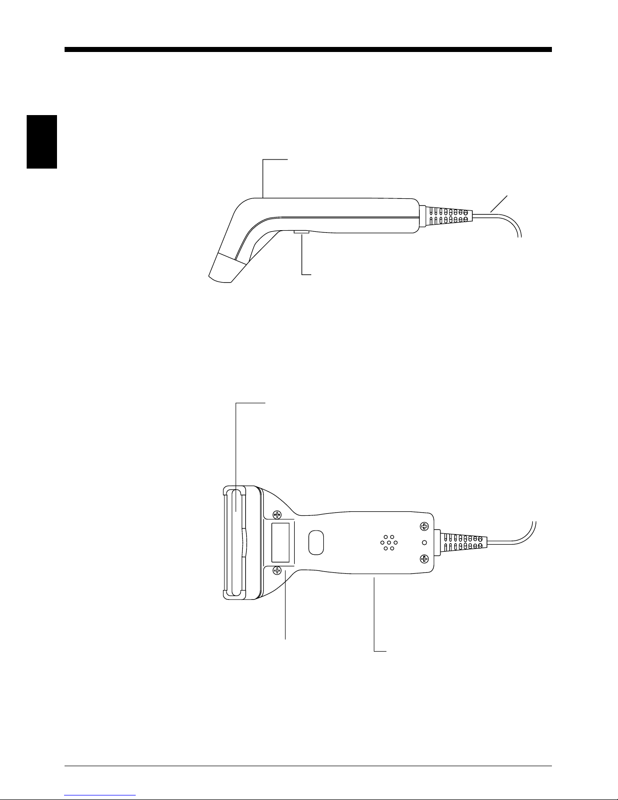
1.1 Part Names
Reading confirmation LED
Illuminates when a bar code is read.
Cable
Trigger switch
Press this switch to start reading.
Select from 5 trigger operation
modes according to the application.
➮ See p.8.
Read window
The BL-80 Series reads bar codes when they are
held to this window.
The light source LED inside the unit illuminates
while bar codes are read.
Trigger switch
Beeper
The beeper sounds when
a bar code is read or while
settings are changed.
Chapter 1 Overview
3
1
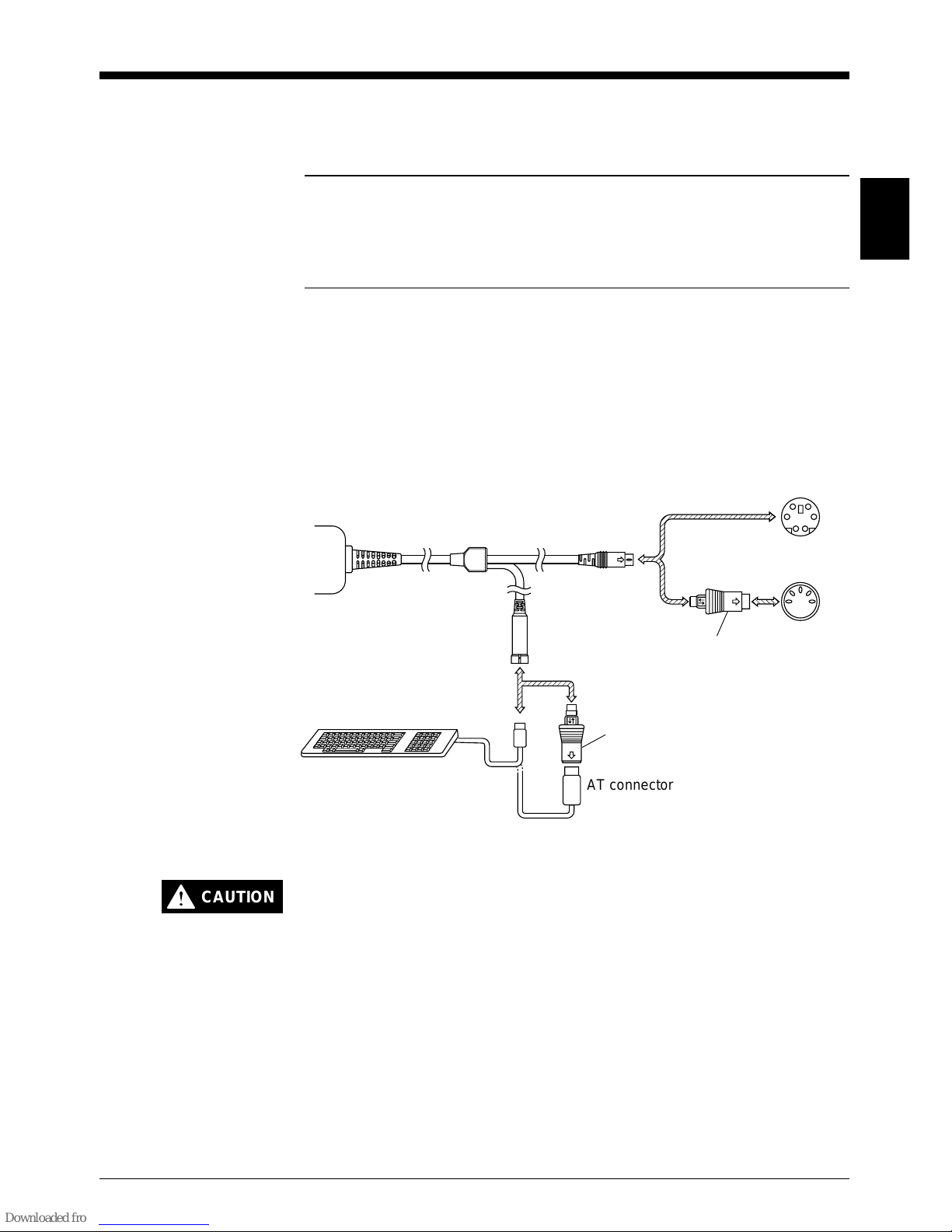
1.2 Connection
■ Connecting the BL-80VE
Note 1: Be sure to turn off the personal computer before connecting the
BL-80VE.
Note 2: Do not read bar codes with any keys held down. Do not use the
keyboard while uploading from the BL-80VE. Either of these actions will
affect correct data input.
Connect the BL-80VE to the keyboard connector of a DOS personal
computer as shown below. DOS computers have 2 possible types of
keyboard connectors: a PS2 connector and an AT connector.
If your computer has a PS2 connector, you can connect the BL-80VE
directly. If your computer has an AT connector, use the conversion
connectors as shown in the figure below. Power is supplied via the
keyboard connector.
Do not connect and disconnect the cable while the personal computer turns on. This will cause the personal computer and BL-80VE
to be damaged.
BL-80V
PS2 connector
(Mini DIN-6 pin)
Conversion
connector
AT connector
(DIN-5 pin)
Keyboard
PS2
connector
(To keyboard)
Conversion connector
(To PC)
AT connector
CAUTION
Chapter 1 Overview
1
4
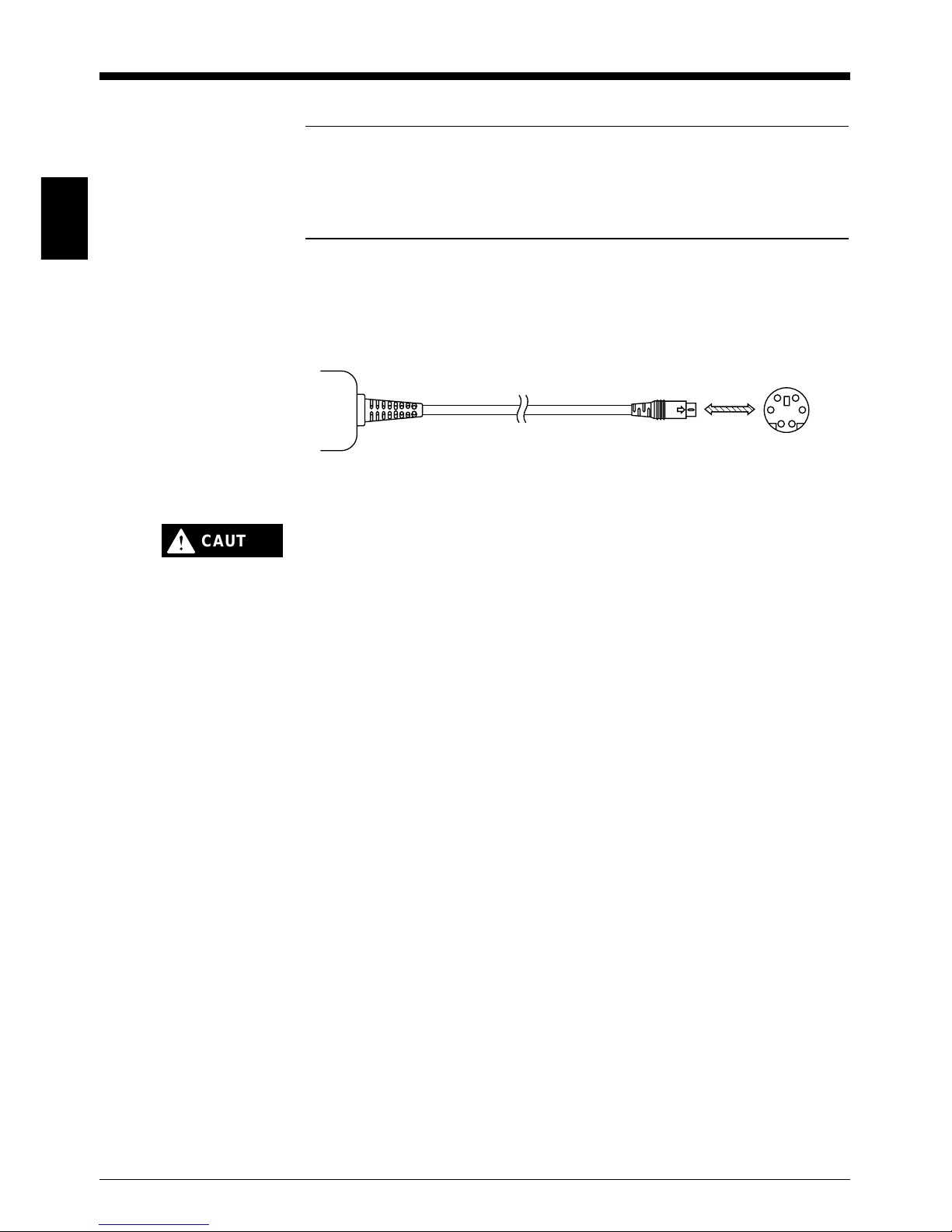
■ Connecting the BL-80VNE
Note 1: Be sure to turn off the personal computer before connecting the
BL-80VNE.
Note 2: Do not read bar codes with any keys held down. Do not use the
keyboard while uploading from the BL-80VNE. Either of these actions will
affect correct data input.
Connect the BL-80VNE to the mouse connector or the keyboard
connector of the DOS notebook-size personal computer as shown below.
Power is supplied via the mouse or the keyboard connector .
Do not connect and disconnect the cable while the personal computer turns on. This will cause the personal computer and BL-80VNE
to be damaged.
BL-80VNE
(To PC)
Keyboard
connector
(Mini DIN-6 pin)
CAUTION
Chapter 1 Overview
5
1
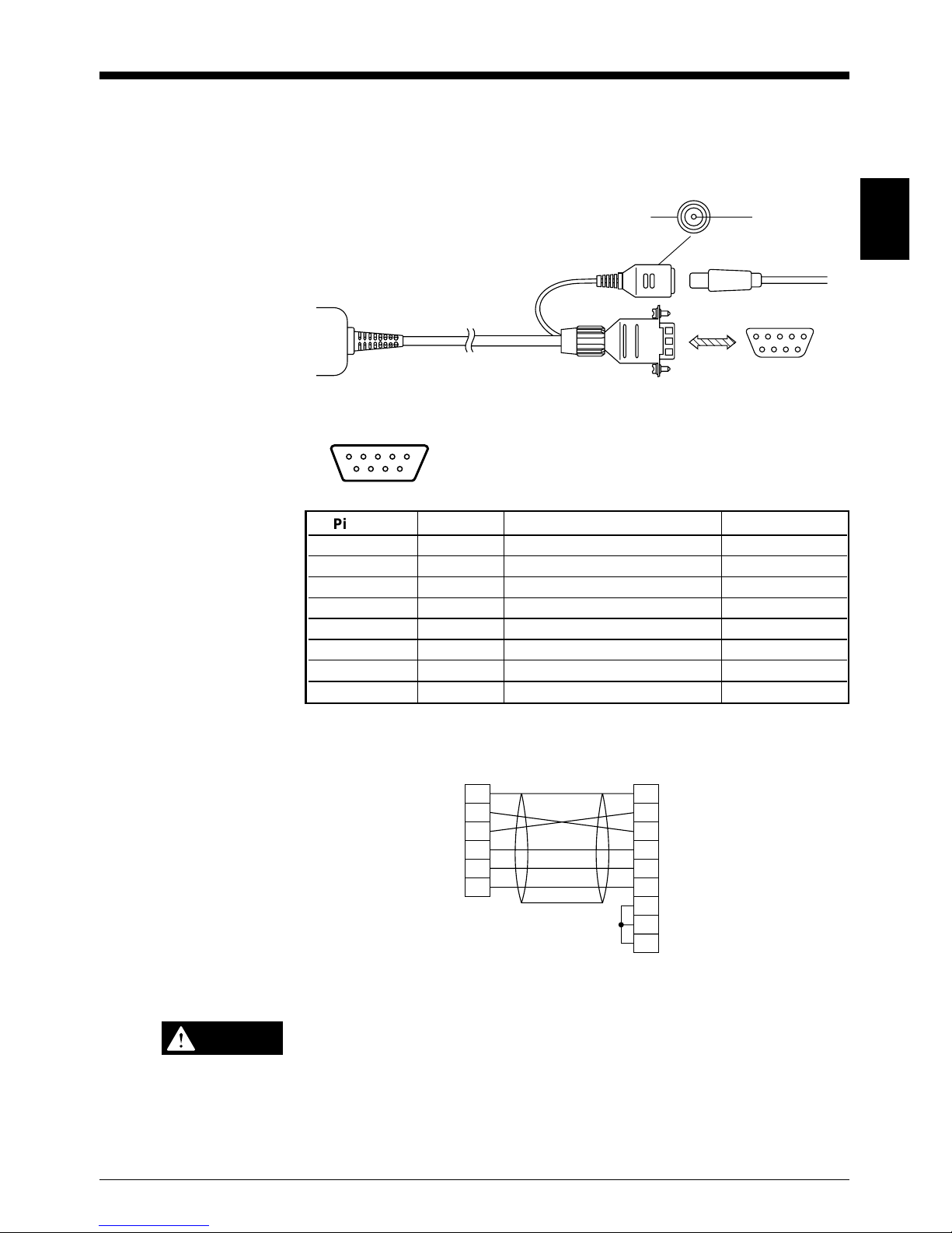
■ Connecting the BL-80RE
The BL-80RE can be connected directly to the RS-232C port (D-sub 9-pin
connector) of the DOS computer.
Use the supplied AC adapter to supply power to the BL-80RE.
Pin assignment
BL-80RE
D-sub 9-pin (female)
#4-40 screw
Prepare the cable shown below to connect the BL-80RE to a KEYENCE
product such as the KV-L2.
• Be sure to use the AC adapter included with the BL-80RE. Using
other AC adapters may cause product damage.
• Be sure to supply 120 VAC±10% to the AC adapter. Using other
power supply types may cause product damage.
5432
9876
1
GND
+5V
BL-80RE
AC adapter
DOS computer
(D-sub 9-pin)
Pin No. Symbol Function Signal direction
Connector case FG Frame Ground —
2 SD (TXD) Sends data Output
3 RD (RXD) Receives data Input
4 DR (DSR) Connects internally to pin No.6 Input
5 SG Signal Ground —
6 ER (DTR) Connects internally to pin No.4 Output
7 CS (CTS) Ready to send data Input
8 RS (RTS) Request to send data Output
Connector case
D-sub 9-pin (male)
#4-40 male screw
D-sub 25-pin (male)
M2.5 male screw
2
–
3
7
8
5
SD
RD
CS
RS
SG
SD
FG
RD
RS
SG
DR
CS
CD
ER
1
2
3
4
5
7
6
8
20
BL-80RE
KV-L2
CAUTION
Chapter 1 Overview
1
6
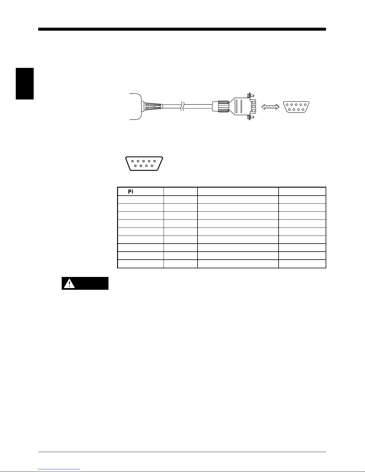
■ Connecting the BL-80RKE
The BL-80RKE can be connected directly to a KEYENCE product such as
the BL-V35E/BL Series power supply unit such as the BL-U1, BL-U2 and
N-42. Connect the BL-80RKE to a KEYENCE product as shown below.
Pin assignment
BL-80RKE
D-sub 9-pin (female)
#4-40 screw
KEYENCE product
(D-sub 9-pin)
BL-80RKE
5432
9876
1
Pin No. Symbol Function Signal direction
Connector case FG Frame Ground —
2 RD (RXD) Receives data Input
3 SD (TXD) Sends data Output
4 ER (DTR) Connects internally to pin No.6 Output
5 SG Signal Ground —
6 DR (DSR) Connects internally to pin No.4 Input
7 RS (RTS) Request to send data Output
8 CS (CTS) Ready to send data Input
9 +5V +5V power supply Input
Be sure to supply 5 VDC±5% to pin No.9 (+5V). Using other power
supply types may cause product damage.
CAUTION

Chapter 2
Operation
2.1 Reading Operation ........................................................8
2.2 Double-reading Prevention Function ..........................8
2.3 Trigger Switch Operation ..............................................8
2.4 Data Format ....................................................................9
2.5 Settings for Keyboard Interface ................................11
2.6 Communication Protocol [For RS-232C type only] ..12

Chapter 2 Operation
2
8
2.1 Reading Operation
Press the trigger switch to turn on the BL-80 Series’ light source LED.
Then, hold a bar code to the read window while the LED is illuminated.
The BL-80 Series automatically reads the bar code and sends the readout
data to the host computer. Several bar codes can be read while the light
source LED is illuminated. There are 5 modes of trigger operation that can
be selected in the setup menu.
Note: Be sure to hold only one bar code to the read window at a time. If
two or more bar codes are held to the read window simultaneously, the
BL-80 Series may continue reading each bar code repeatedly.
2.2 Double-reading Prevention Function
When a bar code is held to the read window for some time, the doublereading prevention function is activated to prevent the same bar code
from being read two or more times (the double-reading prevention period
is 0.3 sec.). Therefore, to read a bar code immediately after reading
another bar code with the same information, you need to cancel the
double-reading prevention function. This is done by turning off the light
source LED once, or by removing the bar code from the read window for
more than 1 second.
2.3 Trigger Switch Operation
The following 5 trigger operation modes can be selected according to the
application.
■ Auto-off mode 1
When the trigger switch is pressed, the light source LED illuminates.
The light source LED turns off when:
• the bar code has been read and then the readout data has been sent.
• 5 minutes have elapsed since the trigger switch has been released.
■ Auto-off mode 2
When the trigger switch is pressed, the light source LED illuminates.
The light source LED turns off when:
• 5 minutes have elapsed since the trigger switch has been released.
• 5 minutes have elapsed since the last bar code has been read.
This means that even releasing the trigger switch will not cause the light
source LED to switch off if bar codes are read at intervals of less than 5
minutes.
Chapter 2 Operation
9
2
■ Momentary switch mode
The light source LED illuminates while the trigger switch is held down. The
LED turns off when the switch is turned released.
■ Alternate switch mode
The light source LED toggles on and off each time the trigger switch is
pressed.
■ Continuous reading mode
The light source LED illuminates continuously.
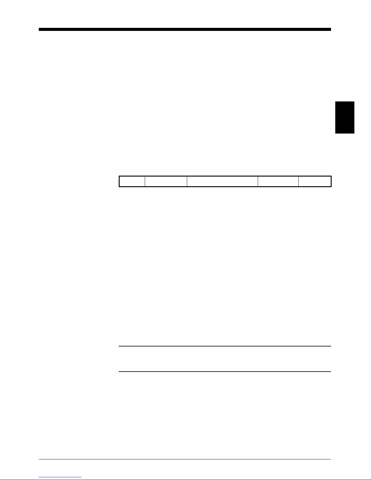
2.4 Data Format
The readout data is sent to the host computer in the following format.
Data format has been factory set before shipping:
Header: Not given
Bar code type: Not added
Number of bar code digits: Not added
Terminator: [CR]
1. Header
One character can be added to indicate the beginning of a data. You
can select a header from the following characters, according to the BL80 Series’ interface type.
• Keyboard interface type [BL-80V(N)E]
You can select a header from [HT], [ESC], [ ], [➞], [ ] and [ ]. The
[ ], [➞], [ ] and [ ] correspond to the cursor keys of the personal
computer. You can also set any desired character. You do not have to
use a header.
Note: When you set a desired character, do not use any other ASCII
control codes (01h to 2Fh in ASCII) than listed above and [BS] to set a
header.
• RS-232C type [(BL-80R(K)E]
You can select a header from [STX] and [ESC]. You can also set any
desired character. You do not have to use a header.
Header Bar code type Number of bar code digits Readout data Terminator
1
2
3
4
5
➞
➞
➞
➞
➞
➞
Chapter 2 Operation
2
10
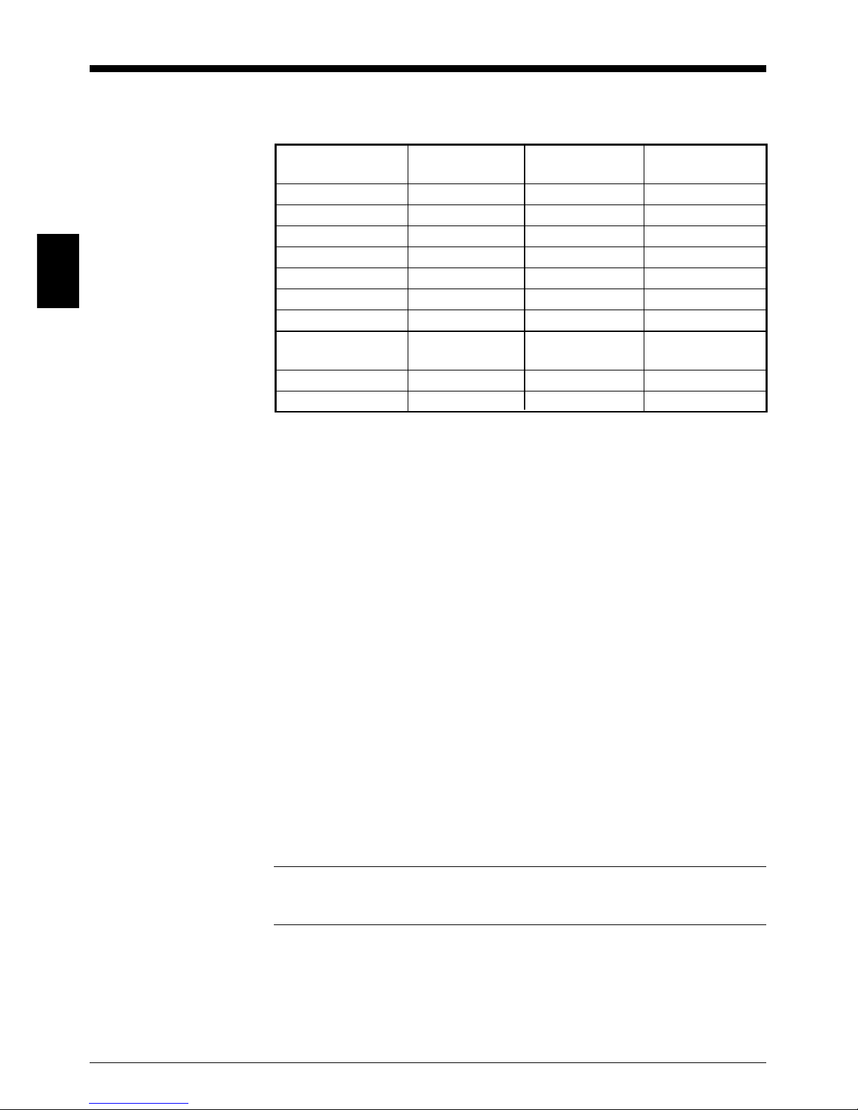
2. Bar code type
An identification code can be added to indicate the read bar code type.
Bar code type Identification Identification Identification
code A code B code C
JAN/EAN-13 F 4 E
JAN/EAN-8 FF 4 E
UPC-A A 4 E
UPC-E E 4 E
CODABAR N 3 F
CODE39 M 0 A
ITF I 1 I
Industrial 2 of 5, H 2 S
IATA
CODE93 L 8 G
CODE128 K 5 C
* Identification code B denotes the factory settings.
3. Number of bar code digits
The readout bar code digits is sent in 2 digits. The number is always 2
digits. If the bar code is 1 digit, a zero (0) is added before the readout
bar code.
However, if the bar code type is JAN, EAN or UPC, this number is not
added.
4. Readout data
The read bar code data is sent. If reading failed, no data is sent.
5. Terminator
One or two characters can be added to indicate the end of the readout
data. You can select a terminator from the following character, according to the BL-80 Series’ interface type.
• Keyboard interface type [BL-80V(N)E]
You can select a terminator from [HT], [CR], [ ], [➞], [ ] and [ ]. The
[ ], [➞], [ ] and [ ] correspond to the cursor keys of personal
computers. You can also select any desired one or two characters. You
do not have to use a terminator.
Note: When you set a desired character, do not use any other ASCII
control codes (01h to 2Fh in ASCII) than listed above and [BS] to set a
terminator.
• RS-232C type [BL-80R(K)E]
You can select a terminator from [ETX], [CR], [LF], [EOT] and [CR][LF].
You can also select any desired one or two characters.
➞
➞
➞
➞
➞
➞

Chapter 2 Operation
11
2
2.5 Settings for Keyboard Interface
■ Inter-character delay
You can set a transmission interval between characters to be sent from
the bar code reader to the personal computer. There are 9 different
intervals available. If the personal computer’s processing speed is slow, it
can not receive all of the data. This can be prevented by setting a longer
interval for accurate data reception.
■ Country setting
The BL-80V(N)E complies with the following national language keyboard
types.
• USA
• INTERNATIONAL
• JAPANESE
The factory setting is USA.
■ CAPS setting
Set the CAPS status of the keyboard input when using the BL-80V(N)E.
When the INTERNATIONAL is set in the country setting, the CAPS setting
is ignored.
• When BL-80 is set to CAPS-ON
When the personal computer’s CAPS is set to ON, the readout bar code
data is expressed in the same characters as the keyboard input. For
example, when the character input from the keyboard is typed in
uppercase, the readout bar code data is expressed in uppercase and
vice versa.
When the personal computer’s CAPS is set to OFF, the readout
barcode is expressed in the uppercase/lowercase style different from
the keyboard input.
• When BL-80 is set to CAPS-OFF
When the personal computer’s CAPS is set to OFF, the readout bar
code data is expressed in the same characters as the keyboard input.
When the personal computer’s CAPS is set to ON, the readout bar code
data is expressed in the uppercase/lowercase style different from the
keyboard input.
 Loading...