


HF TRANSCEIVER
TS-870S
Intelligent Digital Enhanced Communications System
INSTRUCTION MANUAL
KENWOOD CORPORATION
© B62-1536-00 (K,P,E,X,M)(MC) 09 08 07 06 05 04 03 02 01 00

APPLICABLE MODEL
This manual applies to the following model:
TS-870S: HF Transceiver
Intelligent Digital Enhanced Communications System
WRITING CONVENTIONS FOLLOWED
The writing conventions described below have been followed to simplify instructions and avoid unnecessary repetition. This format is less confusing for the reader. Reviewing the following information now will reduce your learning period. That means less time will be spent reading this manual; more time will be available for operating.
Furthermore, a system of advisories is used as follows:
CAUTION: Possibility of equipment damage
Note: Important information or operating tip
Instruction |
|
|
What to do |
||
|
|
|
|
|
|
Press [KEY]. |
Press and release KEY. |
||||
|
|
|
|
|
|
Press |
Press and hold KEY1 down, |
||||
[KEY1]+[KEY2]. |
then press KEY2. If there are |
||||
|
|
|
more than two keys, press and |
||
|
|
|
hold down each key in turn |
||
|
|
|
until the final key has been |
||
|
|
|
pressed. |
||
|
|
|
|
|
|
Press |
Press KEY1 momentarily, |
||||
[KEY1], [KEY2]. |
release KEY1, then press |
||||
|
|
|
KEY2. |
||
Press |
With the transceiver power |
||||
[KEY]+[ |
|
]. |
OFF, press and hold KEY, |
||
|
|||||
|
|||||
|
|
|
then switch ON the transceiver |
||
|
|
|
power by pressing |
||
|
|
|
[ |
|
] (POWER). |
|
|
|
|
||
|
|
|
|
||
|
|
|
|
|
|
Note: Basic procedures are numbered sequentially to guide you step-by-step. Additional information pertaining to a step, but not essential to complete the procedure, is provided in bulleted form following many steps for further guidance.
NOTICE TO THE USER
One or more of the following statements may be applicable to this equipment.
FCC WARNING
This equipment generates or uses radio frequency energy.
Changes or modifications to this equipment may cause harmful interference unless the modifications are expressly approved in the instruction manual. The user could lose the authority to operate this equipment if an unauthorized change or modification is made.
INFORMATION TO THE DIGITAL DEVICE USER REQUIRED BY THE FCC
This equipment has been tested and found to comply with the limits for a Class B digital device, pursuant to Part 15 of the FCC Rules. These limits are designed to provide reasonable protection against harmful interference in a residential installation.
This equipment generates, uses and can generate radio frequency energy and, if not installed and used in accordance with the instructions, may cause harmful interference to radio communications. However, there is no guarantee that the interference will not occur in a particular installation. If this equipment does cause harmful interference to radio or television reception, which can be determined by turning the equipment off and on, the user is encouraged to try to correct the interference by one or more of the following measures:
•Reorient or relocate the receiving antenna.
•Increase the separation between the equipment and receiver.
•Connect the equipment to an outlet on a circuit different from that to which the receiver is connected.
•Consult the dealer for technical assistance.
PRECAUTIONS
Please read all safety and operating instructions before using this transceiver. For best results, be aware of all warnings on the transceiver and follow the provided operating instructions. Retain these safety and operating instructions for future reference.
1Power Sources
Connect this transceiver only to the power source described in the operating instructions or as marked on the transceiver itself.
2Power Cable Protection
Route all power cables safely. Ensure the power cables can neither be walked upon nor pinched by items placed near or against the cables. Pay particular attention to locations near AC receptacles, AC extension bars and points of entry to the transceiver.
3Electrical Shocks
Take care not to drop objects or spill liquids into the transceiver through enclosure openings. Metal objects, such as hairpins or needles, inserted into the transceiver may contact voltages resulting in serious electrical shocks. Never permit children to insert any objects into this transceiver.
4Grounding and Polarization
Do not attempt to defeat methods used for grounding and electrical polarization in the transceiver, particularly involving the input power cable.
5Outdoor Antenna Grounding
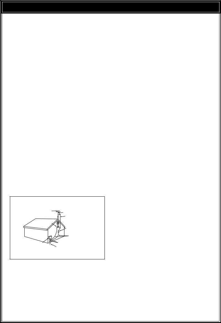
Adequately ground all outdoor antennas used with this transceiver using approved methods. Grounding helps protect against voltage surges caused by lightning. It also reduces the chance of a build-up of static charges.
EXAMPLE OF ANTENNA GROUNDING |
||
|
ANTENNA |
|
|
LEAD IN |
|
GROUND |
WIRE |
|
CLAMP |
ANTENNA |
|
|
||
|
DISCHARGE UNIT |
|
|
GROUNDING |
|
|
CONDUCTORS |
|
ELECTRIC SERVICE |
GROUND CLAMPS |
|
POWER SERVICE GROUNDING |
||
EQUIPMENT |
||
|
ELECTRODE SYSTEM |
|
6Power Lines
Minimum recommended distance for an outdoor antenna from power lines is one and one-half times the vertical height of the associated antenna support structure. This distance allows adequate clearance from the power lines if the support structure should fail for any reason.
7Ventilation
Locate the transceiver so as not to interfere with its ventilation. Do not place books or other equipment on the transceiver that may impede the free movement of air. Allow a minimum of 4 inches
(10 cm) between the rear of the transceiver and the wall or operating desk shelf.
8Water and Moisture
Do not use the transceiver near water or sources of moisture. For example, avoid use near bathtubs, sinks, swimming pools, and in damp basements and attics.
9Abnormal Odors
The presence of an unusual odor or smoke is often a sign of trouble. Immediately turn the power OFF and remove the power cable. Contact a dealer or the nearest Service Center for advice.
10Heat
Locate the transceiver away from heat sources such as radiators, stoves, amplifiers or other devices that produce substantial amounts of heat.
11Cleaning
Do not use volatile solvents such as alcohol, paint thinner, gasoline or benzene to clean the cabinet. Use a clean cloth with warm water or a mild detergent.
12Periods of Inactivity
Disconnect the input power cable from the power source when the transceiver is not used for long periods of time.
13Servicing
Remove the transceiver’s enclosure only to do accessory installations described by this manual or accessory manuals. Follow provided instructions carefully to avoid electrical shocks. If unfamiliar with this type of work, seek assistance from an experienced individual, or have a professional technician do the task.
14Damage Requiring Service
Enlist the services of qualified personnel in the following cases:
a)The power supply or plug is damaged.
b)Objects have fallen or liquid has spilled into the transceiver.
c)The transceiver has been exposed to rain.
d)The transceiver is operating abnormally or performance has degraded seriously.
e)The transceiver has been dropped or the enclosure damaged.
i

CONTENTS
APPLICABLE MODEL .................. |
Inside Front Cover |
||
WRITING CONVENTIONS |
|
|
|
FOLLOWED ................................. |
|
Inside Front Cover |
|
NOTICE TO THE USER ............... |
Inside Front Cover |
||
PRECAUTIONS |
|
|
i |
CONTENTS |
|
|
ii |
CHAPTER 1 |
INTRODUCTION |
|
1 |
THANK YOU! ........................................................... |
|
|
1 |
DSP — MAXIMUM SIGNAL/ MINIMUM NOISE |
....... 1 |
||
FEATURES.............................................................. |
|
|
1 |
SUPPLIED ACCESSORIES .................................... |
|
1 |
|
CHAPTER 2 |
INSTALLATION |
|
2 |
ANTENNA CONNECTION ....................................... |
|
2 |
|
GROUND CONNECTION ........................................ |
|
3 |
|
LIGHTNING PROTECTION ..................................... |
|
3 |
|
DC POWER SUPPLY CONNECTION...................... |
3 |
||
REPLACING FUSES ........................................... |
|
3 |
|
ACCESSORY CONNECTIONS ............................... |
|
4 |
|
FRONT PANEL .................................................... |
|
4 |
|
Headphones (PHONES) ................................. |
|
4 |
|
Microphone (MIC) ........................................... |
|
4 |
|
REAR PANEL ...................................................... |
|
4 |
|
External Speaker (EXT SP) ............................ |
|
4 |
|
Keys and Keyboards for CW Operation |
|
||
(PADDLE and KEY) ........................................ |
|
4 |
|
Computer Interface (COM).............................. |
|
5 |
|
RTTY Equipment (RTTY and ACC 2) .............. |
5 |
||
Linear Amplifier (REMOTE) ............................. |
|
5 |
|
Antenna Tuner (AT) ........................................ |
|
6 |
|
SM-230 Station Monitor (IF OUT 1) ................. |
6 |
||
Accessory Equipment (ACC 2) ....................... |
6 |
||
CHAPTER 3 |
GETTING ACQUAINTED |
|
8 |
YOUR FIRST QSO .................................................. |
|
8 |
|
RECEIVING ......................................................... |
|
8 |
|
TRANSMITTING .................................................. |
|
9 |
|
FRONT PANEL ...................................................... |
|
10 |
|
MICROPHONE ...................................................... |
|
14 |
|
REAR PANEL |
........................................................ |
|
15 |
DISPLAY ............................................................... |
|
|
16 |
CHAPTER 4 |
OPERATING BASICS |
|
19 |
SWITCHING POWER ON/OFF ............................. |
|
19 |
|
ADJUSTING VOLUME .......................................... |
|
19 |
|
AUDIO FREQUENCY (AF) GAIN....................... |
19 |
||
RADIO FREQUENCY (RF) GAIN ...................... |
19 |
||
ADJUSTING SQUELCH ........................................ |
|
19 |
|
DUAL DIGITAL VFOs ............................................ |
19 |
|
SELECTING VFOS ([RX A], [RX B]) .................. |
19 |
|
EQUALIZING VFO FREQUENCIES ([A=B]) ...... |
20 |
|
SELECTING MODE ............................................... |
20 |
|
SELECTING FREQUENCY ................................... |
20 |
|
CHANGING BANDS .......................................... |
20 |
|
USING 1 MHz STEPS ....................................... |
20 |
|
QUICK CHANGES ............................................ |
21 |
|
Changing Step Sizes .................................... |
21 |
|
FINE TUNING .................................................... |
21 |
|
DIRECT FREQUENCY ENTRY ......................... |
22 |
|
FRONT PANEL METER ........................................ |
22 |
|
TRANSMITTING .................................................... |
23 |
|
SELECTING TRANSMIT POWER ..................... |
23 |
|
TRANSMIT CARRIER LEVEL ........................... |
23 |
|
MICROPHONE GAIN ........................................ |
23 |
|
CHAPTER 5 |
MENU SETUP |
24 |
WHAT IS A MENU? ............................................... |
24 |
|
MENU ACCESS .................................................... |
24 |
|
MENU A/ MENU B ............................................. |
24 |
|
QUICK MENU FUNCTION ................................ |
24 |
|
Programming the Quick Menu ...................... |
24 |
|
Using the Quick Menu................................... |
24 |
|
TEMPORARY MENU RESETTING ....................... |
24 |
|
MENU CONFIGURATION ..................................... |
25 |
|
CROSS REFERENCE FOR |
|
|
MENU FUNCTIONS .............................................. |
28 |
|
CHAPTER 6 |
COMMUNICATING |
29 |
SSB TRANSMISSION ........................................... |
29 |
|
SLOW SCAN TV/ FACSIMILE ........................... |
29 |
|
CW TRANSMISSION ............................................ |
30 |
|
TX SIDETONE/ RX PITCH FREQUENCY ......... |
30 |
|
ZERO-BEATING ................................................ |
30 |
|
SWITCHING TX/RX MANUALLY ....................... |
30 |
|
SEMI BREAK-IN ................................................ |
31 |
|
Setting Delay Time ........................................ |
31 |
|
FULL BREAK-IN ................................................ |
31 |
|
CW REVERSE (RECEIVE) ................................ |
31 |
|
RISE/DECAY TIMES ......................................... |
31 |
|
ELECTRONIC KEYER ...................................... |
32 |
|
Learning Outline ........................................... |
32 |
|
Multiple-Button Functions .............................. |
33 |
|
Emulation Options ........................................ |
33 |
|
Storing CW Messages .................................. |
34 |
|
CW Message Playback ................................. |
34 |
|
Erasing CW Messages ................................. |
35 |
|
Inquiry Functions .......................................... |
35 |
|
Function Commands ..................................... |
36 |
|
Embedded Functions .................................... |
37 |
|
Serial Number Options .................................. |
37 |
|
ii

FM TRANSMISSION ............................................. |
38 |
|
FM REPEATER OPERATION ............................ |
38 |
|
Selecting Subtone Frequency ....................... |
39 |
|
Continuous or Burst Subtones? .................... |
39 |
|
AM TRANSMISSION ............................................. |
40 |
|
DIGITAL OPERATION ........................................... |
40 |
|
RTTY (FREQUENCY SHIFT KEYING) .............. |
40 |
|
ERROR-CHECKING MODES (AMTOR/ PACKET/ |
||
PACTOR/ G-TOR/ CLOVER .............................. |
41 |
|
SPLIT-FREQUENCY OPERATION ........................ |
42 |
|
TF-SET (TRANSMIT FREQUENCY SET) .......... |
43 |
|
SATELLITE OPERATION .................................. |
43 |
|
CHAPTER 7 |
OPERATING AIDS |
44 |
RECEIVING |
........................................................... |
44 |
RIT (RECEIVE .........INCREMENTAL TUNING) |
44 |
|
AGC (AUTOMATIC ...............GAIN CONTROL) |
44 |
|
Changing .............................................AGC |
44 |
|
Changing ........................................AF AGC |
44 |
|
TRANSMITTING .................................................... |
45 |
|
VOX (VOICE .............-OPERATED TRANSMIT) |
45 |
|
Microphone ..............Input Level Adjustment |
45 |
|
Delay Time .................................Adjustment |
45 |
|
TRANSMIT ...........................................INHIBIT |
45 |
|
XIT (TRANSMIT .......INCREMENTAL TUNING) |
45 |
|
SPEECH ....................PROCESSOR (SSB/AM) |
46 |
|
CHANGING FREQUENCY WHILE |
|
|
TRANSMITTING ................................................ |
46 |
|
TRANSMIT ......................................MONITOR |
46 |
|
CUSTOMIZING TRANSMIT SIGNAL |
|
|
CHARACTERISTICS ........................(SSB/AM) |
47 |
|
Changing ......................Transmit Bandwidth |
47 |
|
Transmit ........................................Bandshift |
47 |
|
Equalizing .............................Transmit Audio |
47 |
|
Microphone ..........................................AGC |
47 |
|
AUTOMATIC ..............................................MODE |
48 |
|
AUTOMATIC ..................MODE BOUNDARIES |
48 |
|
USING AUTOMATIC ..............................MODE |
48 |
|
AUTOMATIC ...........................ANTENNA TUNER |
49 |
|
PRESETTING ........(INTERNAL TUNER ONLY) |
49 |
|
INTERNAL ............................................TUNER |
49 |
|
AT-300 EXTERNAL .........TUNER (OPTIONAL) |
50 |
|
COMPUTER ...[\ TRANSCEIVER INTERFACE |
50 |
|
COMMUNICATION ...................PARAMETERS |
50 |
|
CHAPTER 8 |
REJECTING INTERFERENCE |
51 |
DSP TOOLS |
.......................................................... |
51 |
SLOPE TUNING ...............................(SSB/AM) |
51 |
|
IF SHIFT (CW) ................................................... |
51 |
|
CHANGING RECEIVE BANDWIDTH |
|
|
(CW/FSK/FM) .................................................... |
52 |
|
ADAPTIVE .........................................FILTERS |
52 |
|
AUTO NOTCH ........................................(SSB) |
52 |
|
BEAT CANCEL .................................(SSB/AM) |
52 |
|
NOISE REDUCTION ..........(SSB/CW/FSK/AM) |
53 |
|
SETTING .......................................SPAC TIME |
53 |
|
NOISE BLANKER .................................................. |
53 |
|
AIP (ADVANCED .................INTERCEPT POINT) |
53 |
|
ATTENUATOR ....................................................... |
53 |
|
CHAPTER 9 |
MEMORY FEATURES |
54 |
MICROPROCESSOR ............MEMORY BACKUP |
54 |
|
CONVENTIONAL .............OR QUICK MEMORY? |
54 |
|
CONVENTIONAL ..................................MEMORY |
54 |
|
MEMORY ...............................CHANNEL DATA |
54 |
|
MEMORY ......................CHANNEL STORAGE |
54 |
|
Simplex .........................................Channels |
54 |
|
Split-Frequency .............................Channels |
55 |
|
MEMORY ..........................CHANNEL RECALL |
55 |
|
Quick Channel ..................................Search |
55 |
|
Temporary ....................Frequency Changes |
56 |
|
MEMORY .........................CHANNEL SCROLL |
56 |
|
MEMORY ......................................TRANSFER |
56 |
|
Memory ...........................\ VFO Transfers |
56 |
|
Channel .......................to Channel Transfers |
57 |
|
ERASING .....................MEMORY CHANNELS |
57 |
|
Full Reset ..................................................... |
57 |
|
STORING ....................SCAN LIMITS IN CH 99 |
58 |
|
Confirming ................Start/End Frequencies |
58 |
|
Programmable .......................VFO Function |
58 |
|
QUICK MEMORY .................................................. |
59 |
|
STORING ....................INTO QUICK MEMORY |
59 |
|
RECALLING ..............FROM QUICK MEMORY |
59 |
|
TEMPORARY ..........FREQUENCY CHANGES |
59 |
|
QUICK MEMORY .................................\ VFO |
59 |
|
CHAPTER 10 |
SCAN |
60 |
PROGRAM SCAN ................................................. |
60 |
|
SCAN HOLD ..................................................... |
60 |
|
CONFIRMING ...................START/END LIMITS |
60 |
|
MEMORY SCAN ................................................... |
61 |
|
BUSY FREQUENCY ...............................STOP |
61 |
|
Scan Resume ................................Methods |
61 |
|
ALL-CHANNEL .......................................SCAN |
61 |
|
GROUP SCAN .................................................. |
62 |
|
MEMORY ......................CHANNEL LOCKOUT |
62 |
|
SETTING SCAN .......................................SPEED |
62 |
|
iii

CHAPTER 11 |
OPERATOR CONVENIENCES |
63 |
MICROPROCESSOR RESET ............................... |
63 |
|
INITIAL SETTINGS ............................................ |
63 |
|
PARTIAL RESET ............................................... |
63 |
|
FULL RESET ..................................................... |
63 |
|
SWITCHING ANT 1/ ANT 2 .................................... |
63 |
|
PROGRAMMABLE FUNCTION BUTTONS ........... |
63 |
|
ASSIGNING FUNCTIONS ................................. |
64 |
|
USING THE PROGRAMMED BUTTONS .......... |
64 |
|
LOCK FUNCTION ................................................. |
64 |
|
BEEP FUNCTION.................................................. |
64 |
|
BUTTON CONFIRMATION ................................ |
65 |
|
ALARM NOTIFICATION .................................... |
65 |
|
DISPLAY DIMMER ................................................ |
65 |
|
QUICK DATA TRANSFER ..................................... |
65 |
|
SETTING UP ..................................................... |
65 |
|
Equipment Needed ....................................... |
65 |
|
Connections ................................................. |
66 |
|
USING QUICK TRANSFER ............................... |
66 |
|
Transferring Data .......................................... |
66 |
|
Receiving Data ............................................. |
66 |
|
DRU-3 DIGITAL RECORDING SYSTEM |
|
|
(OPTIONAL) .......................................................... |
|
67 |
RECORDING MESSAGES ................................ |
67 |
|
MESSAGE PLAYBACK ..................................... |
67 |
|
Checking Messages ..................................... |
67 |
|
Transmitting Messages (VOX) ...................... |
67 |
|
Transmitting Messages (Manual TX/RX) ....... |
68 |
|
CONTINUOUS MULTI-CHANNEL |
|
|
PLAYBACK |
........................................................ |
68 |
ALTERING INTER-MESSAGE INTERVAL ......... |
68 |
|
VS-2 VOICE SYNTHESIZER (OPTIONAL) ............ |
68 |
|
CHAPTER 12 |
MAINTENANCE |
69 |
GENERAL INFORMATION .................................... |
69 |
|
SERVICE ............................................................... |
|
69 |
SERVICE NOTE .................................................... |
69 |
|
CLEANING ............................................................ |
|
69 |
INTERNAL ADJUSTMENTS .................................. |
70 |
|
REFERENCE FREQUENCY CALIBRATION ..... |
70 |
|
DRU-3 DIGITAL RECORDING UNIT |
|
|
(OPTIONAL) ...................................................... |
70 |
|
AT-300 EXTERNAL TUNER (OPTIONAL) ......... |
70 |
|
TROUBLESHOOTING ........................................... |
71 |
|
CHAPTER 13 |
OPTIONAL ACCESSORIES |
74 |
CHAPTER 14 |
INSTALLING OPTIONS |
75 |
REMOVING THE CASE ........................................ |
75 |
|
TOP CASE |
........................................................ |
75 |
BOTTOM CASE ................................................ |
75 |
|
DRU-3 DIGITAL RECORDING UNIT ..................... |
75 |
|
VS-2 VOICE SYNTHESIZER UNIT ........................ |
75 |
SO-2 TEMPERATURE-COMPENSATED |
|
CRYSTAL OSCILLATOR (TCXO) .......................... |
76 |
SPECIFICATIONS |
77 |
APPENDICES |
79 |
APPENDIX A: LEARNING ABOUT DSP ............... |
79 |
APPENDIX B: PROPAGATION INFORMATION .... |
80 |
STANDARD TIME AND INFORMATION |
|
STATIONS ......................................................... |
80 |
NCDXF/IARU BEACON NETWORK .................. |
80 |
HF BEACONS ................................................... |
80 |
APPENDIX C: GENERAL COVERAGE RECEIVER |
|
FOR SWLING ........................................................ |
82 |
APPENDIX D: COM CONNECTOR |
|
PROTOCOL .......................................................... |
83 |
HARDWARE DESCRIPTION ............................. |
83 |
CONTROL OPERATION ................................... |
83 |
COMMANDS ..................................................... |
83 |
COMMAND DESCRIPTION .............................. |
83 |
PARAMETER DESCRIPTION ........................... |
84 |
TERMINATOR ................................................... |
85 |
TYPES OF COMMANDS ................................... |
85 |
COMPUTER CONTROL COMMANDS .............. |
85 |
ERROR MESSAGES......................................... |
86 |
COMMAND USE PRECAUTIONS ..................... |
86 |
MENU SELECTION TABLE FOR |
|
“EX” COMMAND, PARAMETER 36 ................... |
87 |
READING COMMAND TABLES ........................ |
89 |
COMMAND TABLES ......................................... |
89 |
INDEX |
96 |
iv

INTRODUCTION
THANK YOU!
The TS-870S Intelligent Digital Enhanced Communications System was developed by a team of engineers determined to continue the tradition of excellence and innovation in KENWOOD HF transceivers.
Taking maximum advantage of Digital Signal Processing technology, the TS-870S introduces operating tools like Auto Notch, Beat Cancel, and Noise Reducer. When coupled with its IF Shift, Noise Blanker, and Advanced Intercept Point functions, you will enjoy a critical edge as you fight QRM and QRN in the new solar cycle. In addition, the convenience of a built-in RS-232C connector can transport your shack into the world of remote transceiver control via computer.
But first, tame your ego and enthusiasm temporarily — read every page of this book. Consider this manual to be a personal tutorial from the designers; allow it to guide you through the learning process now, then act as a reference in the coming years. Though user friendly, the TS-870S is technically sophisticated and some features may be new to you. Your reward for your diligence will be mastery of the TS-870S in the shortest time possible with maximum fun.
As you continue exploring Amateur radio, thank you for allowing the KENWOOD family to join you in this chapter of your adventure.
DSP —
MAXIMUM SIGNAL/ MINIMUM NOISE
The TS-870S design includes a 2-channel Sigma-delta A/D converter, two 2-channel Sigma-delta D/A converters, and a 2-channel advanced single-bit D/A converter. Operating at a clock rate of 40 MHz, DSP works for you whether you use SSB, CW, FM, or any other mode. The adaptive filter functions include Auto Notch, Line Enhance, and Beat Cancel.
DSP is the most effective way of using current technology to separate what you want from what you don’t want. While receiving, you hear the most signal and the least noise. While transmitting, you emit only the desired audio components of the modulation without adding distortion. The transmit equalizer combines high boost, bass boost, and comb filter functions to further improve your signal.
With DSP, you will hear clear receive signals that are covered by noise on conventional equipment. The enhancement of the receive signal is due to the reduction of atmospheric and white noise, and to rejection of adjacent frequency interference including heterodynes. This capability of DSP to “clean up” the environment surrounding the desired signal has a significant effect. The signal you are trying to receive will seem stronger and clearer even though the S-meter reads the same. Those tired of listening to interference of all kinds while operating may think a little magic is being used.
FEATURES
•Employs Digital Signal Processing (DSP) techniques to significantly improve the quality of received and transmitted signals.
•Includes extensive user-adjustable digital and analog filtering functions for combating all forms of received interference.
•Allows total customization of transmitted audio through use of functions such as Transmit Equalizer.
•Introduces a built-in RS-232C port for directly interfacing to a computer. Supports computer control of functions at a user-selectable transfer rate between 1200 and 57600 bps inclusive.
•Streamlines function setup by presenting an intuitive Menu System for function configuration and control.
•Conveniently allows ANTENNA1/ANTENNA2 selection from the Front Panel.
•Directly addresses CW operators’ interests by including a full-function K-1 Logikey complete with test mode, semi-automatic mode, and popular keyer emulations. The Rear Panel is equipped with a PADDLE jack and a KEY jack for connecting a paddle, an external keyer, or a keyboard.
•Provides an antenna tuner that can easily be inserted into or removed from the transmit and receive paths.
SUPPLIED ACCESSORIES
Accessory |
Part Number |
Quantity |
Microphone |
T91-0352-XX |
1 |
|
|
|
DC power cable |
E30-3157-XX |
1 |
7-pin DIN plug |
E07-0751-XX |
1 |
13-pin DIN plug |
E07-1351-XX |
1 |
Fuse (25 A) |
F05-2531-XX |
1 |
Fuse (4 A) |
F06-4029-XX |
1 |
Spacer |
J02-0479-XX |
2 |
Screw |
N91-3016-XX |
2 |
Instruction manual |
B62-1536-XX |
1 |
Schematic/block diagrams1 |
B52-0606-XX |
1 |
Warranty card |
— |
1 |
(U.S.A., Canada, and |
||
Europe only) |
|
|
1 France, Holland: B52-0607-XX
You can effectively lengthen the front feet of the TS-870S. Remove the screws that fasten the front feet to the transceiver. As shown, install the supplied spacers and the front feet by using the supplied screws. The removed screws are not required, but save them in case you decide to remove the spacers in future.
These sides must face the TS-870S case.
Supplied spacer
Supplied screw
1
INSTALLATION
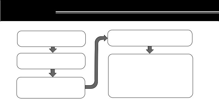
|nstall and connect an antenna system {page 2}.
Install a ground system that satisfies DC and RF grounding requirements {page 3}.
Install lightning protection to protect the antenna system, your personal safety, and your property {page 3}.
ANTENNA CONNECTION
The type of the antenna system, consisting of the antenna, ground, and feed line, will greatly affect the successful performance of the transceiver. Use a properly adjusted 50 Ω antenna of good quality to let your transceiver perform at its best. Use a good-quality 50 Ω coaxial cable and a first-quality connector for the connection. Match the impedance of the coaxial cable and antenna so that the SWR is 1.5:1 or less. All connections must be clean and tight.
While the transceiver’s protection circuit will activate if the SWR is greater than 2.5:1, do not rely on protection to compensate for a poorly functioning antenna system. High SWR will cause the transmit output to drop, and may lead to radio frequency interference to consumer products such as stereo receivers and televisions. You may even interfere with your own transceiver. Reports that your signal is garbled or distorted, especially at peak modulation, may indicate that your antenna system is not efficiently radiating the transceiver’s power. If you feel a tingle from the transceiver’s cabinet or the microphone’s metal fittings when you modulate, you can be certain that, at the least, your coax connector is loose at the rear of the radio and, at the worst, your antenna system is not efficiently radiating power.
Connect your antenna feed line to ANT 1. If you are using two antennas, connect the second antenna to ANT 2. The EXT RX ANT jack can be used to connect a separate receiver. Note that this jack must be enabled by Menu configuration {pages 24, 27} before it can be used.
CAUTION:
Transmitting without first connecting an antenna or other matched load may damage the transceiver. Always connect the antenna to the transceiver before transmitting.
Use a lightning arrestor to prevent fire, electric shock, or damage to the transceiver.
Install and connect a DC power supply {page 3}.
Connect all accessories to the transceiver {page 4}. Accessories include the following:
• Microphone |
• Headphones |
||
• |
Antenna Tuner |
• |
External Speaker |
• CW Key |
• RTTY Equipment |
||
• |
Computer |
• |
Linear Amplifier |
•TNC/ Multimode Communications Processor
APPROX. LOSS (dB) PER 30 METERS (100 FEET) OF CORRECTLY MATCHED 50 Ω LINE
•Use only as a general guide. Specifications may vary between cable manufacturers.
Transmission Line |
3.5 MHz |
14 MHz |
30 MHz |
|
|
|
|
RG-174, -174A |
2.3 |
4.3 |
6.4 |
|
|
|
|
RG-58A, -58C |
0.75 |
1.6 |
2.6 |
|
|
|
|
3D-2V |
0.80 |
1.5 |
2.3 |
|
|
|
|
RG-58, -58B |
0.65 |
1.5 |
2.3 |
|
|
|
|
RG-58 Foam |
0.70 |
1.4 |
2.1 |
|
|
|
|
RG-8X |
0.50 |
1.0 |
2.0 |
5D-2V |
0.45 |
0.93 |
1.4 |
|
|
|
|
RG-8, -8A, -9, -9A, 9B, |
0.38 |
0.80 |
1.2 |
-213, 214, 215 |
|
|
|
|
|
|
|
5D-FB |
N/A |
0.80 |
1.0 |
|
|
|
|
RG-8 Foam |
0.29 |
0.60 |
0.90 |
|
|
|
|
8D-2V |
0.29 |
0.60 |
0.90 |
|
|
|
|
10D-2V |
0.24 |
0.50 |
0.72 |
|
|
|
|
9913 |
0.24 |
0.48 |
0.70 |
|
|
|
|
8D-FB |
N/A |
0.48 |
0.68 |
|
|
|
|
10D-FB |
N/A |
0.37 |
0.54 |
|
|
|
|
12D-FB |
N/A |
0.33 |
0.45 |
|
|
|
|
RG-17, -17A |
0.13 |
0.29 |
0.48 |
|
|
|
|
1/2" Hardline |
0.12 |
0.26 |
0.40 |
|
|
|
|
20D-2V |
< 0.10 |
0.25 |
0.39 |
3/4" Hardline |
< 0.10 |
0.21 |
0.32 |
|
|
|
|
7/8" Hardline |
< 0.10 |
0.16 |
0.26 |
N/A: Not available |
|
|
|
2
2 INSTALLATION
GROUND CONNECTION
At the minimum, a good DC ground is required to prevent such dangers as electric shock. For superior communications results, a good RF ground is required, against which the antenna system can operate. Both of these conditions can be met by providing a good earth ground for your station. Bury one or more ground rods, or a large copper plate under the ground, and connect this to the transceiver GND terminal. Use heavy gauge wire or a copper strap, cut as short as possible, for this connection. Just as for antenna work, all connections must be clean and tight.
LIGHTNING PROTECTION
Consider carefully how to protect your equipment and your home from lightning. Even in areas where lightning storms are less common, there is usually a limited number of storms each year. Take the time to study the best way to protect your installation from the effects of lightning by consulting reference material on the subject.
The installation of a lightning arrestor is a start, but there is more that you can do. For example, terminate your antenna system transmission lines at an entry panel that you install outside your home. Ground this entry panel to a good outside ground, and then connect appropriate feed lines between the entry panel and your transceiver. When a lightning storm occurs, you can ensure added protection by disconnecting the feed lines from your transceiver.
CAUTION: DO NOT attempt to use a gas pipe (which is clearly dangerous), an electrical conduit (which has the whole house wiring attached and may act like an antenna), or a plastic water pipe for a ground.
DC POWER SUPPLY CONNECTION
In order to use this transceiver, you will need a separate 13.8 V DC power supply that must be purchased separately. DO NOT directly connect the transceiver to an AC outlet! Use the supplied DC power cable to connect the transceiver to a regulated power supply. Do not substitute a cable with smaller gauge wires. The current capacity of your power supply must be 20.5 A or more.
CAUTION:
Before connecting the DC power supply to the transceiver, be sure to switch the transceiver and the DC power supply OFF.
Do not plug the DC power supply into an AC outlet until you make all connections.
This transceiver has not been tested for use in mobile applications.
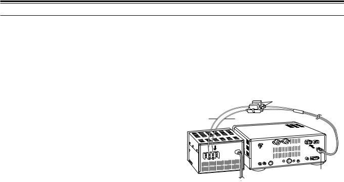
First connect the DC power cable to the regulated DC power supply and check that polarities are correct (Red: positive, Black: negative). Then connect the connectorized end of the DC power cable to the
DC 13.8 V power connector on the transceiver Rear Panel. Press the DC power cable connector firmly into the connector on the transceiver until the locking tab clicks.
Fuse holders
Black Red

 TS-870S DC 13.8 V DC power supply
REPLACING FUSES
If the fuse blows, determine the cause then correct the problem. After the problem is resolved, only then replace the fuse. If newly installed fuses continue to blow, disconnect the power plug and contact your dealer or nearest Service Center for assistance.
Fuse Location |
Fuse Current Rating |
|
|
|
|
TS-870S |
4 A |
|
(for AT-300 Tuner) |
||
|
||
|
|
|
Supplied Accessory |
25 A |
|
Cable |
||
|
||
|
|
CAUTION: Replace blown fuses only after investigating and correcting the cause of the failed fuse. Always replace a blown fuse by a new fuse with the specified ratings.
3
2 INSTALLATION
ACCESSORY CONNECTIONS
FRONT PANEL
■Headphones (PHONES)
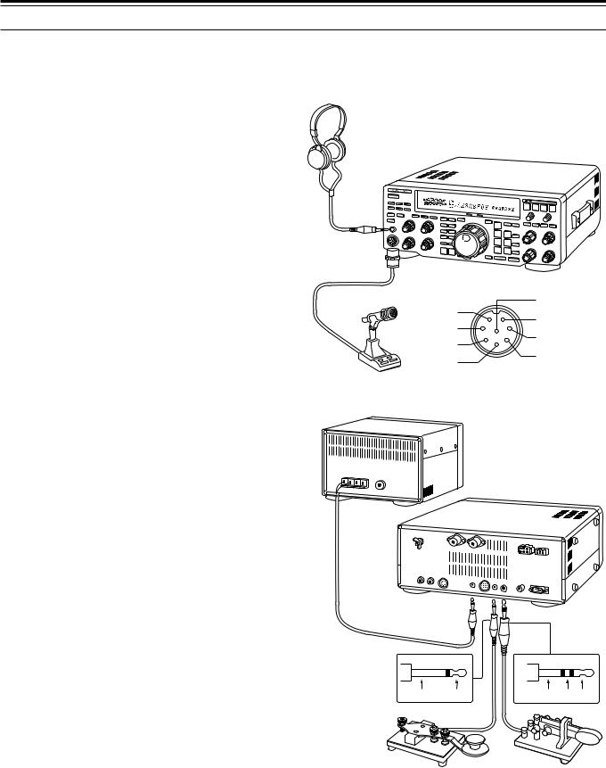
Use headphones having 4 to 32 Ω impedance. You can also use stereo headphones. When headphones are used, no sound is heard from the internal (or optional external) speaker. Use a 6.0 mm (1/4") diameter, 2-conductor (mono) or 3-conductor (stereo) plug.
■Microphone (MIC)
To communicate in the voice modes, connect to the MIC connector a microphone having an impedance between 250 Ω and 600 Ω. Insert the connector from your microphone fully, then screw the retaining ring clockwise until snug. Compatible microphones include the MC-43S, MC-60A, MC-80, MC-85, and MC-90. Do not use the MC-44, MC-44DM, MC-45, MC-45E, MC-45DM, or MC-45DME microphone.
REAR PANEL
■ External Speaker (EXT SP)
Ensure any external speaker used has an impedance of 8 Ω. Use a 3.5 mm (1/8") diameter, 2-conductor (mono) plug. When an external speaker is used, no sound is heard from the internal speaker.
WARNING! Do not connect headphones to this jack. The high audio output at this jack could damage your hearing.
■Keys and Keyboards for CW Operation (PADDLE and KEY)
For CW operation using the internal electronic keyer, connect a keyer paddle to the PADDLE jack. For CW operation without using the internal electronic keyer, connect a straight key, semi-automatic key (bug), electronic keyer, or the CW keyed output from a Multimode Communications Processor (MCP) to the KEY jack. The jacks mate with a 6.0 mm (1/4") 3-conductor plug and a 3.5 mm (1/8") 2-conductor plug respectively. External electronic keyers or MCPs must use positive keying to be compatible with this transceiver. Use a shielded cable between the key and the transceiver.
Note: Due to the full-featured functionality of the internal electronic keyer, you may decide it’s unnecessary to connect both a paddle and another type of key unless you specifically want to use a keyboard for CW. It’s recommended that you become familiar with the internal keyer by reading “ELECTRONIC KEYER” {page 32} before making your decision.
Headphones
S |
|
|
60 |
|
|
M.CH |
|
|
RIT |
XIT |
WIDTH SHIFT |
|
|
TS-870S |
|
MICq |
|
PTTw |
DOWNe |
|
|
UPr |
Microphone |
MIC connector |
External speaker
TS-870S
Ground +
iGND(STBY) uGND(MIC) yNC
t8 V(10 mA max)
(Front view)
Ground Dash Dot
Straight key |
Paddle |
Bug |
|
Electronic keyer |
|
MCP CW output |
|
4
2 INSTALLATION
■Computer Interface (COM)
This connector allows you to directly connect a computer or dumb terminal by using an RS-232C cable terminated with a female 9-pin connector. No external hardware interface is required between your computer and the transceiver if your computer has an unused RS-232C serial communications port. See Appendix D on page 83 for information relating to this connector.
RS-232C serial port
|
TS-870S |
Personal computer/ |
COM connector |
|
|
dumb terminal |
|
■RTTY Equipment (RTTY and ACC 2)
To operate Frequency Shift Keyed RTTY, connect your RTTY equipment as shown below. Connect the RTTY key output from your RTTY equipment to RTTY, and connect the demodulation input of your RTTY equipment to ACC 2, Pin 3. By default, a short condition generates a space; an open generates a mark. However, this can be reversed via Menu settings.
Do not share a single power supply between the transceiver and the RTTY equipment. Keep as wide a separation as possible between the transceiver and the RTTY equipment as practical to reduce noise-pickup by the transceiver.
MCP power supply
Demod input(RX)
|
MCP |
RTTY |
TS-870S |
|
|
key |
ACC 2 |
RTTY |
|
Personal computer/ |
|
|||
|
output |
|
|
|
dumb terminal |
|
|
|
|
|
(TX) |
|
|
|
|
|
|
|
■Linear Amplifier (REMOTE)
The REMOTE connector allows connection of an external transmit power amplifier. If using an amplifier, confirm that Menu No. 51 (LINEAR) is set to “1” (Fast) or “2” (Slow) {pages 24, 27}. This Menu item controls the linear amplifier TX/RX relay response time. Use the Fast setting unless you experience switching problems when using your amplifier for semi break-in operation.
Note: The TX/RX control method differs depending on external amplifier models. Some amplifiers enter the TX mode when the control terminal is grounded. For those amplifiers, connect pin 2 of the REMOTE connector to the GND terminal of the amplifier and connect pin 4 of the connector to the control terminal of the amplifier.
TS-870S |
Linear amplifier |
|
REMOTE connector |
|
|
|
|
Pin |
Function |
|
|
|
No. |
|
|
|
|
|
|
|
|
|
1 |
Speaker output |
|
Black |
|
2 |
Common terminal |
|
Red |
|
3 |
Standby; when grounded, the |
|
|
AC LINE |
||
|
|
|
transceiver enters TX mode. |
|
|
|
|
|
|
|
RF OUTPUT |
4 When connected with the common |
||
|
|
|
||
|
Control relay |
|
terminal, the amplifier enters TX mode. |
|
|
R |
|
5 When connected with the common |
|
|
T |
|
||
|
2 |
|
terminal, the amplifier enters RX mode. |
|
|
4 |
5 |
|
|
|
|
|
||
|
1 |
3 |
6 ALC input from amplifier |
|
|
6 |
7 |
||
|
GND |
|
7 |
Approx. +12 V DC is output when in |
|
REMOTE Connector |
|
TX mode (10 mA max.). |
|
|
|
|
||
|
(Rear Panel view) |
|
|
|
5
2INSTALLATION
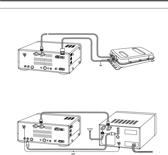
■Antenna Tuner (AT)
If using an external AT-300 antenna tuner, connect it here using the cable supplied with the antenna tuner. The AT-300 must be connected to ANT 1; it will not function if connected to ANT 2.
AT-300
TS-870S
■SM-230 Station Monitor (IF OUT 1)
Connect a cable from the IF OUT 1 jack to the IF IN jack on the SM-230 Station Monitor. This cable couples the 8.83 MHz IF from your TS-870S for pan display on the Station Monitor.
To Antenna
TS-870S |
SM-230 |
|
■Accessory Equipment (ACC 2)
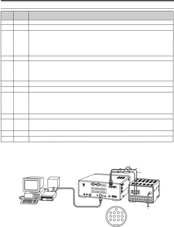
If you intend to use this transceiver for any of the digital modes, connect the input/output connections from a Terminal Node Controller (TNC) for Packet operation, a Multimode Communications Processor (MCP) for operation on Packet, PacTOR, AMTOR, G-TOR, or FAX, or a Clover interface to this connector.
SSTV and phone patch equipment can also be connected to ACC 2. SSTV operation is possible by connecting the input/output from a computer sound card to ACC 2, then running an SSTV application on the computer.
To operate on the digital modes, you will need the following equipment:
•Personal computer with communications software (alternatively, a “dumb” terminal capable of sending ASCII commands)
•TNC (Terminal Node Controller) or MCP (Multimode Communications Processor)
•TNC or MCP power supply
•RS-232C cable
•13-pin DIN plug and cable
Connect your TNC or MCP to the ACC 2 connector on the transceiver Rear Panel using a cable equipped with a 13-pin DIN plug.
Do not share a single power supply between the transceiver and the TNC or MCP. Keep as wide a separation between the transceiver and computer as practical to reduce noise-pickup by the transceiver. Refer to the accompanying table for connection information.
6
2 INSTALLATION
Pin No. Pin Name |
|
Function |
|
1 |
NC |
Not connected |
|
2 |
NC |
Not connected |
|
3 |
ANO |
Audio output from receiver |
|
|
|
• Connect to TNC or MCP receive data pin for digital operation. |
|
|
|
• Audio level is independent of AF gain control setting. |
|
|
|
• Audio level can be changed via Menu No. 21 (PKT.OUT) {page 25}. |
|
|
|
• Output impedance: 4.7 kΩ |
|
4 |
GND |
Shield for Pin 3 |
|
5 |
PSQ |
Squelch control |
|
|
|
• Connect to TNC or MCP squelch control pin for digital operation. |
|
|
|
• Prevents the TNC from transmitting while the receiver squelch is open. |
|
|
|
• Squelch open: Low impedance |
• Squelch closed: High impedance |
6 |
SMET |
S-meter output |
|
7 |
NC |
Not connected |
|
8 |
GND |
Chassis ground |
|
9 |
PKS |
Transceiver PTT line control |
|
|
|
• Connect to TNC or MCP transmit/receive switching pin for digital operation. |
|
|
|
• Microphone audio input is muted when the transceiver is switched to transmit. |
|
10 |
NC |
Not connected |
|
11 |
PKD |
Microphone audio input |
|
|
|
• Connect to TNC or MCP transmit data pin for digital operation. |
|
12 |
GND |
Shield for Pin 11 |
|
13 |
SS |
PTT control (in parallel with MIC jack) for connecting a footswitch or other external controller |
|
Black
Red
TNC/MCP |
|
|
power |
|
|
supply |
|
|
TNC/MCP |
TS-870S |
|
PS-52 |
||
Personal computer/ |
||
|
||
dumb terminal |
13 |
|
|
9 |
10 |
11 |
12 |
5 |
6 |
7 |
8 |
1 |
2 |
3 |
4 |
ACC 2 Connector (Rear Panel view)
7
YOUR FIRST QSO
3 GETTING ACQUAINTED
YOUR FIRST QSO
Since you’ve now installed the TS-870S, why not try it? The instructions below are abbreviated. They are intended only to act as a quick introduction. If you encounter problems or there’s something you don’t understand, you can read about the subject in more detail later.
RECEIVING
w |
y e |
DIGITAL SIGNAL PROCESSOR
|
|
|
|
S |
1 |
3 |
5 |
7 |
9 |
20 |
40 |
60 |
dB |
|
|
|
|
|
|
|
|
|
25 |
|
|
|
|
|
|
||
|
ATT |
|
|
|
10 |
|
50 |
|
100 |
|
|
|
|
||
|
|
|
0 |
|
|
|
W |
|
|
||||||
ANT |
|
|
|
|
|
FILTER |
|
|
|
||||||
DOWN |
UP |
|
|
|
|
ALC |
|
|
|
|
|
|
|
|
|
VOX |
FULL/SEMI |
AIP |
|
|
|
|
|
|
|
|
|
|
|
|
|
|
|
|
|
|
HF TRANSCEIVER |
|
TS-870 |
|
|
|
ON AIR |
||||
AT TUNE |
THRU/AUTO |
|
METER |
PROC |
|
|
MONI |
1 |
CH 1 |
|
6 |
M.IN |
|||
SEND |
|
AGC |
KEY SPEED |
PROC |
|
|
MONI |
2 |
CH 2 |
|
7 |
ENTER |
|||
|
|
|
|
4 |
|
|
6 |
|
|
M>VFO |
|||||
|
|
|
|
2 |
|
|
|
|
8 |
3 |
CH 3 |
|
8 |
SCAN |
|
PHONES |
|
|
|
|
|
|
|
|
|
|
|
|
|
|
|
|
SLOW |
|
FAST |
|
|
|
|
|
|
|
|
|
|
|
|
|
|
OFF |
|
|
0 |
|
|
1 0 |
|
4 |
CH 4 |
|
9 |
CLR |
|
MIC |
|
CAR |
DELAY |
|
MIC |
|
|
PWR |
|
|
|
|
|
|
|
|
|
4 |
6 |
|
4 |
|
|
6 |
|
5 |
REC |
|
0 |
F.LOCK |
|
|
|
|
|
|
|
|
|
|
|
|
|||||
|
2 |
|
8 |
2 |
|
|
|
|
8 |
|
QUICK MEMO |
||||
|
|
|
|
|
|
|
|
|
|
|
|
|
|
|
FINE |
|
|
0 |
1 0 |
|
0 |
|
|
1 0 |
|
|
|
|
|
|
|
|
|
|
|
|
|
|
|
|
|
|
M.IN |
|
|
|
MR |
Note: Only those buttons and controls required to briefly try the transceiver are explained in this section.
qSet the following as specified:
•AF gain control: Fully counterclockwise
•RF gain control: Fully clockwise
• SQL control: |
Fully counterclockwise |
w Switch ON the DC power supply, then press and hold the [  ] (POWER) switch briefly.
•The transceiver switches ON. Indicators and frequency digits should light on the Display.
AGC
USB
AGC |
AUTO |
BEAT |
N.R. |
TX EQ. |
|
NOTCH |
CANCEL |
LO/WIDTH FILTER HI/SHIFT
USB
AT TUNE |
|
|
RIT |
XIT |
CLEAR |
NB |
|
|
|
|
|
|
|
||||
|
MODE |
A=B |
MENU |
|
|
|
|
|
TF-SET |
LSB |
|
|
RIT/XIT |
AF |
RF |
|
|
|
|
|
|
4 |
6 |
|
|
|
|
/USB |
RX |
TX |
|
|
|
|
|
|
|
|
A |
|
|
|
|
qr |
|
|
|
|
|
2 |
|
8 |
|
|
CW/— R |
|
|
|
|
|
|
q |
|
|
|
B |
|
0 |
1 0 |
|
|
|
FSK |
|
M.CH/VFO.CH |
NB |
SQL |
|
|
|
|
/— R |
|
|
|
||||
|
|
|
|
|
4 |
6 |
|
|
|
|
|
M.CH |
|
|
|
|
|
|
FM/AM |
|
|
|
2 |
|
8 |
q |
|
|
|
|
|
|
|
||
1MHz |
DOWN |
|
UP |
|
|
|
|
|
|
|
|
|
|
0 |
1 0 |
|
|
u t
e VFO A should already be selected for receive and transmit as shown by the lit indicators in the
[RX A] button and the [TX A] button. If not, press the [RX A] button.
r Increase the AF gain control slowly clockwise until you hear a suitable level of background noise.
t Select an Amateur band by pressing the [UP] or [DOWN] button.
•First pressing the [1MHz] button before pressing the [UP] or [DOWN] button lets you step up or down in 1 MHz increments instead of stepping between Amateur bands.
y Select an operating mode by pressing the
[LSB/USB] or [CW/–R] button.
•Press the same button again to toggle to the second function on the button. For example, repeatedly pressing the [LSB/USB] button switches between LSB and USB modes.
u Turn the Tuning control to tune in a station. If no stations are heard but you have an antenna connected, possibly the wrong antenna connector is selected. Pressing the [ANT] button toggles between the Antenna 1 and the Antenna 2 connectors.
8

3 GETTING ACQUAINTED
TRANSMITTING
|
|
|
|
e y w w |
|
|
|
|
|
|
|
|
|
|
|
|
|
|
|
||||||
|
|
|
|
|
|
|
|
|
|
|
|
|
|
|
|
|
|
|
|
|
|
DIGITAL SIGNAL PROCESSOR |
|||
|
|
|
|
|
|
1 |
3 |
5 |
7 9 |
|
20 |
40 |
60 |
dB |
|
|
AGC |
|
|
AUTO |
BEAT |
|
N.R. |
|
TX EQ. |
|
|
|
|
|
|
|
|
|
|
|
|
|
|
|
|
|
NOTCH |
CANCEL |
|
||||||
|
|
|
|
|
|
|
|
|
25 |
50 |
|
|
|
|
|
|
|
|
|
||||||
|
|
|
ATT |
|
|
10 |
|
|
100 |
|
|
|
|
|
|
|
|
|
|
|
|
|
|||
|
|
ANT |
|
PWR 0 |
|
|
FILTER |
|
W |
|
|
|
|
|
LO/WIDTH |
FILTER |
HI/SHIFT |
||||||||
|
|
DOWN |
UP |
|
|
|
ALC |
|
|
|
|
|
|
|
|
|
|
|
|||||||
|
|
|
|
|
|
|
|
|
|
|
|
|
|
|
|
|
USB |
|
|
|
|
|
|
|
|
r |
|
VOX |
FULL/SEMI |
AIP |
|
|
|
|
|
|
|
|
|
|
|
|
|
|
|
|
|
|
|
|
|
|
|
|
|
|
HF TRANSCEIVER |
|
|
TS-870 |
|
|
|
ON AIR |
AT TUNE |
|
|
RIT |
XIT |
|
CLEAR |
NB |
|||||
|
|
|
|
|
|
|
|
|
|
|
|
|
|
|
|
|
|
|
|
|
|||||
|
t |
AT TUNE |
THRU/AUTO |
|
METER |
PROC |
|
|
MONI |
|
1 |
CH 1 |
6 |
M.IN |
|
MODE |
A=B |
MENU |
|
|
|
|
|
||
|
SEND |
|
AGC |
KEY SPEED |
PROC |
|
|
MONI |
|
|
|
|
|
|
ENTER |
TF-SET |
LSB |
|
RIT/XIT |
|
|
AF |
RF |
||
u i |
|
|
|
|
4 |
|
|
6 |
|
2 |
CH 2 |
7 |
M>VFO |
|
/USB |
|
A |
|
|
|
4 |
6 |
|||
|
|
|
|
|
|
|
|
|
|
|
|
|
|
|
|
|
|
RX |
TX |
|
|
|
|
|
|
|
|
|
|
|
|
|
|
|
|
|
|
|
|
|
|
|
|
|
|
|
|
|
|
||
|
w |
|
|
|
|
2 |
|
|
|
8 |
3 |
CH 3 |
8 |
SCAN |
|
|
|
|
|
|
2 |
|
8 |
||
|
PHONES |
|
|
|
|
|
|
|
|
|
|
|
|
|
|
|
CW/— R |
|
|
|
|
|
|
|
|
|
|
|
SLOW |
|
FAST |
|
|
|
|
|
|
|
|
|
|
|
|
|
|
|
|
|
|
|
|
|
|
|
|
OFF |
|
0 |
|
|
1 0 |
|
4 |
CH 4 |
9 |
CLR |
|
|
|
B |
|
|
|
0 |
1 0 |
||
|
|
MIC |
|
CAR |
DELAY |
MIC |
|
|
PWR |
|
|
|
|
|
|
|
|
FSK |
|
M.CH/VFO.CH |
|
|
NB |
SQL |
|
|
|
|
|
|
|
|
|
|
|
|
|
|
/— R |
|
|
|
|||||||||
|
|
|
|
4 |
6 |
4 |
|
|
6 |
|
5 |
REC |
0 |
F.LOCK |
|
|
|
|
|
|
|
4 |
6 |
||
|
|
|
|
|
|
|
|
|
|
|
|
|
|
|
|
|
|
|
|
||||||
|
|
|
|
|
|
|
|
|
|
|
|
|
|
|
|
|
|
|
|
M.CH |
|
|
|
|
|
|
|
|
2 |
|
8 |
2 |
|
|
|
8 |
|
QUICK MEMO |
|
FM/AM |
|
|
|
|
2 |
|
8 |
||||
|
|
|
|
|
|
|
|
|
|
|
|
|
|
|
|
|
|
|
|
|
|
|
|
|
|
|
|
|
|
|
|
|
|
|
|
|
|
|
|
|
|
FINE |
1MHz |
DOWN |
|
UP |
|
|
|
|
|
|
|
|
|
0 |
1 0 |
0 |
|
|
1 0 |
|
|
|
|
|
|
|
|
|
|
|
|
|
|
0 |
1 0 |
|
|
|
|
|
|
|
|
|
|
|
|
M.IN |
|
|
|
MR |
|
|
|
|
|
|
|
|
|
|
|
|
|
|
i w |
|
|
|
|
|
|
|
|
q |
|
|
|
|
|
|
|
|
|||
After tuning in a few stations as explained in the previous section “RECEIVING”, try making a contact.
qAssuming you are already on the correct band with the correct mode selected (Steps 1~7 above), use the Tuning control to tune in a station or to select an unused frequency.
wSet the following as specified:
•[PROC] button: OFF
•[MONI] button: OFF
•The tuner should stop in less than approximately 20 seconds, and “ON AIR” and “AT TUNE” should go out.
•If the tuner continues to search for a match and cannot match the transceiver with your antenna system correctly, stop and check your antenna system before continuing.
y Press the [METER] button to select the “ALC” meter.
u Press the [SEND] button.
• PWR control: |
Fully clockwise |
• “ON AIR” lights. |
|
|
•KEY SPEED control: Comfortable keyer
(for CW only) |
speed |
e Press the [METER] button to select the “SWR” meter.
r Press the [THRU/AUTO] button.
•“  ” lights.
S |
1 |
3 |
5 |
7 |
9 |
20 |
40 |
60 |
dB |
|
|
|
|
|
|
||||
|
|
|
|
|
|
|
|
||
|
|
10 |
|
25 |
50 |
|
100 |
|
|
|
0 |
|
|
FILTER |
|
W |
|||
|
|
|
|
|
|
||||
SWR |
1 |
1.5 |
|
2 |
3 |
|
|
|
|
|
|
|
|
|
|
|
|
|
|
t Press the [AT TUNE] button to allow the built-in antenna tuner to function.
•“ON AIR” and “AT TUNE” light.
ON AIR
i Begin speaking into the microphone or sending CW with your key. Adjust the MIC gain control for SSB or the CAR control for CW to keep the ALC meter moving in the ALC zone (but no higher) while transmitting. Press the [SEND] button again when you want to return to the receive mode.
This completes your introduction to the TS-870S, but there is a great deal more to know. Continue reading the remainder of this chapter to become totally acquainted with the TS-870S. The chapters following “GETTING ACQUAINTED” explain all functions of the transceiver beginning with the most basic, commonly-used functions.
ON AIR |
|
|
|
|
|
|
|
AT TUNE |
|
|
|
|
|||||
|
|
|
|
|
|
|
|
|
QSO FIRST YOUR
9
3 GETTING ACQUAINTED
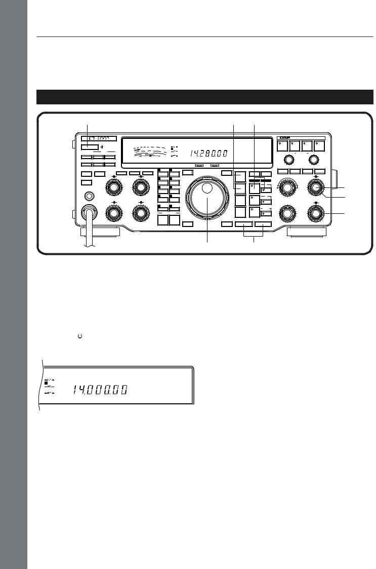
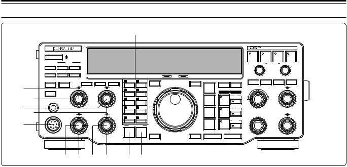
FRONT PANEL
qw
|
e |
|
ATT |
|
|
|
|
|
|
|
|
|
ANT |
DOWN |
UP |
|
|
|
|
|
|
|
|
t |
r |
VOX |
FULL/SEMI |
AIP |
|
|
|
|
|
|
|
|
|
|
|
|
HF TRANSCEIVER |
|
TS-870 |
|
ON AIR |
||
|
y u |
AT TUNE |
THRU/AUTO |
|
METER |
PROC |
MONI |
1 |
CH 1 |
6 |
M.IN |
|
SEND |
|
AGC |
KEY SPEED |
PROC |
MONI |
|
|
|
ENTER |
|
|
i |
|
|
|
4 |
6 |
2 |
CH 2 |
7 |
M>VFO |
|
|
|
|
|
|
|
8 |
3 |
CH 3 |
8 |
SCAN |
|
|
|
|
|
|
|
2 |
|||||
|
|
PHONES |
|
|
|
|
|
|
|
|
|
|
o |
|
SLOW |
|
FAST |
|
|
|
|
|
|
|
|
|
OFF |
|
0 |
1 0 |
4 |
CH 4 |
9 |
CLR |
|
|
|
MIC |
|
CAR |
DELAY |
MIC |
PWR |
|
|
|
|
|
|
|
|
4 |
6 |
4 |
6 |
5 |
REC |
0 |
F.LOCK |
|
|
|
|
|
|
|
|
||||
|
|
|
2 |
|
8 |
2 |
8 |
|
QUICK MEMO |
||
|
|
|
|
|
|
|
|
|
|
|
FINE |
|
|
|
|
0 |
1 0 |
0 |
1 0 |
|
|
|
|
|
|
|
|
|
|
|
|
|
M.IN |
|
MR |
!0 !1!2 !3
q  (POWER) switch
Press and hold down briefly to switch the transceiver power ON. Press again to switch OFF the power {page 19}.
w ATT DOWN/UP buttons
Press either button to step up or down through the available receive signal attenuator selections. The attenuator is OFF when all three selections of 6, 12, and 18 dB are not lit {page 53}.
e ANT button
Press to select Antenna 1 or Antenna 2 that are connected to their respective antenna connectors on the Rear Panel {pages 2, 63}.
r VOX button
In the voice modes, press to switch the Voice-Operated Transmit function ON or OFF {page 45}. In CW mode, switches the Break-in function ON or OFF {page 31}.
t FULL/SEMI button
In CW mode, press to select Full or Semi Break-in operation which affects the transmit/receive recovery time after sending stops {page 31}.
y AIP button
Press to switch the Advanced Intercept Point function ON or OFF. When activated, the AIP function reduces interference caused by the presence of very strong signals. The function lowers the receive sensitivity by about 10 dB, and the default is ON when frequencies below 7490 kHz are selected {page 53}.
DIGITAL SIGNAL PROCESSOR
|
|
|
AUTO |
BEAT |
|
|
|
|
|
|
NOTCH |
CANCEL |
N.R. |
|
TX EQ. |
|
|
|
LO/WIDTH FILTER |
HI/SHIFT |
|||
AT TUNE |
|
|
RIT |
XIT |
CLEAR |
NB |
|
|
|
|
|||||
|
MODE |
A=B |
MENU |
|
|
|
|
TF-SET |
LSB |
|
RIT/XIT |
|
AF |
RF |
|
|
|
|
|
|
4 |
6 |
|
|
/USB |
RX |
TX |
|
|
|
|
|
|
|
A |
|
|
|
|
|
|
|
|
|
2 |
|
8 |
|
CW/ó R |
|
|
|
|
|
|
|
|
|
B |
|
|
0 |
1 0 |
|
FSK |
|
M.CH/VFO.CH |
|
NB |
SQL |
|
|
/ó R |
|
|
||||
|
|
|
|
|
4 |
6 |
|
|
|
|
|
|
|
||
|
|
|
M.CH |
|
|
|
|
|
FM/AM |
|
|
|
2 |
|
8 |
|
|
|
|
|
|
|
|
1MHz |
DOWN |
|
UP |
|
|
|
|
|
|
|
|
|
|
0 |
1 0 |
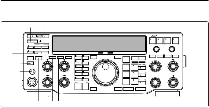
u AT TUNE button
After enabling the internal antenna tuner via the THRU/AUTO button, press to activate the tuner. The tuner will attempt to match the transceiver with the antenna system {page 49}.
i SEND button
Press to switch the transceiver between receive and transmit {page 23}.
o PHONES jack
Connect headphones to this jack. Inserting a plug into this jack automatically mutes the audio from the speaker {page 4}.
!0THRU/AUTO button
Press to enable the internal antenna tuner. This button does not start the tuning action (see u). The tuner can be configured so that it is only in-line while transmitting, or it can be in-line while both transmitting and receiving {page 49}.
!1METER button
Press to switch between the available functions on the Front Panel meter {page 22}.
!2PROC button
In SSB or AM mode, press to switch the Speech Processor ON or OFF {pages 23, 46}.
!3MONI button
Press to switch the Transmit Monitor function ON or OFF so you can monitor your transmitted signal {page 46}.
10
3 GETTING ACQUAINTED
!5
!6 !7!8
!9
!4
DIGITAL SIGNAL PROCESSOR
|
|
|
|
|
|
|
|
|
|
|
|
|
AUTO |
BEAT |
|
|
|
|
|
|
|
|
|
|
|
|
|
|
|
|
NOTCH |
CANCEL |
N.R. |
|
TX EQ. |
|
ATT |
|
|
|
|
|
|
|
|
|
|
LO/WIDTH FILTER |
HI/SHIFT |
||||
ANT |
DOWN |
UP |
|
|
|
|
|
|
|
|
|
|
|||||
VOX |
FULL/SEMI |
AIP |
|
|
|
|
|
|
|
|
|
|
|
|
|
|
|
|
|
|
|
HF TRANSCEIVER |
|
TS-870 |
|
ON AIR |
AT TUNE |
|
|
RIT |
XIT |
CLEAR |
NB |
||
|
|
|
|
|
|
|
|
|
|
|
|
|
|||||
AT TUNE |
THRU/AUTO |
|
METER |
PROC |
MONI |
1 |
CH 1 |
6 |
M.IN |
|
MODE |
A=B |
MENU |
|
|
|
|
SEND |
|
AGC |
KEY SPEED |
PROC |
MONI |
|
|
|
ENTER |
TF-SET |
LSB |
|
RIT/XIT |
|
AF |
RF |
|
|
|
|
4 |
6 |
2 |
CH 2 |
7 |
|
|
|
|
4 |
6 |
||||
|
|
|
M>VFO |
|
/USB |
RX |
TX |
|
|
||||||||
|
|
|
|
|
|
|
|
|
|
|
|
|
|
|
|
||
|
|
|
|
|
|
|
|
|
|
|
|
|
A |
|
|
|
|
|
|
|
|
2 |
8 |
3 |
CH 3 |
8 |
SCAN |
|
|
|
|
|
2 |
|
8 |
PHONES |
|
|
|
|
|
|
|
|
|
|
CW/ó R |
|
|
|
|
|
|
|
SLOW |
|
FAST |
|
|
|
|
|
|
|
|
|
|
|
|
|
|
|
|
OFF |
|
0 |
1 0 |
4 |
CH 4 |
9 |
CLR |
|
|
|
B |
|
|
0 |
1 0 |
MIC |
|
CAR |
DELAY |
MIC |
PWR |
|
|
|
|
|
FSK |
|
M.CH/VFO.CH |
|
NB |
SQL |
|
|
|
|
|
|
|
/ó R |
|
|
|||||||||
|
|
4 |
6 |
4 |
6 |
|
|
|
|
|
|
|
|
|
4 |
6 |
|
|
|
5 |
REC |
0 |
F.LOCK |
|
|
|
|
|
|
||||||
|
|
|
|
|
|
|
|
|
|
|
|
|
|
||||
|
|
|
|
|
|
|
|
|
|
|
|
|
M.CH |
|
|
|
|
|
2 |
|
8 |
2 |
8 |
|
QUICK MEMO |
|
FM/AM |
|
|
|
2 |
|
8 |
||
|
|
|
|
|
|
|
|
|
|
|
|
|
|
|
|
|
|
|
|
|
|
|
|
|
|
|
FINE |
1MHz |
DOWN |
|
UP |
|
|
|
|
|
|
0 |
1 0 |
0 |
1 0 |
|
|
|
|
|
|
|
|
|
|
0 |
1 0 |
|
|
|
|
|
|
|
M.IN |
|
MR |
|
|
|
|
|
|
|
|
@0 @1 @2 @3 |
@4@5 |
!4Multi-purpose keypad
Consists of 10 buttons that are used for inputting numeric data. Also used for other functions:
•[M.IN]: Writes data into memory channels
{page 54}, selects Memory Scroll mode {page 56}, and adds items to the Quick Menu {page 24}.
•[M>VFO]: Transfers data from a memory channel to a VFO {page 56}.
•[SCAN]: Starts and stops Scan functions {page 60}.
•[CH 1], [CH 2], [CH 3], [CH 4]: Selects functions associated with the internal electronic keyer {page 32} and the DRU-3 Digital Recording Unit {page 67}.
•[REC]: Selects the record mode for the DRU-3 Digital Recording Unit {page 67}.
•[F.LOCK]: Controls the Frequency Lock function {page 64}.
•[CLR]: Used to exit from, abort, or reset various functions. Also used for erasing memory channels {page 57} or locking out {page 62} memory channels from the scan list.
!5AGC control
Turn to adjust the AGC time constant after selecting the manual AGC mode {page 44}.
!6KEY SPEED control
In CW mode, turn clockwise to increase the internal electronic keyer speed and counterclockwise to decrease the speed {page 32}.
!7PROC control
When using the Speech Processor in SSB or AM mode, adjusts the compression level. Turning the control clockwise increases compression {pages 23, 46}.
!8MONI control
When using the Transmit Monitor function, adjusts the volume level of the monitored transmit audio. Also adjusts the volume of the CW sidetone. Turning the control clockwise increases the volume {pages 30, 46}.
!9MIC connector
Connect a compatible microphone, then snugly screw down the connector locking ring {page 4}.
@0CAR control
In CW, FSK, or AM mode, adjusts the carrier level {pages 23, 30, 40, 41}. When using the Speech Processor in SSB mode, adjusts the processor output {page 46}. Turning the control clockwise increases the carrier level or the processor output.
@1DELAY control
When using the VOX function or the CW Break-in function, adjusts the time period that the transceiver waits before changing from the transmit mode back to the receive mode. Turning the control clockwise increases the delay {pages 31, 45}.
@2MIC gain control
In SSB or AM mode, adjusts the level of microphone gain. Turning the control clockwise increases the gain {pages 23, 29, 40}.
@3PWR control
Adjusts the transmit output power in all modes. Turning the control clockwise increases the output power {page 23}.
@4QUICK MEMO M.IN button
Press to write data into Quick memory {page 59}.
@5QUICK MEMO MR button
Press to recall data from Quick memory {page 59}.
11
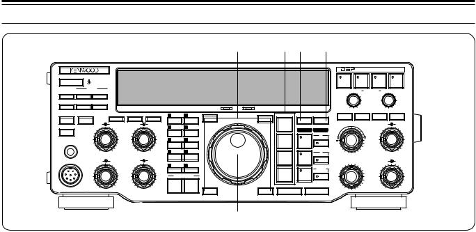
3 GETTING ACQUAINTED
|
|
|
|
|
|
|
|
|
@6 |
|
@8@9 |
#0 |
|
|
|
|
|
|
|
|
|
|
|
|
|
|
|
|
|
|
|
|
|
DIGITAL SIGNAL PROCESSOR |
|||
|
|
|
|
|
|
|
|
|
|
|
|
|
AUTO |
BEAT |
|
|
|
|
|
|
|
|
|
|
|
|
|
|
|
|
|
NOTCH |
CANCEL |
N.R. |
|
TX EQ. |
|
|
ATT |
|
|
|
|
|
|
|
|
|
|
LO/WIDTH |
FILTER |
HI/SHIFT |
||||
ANT |
DOWN |
UP |
|
|
|
|
|
|
|
|
|
|
||||||
VOX |
FULL/SEMI |
AIP |
|
|
|
|
|
|
|
|
|
|
|
|
|
|
|
|
|
|
|
|
HF TRANSCEIVER |
|
TS-870 |
|
ON AIR |
AT TUNE |
|
|
RIT |
XIT |
|
CLEAR |
NB |
||
|
|
|
|
|
|
|
|
|
|
|
|
|
|
|||||
AT TUNE |
THRU/AUTO |
|
METER |
PROC |
MONI |
1 |
CH 1 |
6 |
M.IN |
|
MODE |
A=B |
MENU |
|
|
|
|
|
SEND |
|
AGC |
KEY SPEED |
PROC |
MONI |
|
|
|
ENTER |
TF-SET |
LSB |
|
RIT/XIT |
|
|
AF |
RF |
|
|
|
|
4 |
6 |
2 |
CH 2 |
7 |
|
|
|
|
|
4 |
6 |
||||
|
|
|
M>VFO |
|
/USB |
RX |
TX |
|
|
|
||||||||
|
|
|
|
|
|
|
|
|
|
|
|
|
A |
|
|
|
|
|
|
|
|
|
2 |
8 |
3 |
CH 3 |
8 |
SCAN |
|
|
|
|
|
|
2 |
|
8 |
PHONES |
|
|
|
|
|
|
|
|
|
|
CW/ó R |
|
|
|
|
|
|
|
|
SLOW |
|
FAST |
|
|
|
|
|
|
|
|
|
|
|
|
|
|
|
|
|
OFF |
|
0 |
1 0 |
4 |
CH 4 |
9 |
CLR |
|
|
|
B |
|
|
|
0 |
1 0 |
MIC |
|
CAR |
DELAY |
MIC |
PWR |
|
|
|
|
|
FSK |
|
M.CH/VFO.CH |
|
|
NB |
SQL |
|
|
|
|
|
|
|
/ó R |
|
|
|
|||||||||
|
|
4 |
6 |
4 |
6 |
|
|
|
|
|
|
|
|
|
|
4 |
6 |
|
|
|
5 |
REC |
0 |
F.LOCK |
|
|
|
|
|
|
|
||||||
|
|
|
|
|
|
|
|
|
|
|
|
|
|
|
||||
|
|
|
|
|
|
|
|
|
|
|
|
|
M.CH |
|
|
|
|
|
|
2 |
|
8 |
2 |
8 |
|
QUICK MEMO |
|
FM/AM |
|
|
|
|
2 |
|
8 |
||
|
|
|
|
|
|
|
|
|
|
|
|
|
|
|
|
|
|
|
|
|
|
|
|
|
|
|
|
FINE |
1MHz |
DOWN |
|
UP |
|
|
|
|
|
|
|
0 |
1 0 |
0 |
1 0 |
|
|
|
|
|
|
|
|
|
|
|
0 |
1 0 |
|
|
|
|
|
|
|
M.IN |
|
MR |
|
|
|
|
|
|
|
|
|
@7
@6Programmable Function buttons
The functions of these four buttons are selected and assigned by you so you can customize the transceiver as you like {page 63}. The factory default assignments are as follows:
ENTER button
Used when entering frequencies via the keypad {page 22}.
TF-SET (Transmit Frequency Set) button
While operating split frequency, press to monitor the transmit frequency. Also, while holding this button down in split-frequency mode, the transmit frequency can be changed without altering the receive frequency {page 43}.
FINE button
Press to reduce the Tuning control step size by one-tenth to allow more precise tuning {page 21}.
1MHz button
Press to switch between the 1MHz mode and the Amateur band mode {page 20}. This button also activates the Programmed channel and Vacant channel search modes {page 55}.
@7Tuning control
Turn to select the desired frequency. Use the convenient finger-tip cavity for continuous tuning {page 21}.
@8Mode buttons
Press these buttons to select your operating mode {page 20}.
LSB/USB button
Selects Lower Sideband or Upper Sideband mode for voice {page 29} or digital operation {page 41}.
CW/–R button
Selects CW {page 30} or CW Reverse mode {page 31}.
FSK/–R button
Selects Frequency Shift Keying {page 40} or Frequency Shift Keying Reverse mode for RTTY operation {page 41}.
FM/AM button
Selects FM {page 38} or AM mode {page 40}.
@9A=B button
Press to equalize the data in both VFOs. The data in the currently selected VFO is copied to the other VFO; the current VFO’s data is unaffected {page 20}. This button is also used for the Full Reset function
{pages 57, 63}.
#0MENU button
Press to select or cancel the Menu mode that is used for activating and configuring functions {page 24}. This button is also used for changing the Automatic mode boundaries {page 48}.
12
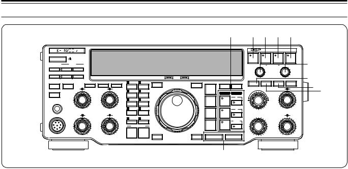
|
|
|
|
|
|
|
|
|
|
|
|
|
|
|
3 GETTING ACQUAINTED |
|||||
|
|
|
|
|
|
|
|
|
|
|
|
#1 |
#2 #3#4 #5 |
|
||||||
|
|
|
|
|
|
|
|
|
|
|
|
|
|
|
|
DIGITAL SIGNAL PROCESSOR |
|
|
||
|
|
|
|
|
|
|
|
|
|
|
|
|
|
AUTO |
BEAT |
|
|
|
|
#6 |
|
|
|
|
|
|
|
|
|
|
|
|
|
|
NOTCH |
CANCEL |
N.R. |
TX EQ. |
|||
|
ATT |
|
|
|
|
|
|
|
|
|
|
|
LO/WIDTH |
FILTER |
HI/SHIFT |
|
||||
ANT |
DOWN |
UP |
|
|
|
|
|
|
|
|
|
|
|
|
||||||
VOX |
FULL/SEMI |
AIP |
|
|
|
|
|
|
|
|
|
|
|
|
|
|
|
|
|
#7 |
|
|
|
|
HF TRANSCEIVER |
|
TS-870 |
|
ON AIR |
AT TUNE |
|
|
|
RIT |
XIT |
|
CLEAR |
NB |
|||
|
|
|
METER |
PROC |
MONI |
|
|
|
|
|
|
|
|
|
||||||
AT TUNE |
THRU/AUTO |
|
1 |
CH 1 |
6 |
M.IN |
|
MODE |
A=B |
MENU |
|
|
|
|
|
|
#9 |
|||
|
|
AGC |
KEY SPEED |
PROC |
MONI |
|
|
|
|
|
|
RX |
TX |
RIT/XIT |
|
|
AF |
RF |
||
SEND |
|
|
|
|
ENTER |
TF-SET |
LSB |
|
|
|
|
#8 |
||||||||
|
|
|
4 |
6 |
2 |
CH 2 |
7 |
|
|
|
|
|
|
4 |
6 |
|
||||
|
|
|
M>VFO |
|
/USB |
|
|
|
|
|
|
|
||||||||
|
|
|
|
|
|
|
|
|
|
|
|
|
A |
|
|
|
|
|
|
|
|
|
|
|
2 |
8 |
3 |
CH 3 |
8 |
SCAN |
|
|
|
|
|
|
|
2 |
|
8 |
|
PHONES |
|
|
|
|
|
|
|
|
|
|
CW/ó R |
|
|
|
|
|
|
|
|
|
|
SLOW |
|
FAST |
|
|
|
|
|
|
|
|
|
|
|
|
|
|
|
|
|
|
|
|
|
|
|
|
|
|
|
|
|
|
|
|
|
|
|
|
||
|
|
OFF |
|
0 |
1 0 |
4 |
CH 4 |
9 |
CLR |
|
|
|
B |
|
|
|
|
0 |
1 0 |
|
MIC |
|
CAR |
DELAY |
MIC |
PWR |
|
|
|
|
|
FSK |
|
|
M.CH/VFO.CH |
|
|
NB |
SQL |
|
|
|
|
|
|
|
|
/ó R |
|
|
|
|
|
|||||||||
|
|
4 |
6 |
4 |
6 |
5 |
REC |
0 |
F.LOCK |
|
|
|
|
|
|
|
|
4 |
6 |
|
|
|
|
|
|
|
|
|
|
|
|
|
|
|
|
|
|
||||
|
|
|
|
|
|
|
|
|
|
|
|
|
M.CH |
|
|
|
|
|
|
|
|
2 |
|
8 |
2 |
8 |
|
QUICK MEMO |
|
FM/AM |
|
|
|
|
|
2 |
|
8 |
|
||
|
|
|
|
|
|
|
|
|
|
|
|
|
|
|
|
|
|
|
|
|
|
|
|
|
|
|
|
|
|
FINE |
1MHz |
DOWN |
|
UP |
|
|
|
|
|
|
|
|
|
0 |
1 0 |
0 |
1 0 |
|
|
|
|
|
|
|
|
|
|
|
|
0 |
1 0 |
|
|
|
|
|
|
|
|
M.IN |
|
MR |
|
|
|
|
|
|
|
|
|
|
|
$0
Note: Only Auto Notch #2, or Beat Cancel #3, or Noise Reduction #4can be used at one time. They cannot be activated at the same time.
#1VFO/ Memory channel buttons
Press to select VFO A, VFO B, or a memory channel for receive or transmit. If a receive button is pressed, the same VFO or memory channel is selected for transmit and receive. However, pressing a transmit button selects only that VFO or memory channel for transmit {page 42}.
RX A button
Selects VFO A for receive and transmit {page 19}.
TX A button
Selects VFO A for transmit {page 42}.
RX B button
Selects VFO B for receive and transmit {page 19}.
TX B button
Selects VFO B for transmit {page 42}.
RX M.CH button
Selects memory channel mode for receive and transmit {page 55}.
#4N.R. button
In SSB, CW, FSK, or AM mode, press to switch the Noise Reduction function ON or OFF. This function offers a choice of digital filtering methods for reception {page 53}.
#5TX EQ. button
In SSB or AM mode, press to switch the Transmit Equalizer function ON or OFF. This equalizer function includes high boost, low boost, and comb filter functions {page 47}.
#6FILTER LO/WIDTH and HI/SHIFT controls
These controls allow total flexibility in all modes for digitally changing the receive pass band characteristics for optimum reception {pages 51, 52}.
#7RIT button
Press to switch the Receive Incremental Tuning function ON or OFF. The RIT function allows you to change your receive frequency without affecting your transmit frequency {page 44}.
#8CLEAR button
TX M.CH button
Selects memory channel mode for transmit {page 42}.
#2AUTO NOTCH button
Press to reset the RIT/XIT frequency offset to zero {pages 44, 45}. Also erases entered digits at any time the keypad is being used to enter data {page 22, 48}.
#9XIT button
In SSB mode, press to switch the Auto Notch function ON or OFF. Auto Notch can automatically locate and remove interfering signals from the receive IF pass band {page 52}.
#3BEAT CANCEL button
In SSB or AM mode, press to switch the Beat Cancel function ON or OFF. Beat Cancel works at AF to remove interfering signals {page 52}.
Press to switch the Transmit Incremental Tuning function ON or OFF. The XIT function allows you to change your transmit frequency without affecting your receive frequency {page 45}.
$0UP/DOWN buttons
Press to step through all Amateur bands consecutively {page 20}. If the 1MHz Step function is ON, then pressing these buttons steps the transceiver in 1 MHz increments {page 20}. These buttons are also used to make selections from the Menu {page 24}, and to check Start and End frequencies for the Scan function
{page 60}.
13
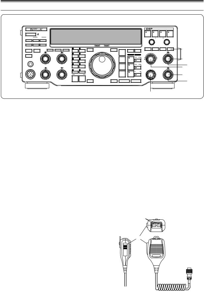
3 GETTING ACQUAINTED
|
ATT |
|
|
|
|
|
|
|
|
ANT |
DOWN |
UP |
|
|
|
|
|
|
|
VOX |
FULL/SEMI |
AIP |
|
|
|
|
|
|
|
|
|
|
|
HF TRANSCEIVER |
|
TS-870 |
|
ON AIR |
|
AT TUNE |
THRU/AUTO |
|
METER |
PROC |
MONI |
1 |
CH 1 |
6 |
M.IN |
SEND |
|
AGC |
KEY SPEED |
PROC |
MONI |
|
|
|
ENTER |
|
|
|
4 |
6 |
2 |
CH 2 |
7 |
M>VFO |
|
|
|
|
|
2 |
8 |
3 |
CH 3 |
8 |
SCAN |
PHONES |
|
|
|
|
|
|
|
|
|
|
SLOW |
|
FAST |
|
|
|
|
|
|
|
|
OFF |
|
0 |
1 0 |
4 |
CH 4 |
9 |
CLR |
MIC |
|
CAR |
DELAY |
MIC |
PWR |
|
|
|
|
|
|
4 |
6 |
4 |
6 |
5 |
REC |
0 |
F.LOCK |
|
|
|
|
|
|
||||
|
2 |
|
8 |
2 |
8 |
|
QUICK MEMO |
||
|
|
|
|
|
|
|
|
|
FINE |
|
|
0 |
1 0 |
0 |
1 0 |
|
|
|
|
|
|
|
|
|
|
|
M.IN |
|
MR |
$1NB button
Press to switch the analog Noise Blanker function ON or OFF. This function works best against short duration pulse noise {page 53}.
$2AF gain control
Adjusts the audio frequency gain. Turn the control clockwise to increase the gain; counterclockwise to decrease the gain {page 19}.
$3RF gain control
Adjusts the radio frequency gain. Turn the control clockwise to increase the gain; counterclockwise to decrease the gain {page 19}.
$4RIT/XIT control
After switching ON the RIT or XIT function, turn to select the desired frequency offset with respect to the current frequency {pages 44, 45}.
$5NB control
When using the Noise Blanker function, turn to adjust the noise blanking level {page 53}. To prevent distorting your receive signal, use the minimum blanking level necessary.
$6SQL control
The Squelch control can be used for muting the receiver during no signal periods. The more clockwise that the control is turned, the higher the noise threshold level. Therefore, the stronger the received signal must be to open the squelch. Leave fully counterclockwise for weak signal reception {page 19}.
DIGITAL SIGNAL PROCESSOR
|
|
|
AUTO |
BEAT |
|
|
|
|
|
|
|
|
NOTCH |
CANCEL |
N.R. |
|
TX EQ. |
|
|
|
|
|
LO/WIDTH FILTER |
HI/SHIFT |
|
|
|||
AT TUNE |
|
|
RIT |
XIT |
CLEAR |
NB |
|
|
|
|
|
|
|
$1 |
|||||
|
MODE |
A=B |
MENU |
|
|
|
|
|
|
TF-SET |
LSB |
|
RIT/XIT |
|
AF |
RF |
|
|
|
|
|
|
|
|
4 |
6 |
|
|
|
|
/USB |
RX |
TX |
|
|
|
|
|
|
|
|
|
A |
|
|
|
|
|
$2 |
|
|
|
|
|
2 |
|
|
8 |
|
|
CW/ó R |
|
|
|
|
|
|
|
$3 |
|
|
|
B |
|
|
0 |
1 0 |
|
|
|
FSK |
|
M.CH/VFO.CH |
|
NB |
SQL |
|
$4 |
|
|
/ó R |
|
|
|
|||||
|
|
|
|
|
4 |
6 |
|
||
|
|
|
M.CH |
|
|
|
|
|
$5 |
|
FM/AM |
|
|
|
2 |
|
|
8 |
|
|
|
|
|
|
|
|
|
||
1MHz |
DOWN |
|
UP |
|
|
|
|
|
$6 |
|
|
|
|
|
|
0 |
1 0 |
|
|
$7
$7M.CH/VFO.CH control
In VFO mode, turn to step the frequency up or down {page 21}. In memory channel mode, turn to select the desired memory channel {page 55}. The control is also used for selecting boundaries for the Automatic Mode function {page 48} and for selecting Menu numbers when accessing the Menu {page 24}.
MICROPHONE
q UP/DWN buttons
Use these buttons to step the VFO frequency or memory channels up or down. The selected frequency or channel will change continuously in the direction of the button label if a button is pressed and held down.
w PTT (Push-to-Talk) switch
The transceiver is placed in transmit mode when this non-locking switch is held down. Releasing the switch returns the transceiver to receive mode.
q
DWN UP
w
PTT
14
3 GETTING ACQUAINTED
REAR PANEL
q |
w |
e |
r |
ANT 2 |
ANT 1 |
DC 13.8V |
AT |
|
|
20.5A |
|
GND |
|
|
|
EXT |
|
|
EXT SP |
|
|
|
COM |
|
RX ANT |
IF OUT 1 |
REMOTE |
8 Ω |
ACC 2 |
KEY |
PADDLE |
||
RT TY |
t y u |
i o !0 |
!1 !2 |
q GND post with wing nut
Connect a heavy gauge wire or copper strap between the ground post and the nearest earth ground {page 3}. Do not connect the ground wire to either your house electrical wiring, or gas or water pipes. A well-grounded transceiver will reduce the risk of interference to television, broadcast radio receivers, and other electronic devices. A good ground can also reduce receiver noise caused by static discharges.
w ANT 1 and ANT 2 connectors
Connect the feed lines from your antennas to these connectors. Refer to pages 2 and 63 for details.
e Power Input DC 13.8 V connector
Connect a 13.8 V DC power source {page 3}. Use the supplied cable with a regulated DC power supply. The TS-870S draws less than 20.5 A at maximum transmit output.
r AT connector
Mates with the connector on the cable supplied with the AT-300 antenna tuner. Refer to the instruction manual supplied with this tuner for more information.
t EXT RX ANT jack
Mates with an RCA pin plug for connecting a separate receiver. Menu No. 53 enables this jack. Never transmit into this jack. Signals received by the TS-870S are distributed via a power divider to the TS-870S receive stage and the external receiver. Therefore, connecting an external receiver reduces the signal level.
y IF OUT 1 jack
Mates with an RCA pin plug for connecting the 8.83 MHz IF for pan display of an SM-230 Station Monitor {page 6}.
u REMOTE connector
i EXT SP jack
Mates with a 3.5 mm (1/8") diameter, 2-conductor (mono) plug for connecting an external speaker {page 4}. Connecting an external speaker cuts off the audio automatically to the internal speaker.
o ACC 2 connector
Mates with a 13-pin male DIN connector for connecting various accessory equipment {page 6}.
!0PADDLE and KEY jacks
Mates with a 6.0 mm (1/4") 3-conductor plug and a 3.5 mm (1/8") 2-conductor plug for connecting a key paddle for the internal electronic keyer and another key for CW operation respectively. Read “Keys and Keyboards for CW Operation” {page 4} before connecting to these jacks.
!1RTTY jack
Mates with an RCA pin plug for connecting the RTTY key output from RTTY equipment to operate true frequency shift keying (direct keying) {page 5}.
!2COM connector
Mates with a 9-pin female RS-232C connector for connecting a computer via one of its serial communication ports {page 83}. Functions on the transceiver can be controlled remotely by using a communications program on the computer {pages 5, 83}. Also used with the Quick Data Transfer function {page 65}.
Note: Before using the REMOTE, ACC 2, and COM connectors, remove the protective covers.
Mates with a 7-pin male DIN connector for connecting a linear amplifier {page 5}.
15
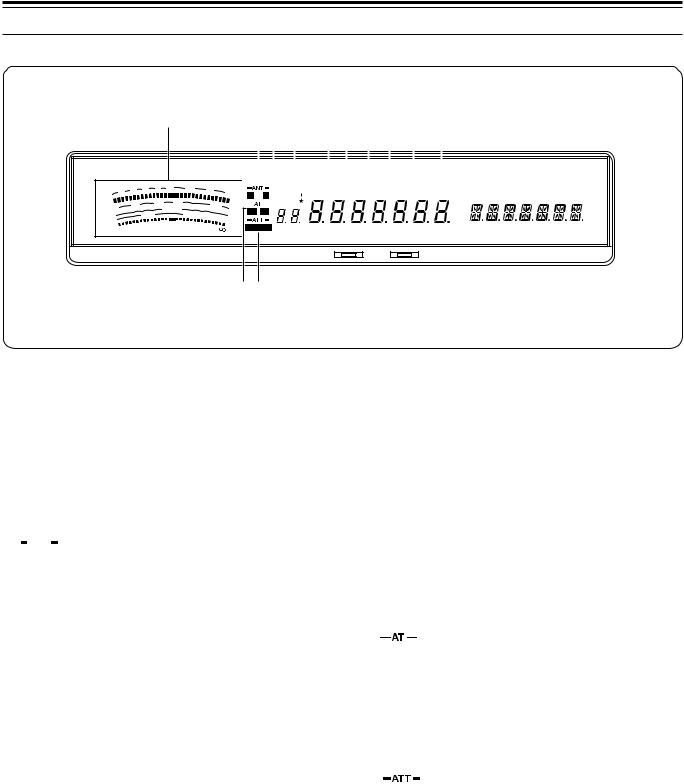
3 GETTING ACQUAINTED
DISPLAY
q
S |
|
1 |
3 |
5 |
7 |
9 |
20 |
|
|
|
|
|
|
||
|
|
|
|
25 |
|
|
|
|
|
|
10 |
|
50 |
|
|
|
|
|
|
|
|
||
PWR |
0 |
|
|
|
FILTER |
|
|
|
|
|
|
|
|||
|
|
|
|
ALC |
|
|
|
SWR |
|
1 |
1.5 |
|
10 2 |
3 |
20 |
COMP |
|
|
|
|
|
||
HF TRANSCEIVER
|
|
|
|
we t |
u i o !0 !1 !2 |
|
|
|
|
|||||||||||||||||||||
|
|
|
|
|
|
|
|
r |
y |
|
|
|
|
|
|
|
|
|
|
|
|
|
|
|
|
|
||||
|
|
|
|
|
|
|
|
|
|
|
|
|
|
|
|
|
|
|
|
|
|
|
|
|
|
|
|
|
|
|
|
|
|
|
|
|
|
|
|
|
|
|
|
|
|
|
|
|
|
|
|
|
|
|
|
|
|
|
|
||
40 |
60 |
|
|
|
|
|
|
VOX |
FULL |
SEMI AIP AGC |
AUTO |
PROC |
MONI |
MENU |
SPLIT |
TONE |
NB |
CTRL |
||||||||||||
|
dB |
|
|
|
|
|
|
|
|
|
|
|
|
|
|
|
|
|
|
|
|
|
A B |
RIT |
XIT |
WIDTH SHIFT |
||||
100 |
W |
|
|
|
|
|
M.CH |
|
|
|
|
|
|
|
|
|
|
|
|
|
|
|
|
|
|
|||||
|
|
|
|
|
|
|
|
|
|
|
|
|
|
|
|
|
|
|
|
|
|
|
|
|
|
|
|
|||
|
|
|
|
|
|
|
|
|
|
|
|
|
|
|
|
|
|
|
|
|
|
|
|
|
|
|
|
|
||
|
d |
|
|
|
|
|
|
|
|
AUTO |
|
LSB USB CW |
R |
FSK FM |
AM |
M. SCR |
PRG SCAN F. LOCK |
FINE MHz |
||||||||||||
|
|
|
|
|
|
|
|
|
|
|||||||||||||||||||||
TS-870 |
B |
|
|
|
|
|
|
|
|
|||||||||||||||||||||
|
|
|
|
|
|
|
|
|
|
|
|
ON AIR |
|
|
|
|
AT TUNE |
|
|
|
|
|
|
|
||||||
|
|
|
|
|
|
|
|
|
|
|
|
|
|
|
|
|
|
|
|
|
|
|
||||||||
!3!4
q METER
While receiving, serves as an S-meter to measure and display the received signal strength. Also while receiving, a 30-segment display represents the width and relative shift of the currently selected receive pass band. While transmitting, serves as a calibrated power meter plus an ALC meter, an SWR meter, or a Speech Processor compression meter. A Peak Hold function can be activated that holds each reading for about 2.5 seconds {page 22}.
w 


Either z or x lights while Antenna 1 or Antenna 2 is selected respectively. Only one antenna can be selected at a time {pages 2, 63}.
e M.CH
Lights while the memory channel mode is selected. Also lights while using the Memory Scroll function {page 56}.
r VOX
Lights while the Voice-Operated Transmit function {page 45} is ON. For CW operation, lights while the Break-in function {page 31} is ON.
t 
Lights when a Menu item is added to the Quick Menu {page 24}.
y FULL
Lights while CW Full Break-in is selected {page 31}.
u SEMI
Lights while CW Semi Break-in is selected {page 31}.
i AIP
o AGC
Lights while the Automatic Gain Control function is ON {page 44}.
!0AUTO
Lights while Automatic is selected for the Automatic Gain Control function {page 44}.
!1PROC
Lights while the Speech Processor is ON {pages 23, 46}.
!2MONI
Lights while the Transmit Monitor function is ON {page 46}.
!3

 lights while the internal antenna tuner is configured for use while transmitting only.
 light while the tuner is configured for use while transmitting and receiving. If neither are lit, the antenna tuner is switched OFF {page 49}. If using Full Break-in CW, the internal tuner can be either bypassed completely or can be in-line for both transmitting and receiving.
!4

n, ⁄2, or ⁄8lights while the attenuator is switched ON. The numbers indicate the amount in dB of receive attenuation that is selected. If no numbers are lit, the attenuator is switched OFF {page 53}.
Lights while the Advanced Intercept Point function is ON {page 53}.
16
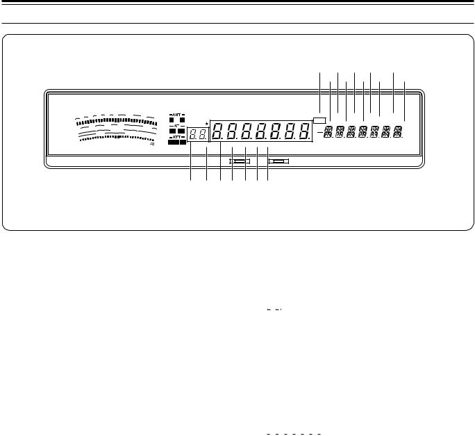
3 GETTING ACQUAINTED
|
|
1 |
3 |
5 |
7 |
9 |
20 |
40 |
60 |
|
S |
|
|
|
|
|
|
|
dB |
||
|
|
|
|
|
|
|
|
|||
|
|
|
|
25 |
|
|
|
|
||
|
|
|
10 |
|
50 |
|
100 |
|
|
|
PWR |
0 |
|
|
|
FILTER |
|
W |
|||
|
|
|
|
|
|
|||||
|
|
|
|
ALC |
|
|
|
|
|
|
SWR |
|
1 |
1.5 |
|
10 2 |
3 |
20 |
|
dB |
|
COMP |
|
|
|
|
|
|
||||
HF TRANSCEIVER |
TS-870 |
!5 !7 !9@1 @3 !6!8 @0@2 @4
VOX FULL SEMI AIP AGC AUTO PROC MONI MENU SPLIT TONE NB |
CTRL |
A B  RIT
RIT  XIT
XIT WIDTH SHIFT
M.CH
AUTO |
LSB USB CW R FSK FM AM M. SCR PRG SCAN F. LOCK FINE MHz |
ON AIR |
AT TUNE |
@5@6@7@8@9#0#1
!5MENU
Lights while Menu mode is being accessed. Flashes when the Menu has been temporarily reset {page 24}.
!6A/B
“A” lights while Menu A is being accessed. “B” lights while Menu B is being accessed {page 24}.
!7SPLIT
Lights while a different transmit and receive frequency are selected for split frequency {page 42}.
!8RIT
Lights while the Receive Incremental Tuning function is ON {page 44}.
!9TONE
In FM mode, lights while the subaudible Tone function is ON while operating split frequency {page 39}.
@0XIT
Lights while the Transmit Incremental Tuning function is ON {page 45}.
@1NB
Lights while the Noise Blanker is ON {page 53}.
@2WIDTH
In all modes except SSB and AM, lights after the LO/WIDTH control is adjusted. Indicates that the number reported below it on the Display is the receive bandwidth {page 52}.
@3CTRL
Lights while data is being exchanged between a computer and the transceiver during computer control {page 50} or between two transceivers during Quick Data Transfer {page 65}.
@4SHIFT
In CW, lights after the HI/SHIFT control is adjusted. Indicates that the number reported below it on the Display is the shift of the receive pass band {page 51}.
@5 

Shows the selected memory channel {page 55}, Menu No.{page 24}, and Automatic Mode boundary numbers {page 48}. The dot lights while a memory channel is locked out. This indicates that the channel will be skipped during Memory Scan {page 62}.
@6AUTO
Lights while Automatic Mode is ON {page 48}. Automatic Mode automatically controls the operating mode according to instructions that you provide.
@7


Shows the operating frequency to a resolution of 10 Hz {page 20}. Also shows the Menu selections while in Menu mode {page 24}.
@8LSB
Lights while in the Lower Sideband operating mode {page 20}.
@9USB
Lights while in the Upper Sideband operating mode {page 20}.
#0CW
Lights while in the CW operating mode {page 20}.
#1 R
Lights while the Reverse function is used with FSK or CW. The Reverse function reverses the mark and space frequency relationship for FSK {page 20}, and uses the opposite sideband for CW {page 20}.
17
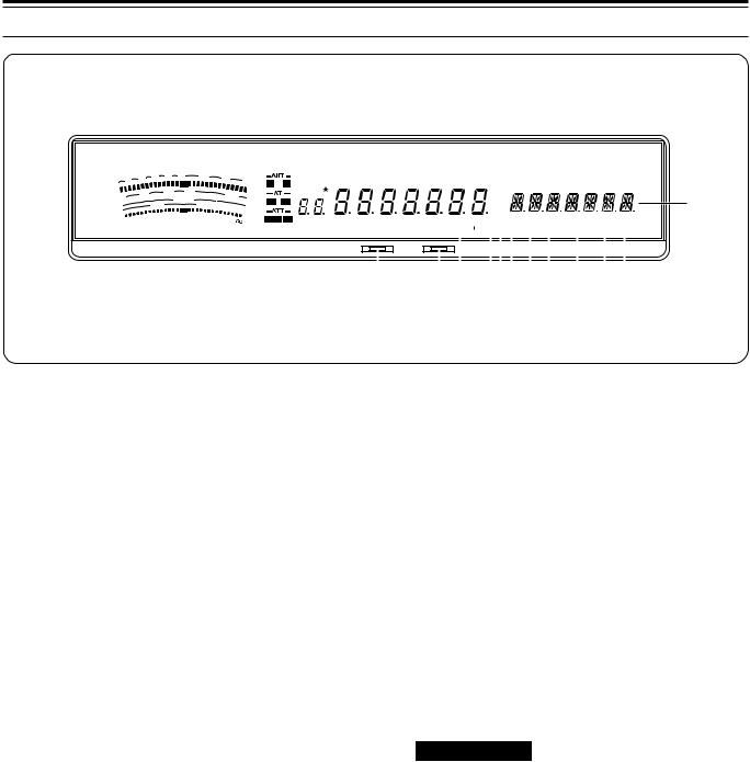
3 GETTING ACQUAINTED
|
|
1 |
3 |
5 |
7 |
9 |
20 |
40 |
60 d |
S |
|
|
|
|
|
||||
|
|
|
|
|
|
|
|||
|
|
|
|
25 |
|
|
|
B |
|
|
|
|
10 |
|
50 |
|
100 |
|
|
PWR |
0 |
|
|
|
FILTER |
|
W |
||
|
|
|
|
|
|
||||
|
|
|
|
ALC |
|
|
|
|
|
SWR |
|
1 |
1.5 |
|
10 2 |
3 |
20 |
|
d |
COMP |
|
|
|
|
|
|
|||
|
|
|
|
|
|
B |
|||
HF TRANSCEIVER |
TS-870 |
VOX FULL |
SEMI AIP AGC AUTO PROC |
MONI |
|
MENU |
SPLIT TONE NB |
|
CTRL |
||||||||||||||
M.CH |
|
|
|
|
|
|
|
|
A B |
RIT |
|
XIT |
|
WIDTH SHIFT |
|||||||
|
|
|
|
|
|
|
|
|
|
|
|
|
|
|
|
|
|
|
|
|
|
|
|
|
|
|
|
|
|
|
|||||||||||||
AUTO |
LSB USB CW R |
FSK FM AM |
M. SCR |
PRG |
SCAN |
F. LOCK |
FINE MHz |
||||||||||||||
|
|
|
|
|
|
|
|
|
|
|
|
|
|
|
|
|
|
|
|
|
|
|
|
|
|
|
|
|
|
|
|
|
|
|
|
|
|
|
|
|
|
|
|
ON AIR |
|
|
|
|
AT TUNE |
|
|
|
|
|
|
|
|
|
|
|
|
|
|
||
|
|
|
|
|
|
|
|
|
|
|
|
|
|
|
|
|
|
|
|
|
|
|
|
|
|
#4 |
#6 |
|
|
|
|
|
|
|
|
|
|
||||||
|
#2 |
#3 |
|
#5#7#8#9 $0 |
$1$2 |
||||||||||||||||
$3
#2ON AIR
Lights while the transceiver is in the transmit mode {page 23}.
#3AT TUNE
Lights while the internal antenna tuner is actually tuning for a correct match between the antenna system and the transceiver. Also lights while the transceiver is presetting the antenna tuner capacitors according to previously stored data {page 49}.
#4FSK
Lights while in Frequency Shift Keying (RTTY) mode {page 20}.
#5FM
Lights while in the FM operating mode {page 20}.
#6AM
Lights while in the AM operating mode {page 20}.
#7M.SCR
Lights while in Memory Scroll mode {page 56}.
#8PRG
Lights while Program Scan is activated {page 60} or memory channel 99 is selected {page 58}.
#9SCAN
Lights while a Scan function is activated {page 60}.
$0F.LOCK
Lights while the Lock function is ON {page 64}.
$1FINE
Lights while the Fine function is ON {page 21}.
$2MHz
Lights while the 1MHz Step {page 20} or Quick Menu {page 24} function is ON. Also lights while the Search function for programmed or vacant memory channels is ON {page 55}.
$3
Shows the Menu Items while accessing Menu mode {page 24}. Also shows frequency information (transmit, receive, or difference) while operating split frequency {page 42} and the RIT/XIT frequency offset if these functions are activated {pages 44, 45}.
18
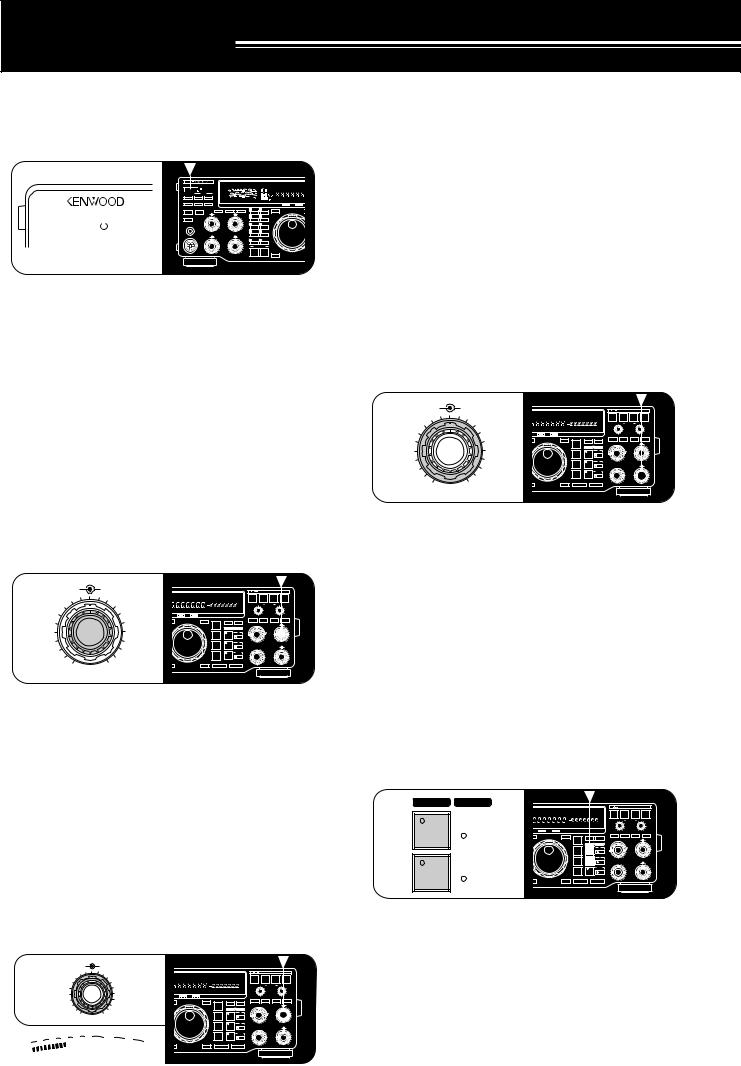
OPERATING BASICS
SWITCHING POWER ON/OFF
Switch ON the DC power supply, then press and hold down [ ] (POWER) until “HELLO” appears on the Display. Release [
 ] (POWER) when you see “HELLO”.
|
|
|
|
|
|
|
|
|
|
|
|
|
|
S |
|
|
40 |
|
60 dB |
|
VOX |
FULL |
SEMI AIP |
AGC |
AUTO |
PROC |
|
MONI |
|
|
|
|
|
|
|
|
|
|
|
|
|
|
|
|
|
|
|
||||||||||
|
|
|
|
|
|
|
|
|
|
|
|
|
|
|
|
|
|
|
||||||||||
|
|
|
|
|
|
|
|
|
|
|
|
|
|
|
|
|
|
|
||||||||||
|
|
|
|
|
|
|
|
|
|
|
ATT |
|
|
|
100 |
|
M.CH |
|
|
|
|
|
|
|
||||
|
|
|
|
|
|
|
|
|
|
|
|
|
|
|
|
|
|
|
|
|
|
|
|
|||||
|
|
|
|
|
|
|
|
|
ANT |
DOWN |
UP |
|
PWR |
|
|
|
|
W |
|
|
|
|
|
|
|
|
|
|
|
|
|
|
|
|
|
|
|
|
|
|
|
|
|
|
|
|
|
dB |
|
|
AUTO |
LSB |
USB CW |
R |
FSK FM |
|
AM |
|
|
|
|
|
|
|
|
|
VOX |
FULL/SEMI |
AIP |
|
|
|
|
|
|
|
|
|
|
|
|
|
|
|
|
|
|
|
|
|
|
|
|
|
|
|
|
|
|
|
HF TRANSCEIVER |
|
TS-870 |
|
|
|
ON AIR |
|
|
|
AT TUNE |
||||
|
|
|
|
|
|
|
|
|
AT TUNE |
THRU/AUTO |
|
METER |
PROC |
MONI |
1 |
|
CH 1 |
6 |
M.IN |
|
|
|
|
|
|
|
||
|
|
|
|
|
|
|
|
|
SEND |
|
|
AGC |
KEY SPEED |
PROC |
MONI |
|
|
|
|
|
|
ENTER |
|
|
|
|
|
TF-SET |
|
|
|
|
|
|
|
|
|
|
|
|
|
4 |
6 |
2 |
|
CH 2 |
7 |
M>VFO |
|
|
|
|
|
||||
|
|
|
|
|
|
|
|
|
|
|
|
|
|
2 |
8 |
3 |
|
CH 3 |
8 |
SCAN |
|
|
|
|
|
|
|
|
|
|
|
|
|
|
|
|
|
PHONES |
|
|
|
|
|
|
|
|
|
|
|
|
|
|
|
|
|
|
|
|
|
|
|
|
|
|
|
|
|
|
SLOW |
|
FAST |
|
|
|
|
|
|
|
|
|
|
|
|
|
|
|
|
|
|
|
|
|
|
|
|
|
|
|
OFF |
|
0 |
1 0 |
4 |
|
CH 4 |
9 |
CLR |
|
|
|
|
|
|
|
|
|
|
|
|
|
|
|
|
|
MIC |
|
|
CAR |
DELAY |
MIC |
PWR |
|
|
|
|
|
|
|
|
|
|
|
|
|
|
|
|
|
|
|
|
|
|
|
|
|
|
|
|
|
|
|
|
|
|
|
|
|
|||||
|
|
|
|
|
|
|
|
|
|
|
|
4 |
6 |
4 |
6 |
5 |
|
REC |
0 |
F.LOCK |
|
|
|
|
|
|
|
|
|
|
|
|
|
|
|
|
|
|
2 |
|
8 |
2 |
8 |
|
|
QUICK MEMO |
|
|
|
|
|
|
|
||||
|
|
|
|
|
|
|
|
|
|
|
|
|
|
|
|
|
|
|
|
|
|
FINE |
|
|
|
|
|
1MHz |
|
|
|
|
|
|
|
|
|
|
|
|
0 |
1 0 |
0 |
1 0 |
|
|
|
|
|
|
|
|
|
|
|
|
|
|
|
|
|
|
|
|
|
|
|
|
|
|
|
|
|
|
M.IN |
|
|
MR |
|
|
|
|
|
|
|
|
|
|
|
|
|
|
|
|
|
|
|
|
|
|
|
|
|
|
|
|
|
|
|
|
|
|
|
|
|
•After the “HELLO” message, the frequency and
other indicators light. Pressing [ ] (POWER) too long, switches the power OFF. If the TS-870S has not been used for an extended period, “HELLO” may not appear immediately.
To switch OFF the transceiver, press [ ] (POWER).
•After the transceiver has been switched ON, it can then be switched OFF or ON by using only the power switch on the DC power supply.
ADJUSTING VOLUME
AUDIO FREQUENCY (AF) GAIN
Turn the AF gain control clockwise to increase the audio level and counterclockwise to decrease the level.
AF |
RF |
|
|
|
|
|
|
|
|
|
|
|
|
|
|
|
|
|
4 |
6 |
FULL |
SEMI AIP |
AGC |
AUTO |
PROC |
MONI |
MENU |
SPLIT |
TONE |
NB |
CTRL |
|
AUTO |
BEAT |
|
|
|
|
|
|
|
|
|
|
|
A B |
RIT |
XIT |
WIDTH SHIFT |
|
NOTCH |
CANCEL |
N.R. |
|
TX EQ. |
|
<<<#6 (9L) >>> |
|
|
|
|
|
|
|
|
|
|
|
|
LO/WIDTH FILTER |
HI/SHIFT |
||||
AUTO |
LSB |
USB CW |
R |
FSK FM |
AM |
M. SCR |
PRG SCAN F. LOCK |
FINE MHz |
|
|
|
|
|
|
||||
ON AIR |
|
|
|
AT TUNE |
|
|
|
|
|
|
RIT |
XIT |
CLEAR |
NB |
||||
|
|
|
|
|
|
|
MODE |
|
|
A=B |
MENU |
|||||||
|
|
ENTER |
|
|
|
|
TF-SET |
LSB |
|
|
|
|
RIT/XIT |
|
AF |
RF |
||
|
|
|
|
|
|
|
|
|
|
|
|
|
4 |
6 |
||||
2 |
8 |
|
|
|
|
|
|
|
/USB |
|
|
RX |
TX |
|
|
|
|
|
|
|
|
|
|
|
|
|
|
|
|
A |
|
|
|
|
|
||
|
|
|
|
|
|
|
|
|
|
|
|
|
|
2 |
|
8 |
||
|
|
|
|
|
|
|
|
|
CW/– R |
|
|
|
|
|
|
|
|
|
|
|
|
|
|
|
|
|
|
|
|
|
|
B |
|
|
|
0 |
1 0 |
|
|
|
|
|
|
|
|
|
FSK |
|
|
|
|
M.CH/VFO.CH |
|
NB |
SQL |
|
|
|
|
|
|
|
|
|
|
/– R |
|
|
|
|
|
|
|
4 |
6 |
|
|
|
|
|
|
|
|
|
|
|
|
|
M.CH |
|
|
|
|
|
|
|
|
|
|
|
|
|
|
FM/AM |
|
|
|
|
|
2 |
|
8 |
|
|
|
FINE |
|
|
|
|
1MHz |
DOWN |
|
UP |
|
|
|
|
|
|||
|
|
|
|
|
|
|
|
|
|
|
|
|
|
|
|
|
0 |
1 0 |
01 0
Note: The position of the AF gain control does not affect the volume of “beeps” caused by pressing buttons nor the CW transmit sidetone. Also, the audio level for Packet operation is independent of the AF gain control setting.
RADIO FREQUENCY (RF) GAIN
Usually, set the RF gain control maximum clockwise. If you are having trouble hearing the desired signal due to excessive atmospheric noise or interference from other stations, it may help to reduce the RF gain.
To do this, take note of the peak S-meter reading of the desired signal, then turn the RF gain control counterclockwise to match this peak reading with the illuminated S-meter segments. Signals that are weaker than the level set with the RF gain control will be attenuated. Reception of the station is easier.
AF RF
46
|
|
|
|
|
|
|
|
|
|
FULL |
SEMI AIP |
AGC |
AUTO |
PROC |
MONI |
MENU |
SPLIT |
TONE |
NB |
CTRL |
AUTO |
BEAT |
|
|
|
|
|
|
|
|
|
|
|
|
|
|
|
|
|
|
|
A B |
RIT |
XIT |
WIDTH SHIFT |
NOTCH |
CANCEL |
N.R. |
|
TX EQ. |
|
|
|
|
|
|
|
|
|
|
|
|
|
|
|
|
|
|
|
|
|
|
LO/WIDTH FILTER |
HI/SHIFT |
|||
|
|
|
|
|
|
|
|
|
|
AUTO |
LSB |
USB CW |
R |
FSK FM |
AM |
M. SCR |
PRG SCAN F. LOCK |
FINE MHz |
|
|
|
|
|
||
|
|
|
2 |
|
|
|
8 |
|
|
ON AIR |
|
|
|
AT TUNE |
|
|
|
|
|
RIT |
XIT |
CLEAR |
NB |
||
|
|
|
|
|
|
|
|
|
|
|
|
|
|
|
|
|
|
|
|
|
|||||
|
|
|
|
|
|
|
|
|
|
|
|
|
|
|
|
|
MODE |
|
|
A=B |
MENU |
|
|
|
|
|
|
|
|
|
|
|
|
|
|
ENTER |
|
|
|
|
TF-SET |
LSB |
|
|
|
RIT/XIT |
|
AF |
RF |
||
|
|
|
|
|
|
|
|
|
|
|
|
|
|
|
|
|
|
|
|
4 |
6 |
||||
|
|
|
|
|
|
|
|
|
|
|
|
|
|
|
|
|
/USB |
|
|
RX |
TX |
|
|
|
|
|
|
|
|
|
|
|
|
|
|
|
|
|
|
|
|
|
|
|
|
|
A |
|
|
|
|
|
|
|
|
0 |
|
1 0 |
|
|
|
|
|
|
|
|
|
|
|
|
|
|
|
|
2 |
|
8 |
|
|
|
|
|
|
|
|
|
|
|
|
|
|
|
CW/– R |
|
|
|
|
|
|
|
|||
|
|
|
|
|
|
|
|
|
|
|
|
|
|
|
|
|
|
|
|
|
B |
|
|
0 |
1 0 |
|
|
|
|
|
|
|
|
|
|
|
|
|
|
|
|
|
FSK |
|
|
|
M.CH/VFO.CH |
|
NB |
SQL |
|
|
|
|
|
|
|
|
|
|
|
|
|
|
|
|
|
|
/– R |
|
|
|
|
|
|
4 |
6 |
|
|
|
|
|
9 |
20 |
|
|
|
|
|
|
|
|
|
|
|
|
|
|
M.CH |
|
|
|
|
|
1 |
3 |
5 |
7 |
40 |
60 d |
|
|
|
|
|
|
|
|
FM/AM |
|
|
|
|
2 |
|
8 |
|||
S |
|
|
|
|
|
|
B |
FINE |
|
|
|
|
1MHz |
DOWN |
|
UP |
|
|
0 |
1 0 |
|||||
|
|
|
|
|
|
|
|
|
|
|
|
|
|
||||||||||||
Furthermore, using a faster AGC setting {page 44} will help eliminate the blocking affect of the large AGC voltage that is developed due to a strong adjacent station.
Depending on the type and gain of your antenna, and the condition of the band, you may prefer leaving the RF gain control turned counterclockwise by some amount instead of turning it fully clockwise.
ADJUSTING SQUELCH
The purpose of squelch is to silence audio output from the speaker when no signals are present. Setting the squelch threshold too high causes the squelch to remain closed while a weak signal is present. Setting the threshold too low allows noise to be heard between transmissions from other stations. Many operators prefer leaving the squelch control fully counterclockwise unless operating full-carrier modes such as FM or AM.
NB |
SQL |
|
|
|
|
|
|
|
|
|
|
|
|
|
|
|
|
4 |
6 |
FULL |
SEMI AIP |
AGC |
AUTO |
PROC |
MONI |
MENU |
SPLIT |
TONE |
NB |
CTRL |
AUTO |
BEAT |
|
|
|
|
|
|
|
|
|
|
|
A B |
RIT |
XIT |
WIDTH SHIFT |
NOTCH |
CANCEL |
N.R. |
|
TX EQ. |
|
|
|
|
|
|
|
|
|
|
|
|
|
|
LO/WIDTH FILTER |
HI/SHIFT |
|||
|
|
AUTO |
LSB |
USB CW |
R |
FSK FM |
AM |
M. SCR |
PRG SCAN F. LOCK |
FINE MHz |
|
|
|
|
|
||
|
|
ON AIR |
|
|
|
AT TUNE |
|
|
|
|
|
RIT |
XIT |
CLEAR |
NB |
||
|
|
|
|
|
|
|
|
|
|
|
|
|
|||||
|
|
|
|
|
|
|
|
|
MODE |
|
|
A=B |
MENU |
|
|
|
|
|
|
ENTER |
|
|
|
|
TF-SET |
LSB |
|
|
|
RIT/XIT |
|
AF |
RF |
||
|
|
|
|
|
|
|
|
|
|
|
|
4 |
6 |
||||
2 |
|
8 |
|
|
|
|
|
|
/USB |
|
|
RX |
TX |
|
|
|
|
|
|
|
|
|
|
|
|
|
|
|
A |
|
|
|
|
||
|
|
|
|
|
|
|
|
|
|
|
|
|
2 |
|
8 |
||
|
|
|
|
|
|
|
|
|
CW/– R |
|
|
|
|
|
|
|
|
|
|
|
|
|
|
|
|
|
|
|
|
|
B |
|
|
0 |
1 0 |
|
|
|
|
|
|
|
|
|
FSK |
|
|
|
M.CH/VFO.CH |
|
NB |
SQL |
|
|
|
|
|
|
|
|
|
|
/– R |
|
|
|
|
|
|
4 |
6 |
|
|
|
|
|
|
|
|
|
|
|
|
|
M.CH |
|
|
|
|
|
|
|
|
|
|
|
|
|
FM/AM |
|
|
|
|
2 |
|
8 |
|
|
|
FINE |
|
|
|
|
1MHz |
DOWN |
|
UP |
|
|
|
|
|||
0 |
1 0 |
|
|
|
|
|
|
|
|
|
|
|
|
|
|
0 |
1 0 |
|
|
|
|
|
|
|
|
|
|
|
|
|
|
|
|
||
Turn the SQL control to just eliminate the background noise when no signal is present, or set and forget at full counterclockwise rotation.
DUAL DIGITAL VFOs
The A and B VFOs function independently so that different or the same frequencies can be selected by each VFO. The following sections explain how to select a VFO and how to copy frequency data from one VFO to the other.
SELECTING VFOs ([RX A], [RX B])
Press [RX A] to select VFO A. Press [RX B] to select VFO B.
RX TX
|
|
|
FULL |
SEMI AIP |
AGC |
AUTO |
PROC |
MONI |
MENU |
SPLIT |
TONE |
NB |
CTRL |
AUTO |
BEAT |
|
|
|
|
|
|
|
|
|
|
|
|
|
A B |
RIT |
XIT |
WIDTH SHIFT |
NOTCH |
CANCEL |
N.R. |
|
TX EQ. |
||
|
A |
|
|
|
|
|
|
|
|
|
|
|
LO/WIDTH |
FILTER |
HI/SHIFT |
||||
|
|
|
AUTO |
LSB |
USB CW |
R |
FSK FM |
AM |
M. SCR |
PRG SCAN F. LOCK |
FINE MHz |
|
|
|
|
|
|
||
|
|
|
ON AIR |
|
|
|
AT TUNE |
|
|
|
|
|
RIT |
XIT |
|
CLEAR |
NB |
||
|
|
|
|
|
|
|
|
|
|
MODE |
|
|
A=B |
MENU |
|
|
|
|
|
|
|
|
ENTER |
|
|
|
|
TF-SET |
LSB |
|
|
|
RIT/XIT |
|
|
AF |
RF |
||
|
|
|
|
|
|
|
|
|
|
|
|
|
|
|
|
|
4 |
6 |
|
|
|
|
|
|
|
|
|
|
|
/USB |
|
|
RX |
TX |
|
|
|
|
|
|
|
|
|
|
|
|
|
|
|
|
|
|
|
A |
|
|
|
|
|
|
|
|
|
|
|
|
|
|
|
|
|
|
|
|
|
|
2 |
|
8 |
|
|
|
|
|
|
|
|
|
|
CW/– R |
|
|
|
|
|
|
|
|
|
|
B |
|
|
|
|
|
|
|
|
|
|
|
|
B |
|
|
|
0 |
1 0 |
|
|
|
|
|
|
|
|
|
FSK |
|
|
|
M.CH/VFO.CH |
|
|
NB |
SQL |
||
|
|
|
|
|
|
|
|
|
|
/– R |
|
|
|
|
|
|
|
4 |
6 |
|
|
|
|
|
|
|
|
|
|
FM/AM |
|
|
M.CH |
|
|
2 |
|
8 |
|
|
|
|
FINE |
|
|
|
|
1MHz |
DOWN |
|
UP |
|
|
|
|
|
|||
|
|
|
|
|
|
|
|
|
|
|
|
|
|
|
|
|
|
0 |
1 0 |
|
|
|
|
|
|
|
|
|
|
|
|
|
|
|
|
|
|
|
|
|
|
|
|
|
|
|
|
|
|
|
|
|
|
|
|
|
|
|
|
1 Assume that you are presently using VFO A.
2 Press [RX B].
•VFO B is selected and the frequency currently selected by VFO B is displayed.
3 Press [RX A] to select VFO A again.
19
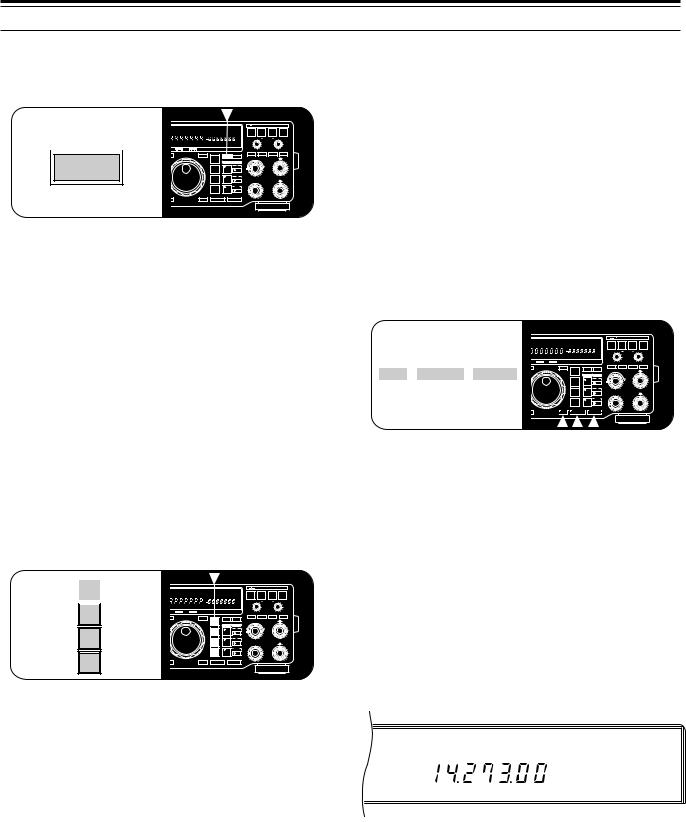
4 OPERATING BASICS
EQUALIZING VFO FREQUENCIES ([A=B]) |
SELECTING FREQUENCY |
Press [A=B] to transfer the frequency and modulation mode of the active VFO to the inactive VFO.
There are two methods to select a frequency that are explained in the following sections:
A Manual Tuning
|
FULL |
SEMI AIP |
AGC |
AUTO |
PROC |
MONI |
MENU |
SPLIT TONE NB |
CTRL |
AUTO |
BEAT |
|
|
|
|
||
A=B |
|
|
|
|
|
|
A B |
RIT |
XIT |
WIDTH SHIFT |
NOTCH |
CANCEL |
N.R. |
|
TX EQ. |
||
|
|
|
|
|
|
|
|
|
|
|
LO/WIDTH |
FILTER |
HI/SHIFT |
||||
AUTO |
LSB |
USB CW |
R |
FSK FM |
AM |
M. SCR |
PRG |
SCAN |
F. LOCK |
FINE MHz |
|
|
|
|
|
|
|
ON AIR |
|
|
|
AT TUNE |
|
|
|
|
|
RIT |
XIT |
|
CLEAR |
NB |
|||
|
|
MODE |
A=B |
MENU |
|
|
ENTER |
TF-SET |
LSB |
|
RIT/XIT |
AF |
RF |
|
|
4 |
6 |
|||
|
|
/USB |
RX |
TX |
|
|
|
A |
|
|
|
2 |
|
8 |
CW/– R |
|
|
|
|
B |
0 |
1 0 |
FSK |
M.CH/VFO.CH |
NB |
SQL |
/– R |
|
4 |
6 |
|
M.CH |
|
|
FM/AM |
2 |
|
8 |
|
|
|
FINE |
1MHz |
DOWN |
UP |
0 |
1 0 |
1 Assume that you are presently using VFO A.
2 Press [RX B].
•VFO B is selected and the frequency currently selected by VFO B is displayed.
3 Press [A=B].
4Press [RX A].
•This selects VFO A again. Note that the VFO B frequency and the modulation mode have been copied to VFO A due to Step 3.
SELECTING MODE
To change the operating mode, simply press the MODE button for the mode that you want to use. The second function on each MODE button is accessed by pressing the same button again.
Example: To switch to LSB, press [LSB/USB] one time. To then switch to USB, press [LSB/USB] again.
MODE
LSB |
|
|
|
|
|
|
|
|
|
|
|
|
|
|
|
/USB |
FULL |
SEMI AIP |
AGC |
AUTO |
PROC |
MONI |
MENU |
SPLIT TONE NB |
CTRL |
AUTO |
BEAT |
|
|
||
|
|
|
|
|
|
A B |
RIT |
XIT |
WIDTH SHIFT |
NOTCH |
CANCEL |
N.R. |
TX EQ. |
||
|
AUTO |
LSB |
USB CW |
R |
FSK FM |
AM |
M. SCR |
PRG |
SCAN |
F. LOCK |
FINE MHz |
LO/WIDTH FILTER |
HI/SHIFT |
||
|
|
|
|
|
|||||||||||
|
ON AIR |
AT TUNE |
|
|
RIT |
XIT |
CLEAR |
NB |
<<<#12 (9L) >>> |
|
|
MODE |
A=B |
MENU |
|
|
|
|
|
|
|
A |
|
AF4 |
RF6 |
|
CW/– R |
ENTER |
TF-SET |
LSB |
|
RIT/XIT |
|
||
|
|
|
/USB |
RX |
TX |
|
|
|
|
|
|
|
|
|
|
2 |
8 |
|
|
|
CW/– R |
|
|
|
|
|
FSK |
|
|
|
|
B |
|
0 |
1 0 |
|
|
FSK |
|
|
|
4 |
6 |
|
/– R |
|
|
/– R |
|
M.CH/VFO.CH |
|
||
|
|
|
|
|
NB |
SQL |
||
|
|
|
|
|
M.CH |
|
|
|
|
|
|
FM/AM |
|
|
|
2 |
8 |
|
|
|
|
|
|
|
|
FINE |
1MHz |
DOWN |
UP |
0 |
1 0 |
FM/AM
The CW mode defaults to the upper sideband. The “–R” label on [CW/–R] indicates that CW may be sent and received using the lower (reverse) sideband if you want. The “–R” label on [FSK/–R] indicates that the mark and space signals for RTTY may be reversed by selecting this mode.
In SSB mode, the transceiver automatically selects LSB for frequencies lower than 9.5 MHz, and selects USB for 9.5 MHz or higher frequencies if the Tuning control or Mic [UP]/[DWN] is used to cross the frequency of
9.5 MHz. This is also true if using the Front Panel [UP] or [DOWN] button.
Change to the correct band or use the 1MHz Step function to get close to the desired frequency. Then use the M.CH/VFO.CH control for coarse tuning and the Tuning control (or the Mic [UP] and [DWN] buttons) for selecting the exact frequency.
BDirect Frequency Entry (Keypad)
Enter the desired frequency directly using the numeric keypad.
CHANGING BANDS
|
|
|
|
|
FULL |
SEMI AIP |
AGC |
AUTO |
PROC |
MONI |
MENU |
SPLIT |
TONE |
NB |
|
CTRL |
|
AUTO |
BEAT |
|
|
|
|
|
|
|
|
|
|
|
|
|
|
|
A B |
RIT |
XIT |
WIDTH SHIFT |
|
NOTCH |
CANCEL |
N.R. |
|
TX EQ. |
|||
|
|
|
|
|
|
|
|
|
|
|
|
|
|
|
|
|
|
|
LO/WIDTH FILTER |
HI/SHIFT |
|||
|
|
|
|
|
AUTO |
LSB |
USB CW |
R |
FSK FM |
AM |
M. SCR |
PRG SCAN F. LOCK |
FINE MHz |
|
|
|
|
|
|
||||
1MHz |
|
DOWN |
|
UP |
ON AIR |
|
|
|
AT TUNE |
|
|
|
|
|
|
|
|
RIT |
XIT |
CLEAR |
NB |
||
|
|
|
|
|
|
|
|
|
|
|
|
|
|
|
|
||||||||
|
|
|
|
|
|
|
|
|
|
MODE |
|
|
A=B |
MENU |
|
|
|
|
|||||
|
|
|
|
|
ENTER |
|
|
|
|
TF-SET |
LSB |
|
|
|
|
|
RIT/XIT |
|
AF |
RF |
|||
|
|
|
|
|
|
|
|
|
|
|
|
|
|
|
|
|
4 |
6 |
|||||
|
|
|
|
|
|
|
|
|
|
|
|
|
/USB |
|
|
RX |
TX |
|
|
|
|
||
|
|
|
|
|
|
|
|
|
|
|
|
|
CW/– R |
|
|
|
A |
|
2 |
|
8 |
||
|
|
|
|
|
|
|
|
|
|
|
|
|
|
|
|
|
|
|
|
||||
|
|
|
|
|
|
|
|
|
|
|
|
|
|
|
|
|
|
|
|
|
|
||
|
|
|
|
|
|
|
|
|
|
|
|
|
|
|
|
|
|
B |
|
|
0 |
1 0 |
|
|
|
|
|
|
|
|
|
|
|
|
|
|
FSK |
|
|
|
|
|
M.CH/VFO.CH |
|
NB |
SQL |
|
|
|
|
|
|
|
|
|
|
|
|
|
|
/– R |
|
|
|
|
|
|
|
|
4 |
6 |
|
|
|
|
|
|
|
|
|
|
|
|
|
|
|
|
|
|
M.CH |
|
|
|
|
|
|
|
|
|
|
|
|
|
|
|
|
|
|
FM/AM |
|
|
|
|
|
|
2 |
|
8 |
|
|
|
|
|
|
|
|
|
|
|
|
|
|
|
|
|
|
|
|
|
|
|
||
|
|
|
|
|
FINE |
|
|
|
|
1MHz |
DOWN |
|
|
UP |
|
|
|
|
|||||
|
|
|
|
|
|
|
|
|
|
|
|
|
|
|
|
|
|
|
|
|
|
0 |
1 0 |
|
|
|
|
|
|
|
|
|
|
|
|
|
|
|
|
|
|
|
|
|
|
|
|
1If “MHz” is illuminated on the Display, first press [1MHz] to exit from the 1MHz Step mode.
• “MHz” goes out.
2Press [UP] or [DOWN].
•Holding down either button consecutively steps the transceiver to each band.
USING 1 MHz STEPS
The default step size for the 1MHz Step function is 1 MHz; however, you can also select 500 or 100 kHz
steps via Menu No. 52 (1M/500k). Menu selections are explained in more detail beginning on page 24.
1Press [1MHz] to enter the 1MHz mode.
• “MHz” lights.
AGC AUTO
USB |
MHz |
2Press [UP] or [DOWN].
•The frequency changes up or down in 1 MHz steps (or 500 or 100 kHz steps) each time [UP]or [DOWN] is pressed. Holding down either button causes the function to repeat.
20
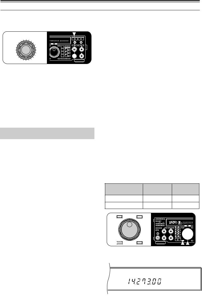
QUICK CHANGES
To move up or down in frequency quickly, use the
M.CH/VFO.CH control.
M.CH/VFO.CH
FULL |
SEMI AIP |
AGC |
AUTO |
PROC |
MONI |
MENU |
SPLIT |
TONE |
NB |
CTRL |
AUTO |
BEAT |
|
|
|
|
|
|
|
|
|
|
A B |
RIT |
XIT |
WIDTH SHIFT |
NOTCH |
CANCEL |
N.R. |
|
TX EQ. |
||
|
|
|
|
|
|
|
|
|
|
|
LO/WIDTH |
FILTER |
HI/SHIFT |
|||
AUTO |
LSB |
USB CW |
R |
FSK FM |
AM |
M. SCR |
PRG SCAN F. LOCK |
FINE MHz |
|
|
|
|
|
|
||
ON AIR |
|
|
|
AT TUNE |
|
|
|
|
|
RIT |
XIT |
|
CLEAR |
NB |
||
|
|
|
|
|
|
|
|
|
|
|
|
|||||
|
|
|
|
|
|
|
MODE |
|
|
A=B |
MENU |
|
|
|
|
|
ENTER |
|
|
|
|
TF-SET |
LSB |
|
|
|
RIT/XIT |
|
|
AF |
RF |
||
|
|
|
|
|
|
|
|
|
|
|
4 |
6 |
||||
|
|
|
|
|
|
|
/USB |
|
|
RX |
TX |
|
|
|
|
|
|
|
|
|
|
|
|
|
|
|
|
A |
|
|
|
|
|
|
|
|
|
|
|
|
|
|
|
|
|
|
|
2 |
|
8 |
|
|
|
|
|
|
|
CW/– R |
|
|
|
|
|
|
|
|
|
|
|
|
|
|
|
|
|
|
|
|
B |
|
|
|
0 |
1 0 |
|
|
|
|
|
|
|
FSK |
|
|
|
M.CH/VFO.CH |
|
|
NB |
SQL |
|
|
|
|
|
|
|
|
/– R |
|
|
|
|
|
|
|
4 |
6 |
|
|
|
|
|
|
|
|
|
|
|
M.CH |
|
|
|
|
|
|
|
|
|
|
|
|
FM/AM |
|
|
|
|
|
2 |
|
8 |
|
|
|
|
|
|
|
|
|
|
|
|
|
|
|
|
||
FINE |
|
|
|
|
1MHz |
DOWN |
|
UP |
|
|
|
|
|
|||
|
|
|
|
|
|
|
|
|
|
|
|
|
|
|
0 |
1 0 |
•Turn the M.CH/VFO.CH control clockwise to increase the frequency; counterclockwise to decrease the frequency.
Due to the large step sizes available, you can quickly move across the band. When the minimum or maximum receive frequency for the transceiver is reached, turning the M.CH/VFO.CH control will not decrease or increase respectively the frequency.
Menu No. 44 (STEP.ADJ) affects how the M.CH/VFO.CH control tunes. When Menu No. 44 is ON (default), rounding occurs on the first step (“click”) of the M.CH/VFO.CH control as shown below:
Step Adjust |
|
Channel Step |
Rounding Effect |
|
|||
(Menu No. 44) |
|
(Menu No. 43) |
|
|
|
||
ON |
|
10 kHz |
1 kHz, 100 Hz, and |
|
10 Hz digits change to 0. |
||
|
|
|
|
|
|
|
1 kHz digit changes to 0 |
ON |
|
5 kHz |
or 5, and 100 Hz and |
|
|
|
10 Hz digits change to 0. |
|
|
|
|
ON |
|
1 kHz |
100 Hz and 10 Hz digits |
|
change to 0. |
||
|
|
|
|
|
|
|
|
Example 1: Menu No. 44 (STEP.ADJ) is ON
•Menu No. 43 (CH. STEP): 10 kHz step size
•Selected frequency: 14.261.73 MHz
Turning the M.CH/VFO.CH control clockwise one step changes the frequency to 14.270.00 MHz, and one more step changes the frequency to 14.280.00 MHz. The rounding occurred on the first step.
Similarly, with 14.261.73 MHz selected, turning this control counterclockwise one step changes the frequency to 14.260.00 MHz, and one more step changes the frequency to 14.250.00 MHz. Again, the rounding took place on the first step.
Example 2: Menu No. 44 (STEP.ADJ) is OFF
•Menu No. 43 (CH. STEP): 10 kHz step size
•Selected frequency: 14.261.73 MHz
Turning the M.CH/VFO.CH control clockwise one step changes the frequency to 14.271.73 MHz, and one more step changes the frequency to 14.281.73 MHz. No rounding occurs.
With 14.261.73 MHz selected, turning this control counterclockwise one step changes the frequency to 14.251.73 MHz, and one more step changes the frequency to 14.241.73 MHz. Again, no rounding occurs.
4 OPERATING BASICS
■Changing Step Sizes
Select the step size that you prefer for the M.CH/VFO.CH control via Menu No. 43 (CH. STEP). Available step sizes are 1 kHz, 5 kHz and 10 kHz. The default is 10 kHz.
Within the AM broadcast band, the step size automatically defaults to 9 kHz (U.S.A./ Canada versions: 10 kHz) for the AM mode. This step size can be switched between 9 (ON) and 10 kHz (OFF) via Menu No. 42 (BC. STEP). Selecting OFF in Menu No. 42 allows you to use the step size specified via Menu No. 43 (1, 5, or 10 kHz). While in the AM broadcast band, changing the step size via Menu No. 42 will change the selected frequency to the nearest broadcast channel on the next use of the
M.CH/VFO.CH control.
If you enjoy listening to international shortwave broadcasters, the M.CH/VFO.CH control is also the best way to manually scan these bands. Select the 5 kHz step size via Menu No. 43 (CH. STEP) since most shortwave broadcasters are spaced 5 kHz apart. Set Menu No. 44 to ON. To listen to a broadcaster on a channel that is not a 5 kHz multiple, use the Tuning control to zero-in to the exact frequency.
FINE TUNING
For SSB, CW, and FSK modes, the Tuning control normally tunes through 10 kHz per revolution of the control. For FM and AM modes, one revolution of the Tuning control changes the frequency by 100 kHz. These tuning rates can be halved via Menu No. 41 (F.STEP).
In addition, the Fine Tuning function reduces the step size of the Tuning control further which allows you to tune more slowly and precisely.
Fine Tuning |
SSB/ CW/ FSK |
|
|
|
|
|
|
|
AM/ FM |
||||||
(Menu No. 41: 10 kHz) Tuning Steps |
|
|
Tuning Steps |
||||||||||||
OFF |
10 Hz |
|
|
|
|
|
|
|
|
100 Hz |
|||||
ON |
1 Hz |
|
|
|
|
|
|
|
|
|
10 Hz |
||||
ENTER |
TF-SET |
|
|
|
|
|
|
|
|
|
|
|
|
|
|
|
|
|
|
|
S |
|
|
40 |
|
60 dB |
|
VOX |
FULL |
SEMI AIP |
AGC AUTO PROC MONI |
|
|
ATT |
PWR |
|
|
100 |
W |
|
M.CH |
|
|
|
|||
|
ANT |
DOWN |
UP |
|
|
|
|
|
|
|
|
|
|||
|
|
|
|
|
|
|
|
|
|
dB |
|
|
AUTO |
LSB USB CW R FSK FM AM |
|
|
VOX |
FULL/SEMI |
AIP |
|
|
|
|
|
|
|
|
|
|
|
|
|
|
|
|
|
HF TRANSCEIVER |
|
TS-870 |
|
|
|
ON AIR |
AT TUNE |
|||
|
AT TUNE |
THRU/AUTO |
|
METER |
PROC |
MONI |
1 |
|
CH 1 |
6 |
M.IN |
|
|
|
|
|
SEND |
|
AGC |
KEY SPEED |
PROC |
MONI |
|
|
|
|
|
|
ENTER |
|
TF-SET |
|
|
|
|
4 |
6 |
2 |
|
CH 2 |
7 |
M>VFO |
|
||||
|
|
|
|
2 |
|
8 |
3 |
|
CH 3 |
8 |
SCAN |
|
|
|
|
|
PHONES |
|
|
|
|
|
|
|
|
|
|
|
|
|
|
|
|
SLOW |
|
FAST |
|
|
|
|
|
|
|
|
|
|
|
|
|
|
OFF |
|
0 |
1 0 |
4 |
|
CH 4 |
9 |
CLR |
|
|
|
|
|
MIC |
|
CAR |
DELAY |
MIC |
PWR |
|
|
|
|
|
|
|
|
|
|
|
|
4 |
6 |
4 |
6 |
5 |
|
REC |
0 F.LOCK |
|
|
|
||
|
|
2 |
|
8 2 |
|
8 |
|
|
QUICK MEMO |
|
|
|
|||
|
|
|
|
|
|
|
|
|
|
|
|
|
FINE |
|
1MHz |
FINE |
1MHz |
|
0 |
1 0 |
0 |
1 0 |
|
|
|
|
|
|
|
|
|
|
|
|
|
|
|
M.IN |
|
|
MR |
|
|
|
|||
Press [FINE].
•“FINE” lights.
AGC AUTO
USB |
FINE |
•The Fine Tuning function toggles ON and OFF each time [FINE] is pressed.
21
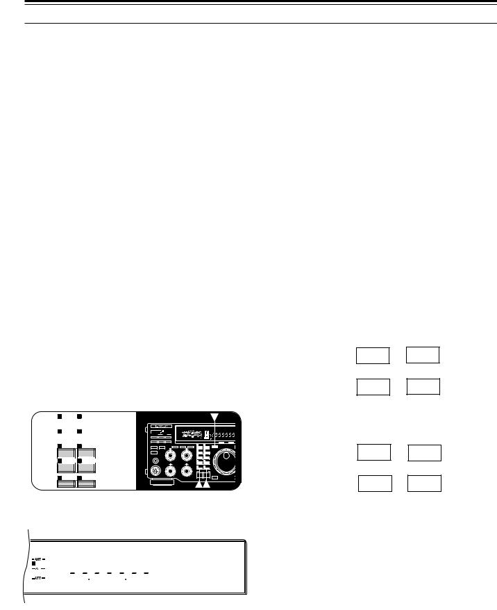
4 OPERATING BASICS
Note: After recalling memory channel 99 that has Start and End frequencies stored {page 58}, the receive frequency can be changed (like a VFO) by using the Tuning control.
DIRECT FREQUENCY ENTRY
Entering a frequency directly from the numeric keypad can be the fastest method to change to a specific frequency that is far removed from your current frequency.
The following points will help you enter a frequency correctly:
•Only the digits 0, 1, 2, or 3 can be entered for the 10 MHz digit (first digit). Pressing any digit 4 ~ 9 will cause the digit to be entered in the 1 MHz position. Therefore, to select a frequency of 3 MHz or lower, enter 0 for the 10 MHz digit.
•When the 10 Hz digit (last digit) is entered, the digit 0 is entered automatically for the 1 Hz digit, and frequency entry is completed. The 1 Hz digit is not displayed.
•If [ENTER] is pressed after beginning to enter digits, 0 is entered automatically for the remaining un-entered digits, and frequency entry is completed.
•Attempting to enter a frequency that is outside the TS-870S frequency range causes an alarm to be generated. The entered frequency is rejected.
•If an incorrect digit is pressed, restore the previous frequency by pressing [CLEAR], or [SEND], or Mic [PTT].
•When an entered frequency is accepted, RIT {page 44} and XIT {page 45} are switched OFF, but the RIT or XIT frequency is not changed.
1 |
CH 1 |
6 |
M.IN |
|
|
|
|
|
|
|
|
|
|
|
|
||
|
|
|
|
|
|
|
|
|
|
|
|
|
|
|
|
|
|
|
|
|
|
|
|
ENTER |
|
|
|
|
|
|
|
|
|
||
2 |
CH 2 |
7 |
M>VFO |
|
|
|
|
S |
|
60 dB |
|
|
|
||||
|
|
|
|
|
|
|
|
|
|
|
|
|
40 |
VOX |
FULL |
SEMI AIP |
AGC AUTO PROC MONI |
|
|
|
|
|
|
|
|
|
|
ATT |
|
PWR |
100 |
M.CH |
|
|
|
|
|
|
|
|
|
|
|
|
|
|
W |
|
|
|
|||
|
|
|
|
|
|
|
|
ANT |
DOWN |
UP |
|
|
dB |
AUTO |
LSB |
USB CW R FSK FM AM |
|
|
|
|
|
|
|
|
|
|
|
|
|
|
|
||||
|
|
|
|
|
|
|
|
VOX |
FULL/SEMI |
AIP |
|
|
|
|
|
|
|
|
|
|
|
|
|
|
|
|
|
|
|
HF TRANSCEIVER |
TS-870 |
|
ON AIR |
AT TUNE |
|
|
|
|
|
|
|
|
|
|
|
|
|
|
|
|
|
|
|
<<< (9L) >>> |
|
|
|
|
|
|
|
|
|
|
|
|||
3 |
CH 3 |
8 |
SCAN |
AT TUNE |
THRU/AUTO |
METER |
PROC |
MONI |
1 |
CH 1 |
6 |
M.IN |
|
|
|
|
|
|
SEND |
AGC |
KEY SPEED PROC |
MONI |
|
|
|
|
ENTER |
TF-SET |
|
|
|
|
|
|
|
4 |
6 |
2 |
CH 2 |
7 |
M>VFO |
|||
|
|
|
|
|
|
|
|
2 |
8 |
3 |
CH 3 |
8 |
SCAN |
|
|
|
|
|
PHONES |
SLOW |
FAST |
|
|
|
|
|
|
4 |
CH 4 9 |
CLR |
|
|
|
|
|
|
|||||
OFF |
|
0 |
1 0 |
4 |
CH 4 |
9 |
CLR |
||||||
|
|
|
|
|
MIC |
CAR4 |
DELAY6 |
MIC4 |
PWR6 |
|
|
|
|
|
|
|
|
|
|
|
|
|
|||||
|
|
|
5 |
REC |
0 F.LOCK |
2 |
8 |
2 |
8 |
QUICK MEMO |
|
FINE |
1MHz |
5 |
0 |
1 0 |
0 |
1 0 |
REC 0 F.LOCK |
|
|
M.IN MR |
1Press [ENTER].
• “– – . – – – . – –” appears.
AGC AUTO
USB
2Press the numeric buttons [0] ~ [9] to enter the frequency you desire.
•The transceiver changes to the entered frequency after the 10 Hz digit is pressed.
Note: After recalling memory channel 99 that has Start and End frequencies stored {page 58}, the receive frequency can be changed by using Direct Frequency Entry. When using the keypad to directly enter a frequency, you can never enter a frequency outside the frequency range programmed in memory channel 99.
FRONT PANEL METER
The multifunction meter measures the parameters in the following table. Peak readings for the S-meter, ALC, SWR, COMP, and PWR functions are held for approximately 2.5 seconds if Menu No. 09 (P HOLD) is ON.
Scale |
Displays |
Functional |
|
Condition |
|||
|
|
||
S |
Received signal strength |
Receive |
|
|
|
|
|
RX |
Width and shift of the |
Receive; |
|
FILTER |
receive pass band |
or Transmit plus |
|
|
|
[METER] ON |
|
|
|
|
|
PWR |
Transmit output power |
Transmit |
|
|
|
|
|
ALC |
Automatic level control |
Transmit plus |
|
|
status |
[METER] ON |
|
|
|
|
|
SWR |
Antenna system |
Transmit plus |
|
|
standing wave ratio |
[METER] ON |
|
|
|
|
|
COMP |
Speech compression |
Transmit plus |
|
|
when using the Speech |
SSB/AM plus |
|
|
Processor |
[PROC] ON plus |
|
|
|
[METER] ON |
|
|
|
|
Pressing the [METER] button cycles through the functions as shown below:
Receive Mode: SWR \ ALC
c d
OFF b COMP
Note: While receiving, the scales for the S-meter and the receive pass band function are always visible.
Transmit Mode: SWR \ ALC
c d
Receive b COMP pass band
Note:
While transmitting, the transmit power meter is always visible.
The COMP meter functions only when the Speech Processor is ON in SSB or AM mode.
22
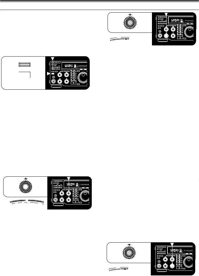
TRANSMITTING
Methods for transmitting include the following:
•Press [SEND].
•Press and hold down Microphone [PTT].
•Connect a key or keyer paddle, select the CW mode, press [VOX] to switch ON the Break-in function, and close the key or keyer paddle.
VOX |
|
|
|
|
|
|
|
|
|
|
|
|
|
|
|
|
|
40 |
VOX |
FULL |
SEMI AIP |
AGC |
AUTO |
PROC |
MONI |
||
|
|
|
S |
|
60 dB |
|
|
|
|
|
|
|
|
|
ATT |
|
PWR |
100 |
M.CH |
|
|
|
|
|
|
|
|
ANT |
DOWN |
UP |
|
W |
|
|
|
|
|
|
|
|
|
|
|
|
|
|
dB |
AUTO |
LSB |
USB |
CW |
R |
FSK |
FM |
AM |
VOX |
FULL/SEMI |
AIP |
|
|
|
|
|
|
|
|
|
|
|
|
AT TUNE |
|
|
|
HF TRANSCEIVER |
|
TS-870 |
|
|
ON AIR |
AT TUNE |
||
|
|
|
|
|
|
|
|
|
|
|
|
||
<<< |
(9L) >>> |
AT TUNE |
THRU/AUTO |
METER |
PROC |
MONI |
1 |
CH 1 |
6 |
M.IN |
|
|
|
SEND |
AGC |
KEY SPEED |
PROC |
MONI |
|
|
|
|
ENTER |
TF-SET |
|||
|
|
|
|
|
4 |
6 |
2 |
CH 2 |
7 |
M>VFO |
|
|
|
|
|
|
|
|
|
2 |
8 |
3 |
CH 3 |
8 |
SCAN |
|
|
|
|
|
PHONES |
|
|
|
|
|
|
|
|
|
|
|
|
|
|
SLOW |
FAST |
|
|
|
|
|
|
|
|
|
|
|
|
OFF |
|
0 |
1 0 |
4 |
CH 4 |
9 |
CLR |
|
|
|
SEND |
MIC |
CAR |
DELAY |
MIC |
PWR |
|
|
|
|
|
|
|
|
|
4 |
6 |
4 |
6 |
5 |
REC |
0 |
F.LOCK |
|
|
||
|
|
|
|
2 |
8 |
2 |
8 |
|
QUICK MEMO |
FINE |
1MHz |
||
|
|
|
|
|
|
|
|
|
|
|
|
||
|
|
|
|
0 |
1 0 |
0 |
1 0 |
|
|
|
|
|
|
|
|
|
|
|
|
|
|
|
M.IN |
|
MR |
|
|
|
|
|
|
|
|
|
|
|
|
|
|
|
|
Refer to sections in “COMMUNICATING” beginning on page 29 for detailed explanations for transmitting.
Note: You cannot transmit while the internal antenna tuner is presetting {page 49}.
SELECTING TRANSMIT POWER
It’s wise, and required by law, to select the lowest transmit power that allows reliable communication. Reducing power lowers the risk of interfering with others on the band. On the TS-870S, it is possible to change output power while transmitting.
To change your output power, turn the PWR control counterclockwise to reduce power and clockwise to increase power. The PWR scale on the Front Panel meter provides an indication of your output power in watts while you are transmitting.
MIC PWR
46
|
|
|
|
40 |
VOX |
FULL |
SEMI AIP |
AGC |
AUTO |
PROC |
MONI |
|
|
|
S |
|
60 dB |
|
|
|
|
|
|
|
|
ATT |
PWR |
100 |
M.CH |
|
|
|
|
|
|
ANT |
DOWN |
UP |
|
W |
|
|
|
|
|
|
|
|
|
|
|
|
dB |
AUTO |
LSB |
USB CW |
R |
FSK FM |
AM |
2 |
8 |
VOX FULL/SEMI AIP |
HF TRANSCEIVER |
TS-870 |
ON AIR |
AT TUNE |
AT TUNE |
THRU/AUTO |
METER |
PROC |
MONI |
1 |
CH |
1 |
6 |
M.IN |
|
|
SEND |
AGC |
KEY SPEED |
PROC |
MONI |
|
|
|
|
|
ENTER |
TF-SET |
|
|
4 |
6 |
2 |
CH |
2 |
7 |
M>VFO |
|
|
0 |
1 0 |
|
PHONES |
|
|
2 |
8 |
3 |
CH 3 |
8 |
SCAN |
|
|
|
|
|
|
|
|
|
SLOW |
FAST |
|
|
|
|
|
|
|
|
|
|
|
|
|
|
OFF |
|
0 |
1 0 |
4 |
CH 4 |
9 |
CLR |
|
|
|
|
|
|
|
MIC |
CAR |
DELAY |
MIC |
PWR |
|
|
|
|
|
|
|
|
|
|
|
|
4 |
6 |
4 |
6 |
5 |
REC |
0 |
F.LOCK |
|
|
|
|
|
|
|
|
2 |
8 |
2 |
8 |
|
QUICK MEMO |
|
||
|
|
25 |
50 |
|
|
|
|
|
|
|
|
|
FINE |
1MHz |
|
|
10 |
100 |
|
0 |
1 0 |
0 |
1 0 |
|
|
|
|
|
|||
PWR |
|
|
|
|
|
|
M.IN |
|
MR |
|
|||||
0 |
|
|
|
|
W |
|
|
|
|
|
|
|
|
|
|
TRANSMIT CARRIER LEVEL
The CAR control must be used for adjusting the carrier level for CW, AM, and FSK modes. The control also adjusts the Speech Processor output level when this function is used in the SSB mode. In general, set the CAR control so that the ALC meter reads within the limits of the ALC zone. If the carrier level is set via the computer interface, the position of the CAR control on the Front Panel is ignored. After turning the CAR control, the control becomes active again.
4 OPERATING BASICS
CAR DELAY
46
|
|
|
|
|
|
|
S |
|
|
40 |
|
60 dB |
|
VOX |
FULL |
SEMI AIP |
AGC |
AUTO |
PROC |
MONI |
|
|
|
|
ATT |
|
PWR |
|
|
100 |
W |
|
M.CH |
|
|
|
|
|
|
||
|
|
|
ANT |
DOWN |
UP |
|
|
|
|
|
|
|
|
|
|
|
|
|
||
2 |
|
8 |
|
|
|
|
|
|
|
|
|
dB |
|
|
AUTO |
LSB |
USB CW |
R |
FSK FM |
AM |
|
|
|
VOX |
FULL/SEMI |
AIP |
|
|
|
|
|
|
|
|
|
|
|
|
|
|
|
|
|
|
|
|
|
|
HF TRANSCEIVER |
|
TS-870 |
|
|
|
ON AIR |
|
|
|
AT TUNE |
|||
|
|
|
AT TUNE |
THRU/AUTO |
|
METER |
PROC |
MONI |
1 |
|
CH 1 |
6 |
M.IN |
|
|
|
|
|
|
|
|
|
|
SEND |
|
AGC |
KEY SPEED |
PROC |
MONI |
|
|
|
|
|
|
ENTER |
|
|
|
|
TF-SET |
|
|
|
|
|
|
4 |
6 |
2 |
|
CH 2 |
7 |
M>VFO |
|
|
|
|
||||
0 |
1 0 |
|
PHONES |
|
|
|
2 |
8 |
3 |
|
CH 3 |
8 |
SCAN |
|
|
|
|
|
|
|
|
|
|
|
SLOW |
|
FAST |
|
|
|
|
|
|
|
|
|
|
|
|
|
|
|
|
|
|
|
OFF |
|
0 |
1 0 |
4 |
|
CH 4 |
9 |
CLR |
|
|
|
|
|
|
|
|
|
|
MIC |
|
CAR |
DELAY |
MIC |
PWR |
|
|
|
|
|
|
|
|
|
|
|
|
|
|
|
|
|
4 |
6 |
4 |
6 |
5 |
|
REC |
0 |
F.LOCK |
|
|
|
|
|
|
|
ALC |
|
|
|
2 |
|
8 |
2 |
8 |
|
|
QUICK MEMO |
|
|
|
|
|
|
|||
|
|
|
|
0 |
1 0 |
0 |
1 0 |
|
|
|
|
|
|
FINE |
|
|
|
|
1MHz |
|
|
|
|
|
|
|
|
|
|
|
M.IN |
|
|
MR |
|
|
|
|
|
|
|
For more specific procedures, refer to instructions for each mode in “COMMUNICATING” beginning on page 29.
|
Mode |
Adjust CAR Control? |
|
|
|
|
|
CW, AM, FSK |
Yes |
||
|
FM |
No |
|
|
(Carrier level is fixed) |
||
|
|
||
|
|
|
|
|
Speech |
Yes |
|
USB/ |
Processor ON |
||
|
|||
|
|
||
LSB |
Speech |
No |
|
|
Processor OFF |
||
|
|
||
|
|
|
|
MICROPHONE GAIN
The MIC gain control must be adjusted any time the SSB (LSB or USB) or AM mode is used without speech processing. Set the MIC gain control so that the ALC meter reads within the limits of the ALC zone at all times. When Speech Processing is used, the microphone gain is fixed as shown in the table below regardless of the MIC gain control setting.
|
Mode |
Microphone |
|
(Speech Processor ON) |
Gain Fixed |
||
|
|
|
|
|
Transmit |
–28 dB |
|
USB/ |
Equalizer ON |
||
|
|||
|
|
||
LSB |
Transmit |
–34 dB |
|
|
Equalizer OFF |
||
|
|
||
|
|
|
|
|
AM |
–34 dB |
|
|
|
|
|
The MIC gain control has no affect in FM mode. Menu No. 61 (FM MIC) switches the microphone gain between low (L) and high (H) in this mode.
Refer to specific procedures in “COMMUNICATING” beginning on page 29.
MIC PWR
46
|
|
|
|
|
|
|
S |
|
|
40 |
|
60 dB |
|
VOX |
FULL |
SEMI AIP |
AGC |
AUTO |
PROC |
MONI |
|
|
|
|
ATT |
|
PWR |
|
|
100 |
W |
|
M.CH |
|
|
|
|
|
|
||
|
|
|
ANT |
DOWN |
UP |
|
|
|
|
|
|
|
|
|
|
|
|
|
||
2 |
|
8 |
|
|
|
|
|
|
|
|
|
dB |
|
|
AUTO |
LSB |
USB CW |
R |
FSK FM |
AM |
|
VOX |
FULL/SEMI |
AIP |
|
|
|
|
|
|
|
|
|
|
|
|
|
|
|
||
|
|
|
|
|
|
|
HF TRANSCEIVER |
|
TS-870 |
|
|
|
ON AIR |
|
|
|
AT TUNE |
|||
|
|
|
AT TUNE |
THRU/AUTO |
|
METER |
PROC |
MONI |
1 |
|
CH 1 |
6 |
M.IN |
|
|
|
|
|
|
|
|
|
|
SEND |
|
AGC |
KEY SPEED |
PROC |
MONI |
|
|
|
|
|
|
ENTER |
|
|
|
|
TF-SET |
|
|
|
|
|
|
4 |
6 |
2 |
|
CH 2 |
7 |
M>VFO |
|
|
|
|
||||
0 |
1 0 |
|
PHONES |
|
|
|
2 |
8 |
3 |
|
CH 3 |
8 |
SCAN |
|
|
|
|
|
|
|
|
|
|
|
SLOW |
|
FAST |
|
|
|
|
|
|
|
|
|
|
|
|
|
|
|
|
|
|
|
OFF |
|
0 |
1 0 |
4 |
|
CH 4 |
9 |
CLR |
|
|
|
|
|
|
|
|
|
|
MIC |
|
CAR |
DELAY |
MIC |
PWR |
|
|
|
|
|
|
|
|
|
|
|
|
|
|
|
|
|
4 |
6 |
4 |
6 |
5 |
|
REC |
0 |
F.LOCK |
|
|
|
|
|
|
|
|
|
|
|
2 |
|
8 |
2 |
8 |
|
|
QUICK MEMO |
|
|
|
|
|
|
|||
ALC |
|
|
|
|
0 |
1 0 |
0 |
1 0 |
|
|
|
|
|
|
FINE |
|
|
|
|
1MHz |
|
|
|
|
|
|
|
|
|
|
M.IN |
|
|
MR |
|
|
|
|
|
|
|
23
MENU SETUP
WHAT IS A MENU?
Many functions on this transceiver are selected or configured via a software-controlled Menu instead of physical controls on the transceiver. Once familiar with the Menu system, you will appreciate the versatility it offers. No longer is the number and complexity of features restricted by the physical controls and switches on the Front Panel.
MENU ACCESS
The following procedure explains how to check or change any of the Menu items.
1 Press [MENU].
2Turn the M.CH/VFO.CH control to select the desired Menu No.
3Press [UP], or [DOWN], or Mic [UP], or Mic [DWN] to change the current selection for this Menu item.
4Press [MENU] or [CLR] to exit Menu mode.
•If the power is switched OFF before this step is completed, the selection just made will be canceled.
MENU A/ MENU B
The TS-870S has two menus. These menus are called Menu A and Menu B. The menus contain identical functions; however, each menu can be configured independently.
For example, you may enjoy two different kinds of operating activities but you like to configure the transceiver differently for each activity. Menu A could be configured with one set of transmit signal characteristics, DSP settings, programmable buttons, frequency steps, etc. Menu B could be configured completely differently. By switching from Menu A to Menu B, you could instantly change Menu configuration and button assignment to suit your current operating style. Or, two operators may share a single transceiver. By dedicating one Menu per operator, each would always enjoy the best configuration.
With a little thought, you can determine the best setups for each Menu for your personal situation. Once you’ve decided your strategy, select via Menu No. 00 (MENU.A/B) the Menu that you want to set up first. Then use the information in this chapter and on the referenced pages to configure your ultimate operating environments.
QUICK MENU FUNCTION
The Quick Menu function complements the Menu A/B selection capability by allowing you to create your own customized but abbreviated Menu. Copying Menu items to the Quick Menu has no effect on the Menu. You should add only those Menu items to the Quick Menu that you use frequently.
■Programming the Quick Menu
1 Press [MENU].
2 Turn the M.CH/VFO.CH control to select the desired Menu No.
3 To add the selected Menu item to the Quick Menu, press [M.IN].
•The star lights indicating that the item has been added to the Quick Menu.
AGC AUTO |
MENU |
|
|
A |
B |
•Each press of [M.IN] toggles the item into or out of the Quick Menu.
4 Press [MENU] or [CLR] to exit Menu mode.
■Using the Quick Menu
1 Press [MENU].
2 Press [1MHz].
• “MHz” lights.
AGC AUTO |
MENU |
||
|
A |
B |
|
MHz
3Turn the M.CH/VFO.CH control to select the desired Quick Menu No.
•If the Quick Menu has not been programmed yet (see previous section), then turning the M.CH/VFO.CH control causes an alarm to be emitted (either “CHECK” in Morse code or a triple beep).
4Press [UP], or [DOWN], or Mic [UP], or
Mic [DWN] to change the current selection for this Quick Menu item.
5Press [MENU] or [CLR] to exit Quick Menu mode.
TEMPORARY MENU RESETTING
This convenient function allows you to temporarily reset all Menu items to their factory default selections. This can be useful to verify whether a Menu setting is causing undesirable operation.
1Press [CLR]+[ ] to temporarily reset all Menu items to factory default values.
• The “MENU” indicator flashes.
2To change all Menu items back to your own programmed values, switch OFF the transceiver, then switch it back ON.
24
 Loading...