


VHF FM TRANSCEIVER
TK-7185
SERVICE MANUAL
ADDENDUM
5 Tone Version
Metallic cabinet
(A01-2194-11)
© 2008-9 PRINTED IN JA PAN
B51-8849-00 (N) PDF
Use this service manual together with the
following service manual.
• TK-7185 service manual (B51-8843-00)
Panel assy
(A62-1166-02)
Modular jack
(E58-0522-05)
Key top
(K29-9349-01)
CONTENTS
SYSTEM SET-UP ....................................................................................... 3
REALIGNMENT ......................................................................................... 4
INSTALLATION .......................................................................................... 7
ADJUSTMENT ........................................................................................ 15
TERMINAL FUNCTION ........................................................................... 25
This product complies with the RoHS directive for the European market.
This product uses Lead Free solder.

TK-7185
Document Copyrights
Copyright 2008 by Kenwood Corporation. All rights re-
served.
No part of this manual may be reproduced, translated,
distributed, or transmitted in any form or by any means,
electronic, mechanical, photocopying, recording, or otherwise, for any purpose without the prior written permission
of Kenwood.
Disclaimer
While every precaution has been taken in the preparation
of this manual, Kenwood assumes no responsibility for errors or omissions. Neither is any liability assumed for damages resulting from the use of the information contained
herein. Kenwood reserves the right to make changes to any
products herein at any time for improvement purposes.
Firmware Copyrights
The title to and ownership of copyrights for firmware
embedded in Kenwood product memories are reserved for
Kenwood Corporation. Any modifying, reverse engineering, copy, reproducing or disclosing on an Internet website
of the firmware is strictly prohibited without prior written
consent of Kenwood Corporation. Furthermore, any reselling, assigning or transferring of the fi rmware is also strictly
prohibited without embedding the firmware in Kenwood
product memories.
Note
You must use KPG-92D version 1.50 or later for this
transceiver. KPG-92D versions earlier than version 1.50 will
not work properly.
2
Merchandise received
Choose the type of transceiver
TK-7185
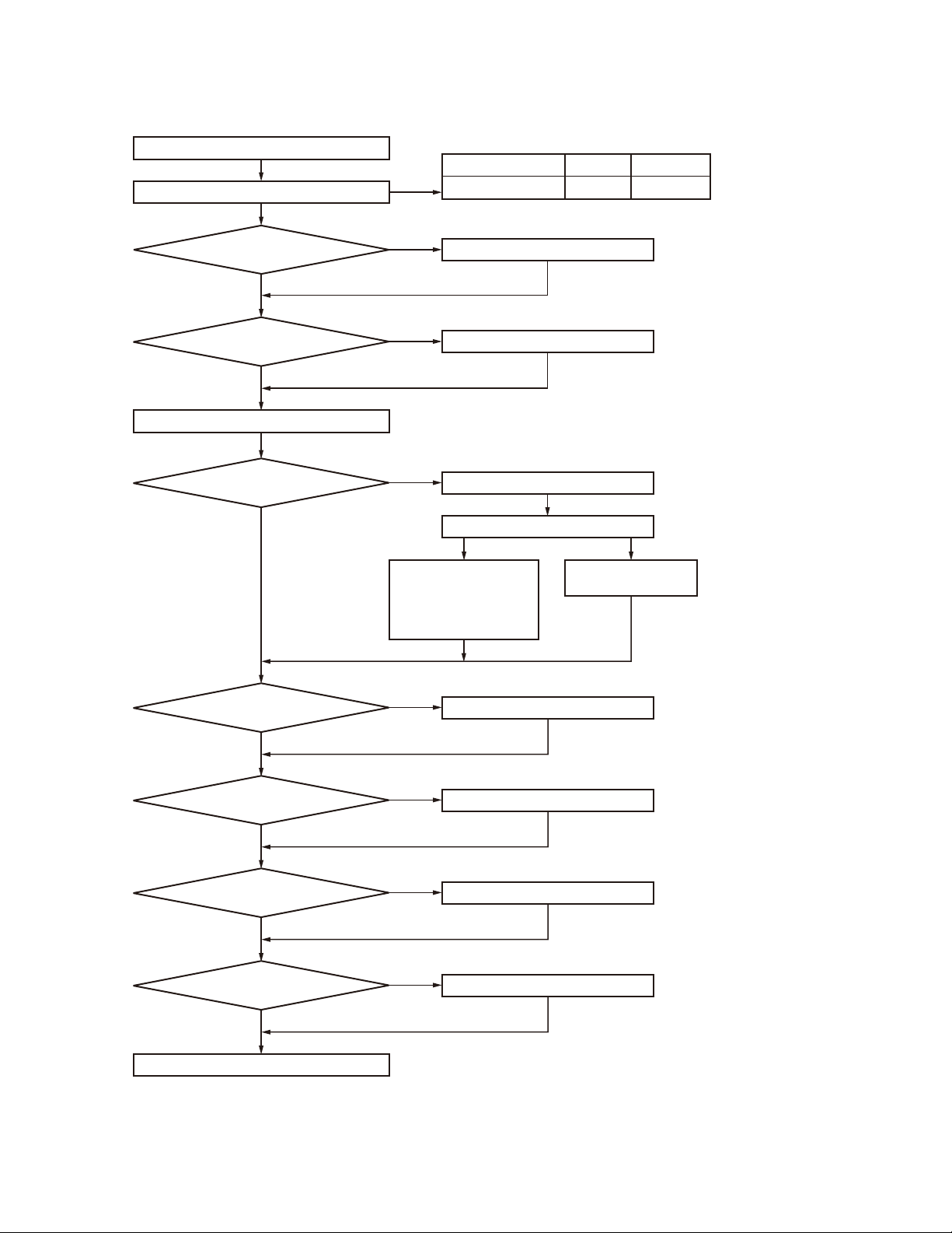
SYSTEM SET-UP
Frequency range RF power Type
217~270MHz 25W TK-7185 E
Are you using
the remote kit?
NO
Are you using
the ignition sense cable?
NO
Transceiver programming
Are you using
the radio interface cable?
NO
YES
YES
See page 4.
A personal computer (IBM PC or compatible), programming
interface (KPG-46/46A), and programming software (KPG-92D)
are required for programming.
YES
KCT-36 Extension cable
KGP-2A
Modem GPS receiver
or
KGP-2B
Modem GPS controller
KRK-10
KCT-46
KCT-40
(Option)
(Option)
(Option)
(Option)
or
KDS-100
Mobile data terminal
See page 9.
See page 7.
See page 7.
(Option)
(Option)
Are you using
the public address?
NO
Are you using
the voice guide & storage
unit?
NO
Are you using
the external speaker?
NO
Are you using
the keypad microphone?
NO
Delivery
YES
YES
YES
YES
KAP-2
(Option)
VGS-1
(Option)
KES-3 or KES-5 External speaker
(Option)
KMC-32 or KMC-36
(Option)
Desk top microphone KMC-9C
See page 8.
See page 10.
See page 11.
When the KAP-2 is installed
in the transceiver, the KES-5
can be installed.
3
TK-7185
REALIGNMENT
1. Modes
User mode
Panel test mode
PC mode
Firmware
programming mode
Clone mode
Firmware version information
Clock adjustment mode
Mode Function
User mode For normal use.
Panel test mode
Panel tuning mode Used by the dealer to tune the transceiver.
PC mode
Data programming
mode
PC test mode
PC tuning mode
Firmware programming mode
Clone mode
Firmware version
information
Clock adjustment
mode
Used by the dealer to check the fundamental characteristics.
Used for communication between the
transceiver and PC (IBM compatible).
Used to read and write frequency data and
other features to and from the transceiver.
Used to check the transceiver using the
PC. This feature is included in the FPU.
See panel test.
Used to tune the transceiver using the PC.
This feature is included in the FPU.
See panel tuning.
Used when changing the main program of
the fl ash memory.
Used to transfer programming data from
one transceiver to another.
Used to confi rm the internal fi rmware version.
Used by the dealer to adjust date and time.
Panel tuning mode
Data programming mode
PC test
mode
PC tuning
mode
3. Panel Test Mode
Setting method refer to ADJUSTMENT.
4. Panel Tuning Mode
Setting method refer to ADJUSTMENT.
5. PC Mode
5-1. Preface
The transceiver is programmed by using a personal computer, programming interface (KPG-46/46A), USB adapter
(KCT-53U) and programming software (KPG-92D).
The programming software can be used with a PC or
compatible. Figure 1 shows the setup of a PC for programming.
PC
D-SUB
(25-pin)
KPG-46
Transceiver
PC
KPG-92D
PC
D-SUB
(9-pin)
KPG-46A
Transceiver
Fig. 1
KPG-46 or KPG-46A or
KPG-46A + KCT-53U +
Tuning cable
(E30-3383-05)
PC
USB
KCT-53U
KPG-46A
Transceiver
2. How to Enter Each Mode
Mode Operation
User mode Power ON
Panel test mode [A] + Power ON
PC mode Received commands from PC
Panel tuning mode [Panel test mode] + [S]
Firmware programming mode [S] + Power ON
Clone mode [B] + Power ON
Firmware version information [
Clock adjustment mode [C] + Power ON
4
] + Power ON
5-2. Connection procedure
1. Connect the transceiver to the computer using the inter-
face cable and USB adapter (When the interface cable is
KPG-46A, the KCT-53U can be used.).
Notes:
• You must install the KCT-53U driver in the computer to
use the USB adapter (KCT-53U).
• When using the USB adapter (KCT-53U) for the fi rst time,
plug the KCT-53U into a USB port on the computer with
the computer power ON.

REALIGNMENT
TK-7185
2. When the POWER switch on, user mode can be entered
immediately. When PC sends command the transceiver
enter PC mode, and “PROGRAM” is displayed on the
LCD.
When data transmitting from transceiver, the red LED is
lights.
When data receiving to transceiver, the green LED is
lights.
Note:
The data stored in the computer must match the “Model
Name” when it is written into the fl ash memory.
5-3. KPG-46/KPG-46A description
(PC programming interface cable: Option)
The KPG-46/46A is required to interface the transceiver
to the computer. It has a circuit in its D-sub connector (KPG46: 25-pin, KPG-46A: 9-pin) case that converts the RS-232C
logic level to the TTL level.
The KPG-46/46A connects the 8-pin microphone connec-
tor of the transceiver to the RS-232C serial port of the computer.
5-4. KCT-53U description (USB adapter: Option)
The KCT-53U is a cable which connects the KPG-46A to
a USB port on a computer.
When using the KCT-53U, install the supplied CD-ROM
(with driver software) in the computer. The KCT-53U driver
runs under Windows 2000 or XP.
5-5. Programming software KPG-92D description
The KPG-92D is the programming software for the trans-
ceiver supplied on a CD-ROM. This software runs under
MS-Windows 98, Me, Windows 2000, XP or Vista (32-bit)
on an IBM-PC or compatible machine.
The data can be input to or read from the transceiver and
edited on the screen. The programmed or edited data can
be printed out. It is also possible to tune the transceiver.
6. Firmware Programming Mode
6-1. Preface
Flash memory is mounted on the transceiver. This al-
lows the transceiver to be upgraded when new features
are released in the future. (For details on how to obtain the
fi rmware, contact Customer Service.)
6-2. Connection procedure
Connect the transceiver to the personal computer (IBM
PC or compatible) using the interface cable (KPG-46/46A)
and USB adapter (KCT-53U: when the interface cable is
KPG-46A, the KCT-53U can be used.). (Connection is the
same as in the PC Mode.)
Note:
You can only program firmware from the 8-pin micro-
phone connector on the front panel. Using the 25-pin logic
interface on the rear panel will not work.
6-3. Programming
1. Start up the fi rmware programming software (Fpro.exe
(ver. 4.02 or later)). The Fpro.exe exists in the KPG-92D
installed holder.
2. Set the communications speed (normally, 115200 bps)
and communications port in the confi guration item.
3. Set the fi rmware to be updated by File name item.
4. Turn the transceiver power ON with the [S] key held
down. Then, the orange LED on the transceiver lights
and “PROG 115200” is displayed.
5. Check the connection between the transceiver and the
personal computer, and make sure that the transceiver is
in the Program mode.
6. Press write button in the window. When the transceiver
starts to receive data, the [PG] display is blinking.
7. If writing ends successfully, the checksum is calculated
and a result is displayed.
8. If you want to continue programming other transceivers,
repeat steps 4 to 7.
Note:
This mode cannot be entered if the Firmware Program-
ming mode is set to Disable in the Programming software.
6-4. Function
1. If you press the [■] key while “PROG 115200” is displayed, the display changes to “PROG 19200” (The
LED blinks green) to indicate that the write speed is
low speed (19200 bps). If you press the [■] key again
while “PROG 19200” is displayed, the display changes
to “PROG 38400” (The LED lights red and orange alternatively). If you press the [■] key again while “PROG
38400” is displayed, the display changes to “PROG
57600” (The LED blinks orange). If you press the [■]
key again while “PROG 57600” is displayed, the display
returns to “PROG 115200” (The LED lights orange).
2. If you press the [
played, the checksum is calculated, and a result is displayed. If you press the [
sum is displayed, “PROG 115200” is redisplayed.
] key while “PROG 115200” is dis-
] key again while the check-
Note:
Normally, write in the high-speed mode.
7. Clone Mode
Programming data can be transferred from one trans-
ceiver to another by connecting them via their 8-pin microphone connectors. The operation is as follows (the transmit
transceiver is the source and the receive transceiver is a
target).
The following data cannot be cloned.
• Tuning data
• Embedded message with password
• Model name data
5
TK-7185
REALIGNMENT
1. Turn the source transceiver power ON with the [B] key
held down. If the read authorization password is set to
the transceiver, the transceiver displays “CLONE LOCK”.
If the password is not set, the transceiver displays
“CLONE MODE”.
2. When you enter the correct password, and “CLONE
MODE” is displayed, the transceiver can be used as the
cloning source. The following describes how to enter the
password.
3.
•
How to enter the password with the microphone keypad;
If you press a key while “CLONE LOCK” is displayed,
the number that was pressed is displayed on the transceiver. Each press of the key shifts the display in order to
the left. When you enter the password and press the [
key, “CLONE MODE” is displayed if the entered password is correct. If the password is incorrect, “CLONE
LOCK” is redisplayed.
• How to enter the password with the [
If the [
is displayed, numbers (0 to 9) are displayed flashing.
When you press the [C] key, the currently selected number is determined. If you press the [S] key after entering
the password in this procedure, “CLONE MODE” is
displayed if the entered password is correct. If the password is incorrect, “CLONE LOCK” is redisplayed.
4. Power ON the target transceiver.
5. Connect the cloning cable (Part No. E30-3382-05) to the
modular microphone jacks on the source and target.
6. Press the [S] key on the source while the source displays
“CLONE MODE”. The data of the source is sent to the
target. While the target is receiving the data, “PROGRAM” is displayed. When cloning of data is completed,
the source displays “END”, and the target automatically
operates in the User mode. The target can then be operated by the same program as the source.
7. The other target can be continuously cloned. When the [S]
key on the source is pressed while the source displays
“END”, the source displays “CLONE MODE”. Carry out
the operation in step 4 to 6.
] and [ ] keys is pressed while “CLONE LOCK”
] and [ ] keys;
8. Firmware Version Information
Press and hold the [ ] key while turning the transceiver
power ON and then keep pressing and holding the [
the fi rmware version information appears on the LCD.
] key,
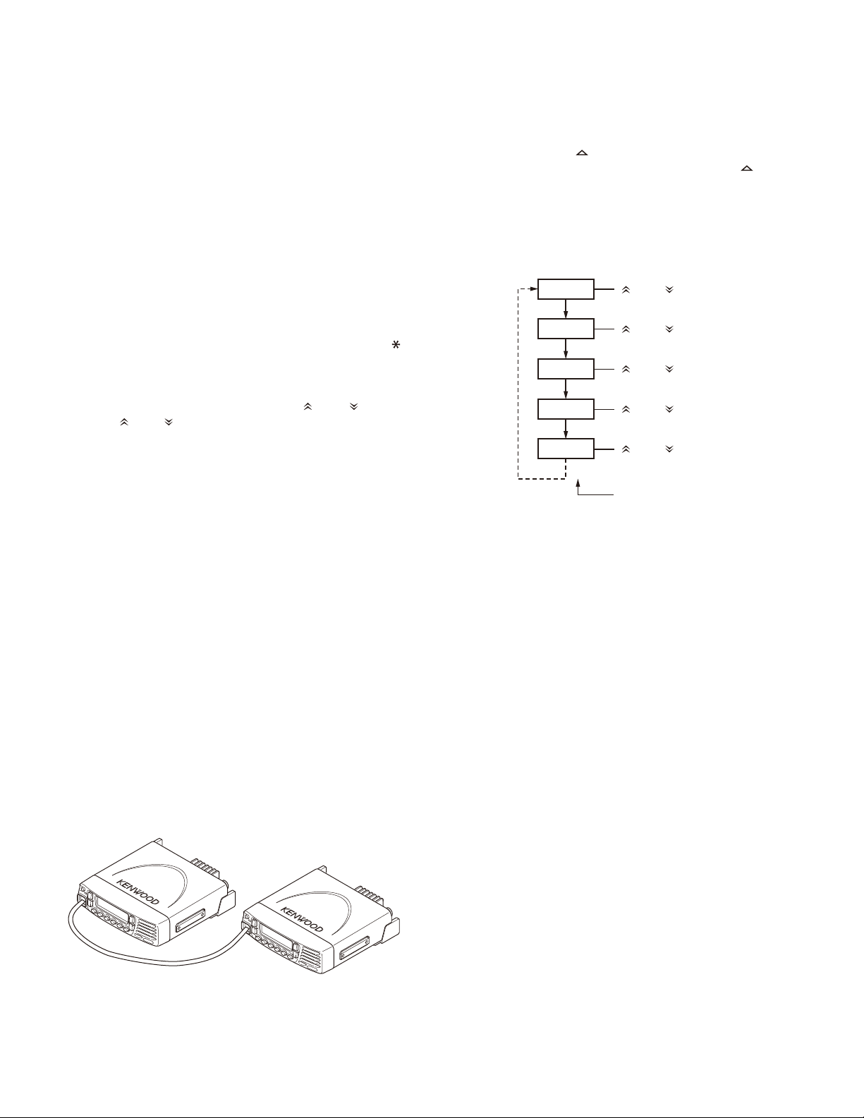
9. Clock Adjustment Mode
9-1. Flow chart of operation
[C] + Power ON
YEAR
[S]
MONTH
]
[S]
DAY
[S]
HOUR
[S]
MINUTE
[S]
[ ] and [ ] keys
[ ] and [ ] keys
[ ] and [ ] keys
[ ] and [ ] keys
[ ] and [ ] keys
Completion
Notes:
• Only the same models can be cloned together.
• Cannot be cloned if the overwrite password is programmed to the target.
Cloning cable
(E30-3382-05)
Fig. 2
6
INSTALLATION
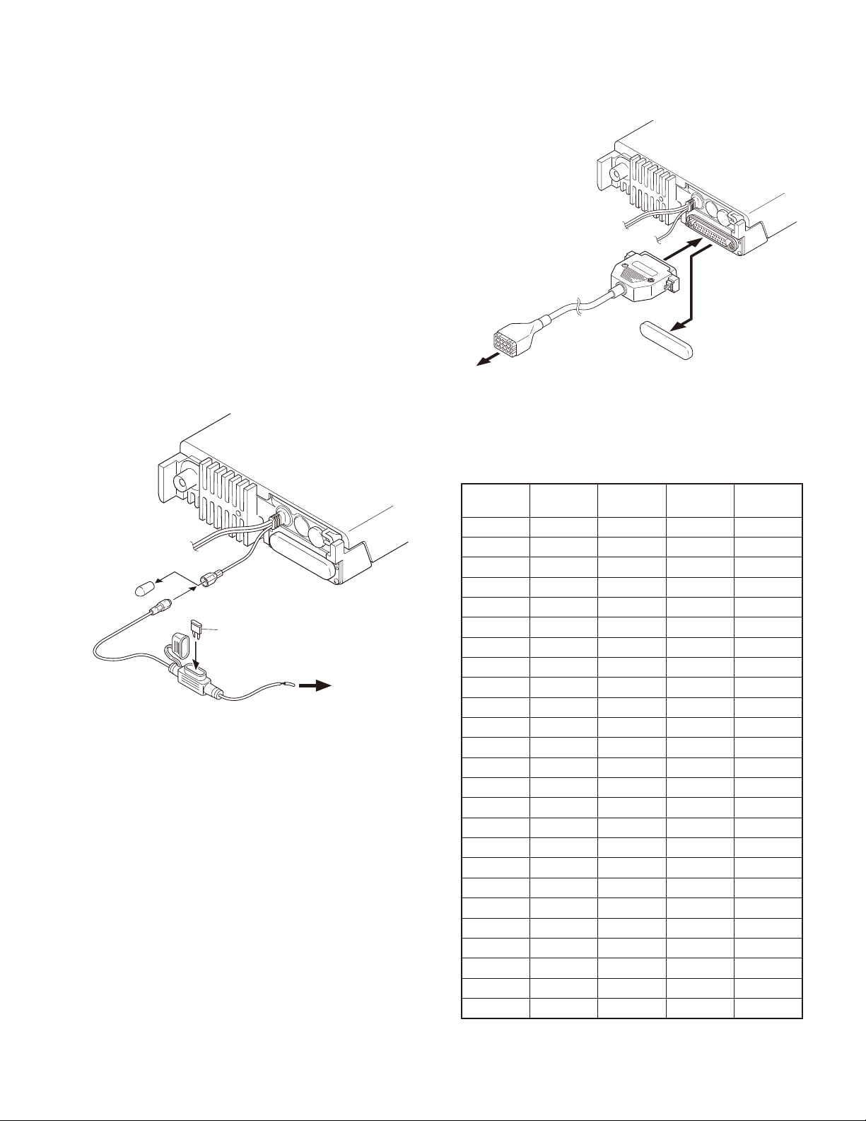
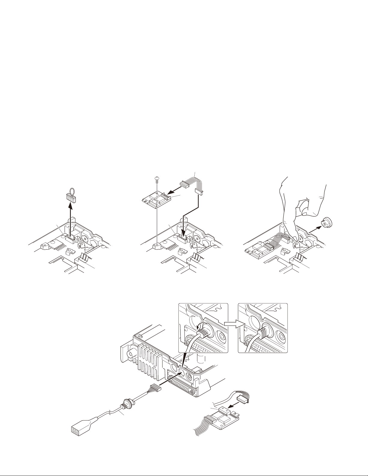
1. Ignition Sense Cable (KCT-46: Option)
The KCT-46 is an optional cable for enabling the ignition
function. The ignition function lets you turn the power to
the transceiver on and off with the car ignition key.
1-1.
Connecting the KCT-46 cable to the transceiver
1. Open the KCT-46 fuse holder and insert a mini blade fuse
(3A). (
2. While holding a clear protective cover, remove the black
cap at the end of the yellow cable (ignition sense cable)
of the transceiver. (
3. Connect the plug of the KCT-46 to the yellow cable ter-
minal of the transceiver. (
4. Connect the other end of the KCT-46 to the ignition line
of the car. (
Note: You must setup using the KPG-92D.
q
)
)
w
)
e
)
r
TK-7185
@
:
.
KDS-100, KGP-2A,
KGP-2B or through
KCT-36 extension cable
Fig. 2
@
.
F52-0019-05
:
;
Ignition line
of the car
Fig. 1
2. Radio Interface Cable (KCT-40: Option)
The KCT-40 connection cable kit is used to connect the
transceiver to the KDS-100 (Mobile data terminal), KGP-2A
(Modem GPS receiver), KGP-2B (Modem GPS controller) or
through the KCT-36 extension cable.
2-1.
Connecting the KCT-40 cable to the transceiver
1. Remove the D-sub cap on the rear of the transceiver. (
2. Connect the D-sub connector of the KCT-40 to the D-sub
25-pin terminal of the transceiver. (
3. Connect the 15-pin connector of the KCT-40 to a KDS-
100, KGP-2A, KGP-2B or through a KCT-36 extension
cable. (
Note: You must setup using the KPG-92D.
e
)
w
)
q
2-2. Terminal function
D-sub 25-pin
Pin No.
1----
2----
3----
4----
5 DI 5 DO DO
6----
7 GND 3 GND GND
8 AIO8 9 TXS/LOK TXS/LOK
9 TXD2 15 RXD RXD
10 RXD2 14 TXD TXD
11----
12 AIO7 11 MM MM
13 AIO6 6 PTT PTT
14 SB 1 SB SB
15----
16----
17----
18----
)
19 DEO 4 DI DI
20 AIO5 8 SQ SQ
21 AIO4 10 AM AM
22 AIO3 13 - DISP OFF
23 AIO2 12 - -
24 AIO1 7 DTC DTC
25----
TK-7185
Function
Molex 15-pin
Pin No.
KDS-100
Function
KGP-2A/2B
Function
7
TK-7185
INSTALLATION
3. Horn Alert/P.A. Relay Unit (KAP-2: Option)
The Horn alert (max. 2A drive), Public address and External speaker function are enabled by installing the KAP-2 in
the transceiver.
3-1. Installing the KAP-2 unit in the transceiver
(The kit A is not used in the KAP-2 accessories)
1. Remove the cabinet, top packing and shielding plate of
the transceiver.
2. Set the KAP-2 relay unit jumper pins according to the
purpose of use.
3. Remove the 6-pin jumper connector inserted in the TX-
RX unit (B/3) connector (CN428). (
4. Insert one side of the lead wire with connector (E37-
1114-05) into the relay unit connector (CN3) (
other side into the TX-RX unit (B/3) connector (CN428)
(
).
e
q
)
w
) and the
E37-1114-05
@
5. Place the relay unit at the position shown in Figure 3-2
and secure it to the chassis with a screw.
6. Remove the cap on the rear of the chassis by pushing it
from the inside with your fi nger. (
7. Pass the 6-pin connector of the cable (E37-1113-15)
through the chassis hole (
the chassis hole.
8. Rotate the bush of the cable 90 degrees counterclockwise as viewed from the rear of the chassis. (
9. Insert the 6-pin connector of the cable into the connector
(CN2) of the KAP-2 relay unit. (
Note: You must setup using the KPG-92D.
CN3
t
)
r
) and insert the bush into
)
y
)
u
.
:
CN428
CN428
Fig. 3-1 Fig. 3-2 Fig. 3-3
B
;
=
CN2
E37-1113-15
>
Fig. 3-4
8
INSTALLATION
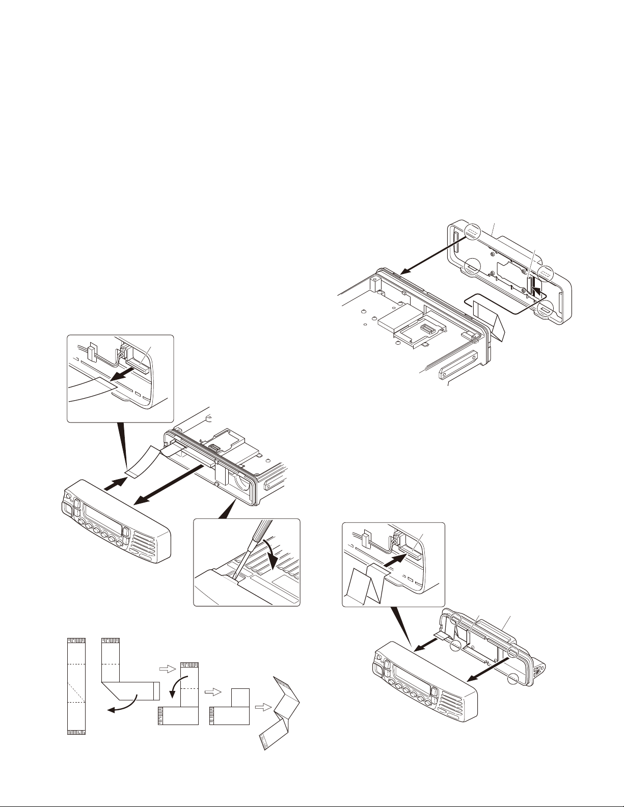
4. Control Head Remote Kit (KRK-10: Option)
The KRK-10 remote kit is used to remotely operate the
transceiver.
4-1. Installing the KRK-10 kit to the transceiver
1. Remove the front panel from the transceiver.
2. Install the KRK-10 main panel onto the transceiver.
3. Install the KRK-10 rear panel onto the front panel.
4. Connect the KRK-10 main panel to the rear panel with
the cable.
Remove the front panel from the transceiver
■
1. Lift the two tabs of the panel on the bottom of the transceiver with a fl at-head screwdriver (
panel from the chassis (
Note: Confi rm that the tabs of the speaker hardware fi x-
ture and holder is securely fi tted in the front panel.
2. Remove the fl at cable from the connector (CN902) of the
display unit of the panel. (
3. Fold the black line of the flat cable (in three parts) as
shown in Figure 4-2. ( r, t, y )
CN902
w
).
e
)
) and remove the
q
TK-7185
Install the KRK-10 main panel onto the transceiver
■
4. Insert the fl at cable that was removed in step 2 above
into the connector (CN1) of the interface unit (A/2) of the
KRK-10 main panel (A62-1101-11). (
Note: The terminal side of the fl at cable must face down
when inserting the fl at cable into the connector.
5. Fit the main panel with four tabs onto the front of the
chassis. (
Note: When installing the main panel onto the front of
the chassis, hold down the fl at cable with your fi ngers to
prevent it from being caught.
i
)
2
)
u
KRK-10 main panel
CN1
>
Chassis
side
B
;
;
.
@
Fig. 4-1
=
B
:
Fig. 4-3
Install the KRK-10 rear panel onto the front panel
■
6. Insert the fl at cable attached to the interface unit (B/2) of
the KRK-10 rear panel (A82-0056-21) into the connector
(CN902) of the display unit of the panel (
cable has been pre-inserted in the connector (CN2) of
the rear panel at the time of shipping.)
Note: The terminal side of the fl at cable must face down
when inserting the fl at cable into the connector.
7. Fit the four tabs of the rear panel into the front panel. (
CN902
). (The fl at
o
!0
8
KRK-10 rear panel
CN2
)
=
Panel
side
Fig. 4-4
Fig. 4-2
9
 Loading...