


KR-V5560
Table of contents
 Loading...
AUDIO VIDEO STEREO RECEIVER
KR-V5560
KR-694
INSTRUCTION MANUAL
KENWOOD CORPORATION
This manual contains instructions for two models.
For your records
Record the serial number, found on the back of the unit, in the spaces designated on the warranty
card, and in the space provided below. Refer to the model and serial numbers whenever you call
upon your dealer for information or service on this product.
Model____________________
_
________
Serial Number
_________________________________
Unpacking
Unpack the unit carefully and make sure that all accessories are put aside so they will not be lost.
Examine the .unit for.any possibility of shipping damage. If your unit is damaged or fails to operate,
notify your dealer immediately. If your unit was shipped to you directly, notify the shipping com
pany without delay. Only the consignee (the person or company receiving the unit) can file a claim
against the carrier for shipping damage.
We recommend that you retain the original carton and packing materials for use should you trans
port or ship the unit in the future.
Accessories
FM indoor antenna
.........
(1) AM loop antenna......................(1 ) Loop antena stand
...............
(1)
Except for
U,S,A,, Canada, Mexico
and Australia____
Remote control unit
...
....
(11 Batteries (R6/AA)
.................
(2)
oooooocoo
0000000 0
oocaoocro
□OCDOOOOO
B60-1453-00 CsD(K,P,M,X.Y.R) CmC;
aution: head this page carefuhv to ensure sa
ЪжпаатФП
Units are designed for operation as follows.
U.S.A. Mexico and Canada
___
__________________
J20 V only
Australia
...................
..........
.
..................
.
.................
only
Other countries...
..110-120/220-240 Vswitc
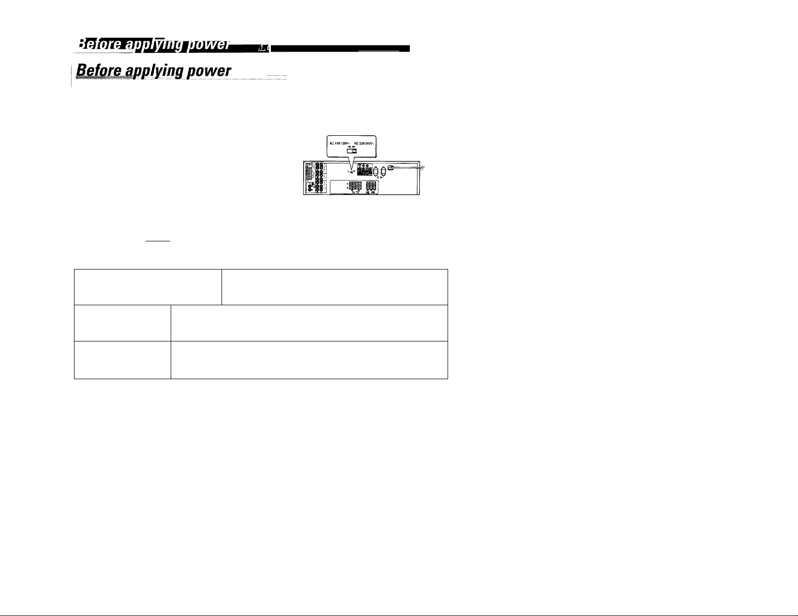
AC voitage sefection
This unit operates on 110 - 120 volts or 220 - 240 volts
AC. The AC voltage selector switciTon the rear panel is
set to the voltage that prevails in the area to which the
unit is shipped. Before connecting the power cord to your
AC outlet make sure that the setting position of this
switch matches your line voltage. If not, it must be set to
your voltage in accordance with the following direction.
Our warranty does not cover damage caused by excessive line volt
age due to improper setting of the AC Voltage selector switch.
AC voltage selector switch
Move switch lever to match your line voltage
with a small screwdriver or other pointed tool.
Mofeta precautions
WARNING
TO PREVENT FIRE OR ELECTRIC SHOCK, DO NOT EXPOSE THIS APPLIANCE TO RAIN
OR MOISTURE.
CAUTION; TO REDUCE THE RISK OF ELECTRIC SHOCK. DO NOT REMOVE COVER
[OR ВАСЮ. NOUSER-SERVICEABLEPARTSINSIDE, REFER SERVICING TO QUALIFIED
SERVICE PERSONNEL.
A
THE LIGHTNING FLASH WITH ARROWHEAD SYMBOL. WITHIN AN EQUILATERAL TRIANGLE, IS
INTENDED TO ALERT THE USER TO THE PRESENCE OF UNTNSULATED "DANGEROUS VOLTAGE"
WITHIN THE PRODUCT’S ENCLOSURE THAT MAY BE OF SUFFICIENT MAGNITUDE TO CONSTITUTE A
RISK OF ELECTRIC SHOCK TO PERSONS.
A
THE EXCLAMATION POINT WITHIN AN EQUILATERAL TRIANGLE IS INTENDED TO ALERTTHE USER TO
THE PRESENCE OF IMPORTANT OPERATING AND MAINTENANCE [SERVICING) INSTRUCTIONS IN THE
LITERATURE ACCOMPANYING THE APPLIANCE,
FortheU.S.A.
FCC WARNiNG
This equipment may generate or use radio frequency energy. Changes or modifications to this equipment may cause harmful interference
unless the modifications are expressly approved in the instruction manual. The user could lose the authority to operate this equipment if an
unauthorized change or modification is made.
NOTE:
This equipment has been tested and found to comply with the limits for a Class B digital device, pursuant to Part 15 of the FCC Rules. These
limits are designed to provide reasonable protection against harmful interference in a residential installation. This equipment may cause harmful
interference to radio communications, if it is not installed and used in accordance with the instructions. However, there is no guarantee that
interference will not occur in a particular installation. If this equipment does cause harmful interference to radio or television reception, which
can be determined by turning the equipment off and on, the user is encouraged to try to correct the interference by one or more of the following
measures: .
— Reorient or relocate the receiving antenna.
— Increase the separation between the equipment and receiver.
— Connect the equipment into an outlet on a circuit different from that to which the receiver is connected,
— Consult the dealer or an experienced radio / TV technician for help.
FortheU.S.A.
Note to CA TV system instaher:
This reminder is provided to call the CATV system installer's attention to Article 820-40 of the NEC that provides guidelines for proper
grounding and, in particular, specifies that the cable ground shall be connected to the grounding system of the building, as close to the point of
cable entry as practical.
SpecialJeatures
mmxmuQSULMmLimimL
The surround system reproduces vìdeo software programes
carrying the ixiioonYsunwotji«; mark with simifar acoustic effects
to movie theater.
The DOLBY PRO LOGIC made controls the audio signals of the
Front l^ft/Right, Center and Rear surround channels using the
built-in directivity enhancer circuit to reproduce the feeling of
sound motions realistically.
The DOLBY 3 STEREO mode can reproduce the motions of sound
even when only the front and center speakers are used, by
providing proper acoustic position using the directivity enhancer
circuit
Contents
Before applying power
Special feature
System connection
Controls and indicators
Operation of remote control unit
Piaying music
Sound adjustment functions
Recording
Broadcast Reception
Operation of video components >:
Presence play ,.
In case of difficulty
Specifications
Caution.^ marked ^car^^ ensuraa^
A Before applying power................................................................................................ 2
Safety precautions...............................................................................................................2
....
........................................................................................................
4
.
....................
......
...................
........
.
.............
.....................
..
.................
..
....................
„....8
.
............................................................................................................10
.........................
....
................
.
......
.
.................................................................................. 11
Receiving broadcast station........................................................................................... 15
Receiving radio station by specifying its frequency
.................
.
...................................... 16
Storing radio stations In mamory (Station preset)........................................................... 17
Playback of videotape...................................................................................................... 18
Recording of video source............................................................................................. 18
19
.... 20
...
21
...
22
....
23
....
24
Dolby Pro Logic surround adjustment
..........
Dolby Pro Logic surround playback.........
Dolby 3 Stereo adjustment and playback ..
mi4nE4>hiM»kwri
4
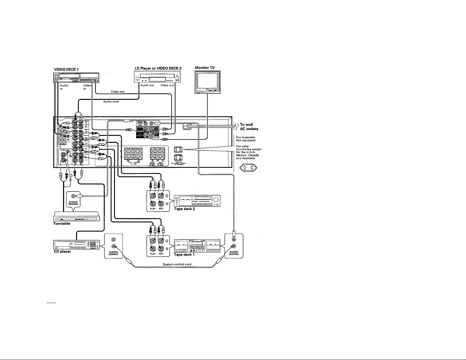
: Make connection as shown below. When connecting the related system components, refer also to the instruction manuals o
the related components.
Do not plug in the power lead until all connections are completed.
Automatic operation
When this unit is connected to KENWOOD system components such as a cassette deck and CD player through system control cords and the inpu
source is selected with the INPUT SELECTOR, the selected component starts to play automatically. Inversely, playing a component automatical!'
selects that source as the input to this unit. The automatic operation also occurs when the provided remote control is used.
I Notes I
“T7“Cdnnect all cords firmly. If connections are loose, there could be loss of sound or noise, produced,
2. When plugging and unplugging connection cords, be sure to first remove the power cord from the AC outlet. Plugging / unplugging
connection cords without removal of the power cord can cause malfunctions or damage to the unit.
3. Do not connect up a power source which is larger than that indicated on the socket at the rear of the unit.
4. Insert the systecn control plugs completely into the jacks.
5. If the system control cords or audio cords are not connected properly, the remote control or automatic operation between system
components will not work properly.
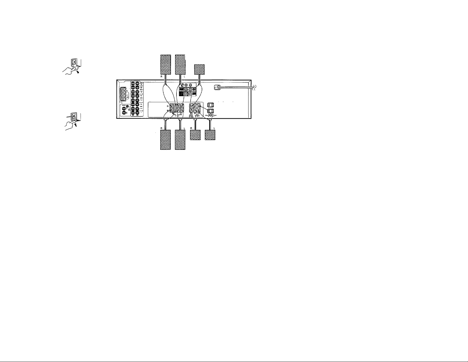
Connejoiion^
(D Push lever.
<D Insert cord.
(3) Return lever.
SPERKER SYSTEM A
Center speaker
(sa - len)
► Never short-circuit the + and - speaker cords.
I If the left and right speakers are connected inversely or if the
speaker cords are connected with reversed polarity, the sound
becomes unnatural with ambtgous acoustic image positioning.
Be sure to connect the speakers and speaker cords correctly.
► Proper sound will not be produced unless two rear speakers are
connected.
Rear speaker
(8Q ~ 16ii)
SPERKER SYSTEM B
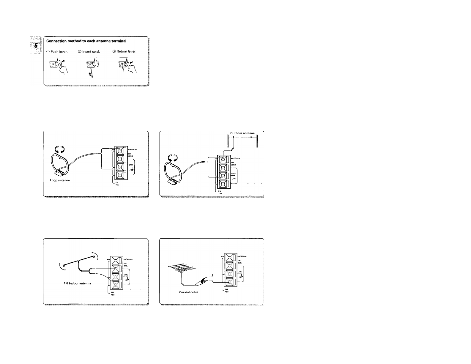
AM loop antenna connection
The supplied antenna is for indoor use. Place it as far as possible
from the main system, TV set, speaker cords and power cord, and
set it to a direction which provides the best reception.
AM outdoor antenna connection
If the reception is poor when the AM loop antenna is used, dis-.
tribute a vinyl-coated wire of more than 6 meters outdoors, with
out disconnecting the loop antenna.
Connectìqnp
FM indoor antenna connection
The supplied antenna is for indoor use. For stable reception, re
move the indoor antenna after installing an outdoor antenna as
soon as possible.
FM outdoor antenna connection
Lead the 75£i coaxial cable connected to the FM outdoor antenna
into the room and connect it to the FM 75Q terminal.
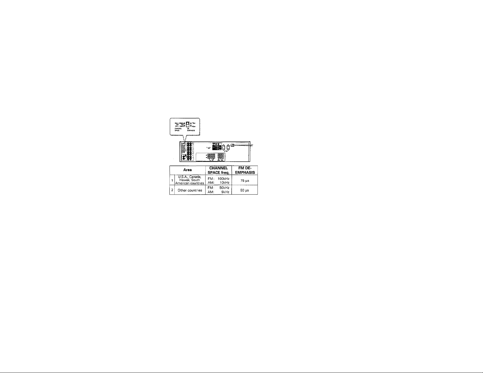
FM DE-EMPHAS/S/CHANNEL SPACE switch
(Except for U.SA, Canada, Mexico and Austraiia)
The FM DE-EMPHASIS / CHANNEL SPACE switch on the rear
panel is set to the correct setting that prevails in the area to which
the unit is shipped, However, if the FM DE-EMPHASIS / CHAN
NEL SPACE setting is not matched to the area where the unit is to
be used; for instance, when you moved from area 1 to area 2 or
vice versa, desired reception of AM / FM broadcasts is not ex
pected. In this case, change the FM DE-EMPHASIS / CHANNEL
SPACE setting in accordance with the area corresponding to the
table. The FM DE-EMPHASIS is switched over at the same time.
► When changing the setting of the FM DE-EMPHASIS / CHAN
NEL SPACE switch, first disconnect the power cord of the am
plifier, then reset the channel spacejswitch, connect the power
cord again, and turn the power on.
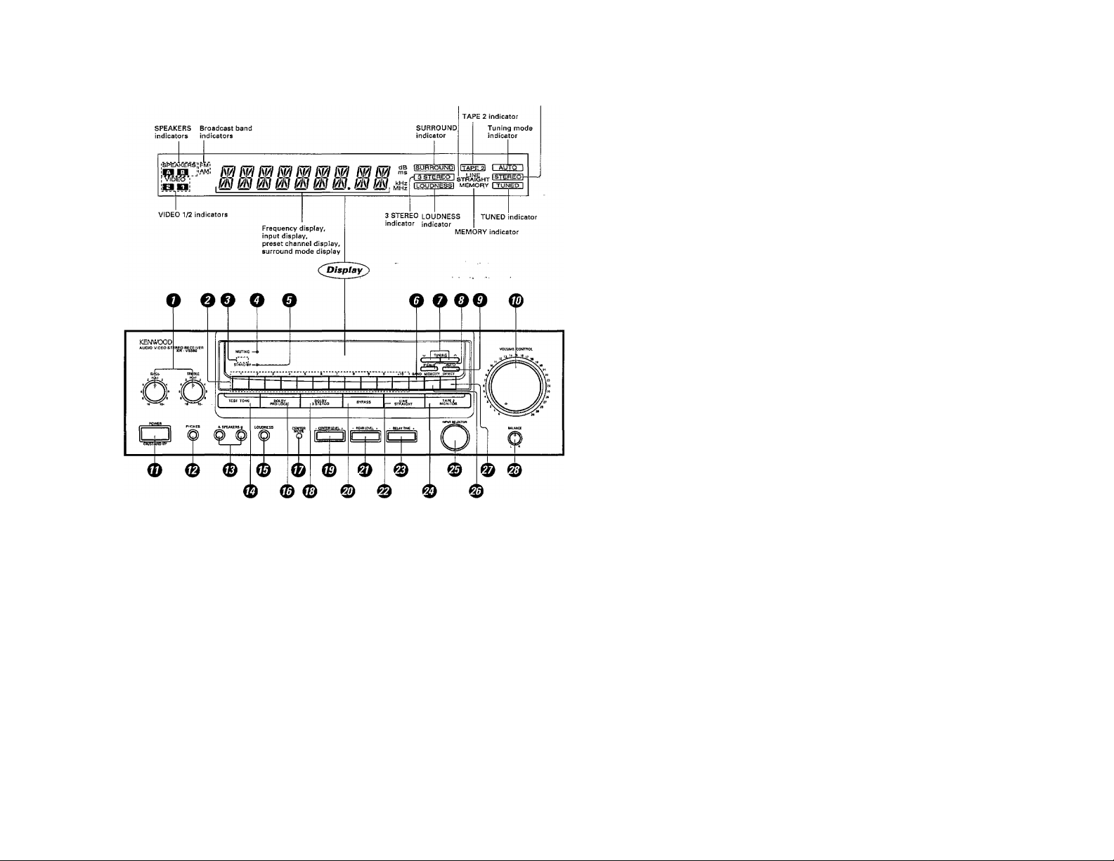
Tni-MiMìMIWltifilcai:
s
L!NE STRAIGHT
indicator Reception mode tndicator
OTOÑE control knobs
ONumeríc keys
ORemote control sensor
OMUTING indicator
0STAND BY indicator
©BAND key
Press to switch the broadcast band.
OTUNING keys
Press to tune broadcast stations.
©P.CALL key
Press to recall a preset station.
0AUTO key
Press to select the auto tuning mode.
©VOLUME CONTROL knob
©POWER key
©PHONES jack
Used for headphone listening.
©SPEAKERS A/B keys
Press to select the A and/or B speaker sys
tems.
©TEST TONE key
©LOUDNESS key
Press to enhance low frequencies.
©DOLBY PRO LOGIC key
©CENTER MODE key
Press to select the center mode of the
DOLBY PRO LOGIC surround play.
©DOLBY 3 STEREO key
©CENTER LEVEL key
©BYPASS key
Press to cancel the surround modes.
© REAR LEVEL key
©LINE STRAIGHT key
Press to reproduce the source with a highei
sound quality.
©DELAY TIME key
Press to adjust delay time.
©TAPE 2 {MONITOR) key
©INPUT SELECTOR knob
Turn to select the input sources.
©MEMORY key
Press to preset a station in the memory.
©DIRECT key
Press for direct station tuning based oi
numerical input.
© BALANCE control knob
Turn to adjust the volume balance between
left and right.
STANDYBYmode of POWER switch
When the power cord of this system is plugged into an AC outlet, the STAND BY indicator lights up regardless of. the ON/OFF setting ofthc
POWER switch. This indicates that a small amount of current is being supplied to the unit to back up the memory contents. This mode is referred;
to as the Stand By mode. While the STAND BY indicator is lit the power of the system can be switched ON/OFF from the remote control unit.
Loading...