


AUDIO VIDEO SURROUND RECEIVER
KR-V999D
INSTRUCTION MANUAL
KENWOOD CORPORATION
KR-V999D (En/T)
1
Preparations
Operations
About the supplied remote control . . .
Compared to standard remote controls, the remote control supplied with this receiver has several operation modes. These modes enable the remote control to perform on screen operations and control other audio/video components. In order to effectively use the remote control it is important to read the operating instructions and obtain a proper understanding of the remote control and how to switch its operation modes (etc.).
Using the remote control without completely understanding its design and how to switch the operation modes may result in incorrect operations.
Remote Control
Other
B60-3009-10 CH (T) WS

98/12 11 10 9 8 7 6 5 4 3 2 1 97/12 11 10 9 8 7 6 5 4 3
Getting started |
|
2 Before applying the power |
|
Units are designed for operation as follows. |
|
U.K. and Europe ....................................................................... |
AC 230 V only |
For the United Kingdom
Preparations |
Factory fitted moulded mains plug |
|
1.The mains plug contains a fuse. For replacement, use only a 13-Amp |
||
|
ASTA-approved (BS1362) fuse. |
|
|
2.The fuse cover must be refitted when replacing the fuse in the |
|
|
moulded plug. |
|
|
3.Do not cut off the mains plug from this equipment. If the plug fitted |
|
|
is not suitable for the power points in your home or the cable is too |
|
|
short to reach a power point, then obtain an appropriate safety |
|
|
approved extension lead or adapter, or consult your dealer. |
|
|
If nonetheless the mains plug is cut off, remove the fuse and dispose |
|
|
of the plug immediately, to avoid a possible shock hazard by |
|
|
inadvertent connection to the mains supply. |
|
|
|
IMPORTANT |
|
The wires in the mains lead are coloured in accordance with the |
|
|
following code: |
Blue : Neutral |
|
|
Brown : Live |
|
Do not connect those leads to the earth terminal of a three-pin |
|
|
plug. |
|
|
|
|
Caution : Read this page carefully to ensure safe operation.
KR-V999D (En/T)
REQUIREMENT BY NEDERLAND GAZETTE
Batteries are supplied with this product. When they empty, you should not throw away. Instead, hand them in as small chemical waste.
Operations
Safety precautions
WARNING : TO PREVENT FIRE OR ELECTRIC SHOCK, DO NOT EXPOSE THIS APPLIANCE TO RAIN OR MOISTURE.
|
|
|
CAUTION: TO REDUCE THE RISK OF ELECTRIC SHOCK, DO NOT REMOVE COVER (OR |
|
CAUTION |
|
|
|
|
|
BACK). NO USER-SERVICEABLE PARTS INSIDE, REFER SERVICING TO QUALIFIED SERVICE |
|
RISK OF ELECTRIC SHOCK |
|
|
|
DO NOT OPEN |
|
PERSONNEL. |
|
|
|
|
THE LIGHTNING FLASH WITH ARROWHEAD SYMBOL, WITHIN AN EQUILATERAL TRIANGLE, IS INTENDED TO ALERT THE USER TO THE PRESENCE OF UNINSULATED “DANGEROUS VOLTAGE” WITHIN THE PRODUCT’S ENCLOSURE THAT MAY BE OF SUFFICIENT MAGNITUDE TO CONSTITUTE A RISK OF ELECTRIC SHOCK TO PERSONS.
THE EXCLAMATION POINT WITHIN AN EQUILATERAL TRIANGLE IS INTENDED TO ALERT THE USER TO THE PRESENCE OF IMPORTANT OPERATING AND MAINTENANCE (SERVICING) INSTRUCTIONS IN THE LITERATURE ACCOMPANYING THE APPLIANCE.
Other
Unpacking
Unpack the unit carefully and make sure that all accessories are put aside so they will not be lost.
Examine the unit for any possibility of shipping damage. If your unit is damaged or fails to operate, notify your dealer immediately. If your unit was shipped to you directly, notify the shipping company without delay. Only the consignee (the person or company receiving the unit) can file a claim against the carrier for shipping damage.
We recommend that you retain the original carton and packing materials for use should you transport or ship the unit in the future.
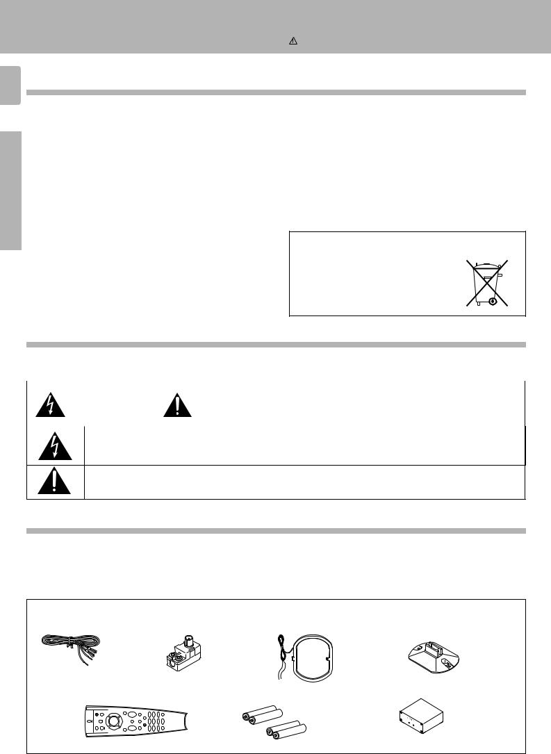
Accessories
FM indoor antenna (1) |
Antenna adaptor (1) |
AM loop antenna (1) |
Loop antenna stand (1) |
Remote control unit (1) |
Batteries (R03/AAA) (4) |
RF DEMODULATOR (1) |
|
|
|
LASER |
DISC RF |
|
|
|
|
|
|
|
POWERDEMODULATOR DEM- |
|
|
|
LOCK 999D |
AC adaptor (1) Power cord (1) RCA pin cord (2)
|
KR-V999D (En/T) |
Contents |
Caution : Read the pages marked carefully to ensure safe operation. |
|
|
|
Getting started |
2 |
|
Before applying the power ........................................................................................... |
2 |
|
Safety precautions ........................................................................................................ |
2 |
|
Unpacking ...................................................................................................................... |
2 |
|
Special features |
4 |
|
How to use this manual ................................................................................................ |
5 |
|
Names and functions of parts |
6 |
|
Setting up the system |
8 |
Preparations |
Connecting the antennas .............................................................................................. |
8 |
|
Connecting audio components ..................................................................................... |
9 |
|
Connecting video components ................................................................................... |
10 |
|
Digital connections ...................................................................................................... |
11 |
|
Connecting the system control ................................................................................... |
12 |
|
Connecting the speakers ............................................................................................ |
13 |
|
Making connections to another room (ROOM B) ...................................................... |
15 |
|
Preparing the remote control ...................................................................................... |
16 |
|
Preparing for surround sound |
17 |
|
Using the on-screen display ........................................................................................ |
17 |
|
Surround setup ............................................................................................................ |
18 |
3
Preparations
|
Normal playback |
20 |
|
Listening to a source component ............................................................................... |
20 |
|
Adjusting the sound .................................................................................................... |
21 |
|
Recording |
23 |
|
Recording audio .......................................................................................................... |
23 |
|
Recording video .......................................................................................................... |
24 |
|
Listening to radio broadcasts |
25 |
|
Tuning (non-RDS) radio stations ................................................................................. |
25 |
|
Tuning radio stations by frequency (DIRECT tuning) ................................................. |
26 |
|
Using RDS (Radio Data System) ................................................................................. |
27 |
|
Using the DISPLAY key .............................................................................................. |
27 |
Operations |
|
|
|
Presetting RDS stations (RDS AUTO MEMORY) ....................................................... |
28 |
|
Receiving preset RDS stations ................................................................................... |
28 |
|
Presetting radio stations manually .............................................................................. |
29 |
|
Receiving preset stations ........................................................................................... |
29 |
|
Receiving preset stations in order (P.CALL) ............................................................... |
29 |
|
Tuning by program type (PTY search) ......................................................................... |
30 |
|
Reserving the desired information ............................................................................. |
32 |
|
Ambience effects |
34 |
|
Sound modes .............................................................................................................. |
34 |
|
Surround play .............................................................................................................. |
36 |
|
Getting the most from your remote control |
40 |
|
Registering setup codes for other components ......................................................... |
40 |
|
Operating other components ...................................................................................... |
42 |
|
Changing (confirming) the operation mode ................................................................ |
43 |
Remote Control |
Preparing for automatic operations (MACRO play) .................................................... |
44 |
|
Executing an automatic operation .............................................................................. |
46 |
|
Controlling the sound in another room (ROOM B) ..................................................... |
47 |
|
Setup code correlation ................................................................................................ |
48 |
|
FutureSet upgrade option ........................................................................................... |
49 |
Operations
Remote Control
Set up code chart In case of difficulty
Other  Specifications
Remote operation of other components
51
57
59
60
Other
Special features
|
|
KR-V999D (En/T) |
4 |
True home theater sound |
|
|
This receiver incorporates a wide variety of surround modes to bring you maximum enjoyment from your video software. Select |
|
|
a surround mode according to your equipment or the software you are going to play and enjoy! |
› |
Preparations
Dolby Digital (AC-3)
The DOLBY DIGITAL (AC-3) mode lets you enjoy full digital surround from software processed in the Dolby Digital (AC-3) format. Dolby Digital (AC-3) provides up to 5.1 channels of independent digital audio for better sound quality and more powerful presence than conventional Dolby Surround.
Dolby Pro Logic & Dolby 3 Stereo
This surround system reproduces theater-like surround sound from video software marked 
 .
.
The PRO LOGIC mode uses the built-in directivity enhancer circuit to control the Left, Center, Right and Surround channel audio signals and reproduce a real sense of sound motion .
The 3 STEREO mode uses the directivity enhancer circuit to provide proper acoustic positioning and a real sense of sound motion even when only the front and center speakers are used.
Operations
New DSP surround modes
The DSP (Digital Signal Processor) used for this receiver incorporates a variety of high quality adjustable sound fields, like "ARENA", "JAZZ CLUB", "STADIUM", "CHURCH" and "THEATER", to add the “presence” associated with an arena, jazz club or stadium (etc.) to the original signal. It is compatible with almost any kind of program source.
Universal IR (InfraRed) remote control
In addition to the basic receiver and OSD operations, the remote control supplied with this receiver can also operate almost all of your remote controllable audio and video components. Just follow the simple setup procedure to register the components you have connected. ‚
Other
Dual IR emitters
This remote control has two IR emitters: one to send commands in a straight line over long distances, allowing you to control the receiver and your other components from farther away; and one for wide dispersion of commands in a closer proximity, for near-field operation even when the remote control is not pointed directly at the respective component. ^
MACRO play
The MACRO function lets you perform a series of operations automatically, like turning ON the power of the receiver and connected components, switching the input selectors, and starting playback. (Be sure to register your components before starting the macro set up procedure.) r
FutureSet, automatic update feature
This function lets you update the remote control so it can operate new components which do not appear in the setup code list at the end of the manual. Therefore, the remote control will always be compatible. o
Easy surround setup and operation with OSD (On Screen Display)
This function takes advantage of your monitor TV to simplify the surround setup procedures so you can quickly and easily
match the surround processing to your speaker system, and your listening environment. |
|
You can also use OSD during playback to customize the DSP surround modes, etc. |
& |
|
Special features |
|
|
|
KR-V999D (En/T) |
RDS (Radio Data System) tuner |
5 |
The receiver is equipped with a RDS tuner that provides several convenient tuning functions: RDS Auto Memory, to automatically preset up to 40 RDS stations broadcasting different programs; station name display, to show you the name of the current broadcast station; and PTY search to let you tune stations by program type. ¶
On screen Radio Text
Although most RDS compatible tuners and receiver's can display the name of the current broadcast station, this receiver goes one step further by allowing you to display the station name, as well as any other text messages broadcast from the current station, in large easy to read characters on the screen of your monitor TV. You can even display radio text from an RDS station while enjoying a different source component! ¶°
PTY (Program TYpe) search
Lets you tune stations by specifying the type of program you want to hear. º
EON (Enhanced Other Networks) reservation
The EON function lets you monitor information on other stations so you can receive traffic, news, or information programs as soon as they are broadcast, even they are broadcast on a station different from the one you are currently listening to. When the broadcast ends, the receiver returns to the original station. When listening to KENWOOD source components connected with system control cords, the input selector on the receiver automatically switches to the tuner when a program you desire is broadcast. ¤
Dual room installation capability
In addition to the standard "A" speaker output terminals for use in your main system, this receiver also incorporates separate "B" speaker terminals and "Room B" RCA video and stereo output jacks. This system lets you use the remote control to control and output audio and video to "Room B" independent of "Room A." %u
New TRAITR transistor adopted in the final stage
A new TRAITR transistor which features superior temperature tracking characteristics has been adopted in the final stage of the power amplifier block. This new TRAITR transistor combines a temperature compensation resistor with an emitter resistor and final transistor to provide ideal temperature compensation characteristics and minimize distortion caused by temperature variations.
How to use this manual
This manual is divided in to four sections, Preparations, Operations, Remote Control, and Other.
Preparations
Shows you how to connect your audio and video components to the receiver and prepare the surround processor.
We've tried to make setting up your system as easy as possible. However, since this receiver works with all of your audio and video components, connecting the system can be fairly complex.
Operations
Shows you how to operate the various functions available from the receiver.
Remote Control
Shows you how to operate the various functions available from the remote control.
We've designed this remote control to integrate your entire audio/video system and let you operate all of your entertainment components
— your TV, VCR, LD player, CD player, etc. Remember that before you can use the remote control to operate these components, they must be registered with a proper setup code.
Other
Includes additional information such as; a list of setup codes for registering your other components, a troubleshooting guide, specifications, and a reference guide to the remote operations available for registered components.
Preparations
Operations
Remote Control
Other
Names and functions of parts
KR-V999D (En/T)
6 |
|
|
|
|
|
Frequency display, |
SURROUND |
|
|
|
|
|
|
||||
|
|
|
|
|
|
Input display, |
indicator AC-3 |
|
|
|
|
|
|
||||
|
|
|
|
|
|
Preset channel display, |
|
DSP indicator |
|
||||||||
|
RDS indicators |
Surround mode display |
Band indicators |
indicator |
|
||||||||||||
|
|
|
|
|
|
||||||||||||
|
|
|
|
|
|
|
|
|
|
|
|
|
|
|
|
|
MEMORY indicator |
|
|
|
|
|
|
|
|
|
|
|
|
|
|
|
|
|
|
|
|
|
|
|
|
|
|
|
|
|
|
|
MEMORY |
|
|
||
|
TA |
NEWS INFO. |
|
|
|
FM |
AC-3 |
|
TAPE 2 |
|
STEREO indicator |
||||||
|
ROOM A |
B |
*******;**MHz |
S. DIRECT |
|
TUNED |
|
||||||||||
|
RDS |
EON |
PTY |
|
|
|
AM |
SURROUND |
|
DSP |
AUTO |
|
|
AUTO indicator |
|||
|
TP |
SP. A B |
|
|
|
kHz |
3 STEREO |
LOUDNESS |
STEREO |
|
|
|
|||||
|
|
|
|
|
|
|
|||||||||||
|
|
|
|
|
|
|
|
|
|
|
|
|
|
|
|
|
|
TUNED indicator
Preparations |
|
|
|
Speaker indicators |
|
|
|
|
|
3 STEREO indicator |
|
LOUDNESS indicator |
|
||||||
ROOM indicators |
|
|
|
|
|
|
|
|
|
S.DIRECT indicator |
|
||||||||
|
|
|
|
|
|
|
|
|
|
|
|
||||||||
|
|
|
|
|
|
|
|
|
|
|
|
|
|
TAPE 2 |
|
|
|||
|
|
|
|
|
|
|
|
|
|
|
|
|
|
indicator |
|
|
|||
|
|
|
|
|
|
|
|
|
Display |
|
|
|
|
|
|
|
|||
|
1 2 |
3 4 5 6 7 |
|
|
|
|
8 9 0 !@ # |
|
$ |
||||||||||
|
AUDIO−VIDEO SURROUND RECEIVER KR-V999D |
|
|
|
|
|
|
|
|
|
|
|
|
|
|||||
|
|
|
|
|
|
|
|
|
|
|
|
|
|
|
DOLBY |
|
|
|
|
|
|
|
|
|
|
|
|
|
|
|
|
|
|
|
DIGITAL |
PRO LOGIC |
|
|
|
|
|
|
|
|
|
|
|
|
|
|
|
|
|
|
3 STEREO |
STEREO |
|
|
|
|
|
|
|
|
|
2 CH |
|
LEVEL |
|
|
|
|
|
|
SOURCE DIRECT |
DSP |
INPUT SELECTOR |
VOLUME CONTROL |
|
|
BASS |
|
|
TREBLE |
STANDBY DOWNMIX INDICATOR |
|
|
|
|
|
|
|
|
|
|||||
|
|
|
|
|
|
|
|
|
|
|
|
|
|
|
|
|
|
||
|
FLAT |
|
|
FLAT |
|
|
|
|
|
|
|
|
|
|
+10/ |
|
|
|
|
|
|
|
|
|
1 |
2 |
3 |
4 |
5 |
6 |
7 |
8 |
9 |
0 |
|
|
|
|
|
|
|
|
|
|
PTY SEARCH |
LOUDNESS |
|
|
|
||||||||||
|
|
|
|
|
|
|
|
|
|
|
|
|
|
|
DIMMER |
|
|
|
|
|
ON/STANDBY |
|
|
|
|
|
|
|
|
|
|
|
|
TUNING |
|
|
|
|
|
|
−10 |
+10 |
−10 |
+10 |
DIRECT |
MEMORY |
|
AUTO |
|
BAND |
|
|
|
MUTE TAPE 2 MONITOR |
|
|
|
||
|
POWER |
|
|
|
|
|
|
|
|
|
|
|
|
||||||
|
|
|
|
|
|
|
|
|
|
|
|
|
|
|
|
DOWN |
UP |
||
|
|
|
|
|
|
|
|
|
|
|
|
|
|
|
|
|
|||
|
-ON –OFF |
|
|
|
|
|
|
|
|
|
|
|
|
|
|
|
|
|
|
|
PHONES |
|
|
|
|
|
|
|
|
|
|
|
|
|
|
|
AV AUX |
|
|
|
|
|
|
|
|
|
|
|
|
|
|
|
|
|
|
|
|
|
|
Operations |
T R A I T R |
|
|
A |
SPEAKERS |
|
B |
TA/NEWS/INFO |
PTY |
|
DISPLAY |
|
|
|
|
|
|
||
|
|
|
|
|
|
|
|
|
|
|
|
|
|
|
|
|
|||
thermally reactive advanced instantaneous transistor |
|
|
|
|
|
|
|
|
|
|
Full Digital Decoding |
|
|
||||||
|
|
|
|
|
|
|
|
|
|
|
|
|
|
|
|
||||
|
|
|
|
|
|
|
|
|
|
|
|
|
|
|
|
S−VIDEO VIDEO L - AUDIO - R |
|
||
% |
|
^& * ( ) ¡ ™ £¢ §¶ • |
|
|
|||||||||||||||
|
|
|
|
||||||||||||||||
Other
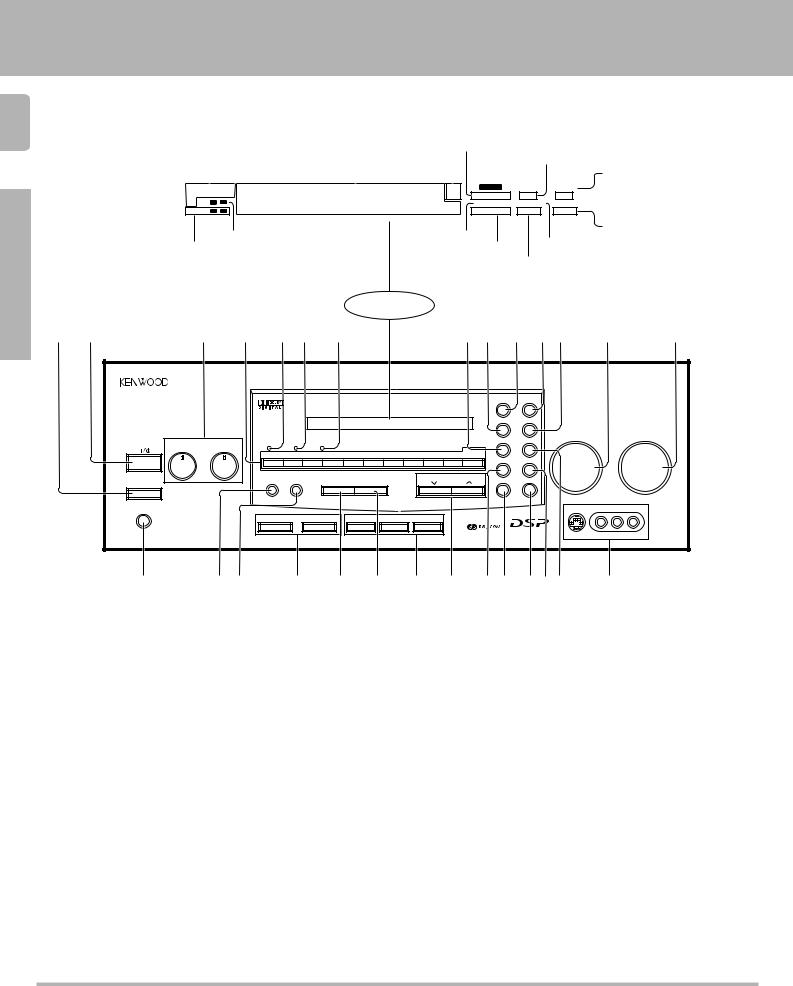
1 POWER key |
) |
Use to turn the main power ON/OFF.
2ON/STANDBY ( 
 ) key )
Use to switch the power ON/STANDBY when the POWER is turned ON.
3 Tone Control knobs |
¡ |
4 Numeric keys |
|
5 STANDBY indicator |
|
62 CH DOWNMIX indicator
Lights when an DOLBY DIGITAL (AC-3) format signal is being downmixed to 2 channel stereo.
7 LEVEL indicator |
( |
Lights when the level of the signal being input is too high.
8 SOURCE DIRECT key |
™ |
9 DOLBY 3 STEREO key |
› |
Use to turn on the DOLBY 3 STEREO mode.
0 DOLBY DIGITAL key |
› |
Use to turn on the DOLBY DIGITAL (AC-3) mode.
! PRO LOGIC key |
› |
Use to turn on the DOLBY PRO LOGIC mode.
@STEREO key
Use to cancel the surround mode.
# INPUT SELECTOR knob |
) |
Use to select the input sources. |
|
$ VOLUME CONTROL knob |
) |
% PHONES jack |
™ |
Use for headphone listening. |
|
^ DIRECT key |
§ |
Use to tune radio stations directly by numerical input.
& MEMORY key •ª
Use to store radio stations in the preset memory.
* SPEAKERS A/B keys )u
Use to turn the speakers ON/OFF.
( AUTO key |
∞ |
Use to select the auto tuning mode. |
|
) BAND key |
∞ |
Use to select the broadcast band. |
|
¡ RDS keys |
¶º¤ |
™ TUNING keys |
∞ |
Use to tune in radio broadcasts.
£DIMMER key
Use to adjust the brightness of the display.
¢ MUTE key |
¡ |
Use to mute the sound. |
|
∞ TAPE 2 MONITOR key |
£ |
Use to monitor a recording. |
|
§ LOUDNESS key |
¡ |
Use to activate the frequency weighting network.
¶ DSP key |
fi |
Use to turn on, or switch, the DSP mode.
• AV AUX jacks |
0 |
About the STANDBY indicator
This unit has a STANDBY indicator. When the STANDBY indicator is lit, the unit consumes a small amount of power to preserve the memory. This is called STANDBY mode. This mode also lets you turn the power ON using the remote control.
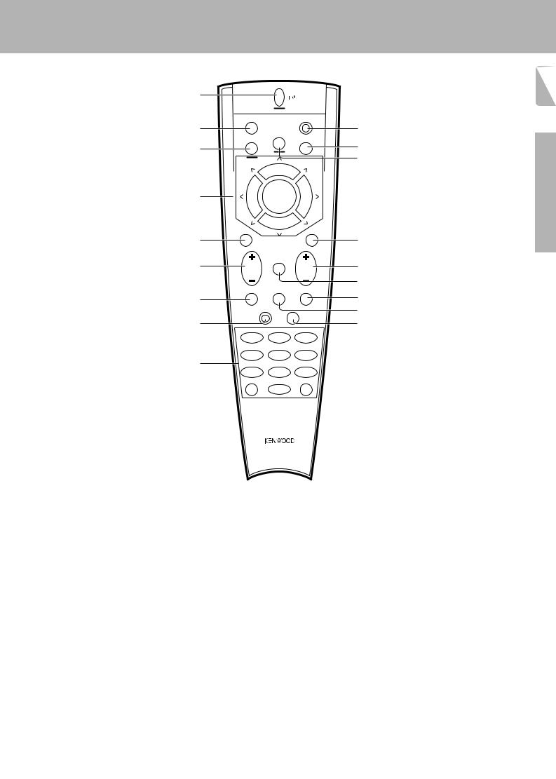
1 POWER key |
w |
Use to turn the receiver on and off.
Use in combination with the input selector (AUDIO, VIDEO, or TV) keys and SHIFT key to turn various components on and off.
2 MACRO key |
r |
Use in combination with the AUDIO, VIDEO, or TV keys to execute a series of commands automatically (MACRO PLAY).
3 VIDEO selector key |
‚ |
Selects the video inputs (VIDEO 1, VIDEO 2, VIDEO 3, VIDEO 4, AV AUX) and sets the remote to operate the component registered at the respective input.
4 Multi control keys |
P |
Use to operate the selected component and to operate the on-screen display.
5 REC key |
P |
Use to operate the selected component. |
|
6 TUNING/SKIP key |
*P |
Use during the setup procedure to specify various settings. Use to operate the tuner or selected component.
Names and functions of parts
KR-V999D (En/T)
1 |
POWER |
|
|
|
|
MACRO |
|
SHIFT |
|
2 |
|
AUDIO |
|
0 |
|
|
|
|
|
|
VIDEO |
|
TV |
! |
3 |
|
|
|
|
|
|
|
|
@ |
|
P. CALL |
8 |
P. CALL |
|
|
|
BAND |
|
|
4 |
4 |
6 |
¢ |
|
|
|
7 |
|
|
|
REC |
|
GUIDE |
|
5 |
|
|
|
# |
|
TUNING/SKIP |
|
VOLUME |
|
6 |
|
MUTE |
|
$ |
|
|
|
||
|
|
LISTEN |
|
% |
|
SUBWOOFER |
SOUND |
|
|
|
MODE |
^ |
||
7 |
|
|
|
|
|
FUNCTION |
|
|
& |
|
|
SETUP |
|
|
8 |
SHIFT |
|
* |
|
|
|
|||
|
MENU |
THEME |
FAV |
|
|
1 |
2 |
3 |
|
|
TV/SAT/VID |
INFO |
ALT AUD |
|
9 |
4 |
5 |
6 |
|
+100 |
REPEAT |
RANDOM |
|
|
|
7 |
8 |
9 |
|
|
ROOM A |
DISPLAY |
ROOM B |
|
|
+10 |
0 |
ENT |
|
REMOTE CONTROL UNIT
RC-R0905
7 SUBWOOFER key |
° |
Use in combination with the VOLUME +/– keys to adjust the volume of the subwoofer.
8 FUNCTION SHIFT key |
P |
Use in combination with the numeric keys to execute alternate commands.
9 Numeric keys |
P |
Provide functions identical to those of the original remote supplied with the component you are controlling.
To access the functions printed above the keys, Press within 3 seconds of pressing the FUNCTION SHIFT key. Function availability varies for each component.
0 SHIFT key |
e |
Use in combination with the AUDIO and VIDEO keys to change the remote control mode without changing the input selector or in combination with the POWER key to turn on and off components programmed into the remote.
! TV selector key |
‚ |
Sets the remote to operate a TV or cable box (TV 1, TV 2, CABLE). This key does not change the input selector on the receiver.
@ AUDIO selector key |
‚ |
Selects the audio inputs (CD, TAPE1/MD. TUNER, PHONO) and sets the remote to operate the respective KENWOOD audio component.
If you connect audio components from KENWOOD and other makers to the TAPE1/MD or CD jacks, you can set the remote to operate these components by registering the appropriate setup code at the respective input.
# GUIDE key |
P |
Use to activate the OSD menu functions of registered components.
$ VOLUME key |
) |
Use to adjust the receiver volume. |
|
% MUTE key |
¡ |
Use to temporarily mute the sound. |
|
^ SOUND key |
fl |
Use to activate the Sound OSD and set the remote to OSD control mode.
& LISTEN MODE key |
° |
Use to select the desired surround mode. |
|
* SETUP key |
* |
Use to activate the Setup OSD and set the remote to OSD control mode.
7
Preparations
Operations
Remote Control
Other

Setting up the system
KR-V999D (En/T)
8 Connecting the antennas
Preparations
Operations
Make connections as shown below.
Do not connect the power cord to a wall outlet until all connections are completed.
Antenna terminal connections
1 Push lever. |
2 Insert cord. |
3 Return lever. |
|
|
||
|
|
|
|
|
|
|
|
|
|
|
|
|
|
|
|
|
|
|
|
|
|
|
|
|
|
|
|
|
|
|
|
|
|
|
AM loop antenna |
FM indoor antenna |
The supplied loop antenna is for use indoors. Place it as far as |
The supplied indoor antenna is for temporary use only. For stable |
possible from the receiver, TV set, speaker cords and power |
signal reception we recommend using an outdoor antenna. |
cord, and adjust the direction for best reception. |
Disconnect the indoor antenna when you connect one outdoors. |
AM loop antenna
FM indoor antenna
FM outdoor antenna
Lead the 75Ω coaxial cable connected to the FM outdoor antenna into the room and connect it to the FM 75Ω terminal.
AM |
GND
FM75Ω
ANTENNA
1 |
Loosen screw. |
FM outdoor antenna |
2 |
Insert antenna cable |
|
3 |
Tighten screw. |
|
4 |
Plug securely into 75 Ω terminal. |
|
5 |
Find the position that provides best reception. |
|
6 |
Fix both ends. |
|
Other
75 Ω coaxial cable connection
1Arrange the coaxial cable as illustrated.
5 4 3 (mm)
RG-6(5C-2V) or RG-59(3C-2V)
2Open the antenna adaptor.
Open the claws with the fingers to
release the lock and pull out the cover. 
Claw
3Remove the inner conductor from the groove of pole A and insert it in the groove of pole B.
Pole A
Pole B
4 Insert into the slit on |
|
5 Close the cover and con- |
|
|
|
Ω |
the clip. Fasten the |
|
nect the adaptor to the |
|
|
75 |
|
bands A and B,using |
Band A |
antenna terminal. |
75 |
Ω |
|
|
|
|
300 |
|
|
||
a pair of pliers. |
|
|
|
Ω |
|
|
|
|
|
|
|
|
|
Band B
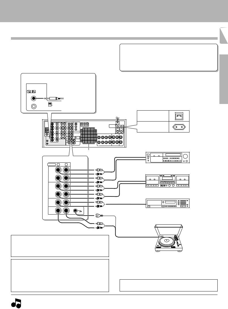
Connecting audio components
Setting up the system
KR-V999D (En/T)
9
Make connections as shown below. |
|
Microcomputer malfunction |
|
||
When connecting the related system components, be sure |
|
||||
to also refer to the instruction manuals supplied with the |
If operation is not possible or an erroneous display appears, even |
||||
components you are connecting. |
|
||||
|
though all connections have been made properly, reset the |
||||
Do not connect the power cord to a wall outlet until all |
|||||
microcomputer referring to “In case of difficulty”. |
U |
||||
connections are completed. |
|
||||
|
|
|
|||
|
SYSTEM CONTROL jacks |
|
|
||
|
For SYSTEM CONTROL con- |
|
|
||
SYSTEM |
nections to KENWOOD com- |
|
|
||
CONTROL |
ponents |
@ |
|
|
|
ƒ |
|
|
|||
SYSTEM CONTROL |
|
|
|||
|
|
|
|||
|
cord |
|
|
|
|
|
SL 16 |
|
|
|
|
|
XS 8 SYSTEM CONTROL switch |
Shape of AC outlets |
|
||
|
|
|
|
||
|
|
To AC wall outlet |
|
||
|
|
|
U.K. |
|
|
|
|
|
Except for U.K. |
|
|
Preparations
Ventilation fan
AUDIO R |
L |
REC
OUT
TAPE 2
MONITOR
PLAY
IN
REC
OUT
TAPE 1/MD
PLAY
IN
CD
PHONO
Ventilation fan
The ventilation fan runs during high-power reproduction. To allow for proper ventilation, maintain a certain distance between the wall and the rear of the component.
Caution regarding placement
To maintain proper ventilation, be sure to leave a space around the unit (from the largest outer dimensions, including projections) equal to, or greater than shown below:
Left and right panels: 10 cm, Rear panel: 10 cm, Top panel: 50 cm
REC |
Operations |
|
PLAY
Cassette deck 2* or graphic equalizer
REC
PLAY
Cassette deck 1 or
MD recorder
CD player
Other
Record player
*Do not connect a System Control cord to a cassette deck connected to the TAPE 2 MONITOR jacks.
1. Connect all cords firmly. Loose connections may prevent proper sound transmission or produce noise.
 2. Be sure to remove the power cord from the AC outlet before plugging or unplugging any connection cords. Plugging / unplugging connection Notes cords without disconnecting the power cord can cause malfunctions and may damage the unit.
3.Do not connect power cords from components whose power consumption is larger than what is indicated on the AC outlet at the rear of this unit.
Setting up the system
KR-V999D (En/T)
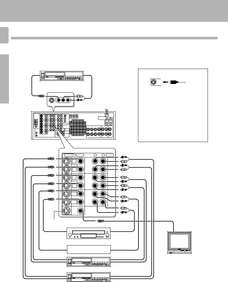
1 0 Connecting video components
Preparations
Operations
Other
Make connections as shown below.
When connecting the related system components, be sure to also refer to the instruction manuals supplied with the components you are connecting.
Do not connect the power cord to a wall outlet until all connections are completed.
Video deck or video camera
VIDEO |
|
AUDIO |
OUT |
|
OUT |
|
(Front Panel) |
|
|
AV AUX |
|
|
S-VIDEO VIDEO L−AUDIO−R |
To AC wall outlet |
|
|
About the S-VIDEO jacks
MONITOR
OUT
S-VIDEO cord
Use the S-VIDEO jacks to make connections to video components with S-VIDEO IN/OUT jacks.
•If you use the S-VIDEO jacks to connect your video playback components, be sure to use the S-VIDEO jacks when connecting your monitor and video recording components.
•When both S-VIDEO and normal video plugs are connected to the MONITOR OUT jacks, the receiver's on screen display is output from the S-VIDEO jack only.
S-VIDEO VIDEO |
R |
L AUDIO |
REC |
REC |
|
OUT |
OUT |
|
VIDEO 1 |
VIDEO 1 |
|
PLAY |
PLAY |
|
IN |
IN |
|
REC |
REC |
|
OUT |
OUT |
|
VIDEO 2 |
VIDEO 2 |
|
PLAY |
PLAY |
|
IN |
IN |
|
VIDEO 3 |
VIDEO 3 |
|
PLAY IN |
PLAY IN |
|
VIDEO 4 |
VIDEO 4 |
|
PLAY IN |
PLAY IN |
|
MONITOR |
|
|
OUT |
|
|
S-VIDEO jacks
|
|
Yellow RCA |
OUT |
OUT |
pin cord |
VIDEO IN |
|
|
LD player |
|
|
|
OUT |
TV/CABLE tuner |
OUT |
|
|
|
|
|
|
|
OUT |
|
OUT |
Monitor TV |
|
IN |
Video deck 2 |
IN |
|
|
|
|
|
|
|
OUT |
|
OUT |
|
Video inputs and outputs |
IN |
Video deck 1 |
IN |
Audio inputs and outputs |
(Yellow RCA pin cords) |
|
|
(Red and white RCA pin cords) |
|
|
|
|
Digital connections
Setting up the system
KR-V999D (En/T)
1 1
Make connections as shown below.
The digital in jacks can accept either Dolby Digital (AC-3) or PCM signals (the input signal type is detected automatically). When connecting the related system components, be sure to also refer to the instruction manuals supplied with the components you are connecting.
Do not connect the power cord to a wall outlet until all connections are completed.
Connect components capable of outputting Dolby Digital (AC-3) or standard PCM format digital signals.
VIDEO2
(OPTICAL)
VIDEO3
VIDEO4 |
RCA pin cord |
OPTICAL DIGITAL OUT (AUDIO)
Optical fiber cable
COAXIAL DIGITAL OUT (AUDIO)
RCA pin cord
Component with an AC-3 (or PCM) OPTICAL DIGITAL OUT
Connect the video signal and analog audio signals to the VIDEO 2 jacks. (See "Connecting video components".)
Component with an AC-3 (or PCM) COAXIAL DIGITAL OUT
Connect the video signal and analog audio signals to the VIDEO 3 jacks. (See "Connecting video components".)
AC-3 |
AC-3 DIGITAL |
AC-3 RF |
DC IN |
OUTPUT |
INPUT |
12V |
|
DIGITAL IN |
|
|
|
OFF ON
@ #
AC-3 RF OUT (AUDIO)
RCA pin cord
LASER DISC RF DEMODULATOR DEM-999D
POWER LOCK
To connect an LD player with a DIGITAL RF OUT. Connect the LD player to the KENWOOD RF digital demodulator (DEM-999D). Then connect the demodulator to the VIDEO 4 DIGITAL IN.
Connect the video signal and analog audio signals to the VIDEO 4 jacks. (See "Connecting video components".)
Preparations
Operations
AC-3 RF Demodulator DEM-999D
12
LASER DISC RF DEMODULATOR DEM-999D
POWER LOCK
1POWER indicator
Lights (red) when the power switch (5) is set to ON .
2LOCK indicator
Lights when an AC-3 RF signal is input to the AC-3 RF INPUT jack (4).
3AC-3 DIGITAL OUTPUT (coaxial)
Connect this jack to the coaxial AC-3 DIGITAL IN jack on your receiver. It outputs AC-3 coaxial digital signals when the POWER (5) is set to ON and an AC-3 RF signal is input to the AC-3 RF INPUT jack (4).
3 |
4 5 6 |
Other |
||
|
||||
|
AC-3 DIGITAL |
AC-3 RF |
DC IN |
|
|
OUTPUT |
INPUT |
12V |
|
OFF ON
@ #
EXTERNAL DC SUPPLY DC 12V
4AC-3 RF INPUT
Connect this jack to the AC-3 RF OUTPUT jack on your LD player.
5POWER switch
Use to switch the power ON/OFF.
6DC IN (12V) jack
Connect this jack and inlet power cord to the AC adaptor supplied with your demodulator. Connect the power cord to a wall outlet after completing all of the other connections.
Place the power supply away from the demodulator, receiver, and any antennas.
Setting up the system
KR-V999D (En/T)
1 2 Connecting the system control
Preparations
Operations
Connecting system control cords after connecting a KENWOOD audio component system lets you take advantage of convenient system control operations.
There are two KENWOOD system control modes. Make connections according to the groups of terminal symbols shown below.
ƒMode : lets you combine f, ƒ, and F terminals 
 Mode : for
 terminals only
This unit is compatible with both [XS8] and [SL16] modes. It comes from the factory set to the [SL16] mode. To switch to the [XS8] mode, follow the instructions in “SWITCHING FROM [SL16] TO [XS8]” below.
EXAMPLE: [XS8] mode connections
The underlined portion represents the setting of the system control mode.
[SL16] [XS8] |
Receiver |
|
|
|
|
|
|
[SL16] |
MD recorder |
|
|
|
|
|
SYSTEM |
|
|
|
|
[SL16] [XS] [XS8] [XR] |
Cassette deck |
|
|
|
|||
|
CONTROL |
||
|
|||
[SL16] [XS] [XS8] |
|
|
cord |
CD player |
|
|
|
|
|
||
|
|
|
|
|
|
|
|
EXAMPLE: [SL16] mode connections
The underlined portion represents the setting of the system control mode.
[SL16] [XS8] |
Receiver |
|
|
|
|
|
|
|
|
|
|
[SL16] |
MD recorder |
|
SYSTEM |
|
|||
[SL16] [XS] [XS8] [XR] |
|
|
|
|
|
||
Cassette deck |
|
||
|
|||
|
CONTROL |
||
|
|||
[SL16] [XS] [XS8] |
|
|
cord |
CD player |
|
|
|
|
|
||
|
|
|
|
[XS] |
Record player |
[XS] |
Record player |
•In order to take advantage of the system control operations, the components must be connected to the correct jacks. To use a CD player it must be connected to the CD jacks. To use a cassette deck (or MD recorder) it must be connected to the TAPE1/MD jacks. When using more than one CD player (etc.) only the one connected to the specified jacks may be connected for system control.
•Some CD players and cassette decks are not compatible with the [SL16] system control mode. Be sure to use the [XS8] system control mode when making system connections with equipment that is not [SL16] compatible.
•Some MD players are not system control compatible. You cannot make system control connections to this kind of equipment.
1.[SL16] equipment cannot be combined with [XR], [XS], and [XS8] equipment for system operations. If your equipment consists of this kind of combination, please do not connect any system control cords. Even without
system control cords, normal operations can be carried out without effecting performance.
Notes 2. Do not connect system control cords to any components other than those specified by KENWOOD. It may cause a malfunction and damage your equipment.
3. Be sure the system control plugs are inserted all the way in to the system control terminals.
Other
SYSTEM CONTROL OPERATIONS
Remote Control
Lets you operate this unit with the system remote supplied with the receiver.
Automatic Operation (except [XR] equipment)
When you start playback from a source component, the input selector on this unit switches to that component automatically.
Synchronized Recording (except [XR] equipment)
Lets you synchronize recording with the start of playback when recording from CD, MD or analog discs.
SWITCHING FROM [SL16] TO [XS8]
You can easily change the system control mode by adjusting the position of the SYSTEM CONTROL switch on the rear panel.
Do this operation after completing all connections.
SL 16 |
For [SL16] |
XS 8 |
For [XS8] |
•This operation will not effect items stored in the memory.
•After switching the system control mode, turn the power off and then on once to confirm the new setting.
Registering setup codes for KENWOOD audio components
• Once you finish making the system connections, be sure to register the appropriate setup code for each component. |
‚ |
•If you own remote controllable KENWOOD audio components that are not compatible with system control (or cannot be combined with your other system control components), registering the setup code enables you to control those components using the remote control supplied with this
unit (without connecting system control cords). To register setup codes for your remote controllable KENWOOD audio components, see "Registering setup codes for other components". ‚
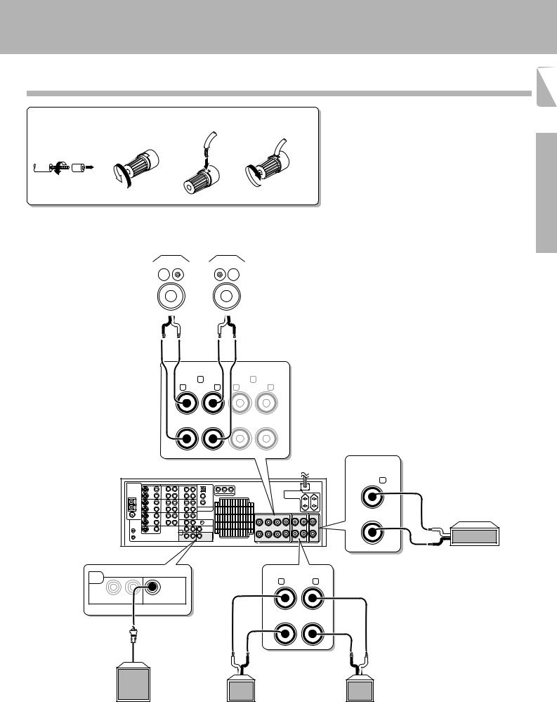
Connecting the speakers
1 Strip coating. |
2 Loosen. |
3 Insert. |
4 Secure. |
||
|
|
|
|
|
|
Front Speakers A
(4Ω~16Ω)
Right |
|
Left |
|
|
|
|
|
|
Setting up the system
KR-V999D (En/T)
1 3
•Never short circuit the + and – speaker cords.
•If the left and right speakers are connected inversely or the speaker cords are connected with reversed polarity, the sound will be unnatural with ambiguous acoustic imaging. Be sure to connect the speakers correctly.
Preparations
· ª ª ·
FRONT SPEAKERS (4−16 Ω)
A B
R L R L
+
−
CENTER
SPEAKER (4−16Ω) C
+
−
PRE |
SURROUND SPEAKERS |
OUT |
R (4−16Ω) L |
SURROUND |
SUB WOOFER |
|
+ |
|
|
|
|
|
|
|
|
|
|
|
|
||
|
|
|
− |
|
|
|
|
|
|
ª |
|
· |
|
|
· |
|
ª |
|
|
|
Surround Speakers |
|
|
|||
|
Powered |
Right |
(4 |
Ω |
Ω |
) |
Left |
|
|
|
~16 |
|
|
||||
subwoofer |
(Be sure to connect both surround speakers) |
|
||||||
Operations
Center Speaker
(4Ω~16Ω)
ª
· |
Other |
|
Setting up the system
KR-V999D (En/T)
1 4
Preparations
Operations
Other
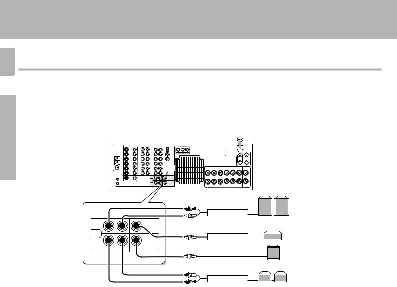
PRE OUT connections
This receiver has additional preout jacks. These can be used for various purposes, but will need to be connected to an external power amplifier as shown in the example below. Connecting a speaker cord directly to a PRE OUT jack will not produce any sound from the speaker.
Be sure to set the SPEAKERS A key to the ON position when using the PRE OUT jacks in Room A.
No sound is output from the SUBWOOFER jack when the SPEAKERS A key is set to the OFF position.
|
|
Front Speakers |
|
|
Power amp |
FRONT |
CENTER |
|
PRE |
|
Center Speaker |
OUT |
|
|
|
|
Power amp |
SURROUND |
SUB WOOFER |
Powered |
|
|
Subwoofer |
|
|
Surround speakers |
|
|
Power amp |
Setting up the system
KR-V999D (En/T)
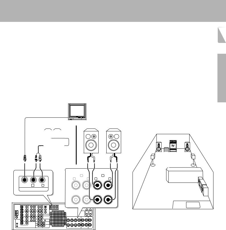
Making connections to another room (ROOM B) |
1 5 |
|
The following connections allow you to connect your main system to a monitor TV and speaker system located in another area (ROOM B). The monitor TV can be connected directly to the SECOND ROOM PRE OUT VIDEO jack. To connect the speakers, use either of the connections described below.
To select the input and adjust the volume (etc.) for your other area (ROOM B), set the remote control to the ROOM B operation mode. u
FRONT SPEAKERS B connections (1):
These connections allow you to connect the speakers in ROOM B directly to the receiver without using an additional power amplifier. The sound from the main system (ROOM A) automatically switches to stereo when SPEAKERS B are turned on.u
Monitor TV
SECOND ROOM PRE OUT connections (2):
Use these connections if you want to enjoy surround sound from your main system (ROOM A) while outputting another source to ROOM B. Connecting a speaker cord directly to a SECOND ROOM PRE OUT jack will not produce any sound from the speaker. Connect the SECOND ROOM PRE OUT jacks to powered speakers or power amplifiers connected to speakers.
Preparations
Speakers (2) |
Speakers (1) |
|||||||
|
|
|
|
|
|
|
|
|
|
|
|
|
|
|
|
|
|
|
|
|
|
|
|
|
|
|
|
|
|
|
|
|
|
|
|
Power amp
· |
ª ª |
· |
ROOM A |
(Main System) |
|||
FRONT SPEAKERS (4−16 Ω) |
|
|
|
A |
B |
|
|
R |
L R |
L |
|
VIDEO R AUDIO L |
|
+ |
|
SECOND ROOM PRE OUT
ROOM B
−
Operations
Other
Setting up the system
KR-V999D (En/T)
1 6 Preparing the remote control
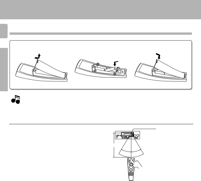
Loading the batteries
1 Remove the cover. 2 Insert the batteries. 3 Close the cover.
Preparations
Notes
•Insert four AAA-size (LR03) batteries as indicated by the polarity markings.
1.The supplied batteries may have shorter lives than ordinary batteries due to use during operation checks.
2.Replace all four batteries with new ones when you notice a shortening of the distance from which the remote control will operate or if the remote control blinks 5 times when you push a key. The remote control is designed to retain set up codes in memory while you change batteries.
3.Placing the remote sensor in direct sunlight, or in direct light from a high frequency fluorescent lamp may cause a malfunction. In such a case, change the location of the system installation to prevent malfunction.
Operations
Operating distance
This remote control has two IR emitters: one to send commands in a straight line over long distances, allowing you to control the receiver and your other components from farther away; and one for wide dispersion of commands in a closer proximity, for nearfield operation even when the remote control is not pointed directly at the respective component.
Remote sensor
6 m
10 m
30˚ 30˚
Model: RC-R0905
Infrared ray system
Other
Preparing for surround sound
This receiver incorporates an on screen display (OSD) feature to simplify the surround setup procedure by providing large easy to read graphic information.
The section below shows you how to operate the on-screen display. Read this first before going on to the surround setup procedures on the following pages.
Preparations • Set the POWER key to ON.
•Set the ON/STANDBY key to ON.
•Turn on your monitor TV.
POWER |
|
MACRO |
SHIFT |
|
AUDIO |
VIDEO |
TV |
8
P. CALL |
|
P. CALL |
4 |
BAND |
¢ |
6 |
||
|
7 |
|
REC |
|
GUIDE |
TUNING/SKIP |
|
VOLUME |
|
MUTE |
|
|
LISTEN |
|
SUBWOOFER |
MODE |
SOUND |
FUNCTION |
|
SETUP |
SHIFT |
|
|
MENU |
THEME |
FAV |
1 |
2 |
3 |
TV/SAT/VID |
INFO |
ALT AUD |
4 |
5 |
6 |
+100 |
REPEAT |
RANDOM |
7 |
8 |
9 |
ROOM A |
DISPLAY |
ROOM B |
+10 |
0 |
ENT |
KR-V999D (En/T)
Keys or controls used in this operation.
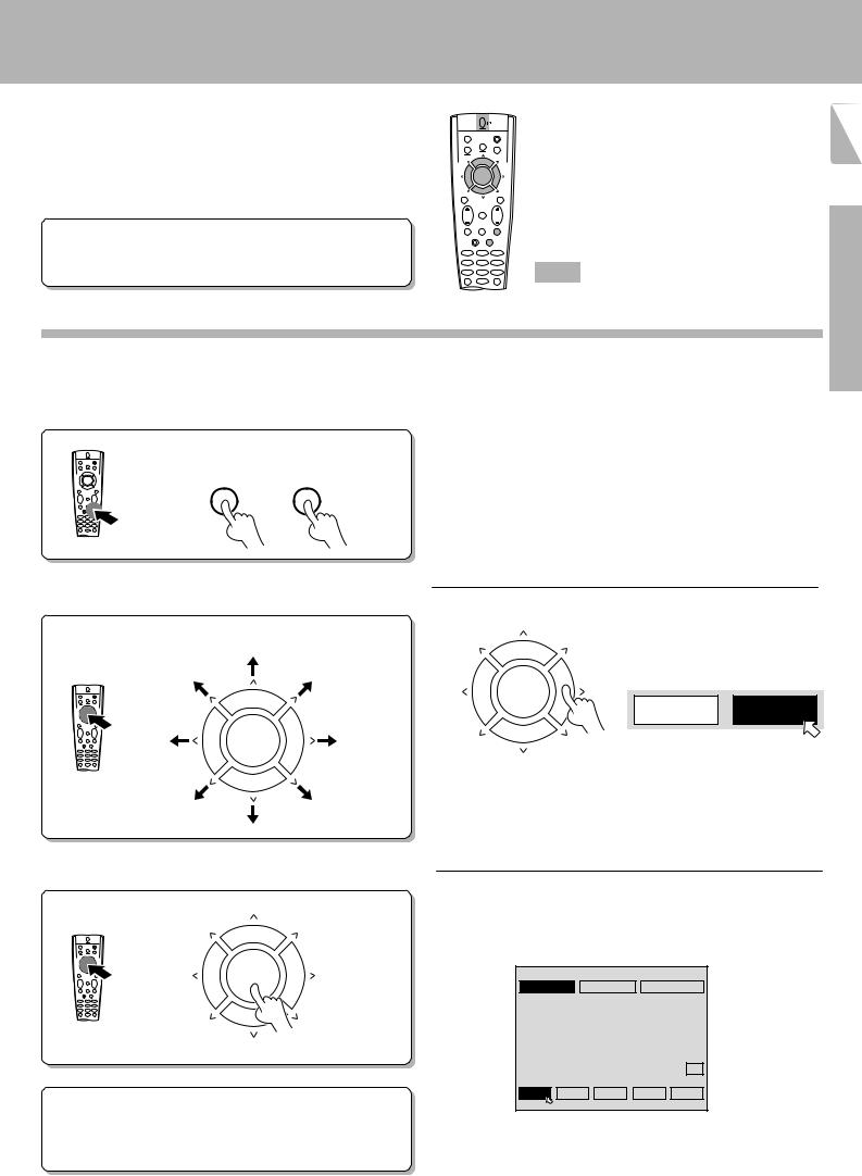
Using the on-screen display
On-screen operations consist of moving the arrow icon to select items from the screen.
1 7
Preparations
1Press the SOUND or SETUP key.
Pressing either the SOUND or SETUP key automatically activates the on-screen display
SOUND
SETUP
2Move the pointer.
It can be moved in 8 directions, depending on how you press the keys
P. CALL |
8 |
P. CALL |
BAND
4 6 ¢
7
•The remote control automatically switches to OSD remote control mode when an on-screen display appears in your monitor TV.
EXAMPLE: moving the pointer to an icon at right.
8 |
P. CALL |
EXAMPLE: when the pointer is |
|
P. CALL |
|||
|
|
moved to the DSP command. |
|
BAND |
¢ |
|
|
4 6 |
3 STEREO |
DSP |
|
7 |
|
||
|
|
|
|
Press the > key.
•If no icons are located in the direction you pressed, the pointer may move in a different direction to locate the nearest object.
3Press the item you desire.
• To confirm an item, press the BAND (6) key located in the center of the remote control after moving the pointer to the item you want to
select.
8
P. CALL |
P. CALL |
The DSP screen appears.
4 |
BAND |
¢ |
|
|
|
6 |
|
|
|
||
|
|
WALL =MEDIUM ROOMSIZE =MEDIUM |
EFFECT LEVEL= 3 |
||
|
7 |
|
|
|
|
|
|
|
|
|
MAIN |
To quit the OSD mode: |
|
ARENA |
JAZZ CLUB STADIUM |
CHURCH |
THEATER |
|
|
|
|
|
|
1 Press the SOUND or SETUP key again.
2Press either the VIDEO, AUDIO, or TV key to cancel the OSD remote control mode.
Preparing for surround sound
KR-V999D (En/T)
1 8 Surround set up
Preparations
To obtain the best possible enjoyment from the receiver's various surround modes, be sure to complete the surround set up as shown below.
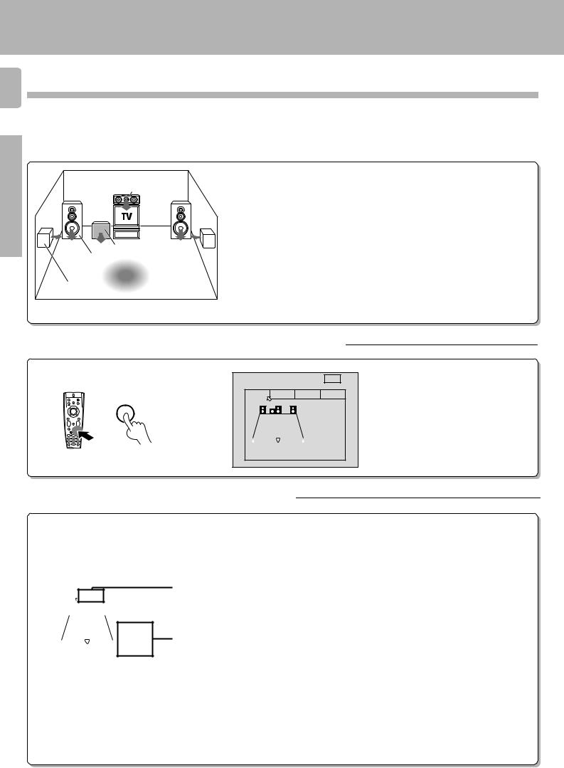
1Speaker placement.
Center speaker
Subwoofer
Front speaker
Listening position
Surround speaker
Front speakers : Place to the front left and right of the listening position. Front speakers are required for all surround modes.
Center speaker : Place front and center. This speaker stabilizes the sound image and helps recreate sound motion. Be sure to connect a center speaker when using the Dolby 3 Stereo mode.
Surround speakers : Place to the direct left and right, or slightly behind, the listening position at even heights, approximately 1 meter above the ears of the listeners. These speakers recreate sound motion and atmosphere. Required for surround playback.
Subwoofer : Reproduces powerful deep bass sounds.
•Although the ideal surround system consists of all the speakers listed above, if you don't have a center speaker or a subwoofer, you can divide those signals between the available speakers in the following steps to obtain the best possible surround reproduction from the speakers you have available.
2Go to the SP.SLCT (speaker select) page of the SET UP screen.
SET UP |
|
|
MAIN |
|
SP.SLCT |
SP.LVL |
|
SP.DIST |
INLVL |
SETUP |
|
|
SPEAKER |
|
|
|
|
||
L |
SW C |
R |
SELECTION |
|
|
|
|
|
SW: ON |
|
|
|
|
|
LR : LRG |
|
|
|
|
|
C |
: LRG |
LS |
|
RS |
|
S |
: LRG |
• Pressing the MAIN icon lets you access the main sound menu. fl
3Select the speakers and enter the speaker distance.
SET UP |
|
|
|
|
|
MAIN |
|
||||||||||
|
|
|
|
|
|
|
|
|
|
|
|
|
|
|
|
|
|
|
|
SP.SLCT |
|
|
SP.LVL |
SP.DIST |
|
INLVL |
|
||||||||
|
|
|
|
|
|
|
|
|
|
|
SPEAKER |
|
|||||
|
|
|
|
|
|
|
|
|
|
|
|
||||||
|
|
|
|
L |
|
SW |
C |
|
R |
SELECTION |
|
||||||
|
|
|
|
|
|
|
|
|
|
|
|
|
SW: ON |
|
|||
|
|
|
|
|
|
|
|
|
|
|
|
|
LR : LRG |
|
|||
|
|
|
|
|
|
|
|
|
|
|
|
|
C |
: LRG |
|
||
|
|
LS |
|
|
|
|
|
|
|
|
RS |
|
S |
: LRG |
|
||
|
|
|
|
|
|
|
|
|
|
|
|
|
|
|
|
|
|
|
|
|
|
|
|
|
|
|
|
|
|
|
|
|
|
|
|
1 Specify the type of speakers you connected to the receiver.
1 Move the pointer downward (icon turns blue).
2 Use the TUNING/SKIP keys to specify the setting you desire.
3 Press the BAND (6) key to confirm the setting (icon turns yellow).
4Repeat steps 2 and 3 to specify a setting for each speaker type.
•Be sure to specify settings for each speaker type before continuing to the next
2screen.
SW : Subwoofer
ON: Select when using a subwoofer.
OFF: Select when not using a subwoofer.
1 |
L R : Front speakers (left and right) |
|
SML (small): Select when using a relatively small front speakers. |
||
|
||
|
LRG (large): Select when using a relatively large front speakers. |
|
|
C : Center speaker |
SML (small): Select when using a relatively small center speaker. LRG (large): Select when using a relatively large center speaker. OFF: Select when not using a center speaker.
S : Surround speakers (left and right)
SML (small): Select when using a relatively small surround speaker. LRG (large): Select when using a relatively large surround speaker. OFF: Select when not using surround speakers.
2 Continue to the SP.LVL (speaker level) screen.
|
Preparing for surround sound |
|
|
|
KR-V999D (En/T) |
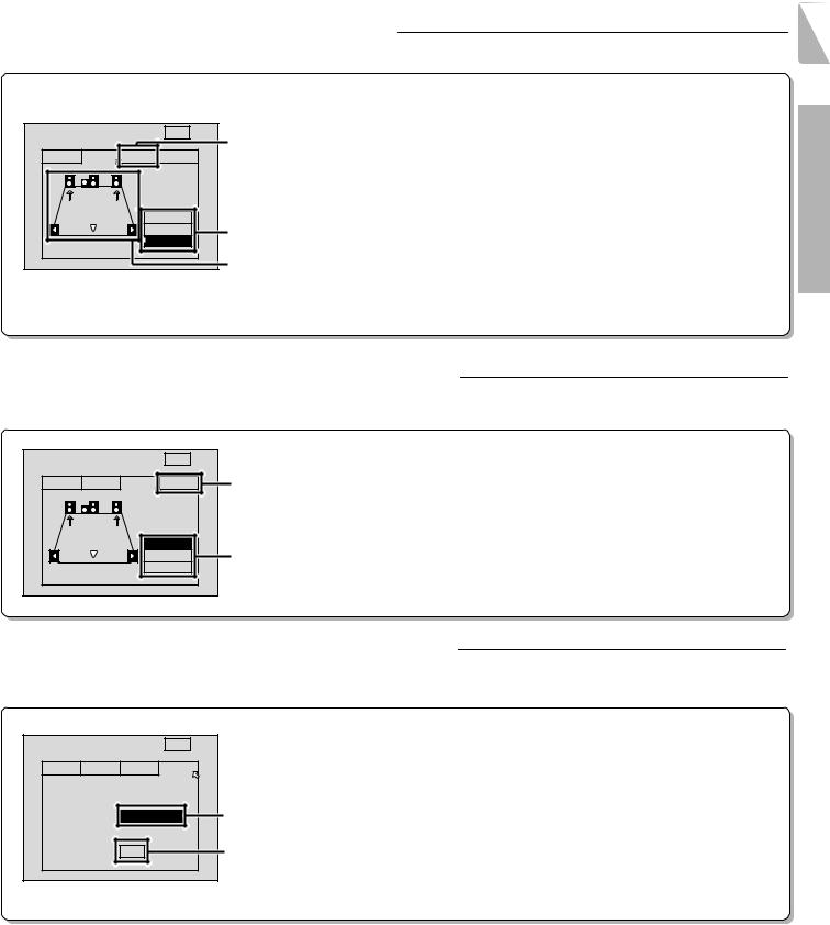
4Adjust the volume levels of each speaker. |
1 9 |
Listen to the test tone and adjust the volume level of each speaker so that they all produce the test tone at the same volume level.
|
|
|
|
|
|
1 Select the test tone type. |
|
|
|
|
|
|
|
AUTO |
: The test tone switches between each speaker in regular intervals. |
SET UP |
|
|
|
MAIN |
3 |
MANUAL : The test tone only comes from the selected speaker (displayed in blue). |
|
|
|
|
OFF |
: Stops the test tone. |
|||
|
|
|
|
|
|||
SP.SLCT |
SP.LVL |
SP.DIST |
INLVL |
|
|||
|
2 Adjust the Volume level of each speaker. |
||||||
|
|
|
SPEAKER |
|
|||
|
|
|
|
1Listen to the test tone and select the speaker you want to adjust. |
|||
|
|
|
LEVEL |
|
• The selected speaker icon turns blue and the speaker name and level appear (at the bottom of |
||
|
|
|
|
TEST TONE |
|
||
|
|
|
AUTO |
|
the screen) to show that it can be adjusted. |
||
|
|
|
MANUAL |
1 |
2Listen to the test tone and adjust the volume level of the speaker (± 10 dB) using the |
||
L = |
0dB |
OFF |
|
TUNING/SKIP keys on the remote control. |
|||
|
|
2 |
TUNING/SKIP – : Lowers the volume TUNING/SKIP + : Raises the volume |
||||
|
|
|
|
|
|||
• Adjust the subwoofer as you desire.
3 Continue to the SP.DIST (speaker distance) screen.
Preparations
5Enter the speaker distance.
Enter the distance from your listening position to the front (left or right), center, and rear (left or right) speakers. If both front (or rear) speakers are not the same distance from the listening position, enter the distance to the closest speaker.
SET UP |
MAIN |
|
1 |
|
|
||
SP.SLCT SP.LVL SP.DIST |
INLVL |
3 |
2 |
SPEAKER
DISTANCE
|
FRONT |
1 |
|
|
CENTER |
3 |
|
|
SURR. |
|
|
10ft |
3. 0m |
|
|
Select the speaker.
The speaker name turns blue. An arrow icon appears to indicate the selected speaker.
Enter the speaker distance.
Use TUNING/SKIP on the remote control to select the appropriate distance.
The distance is adjustable from 0.0meters (0 feet) to 9.0meters (30 feet) in 0.3meter (1 foot) steps.
Continue to the IN LVL (input level) screen.
6Adjust the audio input level of the connected components.
The LEVEL INDICATOR lights during playback if the signal being input from an analog source is too large. If this occurs, use this screen to attenuate the input level for that source.
SET UP |
MAIN |
SP.SLCT SP.LVL SP.DIST |
INLVL |
INPUT LEVEL
SELECTOR: TUNER |
LEVEL |
: |
0dB |
1 Select the input.
1 Use TUNING/SKIP on the remote control to select the desired input. 2 Move the pointer downward.
2 Select an input level.
The input level is adjustable in 3 levels. Use TUNING/SKIP on the remote control to select the
1smallest level required to extinguish the LEVEL INDICATOR (normally, set to 0 dB). 0 dB Ô –3 dB Ô –6 dB
23 Press the SETUP key on the remote to turn off the on-screen display.
4 Press either VIDEO, AUDIO, or TV key on the remote to cancel the OSD remote control mode.
This completes the surround setup.
|
Normal playback |
2 0 |
Preparations • Turn on the power to the related compo- |
|
nents. |
|
• Set the POWER key to the ON position. |
|
POWER |
|
-ON –OFF |
KR-V999D (En/T)
POWER |
|
MACRO |
SHIFT |
|
AUDIO |
VIDEO |
TV |
|
8 |
AUDIO−VIDEO SURROUND RECEIVER KR-V999D |
P. CALL |
P. CALL |
|
BAND |
|
|
|
|
|
|
|
|
|
|
|
|
|
|
|
DOLBY |
|
|
|
|
4 |
6 |
¢ |
|
|
|
|
|
|
|
|
|
|
|
|
|
|
|
|
|
|
|
|
|
|
|
|
|
|
|
|
|
|
|
|
|
|
|
|
3 STEREO |
|
STEREO |
|
|
|
7 |
|
|
|
|
|
|
2-CH |
|
LEVEL |
|
|
|
|
|
|
|
|
INPUT SELECTOR |
VOLUME CONTROL |
|
REC |
GUIDE |
|
BASS |
|
TREBLE |
STANDBY DOWNMIX INDICATOR |
|
|
|
|
|
|
SOURCE DIRECT |
DSP |
|
|
|||||
|
|
|
|
FLAT |
|
FLAT |
1 |
2 |
3 |
4 |
5 |
6 |
7 |
8 |
9 |
0 |
+10/ |
|
|
|
|
|
|
|
|
|
|
|
PTY SEARCH |
|
LOUDNESS |
|
|
||||||||||
|
|
|
|
|
|
|
|
|
|
|
|
|
|
|
|
|
DIMMER |
|
|
|
|
TUNING/SKIP |
|
VOLUME |
|
|
|
|
|
|
|
|
|
|
|
|
|
|
|
|
|
|
|
|
MUTE |
ON/STANDBY |
−10 |
+10 |
−10 |
+10 |
DIRECT |
MEMORY |
|
AUTO |
|
BAND |
|
|
|
TUNING |
MUTE |
TAPE 2 MONITOR |
|
|
|
|
|
POWER |
|
|
|
|
|
|
|
|
|
|
|
|
|
|
|
|
|
|
|
|
|
|
|
|
|
|
|
|
|
|
|
|
|
|
|
|
|
|
|
DOWN |
UP |
|
|
-ON –OFF |
|
|
|
|
|
|
|
|
|
|
|
|
|
|
|
|
|
AV AUX |
|
|
LISTEN |
PHONES |
|
|
|
|
|
|
|
|
|
|
|
|
|
|
|
|
|
|
|
SUBWOOFER |
MODE |
SOUND |
|
|
|
|
|
|
|
|
|
|
|
|
|
|
|
|
|
|
|
|
|
T R A I T R |
A SPEAKERS B TA/NEWS/INFO. PTY DISPLAY |
|
|
|
S−VIDEO VIDEO L - AUDIO - R |
FUNCTION |
|
SETUP |
|
SHIFT |
|
|
|
MENU |
THEME |
FAV |
|
1 |
2 |
3 |
|
TV/SAT/VID |
INFO |
ALT AUD |
|
4 |
5 |
6 |
|
+100 |
REPEAT |
RANDOM |
Keys or controls used in this operation. |
ROOM A |
DISPLAY |
ROOM B |
|
7 |
8 |
9 |
|
+10 |
0 |
ENT |
|
Listening to a source component
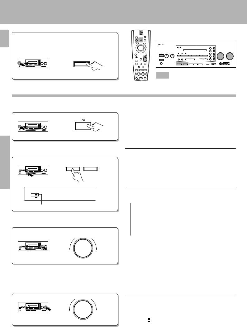
1Turn on the receiver.
ON/STANDBY
Operations |
2Set SPEAKERS A to on. |
|
|
A SPEAKERS |
B |
||
|
SP. A B A-PHONO
ROOM A B
The speaker A indicator should be lit.
3Select the source you desire.
INPUT SELECTOR
4Start playback from the selected source.
5Adjust the volume.
VOLUME CONTROL
DOWN |
UP |
Decrease volume |
Increase volume |
•Surround modes cannot be activated when both SPEAKERS A and SPEAKERS B are set to ON. For details on the SPEAKERS B button,
see "Controlling the sound in another room (ROOM B)". |
u |
•Be sure to set the SPEAKERS A key to the ON position when using the PRE OUT jacks in Room A. No sound is output from the SUBWOOFER jack when the SPEAKERS A key is set to the OFF position.
The input sources change as shown below:
 1 TUNER (Frequency display)
2 "PHONO"("PHONO"*)
3 "VIDEO1" ("SAT"*)
4 "VIDEO2" ("LD"*)
5 "VIDEO3" ("VCR"*)
6 "VIDEO4" ("DSS"*)
7 "AV AUX"
8 "CD" ("CD"*)
 9 "TAPE1/MD" ("TAPE"*)
* Once setup codes are registered in the remote control, the input name display changes according to the name of the registered component. Example: if you register a VCR at the VIDEO 1 jacks, "VCR1" appears instead of "VIDEO 1". ‚
•Both the default input name and the component type (i.e., " VIDEO1 'VCR1' ") are shown in the on screen display when the OSD mode is
set to ON. |
° |
•When using the remote control after initial setup, any inputs that have not been registered with a setup code are deleted from the cyclic list
(except for the "AV AUX" VIDEO input). |
w |
•The INPUT SELECTOR on the front panel of the receiver always cycles through all inputs.
|
Volume display |
|
|
|
|
|
|
|
|
|
|
ROOM A |
V-A -6) dB |
|
SP. A |
|
|
|
|
|
 Loading...