


Kenwood HTB-S710DV Manual

HTB-S710DV
Congratulations!
The HTB-S710DV Kenwood Fineline™ Gaming Home Theater System will make enjoying video games, movies and music at home more fun than ever. This sheet will show you how to connect your speakers and DVD player to the receiver, and how to operate the HTB-S710DV’s unique gaming features. To learn how to operate your receiver and DVD player, please read and follow the instruction manuals included in their boxes. If you’re also connecting other equipment, such as a TV, VCR, satellite tuner or other source component, use the receiver’s manual in combination with the manuals that came with those components.
Assembling the speaker stands
Important: Do not connect the speaker wires to the receiver until after you have completely assembled the stands.
1. Using the short screws, attach the stand |
Step 1 |
rail to the base as shown. |
• The open side of the rail faces the rear of base
• Tighten the screws snugly, but do not over-tighten them.
2. Feed approx. 12” of speaker wire up through the hole in the base.
•Use the wire with the white bands for the left speaker; use the wire with the red bands for the right speaker (see large illustration).
3.Tilt the base on a flat surface with the open side of the rail facing up.
4.Slip the gray spacer into the rail as shown.
•Correct orientation of the gray spacer is important — the screws will only fit if the spacer is inserted correctly.
5.Bring the speaker wire through the oval holes in both the gray and white spacers as shown.
•Correct orientation of the white spacer is important — the screws will only fit if the spacer is oriented correctly. The ridge in the white spacer fits into the groove in the rail.
6.Connect the speaker wire to the speaker: Hold the connectors open, insert the bare portions of the wire all the way into the openings and release the connectors.
•Make sure the wires do not touch each other — touching wires will cause a short circuit that could damage the receiver.
•Insert the wire with the white stripe into the red connector; insert the plain wire into the black connector
7.Gently pull the excess wire back through the spacers and place the rail/spacer assembly against the speaker, aligning the holes in both spacers with the holes in the speaker.
•Make sure you don’t disconnect the wires from the speaker.
•The ridge in the white spacer fits into the groove in the rail.
Step 4 |
Step 5 |
Step 7 |
8. Insert the large screws through the holes in both spacers and tighten them snug-
ly into the speaker, as shown. Don’t overtighten the screws.
9.Stand the speaker upright and gently pull the excess speaker wire through the hole in the base. Slip the wire cover into the small groove in the top of the rail and slide it all the way down into the rail, as shown.
10.Fit the cap on the top of the rail.
To adjust the height of the speaker on the stand, remove the cap and wire cover, loosen the screws and move the speaker along the rail, then re-tighten the screws.
Step 8 |
Speaker Connections
• Make sure |
you |
don’t disconnect the |
Step 9 |
|
wires from |
the |
speaker when you’re |
||
|
||||
adjusting the height. |
|
|||
Placing Your Speakers
Place the speakers as shown in the diagram below. While you’re setting the speakers up, keep these points in mind:
• If the subwoofer causes discoloration of the TV picture, move it away from the TV until the discoloration disappears.
•Since the center speaker is magnetically
shielded, you can place it right on top of  the TV without worrying about picture discoloration.
• You can hang the speakers on the wall using heavy-duty picture hangers.
• |
Placing the subwoofer next to a wall yields more deep bass output than placing |
COMPONENT |
|
|
|
|
|
COMPONENT |
|
|
|
|
|
|
|
|
|
|
it away from a wall. Placing the subwoofer in a corner yields the deepest bass |
VIDEO |
|
|
|
|
|
VIDEO |
|
|
|
|
|
|
|
SPEAKERS (6 – 8Ω ) |
|
|
|
OUTPUT |
|
|
|
|
|
INPUT |
|
|
|
|
|
|
|
|
|
|
output overall. |
ASSIGNABLE |
ANTENNA |
CR |
|
|
ASSIGNABLE |
IN2 |
|
|
|
|
OUT |
|
+ |
+ |
|
|
|
|
DIGITAL IN ASSIGNABLE |
IN1 |
VIDEO IN |
VIDEO IN |
VIDEO OUT |
VIDEO IN |
|
||||||||
|
|
|
Y |
CB |
|
|
|
MONITOR |
|
|
|
||||||
|
|
|
|
|
|
COAX 2 |
OPT 1 |
OPT 2 |
|
|
|
|
|
|
|
|
|
|
|
|
|
|
|
|
Y |
CB |
CR |
|
|
|
|
|
|
|
|
|
|
|
|
|
|
|
|
|
|
|
|
L |
– |
– |
|||
|
|
|
|
|
|
|
|
|
|
|
|
|
|
|
|||
|
|
FM 75Ω |
|
GND |
AM |
COAX 1 |
|
|
|
|
|
|
|
|
|
|
|
SUB |
|
|
|
R |
R FRONT L |
CENTER SURR BACK |
R SURR L |
WOOFER SURROUND BACK |
IN |
PLAY IN |
REC OUT PLAY IN |
IN |
|
/SW |
|
|
|
|
|||||
PRE OUT |
DVD |
VIDEO 2 |
VIDEO 1 |
AUX |
|
|
|
Connecting Your Speakers
Important: Do not plug the receiver’s power cord into an AC outlet until you have properly connected all of the speakers.
Connect the speakers as shown in the large diagram to the right.
To make connecting the speakers easier, we have color-coded the speakers, speaker wire and terminals on the receiver, and pre-stripped the insulation from the ends of the wires.
Connect the speaker wire with the colored bands to the correspondingly colored terminals on the speaker and receiver.
Important: Insert the wires with the white stripes into the colored connectors; insert the plain wires into the black connectors.
(continued on other side)
If you have any questions about your new system, please contact our Customer Service Department at (800) KENWOOD or visit our web site at www.kenwoodusa.com
Kenwood Fineline™ Quick Start Guide
Copyright ©2004 Kenwood USA Corporation. All rights reserved.
(continued from other side)
DO NOT PUSH THE WIRE TOO FAR INTO THE SPEAKER TERMINALS AS THIS WILL NOT ALLOW THE WIRE TO MAKE PROPER CONTACT.
The subwoofer connects to the receiver using the audio cable:
•Connect one end of the audio cable to the input connector on the subwoofer labeled LINE INPUT, and connect the other end to the connector on the receiver labeled SUB
WOOFER PRE OUT.
Using Your Subwoofer
Subwoofer Volume Control
Initially, set the subwoofer’s volume knob to the 11 o’clock position. During normal operation you will use the receiver’s subwoofer volume control to adjust the subwoofer volume. If the receiver’s subwoofer volume control won’t go loud or soft enough, re-adjust the subwoofer’s volume knob to compensate. See the receiver’s instruction manual for details on using the receiver’s subwoofer volume control.
Balancing the Speakers
Your receiver comes with the speaker volume settings pre-balanced. If you have positioned the speakers as shown in the diagram your system will create a spacious surround sound environment right out of the box with no further adjustment required.
If your room is arranged differently than shown in the diagram, or if you simply want to fine-tune your system’s performance, you can easily change the volumes of the individual speakers to get a better balance:
1.Press the SETUP button once. The display will read “SP SETUP”.
2.Press the > MULTI CONTROL button once. The display will change to “SP LEVEL”.
3.Press the ENTER button once. The display will read “TEST TONE” and then change to “AUTO”.
4.Press the > MULTI CONTROL button once again. The display will read “MANUAL”.
5.Press the ENTER button repeatedly until the speaker you want to adjust appears on the display. The speaker’s icon will flash and you will hear test noise through the speaker.
6. Use the>and >MULTI CONTROL buttons to increase and decrease the speaker’s volume.
7.Do not be concerned with the volume level readout on the display while you’re adjusting the speakers—this is for reference purposes only. However, once you have balanced all the speakers you should write each speaker’s volume setting down here for reference:
LEFT |
RIGHT |
CENTER |
LEFT |
RIGHT |
SURROUND |
SUB- |
FRONT |
FRONT |
|
SURROUND |
SURROUND |
BACK |
WOOFER |
8. Press the SETUP button once more to exit the setup mode.
Setting the Speaker Distances
This last step adjusts the timing of all the speakers so that their sound arrives at the listening location at the proper time.
1.Measure the distance from each speaker to your seat. Write the distances down.
2.Press the SETUP button once. The display will read “SP SETUP”.
3.Press the > MULTI CONTROL button twice. The display will change to “DISTANCE”.
4.Press the ENTER button once. The display will read “METERS”. Press the >’MULTI CON- TROL button once to change the units to feet (the display will change to “FEET”).
5.Press the ENTER button once. The display will read “L 10FT” and the left speaker icon will flash.
6. Press the>or >MULTI CONTROL buttons until the distance on the display matches the distance from your left speaker to your listening position.
7.Press the > MULTI CONTROL button again to repeat Step 6 for the center speaker, and then for the rest of the system’s speakers.
8.When you’ve finished setting the speaker distances, press the SETUP button to exit
the setup mode.
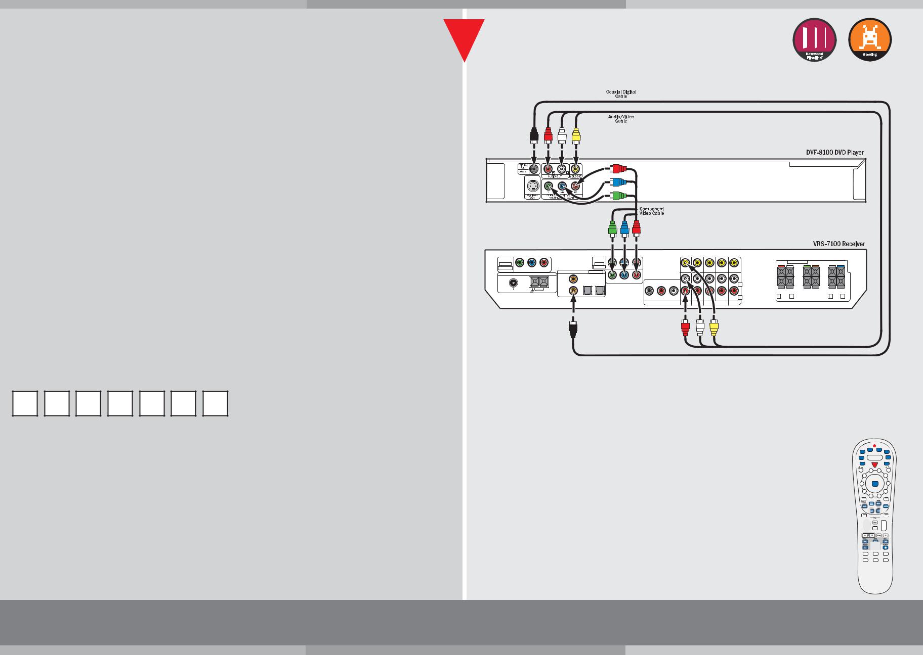
Connecting the DVD Player to the Receiver
Connect the DVD player to the receiver as shown in the large diagram to the right, using the cables supplied with the DVD player.
Coaxial Digital Cable
The coaxial digital cable (black) carries the Dolby Digital and DTS digital audio bitstreams to the receiver for decoding.
Audio and Composite Video Cables
The audio and composite video cables carry the standard analog audio and composite video signals to the receiver. Use the red wire for the right audio channel, the white wire for the left audio channel and the yellow wire for the video connection.
Component Video Connections
If you are using your HTB-S710DV with an HD-capable TV or monitor you can use an optional Component Video cable to connect the DVD player to the receiver for improved video quality over the standard composite video connection. If you use a Component Video cable to connect the DVD player to the receiver you must also use a Component Video cable to connect the receiver to the TV or monitor.
Connecting a Video Game to the Front-Panel Game Input
Your HTB-S710DV receiver has a set of inputs specially-designed for video games. The inputs are located behind a flip-down door on the receiver’s front panel.
•Connect your game console’s video and audio outputs to the inputs labeled “GAME” (see diagram to the right).
Once the console is connected you need to set up the GAME input:
1.Press the SETUP button to enter the setup mode.
2.Press the > MULTI CONTROL button 5 times. The display will read “GAME FUNC”.
3.Press the ENTER button. The display will change to “MODE 1”. MODE 1 activates the following functions:
•The receiver will detect whenever the game console is turned on and will automatically switch its input to GAME.
•The receiver will automatically activate special EQ circuitry (Active EQ — EQ GAME) that is designed to enhance game sounds.
•The listen mode will automatically switch to Dolby Pro Logic IIx: Game, or the appropriate digital surround mode. (Note: If you change to a different listen mode, that mode will be automatically activated the next time you select the GAME input.)
4.Press the> MULTI-CONTROL button to change to “MODE 2”. In MODE 2 the receiver will detect whenever the game console is turned on and will automatically switch its input to GAME.
5.Press the> MULTI CONTROL button to change to “OFF”, which bypasses all of MODE 1 and MODE 2’s special functions.
6.Select either MODE 1, MODE 2 or OFF, then press ENTER to register your selection.
7.Press SETUP to exit the setup mode.
Using the Dual-Source/Single-Zone mode
You can listen to a game soundtrack through headphones while others listen to music through the system’s speakers.
1.Connect a pair of stereo headphones to the HEADPHONES jack.
2.Press the DUAL SOURCE ON/OFF button. The Dual Source icon will illuminate.
3.Press the DUAL SOURCE INPUT button to select either the GAME input or the F. AUX input sound for the headphones.
•Video from the selected input will show on a connected TV or monitor.
4. Use the DUAL SOURCE VOLUME>/>buttons to adjust the headphone volume.
The source selected by the receiver’s main Input Selector will play through the speakers; its volume will be controlled by the receiver’s Volume Control knob.
• If a video source is selected, its video will NOT show on a connected TV or monitor.
To exit the Dual-Source/Single-Zone mode and return to normal operation, press the DUAL SOURCE ON/OFF button so the Dual Source icon is not illuminated.
If you have any questions about your new system, please contact our Customer Service Department at (800) KENWOOD or visit our web site at www.kenwoodusa.com
HTB-S710DV
DVD Player Connections
COMPONENT |
|
|
|
|
|
|
COMPONENT |
|
|
|
|
|
|
|
|
|
|
|
|
|
|
VIDEO |
|
|
|
|
|
|
VIDEO |
|
|
|
|
|
|
|
|
SPEAKERS (6 – 8Ω ) |
|
|
|
|
|
OUTPUT |
|
|
|
|
|
|
INPUT |
|
|
|
|
|
|
|
|
|
|
|
|
|
|
ASSIGNABLE |
Y |
CB |
CR |
|
|
|
ASSIGNABLE |
IN2 |
|
|
|
|
|
|
MONITOR |
|
+ |
+ |
|
|
|
|
|
|
|
|
IN1 |
|
|
VIDEO IN |
VIDEO IN |
VIDEO OUT |
VIDEO IN |
|
|
|
|
||||||
|
|
DIGITAL IN |
ASSIGNABLE |
|
|
OUT |
|
|
|
|
|||||||||||
|
ANTENNA |
|
|
|
|
|
|
|
|
|
|
|
|
|
|
|
|
|
|
|
|
|
|
|
|
COAX 2 |
OPT 1 |
OPT 2 |
|
|
|
|
|
|
|
|
|
|
|
|
|
|
|
|
|
|
|
|
|
Y |
CB |
CR |
|
|
|
|
|
|
|
|
|
|
|
|
|
|
|
|
|
|
|
|
|
|
|
|
|
L |
|
– |
– |
|
|
|
|||
|
|
|
|
|
|
|
|
|
|
|
|
|
|
|
|
|
|
|
|||
FM 75Ω |
|
GND |
AM |
COAX 1 |
|
|
|
|
|
|
|
|
|
|
|
|
|
|
|
|
|
|
|
|
|
|
|
|
|
|
SUB |
|
|
|
|
|
R |
R FRONT L |
CENTER |
SURR BACK |
R |
SURR |
L |
|
|
|
|
|
|
|
|
|
WOOFER |
SURROUND BACK |
IN |
PLAY IN |
REC OUT PLAY IN |
IN |
|
|
/SW |
|
|
|
|
|
|
|
|
|
|
|
|
|
|
PRE OUT |
DVD |
VIDEO 2 |
VIDEO 1 |
AUX |
|
|
|
|
|
|
|
|
|
|
|
Game Connections |
|
FRONT AUX |
DIGITAL IN |
GAME |
Connect the game |
PHONES |
VIDEO L AUDIO R |
(OPTICAL) |
VIDEO L AUDIO R |
console to these inputs: |
Controlling the DVD Player with the Receiver Remote
The receiver’s remote comes pre-programmed ready to control the DVD player included with your HTB-S710DV system.
To operate the DVD player with the receiver’s remote, press the DVD button, then press the button for the operation you want to perform, as shown in the diagrams to the right:
DVD button |
Activates the menu |
||
DVD power ON/OFF |
system |
||
Changes the Audio |
|||
Numeric |
|||
Mode |
|||
entry buttons |
|
|
|
Cursor and |
Changes the |
||
selection controls |
Camera Angle |
||
Activates the |
Activates the |
||
Subtitle function |
|||
On-Screen Display |
|||
|
|||
Pages down or up |
Skip tracks |
||
|
|||
|
DVD transport controls: |
||
Activates the |
>> = Search Forward |
||
<< |
= Search Backward |
||
Top (title) menu |
|||
>/ll= Play |
|||
|
|||
|
ll |
= Pause |
|
|
|
= Stop |
|
Kenwood Fineline™ Quick Start Guide
Copyright ©2004 Kenwood USA Corporation. All rights reserved.
 Loading...