


SERVICE MANUAL
DUAL SIZED CD RECEIVER
WA063<Rev.003>201310SERVICE MANUALB53-0993-20
DPX-U5130, DPX-U5130BT, DPX300U,
DPX305U, DPX405BT, DPX500BT,
DPX5130BTPT4, DPXU5130MM3
DPX-U5130 (Korea) : H1
DPX-U5130 (Other Areas) : M2
DPX5130BTPT4 (TOYOTA in Philippines) : M3
DPXU5130MM3 (MITSUBISHI in Malaysia) : M4
Mounting hardware assy
(J22-0429-23)
Compact disc
(W01-2054-05)
COPYRIGHT © 2013 JVC KENWOOD Corporation
B53-0993-20
DC cord
(E30-6939-05)
Screw set
(N99-18xx-05)
COPYRIGHT © 2013 JVC KENWOOD Corporation
DC cord
(E30-6940-15)
Lever
(D10-7012-04) x2
DC cord
(E30-8314-05)
Escutcheon
(B07-3379-02)
This product complies with the RoHS directive for the European market.
Microphone (3m)
(QAN0126-001)
Escutcheon
(B07-338x-01)
This product uses Lead Free solder.
Remote control unit
(RC-406)
(QAL1303-004)
Spacer (for old NISSAN)
(J30-1106-04) x2
PbF
No.WA063<Rev.003>
2013/10
SPECIFICATION
Models for destination "K" (DPX300U, DPX500BT)
FM tuner section
Frequency range (200 kHz step) 87.9 - 107.9 MHz
Usable sensitivity (S/N= 30 dB) 9.3 dBf (0.8 µV/75 Ω)
Quieting sensitivity (DIN S/N = 46 dB) 10.2 dBf (1.13 µV/75 Ω)
Frequency response (± 3 dB) 30 Hz - 15 kHz
Signal to noise ratio (MONO) 75 dB
Stereo separation (1 kHz) 45 dB
AM tuner section
Frequency range (10 kHz step) 530 kHz - 1 700 kHz
Usable sensitivity (S/N= 20 dB) 28 dBµ (25 µV)
CD player section
Laser diode GaAIAs
Digital filter (D/A) 8 Times Over Sampling
D/A converter 24 Bit
Spindle speed (Audio files) 500 - 200 rpm (CLV)
Wow & Flutter Below Measurable Limit
Frequency response (± 1 dB) 20 Hz - 20 kHz
Total harmonic distortion (1 kHz) 0.01%
Signal to noise ratio (1 kHz) 105 dB
Dynamic range 90 dB
MP3 decode Compliant with MPEG-1/2 Audio Layer-3
WMA decode Compliant with Windows Media Audio
AAC decode AAC-LC ".m4a" files
USB interface
USB standard USB1.1/ 2.0 (Full speed)
File system FAT12/16/ 32
Maximum supply current DC 5 V 1 A
MP3 decode Compliant with MPEG-1/2 Audio Layer-3
WMA decode Compliant with Windows Media Audio
AAC decode AAC-LC ".m4a" files
WAV decode Linear-PCM
Bluetooth section (DPX500BT only)
Version Bluetooth Ver. 2.1+EDR Certified
Frequency Range 2.402 - 2.480 GHz
Output power +4 dBm (MAX), 0 dBm (AVE) Power Class 2
Maximum Communication range Line of sight approx. 10m (32.8 ft)
Profile HFP (Hands-Free Profile), SPP (Serial Port Profile), PBAP (Phonebook Access
Profile), OPP (Object Push Profile), A2DP (Advanced Audio Distribution Profile),
AVRCP (Audio/Video Remote Control Profile)
Audio section
Maximum output power 50 W × 4
Full Bandwidth Power (at less than 1% THD) 22 W × 4
Speaker impedance 4 - 8 Ω
Tone action Bass 100 Hz ± 8 dB
Middle 1 kHz ± 8 dB
Treble 12.5 kHz ± 8 dB
Preout level / load (CD) 2500 mV/10 kΩ
Preout impedance ≤ 600 Ω
Auxiliary input
Frequency response (± 3 dB)
Input maximum voltage 1200 mV
Input impedance 10 kΩ
General
Operating voltage DPX500BT: 14.4 V (10.5 - 16V allowable)
Maximum current consumption 10 A
Installation size (W × H × D) 182 mm × 111 mm × 157 mm (7-3/16" × 4-3/8" × 6-1/16")
Weight 3.4 lbs (1.5 kg)
Subject to change without notice.
20 Hz - 20 kHz
DPX300U: 14.4 V (11 - 16V allowable)
(No.WA063<Rev.003>)2/31
SPECIFICATION
Models for destination "E" (DPX305U, DPX405BT)
FM tuner section
Frequency range (50 kHz step) 87.5 MHz - 108.0 MHz
Usable sensitivity (S/N= 26 dB) 0.63 µV/75 Ω
Quieting sensitivity (DIN S/N = 46 dB) 1.6 µV/75 Ω
Frequency response (± 3 dB) 30 Hz - 15 kHz
Signal to noise ratio (MONO) 75 dB
Stereo separation (1 kHz) 45 dB
MW tuner section
Frequency range (9 kHz step) 531 kHz - 1611 kHz
Usable sensitivity (S/N= 20 dB) 36 µV
LW tuner section
Frequency range 153 kHz - 279 kHz
Usable sensitivity (S/N= 20 dB) 57 µV
CD player section
Laser diode GaAIAs
Digital filter (D/A) 8 Times Over Sampling
D/A converter 24 Bit
Spindle speed 500 - 200 rpm (CLV)
Wow & Flutter Below Measurable Limit
Frequency response (± 1 dB) 20 Hz - 20 kHz
Total harmonic distortion (1 kHz) 0.01%
Signal-to-Noise ratio (1 kHz) 105 dB
Dynamic range 90 dB
MP3 decode Compliant with MPEG-1/2 Audio Layer-3
WMA decode Compliant with Windows Media Audio
AAC decode AAC-LC ".m4a" files
USB interface
USB standard USB1.1/ 2.0 (Full speed)
File system FAT12/16/ 32
Maximum supply current DC 5 V 1 A
MP3 decode Compliant with MPEG-1/2 Audio Layer-3
WMA decode Compliant with Windows Media Audio
AAC decode AAC-LC ".m4a" files
WAV decode Linear-PCM
Audio section
Maximum output power 50 W × 4
Output power (DIN 45324, +B = 14.4 V)
Speaker impedance 4 - 8 Ω
Tone action Bass 100 Hz ± 8 dB
Middle 1 kHz ± 8 dB
Treble 12.5 kHz ± 8 dB
Preout level / load (CD) 2500 mV/10 kΩ
Preout impedance ≤ 600 Ω
Bluetooth section (DPX405BT only)
Version Bluetooth Ver. 2.1+EDR Certified
Frequency Range 2.402 - 2.480 GHz
Output Power +4 dBm (MAX), 0 dBm (AVE) Power Class 2
Maximum Communication range Line of sight approx. 10m
Profile HFP (Hands-Free Profile), SPP (Serial Port Profile), PBAP (Phonebook Access Profile), OPP
Auxiliary input
Frequency response (± 3 dB)
Input maximum voltage 1200 mV
Input impedance 10 kΩ
General
Operating voltage DPX405BT: 14.4 V (10.5 - 16V allowable)
Maximum current consumption 10 A
Installation size (W × H × D) 182 mm × 111 mm × 157 mm
Weight 1.5 kg
Subject to change without notice.
30 W × 4
(Object Push Profile), A2DP (Advanced Audio Distribution Profile), AVRCP (Audio/Video Remote Control Profile)
20 Hz - 20 kHz
DPX305U: 14.4 V (11 - 16V allowable)
(No.WA063<Rev.003>)3/31
SPECIFICATION
Models for destination "M&H" (DPX-U5130, DPX-U5130BT, DPX5130BTPT4, DPXU5130MM3)
FM tuner section
Frequency range 87.9 MHz - 107.9 MHz (200 kHz space)
87.5 MHz - 108.0 MHz (50 kHz space)
Usable sensitivity (S/N= 26 dB) 7.2 dBf (0.63 µV/75 Ω)
Quieting sensitivity (DIN S/N = 46 dB) 15.2 dBf (1.6 µV/75 Ω)
Frequency response (± 3 dB) 30 Hz - 15 kHz
Signal-to-Noise ratio (MONO) 75 dB
Stereo separation (1 kHz) 45 dB
AM tuner section
Frequency range Band 1 (MW) 530 kHz to 1700 kHz (10 kHz space)
531 kHz to 1611 kHz (9 kHz space)
Band 2 (SW1) 2940 kHz to 7735 kHz (5 kHz space)
Band 3 (SW2) 9 500 kHz - 10135 kHz / 11580 kHz to 18135 kHz (5 kHz space)
Usable sensitivity (S/N= 20 dB) MW: 31 dBµ (36 µV) / SW: 32 dBµ (40 µV)
CD player section
Laser diode GaAIAs
Digital filter (D/A) 8 Times Over Sampling
D/A converter 24 Bit
Spindle speed 500 rpm to 200 rpm (CLV)
Wow & Flutter Below Measurable Limit
Frequency response (± 1 dB) 20 Hz - 20 kHz
Total harmonic distortion (1 kHz) 0.01%
Signal-to-Noise ratio (1 kHz) 105 dB
Dynamic range 90 dB
MP3 decode Compliant with MPEG-1/2 Audio Layer-3
WMA decode Compliant with Windows Media Audio
AAC decode AAC-LC ".m4a" files
USB interface
USB standard USB1.1/ 2.0 (Full speed)
File system FAT12/16/ 32
Maximum supply current DC 5 V 1 A
MP3 decode Compliant with MPEG-1/2 Audio Layer-3
WMA decode Compliant with Windows Media Audio
AAC decode AAC-LC ".m4a" files
WAV decode Linear-PCM
Audio section
Maximum output power 50 W × 4
Full bandwidth power 22 W × 4 (at less than 1 % THD)
Speaker impedance 4 - 8 Ω
Tone action Bass 100 Hz ± 8 dB
Middle 1 kHz ± 8 dB
Treble 12.5 kHz ± 8 dB
Preout level / load (CD) 2500 mV/10 kΩ
Preout impedance ≤ 600 Ω
Bluetooth section (DPX-U5130BT, DPX5130BTPT4 only)
Version Bluetooth Ver. 2.1+EDR Certified
Frequency Range 2.402 - 2.480 GHz
Output Power +4 dBm (MAX), 0 dBm (AVE) Power Class 2
Maximum Communication range Line of sight approx. 10m (32.8 ft)
Profile HFP (Hands-Free Profile), SPP (Serial Port Profile), PBAP (Phonebook Access
Profile), OPP (Object Push Profile), A2DP (Advanced Audio Distribution Profile),
AVRCP (Audio/Video Remote Control Profile)
Auxiliary input
Frequency response (± 3 dB) 20 Hz - 20 kHz
Input maximum voltage 1200 mV
Input impedance 10 kΩ
General
Operating voltage DPX-U5130BT: 14.4 V (10.5 - 16V allowable)
DPX-U5130: 14.4 V (11 - 16V allowable)
Maximum current consumption 10 A
Installation size (W × H × D) 182 mm × 111 mm × 157 mm
Weight 1.5 kg
Subject to change without notice.
(No.WA063<Rev.003>)4/31
SECTION 1
PRECAUTION
1.1 Safety Precautions
(1) This design of this product contains special hardware and
many circuits and components specially for safety purposes. For continued protection, no changes should be made
to the original design unless authorized in writing by the
manufacturer. Replacement parts must be identical to
those used in the original circuits. Services should be performed by qualified personnel only.
(2) Alterations of the design or circuitry of the product should
not be made. Any design alterations of the product should
not be made. Any design alterations or additions will void
the manufacturers warranty and will further relieve the
manufacture of responsibility for personal injury or property
damage resulting therefrom.
(3) Many electrical and mechanical parts in the products have
special safety-related characteristics. These characteristics are often not evident from visual inspection nor can the
protection afforded by them necessarily be obtained by using replacement components rated for higher voltage, wattage, etc. Replacement parts which have these special
safety characteristics are identified in the Parts List of Service Manual. Electrical components having such features
are identified by shading on the schematics and by ( ) on
the Parts List in the Service Manual. The use of a substitute
replacement which does not have the same safety characteristics as the recommended replacement parts shown in
the Parts List of Service Manual may create shock, fire, or
other hazards.
(4) The leads in the products are routed and dressed with ties,
clamps, tubings, barriers and the like to be separated from
live parts, high temperature parts, moving parts and/or
sharp edges for the prevention of electric shock and fire
hazard. When service is required, the original lead routing
and dress should be observed, and it should be confirmed
that they have been returned to normal, after reassembling.
(5) Leakage shock hazard testing
After reassembling the product, always perform an isolation check on the exposed metal parts of the product (antenna terminals, knobs, metal cabinet, screw heads,
headphone jack, control shafts, etc.) to be sure the product
is safe to operate without danger of electrical shock.Do not
use a line isolation transformer during this check.
• Plug the AC line cord directly into the AC outlet. Using a
"Leakage Current Tester", measure the leakage current
from each exposed metal parts of the cabinet, particularly any exposed metal part having a return path to the
chassis, to a known good earth ground. Any leakage current must not exceed 0.5mA AC (r.m.s.).
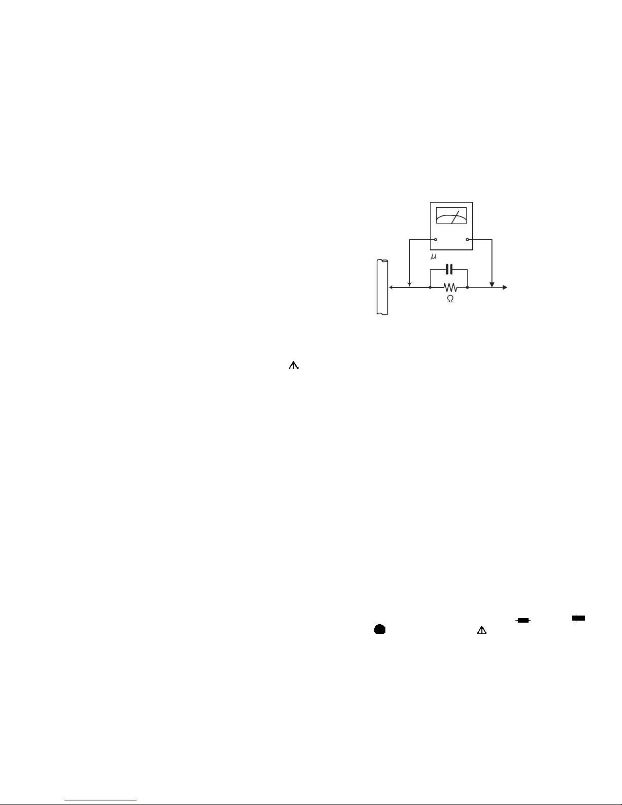
• Alternate check method
Plug the AC line cord directly into the AC outlet. Use an
AC voltmeter having, 1,000Ω per volt or more sensitivity
in the following manner. Connect a 1,500Ω 10W resistor
paralleled by a 0.15µF AC-type capacitor between an exposed metal part and a known good earth ground.
Measure the AC voltage across the resistor with the AC
voltmeter.
Move the resistor connection to each exposed metal
part, particularly any exposed metal part having a return
path to the chassis, and measure the AC voltage across
the resistor. Now, reverse the plug in the AC outlet and
repeat each measurement. Voltage measured any must
not exceed 0.75 V AC (r.m.s.). This corresponds to 0.5
mA AC (r.m.s.).
AC VOLTMETER
(Having 1000
ohms/volts,
or more sensitivity)
0.15 F AC TYPE
Place this
probe on
1500 10W
Good earth ground
1.2 Warning
(1) This equipment has been designed and manufactured to
meet international safety standards.
(2) It is the legal responsibility of the repairer to ensure that
these safety standards are maintained.
(3) Repairs must be made in accordance with the relevant
safety standards.
(4) It is essential that safety critical components are replaced
by approved parts.
(5) If mains voltage selector is provided, check setting for local
voltage.
1.3 Caution
Burrs formed during molding may be left over on some parts
of the chassis.
Therefore, pay attention to such burrs in the case of preforming repair of this system.
1.4 Critical parts for safety
In regard with component parts appearing on the silk-screen
printed side (parts side) of the PWB diagrams, the parts that are
printed over with black such as the resistor ( ), diode ( )
and ICP ( ) or identified by the " " mark nearby are critical
for safety. When replacing them, be sure to use the parts of the
same type and rating as specified by the manufacturer.
(This regulation dose not Except the J and C version)
each exposed
metal part.
(No.WA063<Rev.003>)5/31
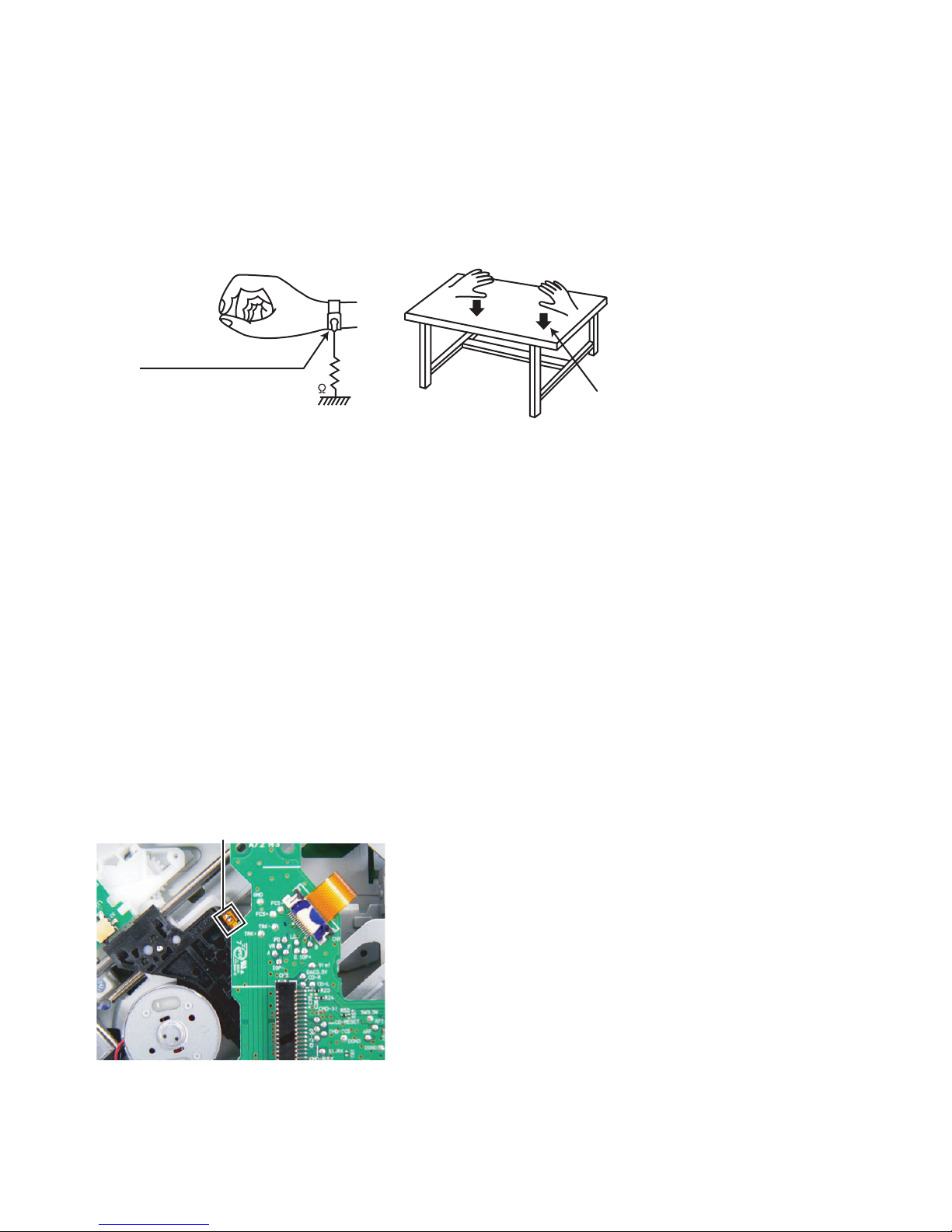
1.5 Preventing static electricity
Electrostatic discharge (ESD), which occurs when static electricity stored in the body, fabric, etc. is discharged, can destroy the laser
diode in the traverse unit (optical pickup). Take care to prevent this when performing repairs.
1.5.1 Grounding to prevent damage by static electricity
Static electricity in the work area can destroy the optical pickup (laser diode) in devices such as laser products.
Be careful to use proper grounding in the area where repairs are being performed.
(1) Ground the workbench
Ground the workbench by laying conductive material (such as a conductive sheet) or an iron plate over it before placing the
traverse unit (optical pickup) on it.
(2) Ground yourself
Use an anti-static wrist strap to release any static electricity built up in your body.
(caption)
Anti-static wrist strap
1M
Conductive material
(conductive sheet) or iron plate
(3) Handling the optical pickup
• In order to maintain quality during transport and before installation, both sides of the laser diode on the replacement optical
pickup are shorted. After replacement, return the shorted parts to their original condition.
(Refer to the text.)
• Do not use a tester to check the condition of the laser diode in the optical pickup. The tester's internal power source can easily
destroy the laser diode.
1.6 Handling the traverse unit (optical pickup)
(1) Do not subject the traverse unit (optical pickup) to strong shocks, as it is a sensitive, complex unit.
(2) Cut off the shorted part of the flexible cable using nippers, etc. after replacing the optical pickup. For specific details, refer to the
replacement procedure in the text. Remove the anti-static pin when replacing the traverse unit. Be careful not to take too long a
time when attaching it to the connector.
(3) Handle the flexible cable carefully as it may break when subjected to strong force.
(4) I t is not possible to adjust the semi-fixed resistor that adjusts the laser power. Do not turn it.
1.7 Attention when traverse unit is decomposed
*Please refer to "Disassembly method" in the text for the pickup unit.
• Apply solder to the short land sections before the card wire is disconnected from the connector on the servo board. (If the card wire
is disconnected without applying solder, the pickup may be destroyed by static electricity.)
• In the assembly, be sure to remove solder from the short land sections after connecting the card wire.
SOLDER
(No.WA063<Rev.003>)6/31
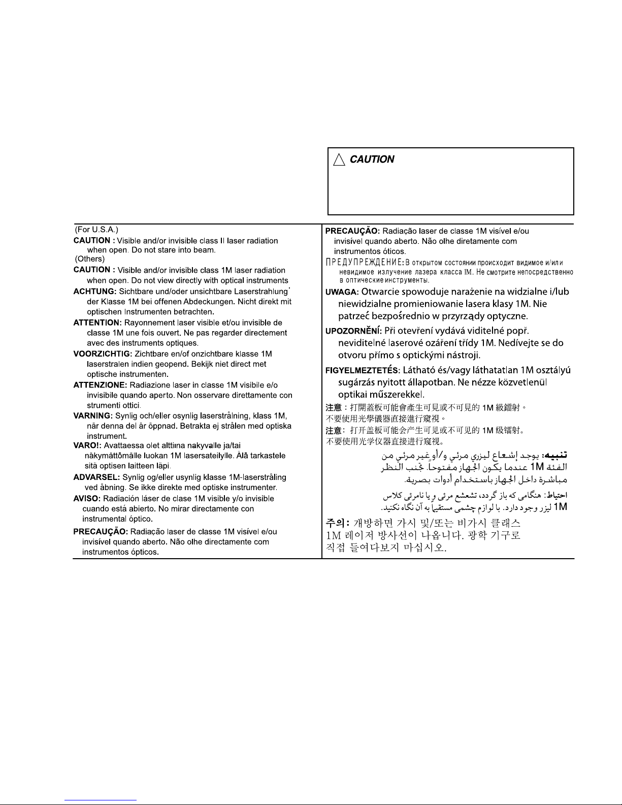
1.8 Important for laser products
1.CLASS 1 LASER PRODUCT
2.CAUTION :
(For U.S.A.) Visible and/or invisible class II laser radiation
when open. Do not stare into beam.
(Others) Visible and/or invisible class 1M laser radiation
when open. Do not view directly with optical instruments.
3.CAUTION : Visible and/or invisible laser radiation when
open and inter lock failed or defeated. Avoid direct
exposure to beam.
4.CAUTION : This laser product uses visible and/or invisible
laser radiation and is equipped with safety switches which
prevent emission of radiation when the drawer is open and
the safety interlocks have failed or are defeated. It is
dangerous to defeat the safety switches.
5.CAUTION : If safety switches malfunction, the laser is able
to function.
6.CAUTION : Use of controls, adjustments or performance of
procedures other than those specified here in may result in
hazardous radiation exposure.
!
Please use enough caution not to
see the beam directly or touch it
in case of an adjustment or operation
check.
(No.WA063<Rev.003>)7/31

SECTION 2
SPECIFIC SERVICE INSTRUCTIONS
2.1 COMPONENTS DESCRIPTION
2.1.1 ELECTRIC UNIT (X34-747x-xx)
Ref. No. Application / Function Operation / Condition / Compatibility
IC1 Power Supply IC Output 3.3V×2, 8V, 8.5V,10.5V, P-CON, P-ANT
IC21 1.2V AVR IC Power supply for Back up+1.2V(to u-com)
IC51 Switching Regulator Power supply for D+6V(to Power supply IC/USB5V AVR IC)
IC61 Switching Regulator Power supply for D+3.3V(to BT/CD/Panel Fil)
IC71 USB5V AVR IC Power supply for USB5V(to USB/2DIN Panel/SXM)
IC91 Hi-side SW Detection of USB Over Current
IC131 Muting logic IC Controls logic for muting
IC201 Power IC Amplifies the front L/R and the rear L/R to 50W maximum.
IC251 E-Vol Controls the source, volume, tone.
IC301 TUNER IC AM/FM radio receiver.
IC302 1.2V AVR IC Power supply for D+1.2V(to Tuner IC)
IC461 Level shift 3.3V to 5V(Communicates with SXM Tuner).
IC462 Level shift 5V to 3.3V(Communicates with SXM Tuner).
IC701 DAC3.3V AVR IC Power supply for DAC3.3V(to CD mechanism)
IC801 System u-com Controls FM/AM tuner, CD mechanism, Panel, volume and tone etc.
IC831 Flash ROM For memory of syscom software
IC841 Reset IC ''Lo'' when detection voltage goes below 2.8V
IC851 EEPROM For Log memory etc
IC861 iPod Authentication IC For Apple authentication.
Q131 SERGE Det. When Q131's base goes Hi, Serge voltage is detected.
Q132 BU.Det. ON when the base goes "Hi"during BU is applied.
Q133 ACC Det. ON when the base goes "Hi"during ACC is applied.
Q134 ILLUMI Det. When Q105's base goes Hi, Illumi is detected.
Q231,Q232 Pre-out mute SW When a base goes Hi, Pre-out is muted.
Q233,Q234 Pre-out mute SW When a base goes Hi, Pre-out is muted.
Q235,Q236 Pre-out mute SW When a base goes Hi, Pre-out is muted.
Q237 Mute driver for PRE OUT ON when the base goes "Lo".
Q402 A+5V AVR When Q402's base goes Hi, AVR outputs 5V
Q701,Q702 SW3.3V SW When Q702's base goes Hi, AVR outputs 3.3V
Q703,Q704 DAC3.3V SW When Q704's base goes Hi, AVR outputs 3.3V
Q861 iPod3.3V SW ON when the base goes "Lo".
Q901 Panel 3V SW ON when the base goes "Lo".
2.1.2 SWITCH UNIT (X16-743x-xx)
Ref. No. Application / Function Operation / Condition / Compatibility
IC601 LCD Driver Controls LCD and Key
IC602 Remote Control Sensor Output remote signal when IR of Remote controler
IC603 LED Driver LED is controlled. (D602,603,604,605,606,607,609,610,611,608)
IC604 LED Driver LED is controlled. (D608,615)
Q601 Variable LED drive BLUE of D602,603,604,605,606,607 are turned on when Q601 turn on.
Q602 Variable LED drive GREEN of D602,603,604,605,606,607 are turned on when Q602 turn on.
Q603 Variable LED drive RED of D602,603,604,605,606,607 are turned on when Q603 turn on.
(No.WA063<Rev.003>)8/31

Ref. No. Application / Function Operation / Condition / Compatibility
Q604 Variable LED drive BLUE of D609,610,611 are turned on when Q604 turn on.
Q605 Variable LED drive GREEN of D609,610,611 are turned on when Q605 turn on.
Q606 Variable LED drive RED of D609,610,611 are turned on when Q606 turn on.
Q608 Variable LED drive GREEN of D608 is turned on when Q608 turn on.
Q609 Variable LED drive RED of D608 is turned on when Q609 turn on.
Q610 Variable LED drive BLUE of D615 is turned on when Q610 turn on.
Q611 Variable LED drive GREEN of D615 is turned on when Q611 turn on.
Q612 Variable LED drive RED of D615 is turned on when Q612 turn on.
2.2 LCD DISPLAY INTERNAL SCHEMATIC DIAGRAM (X16-: ED1)
(No.WA063<Rev.003>)9/31
SECTION 3
DISASSEMBLY
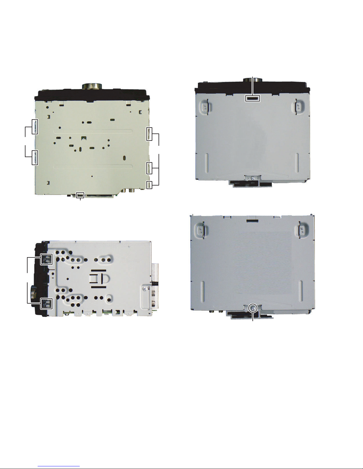
3.1 Main body
3.1.1 Removing the Bottom chassis (See Fig.1)
(1) Disengage the 6 hooks a engaging the Bottom chassis.
(2) Slide the Bottom chassis backward to remove it.
a
a
Fig.1
3.1.2 Removing the Front chassis (See Fig.2, 3)
(1) Disengage the 4 hooks b engaging both sides of the Front
chassis.
(See Fig.
2)
(2) Disengage the 1 hook c engaging the Front chassis.
Fig.
3)
(See
c
a
Fig.3
3.1.3 Removing the Electric unit (See Fig.4, 5, 6, 7 and 8)
Remove the 1 screw A attaching the Top chassis. (See Fig.
(1)
4)
b
Fig.2
A
Fig.4
(No.WA063<Rev.003>)10/31
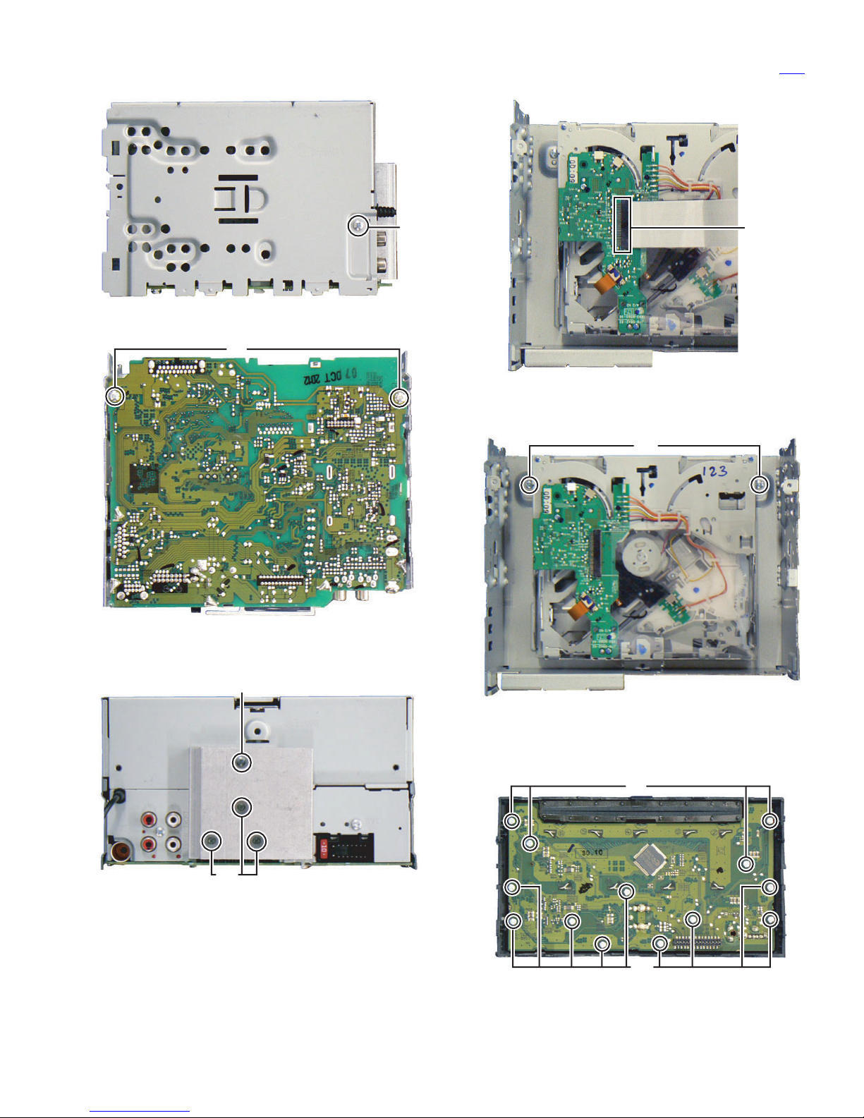
(2) Remove the 2 screw B attaching both sides of the
. (See Fig.5)
chassis
Top
(5) Disconnect the FFC wire connected to connector CN2
the CD mechanism. (See Fig.8)
of
B
Fig.5
(3) Remove the 2 screws C attaching the Electric unit. (See Fig.6)
C
Fig.6
(4) Remove the 1 screw D and 3 screws E attaching the Heat
sink. (See Fig.7)
CN2
Fig.8
3.1.4 Removing the CD mechanism (See Fig.9)
(1) Remove the 2 screws F attaching the CD mechanism.
F
D
E
Fig.7
Fig.9
3.1.5 Removing the Switch unit (See Fig.10)
(1) Remove the Volume knob.
(2) Remove the 13 screws G attaching the Switch unit.
G
G
Fig.10
(No.WA063<Rev.003>)11/31
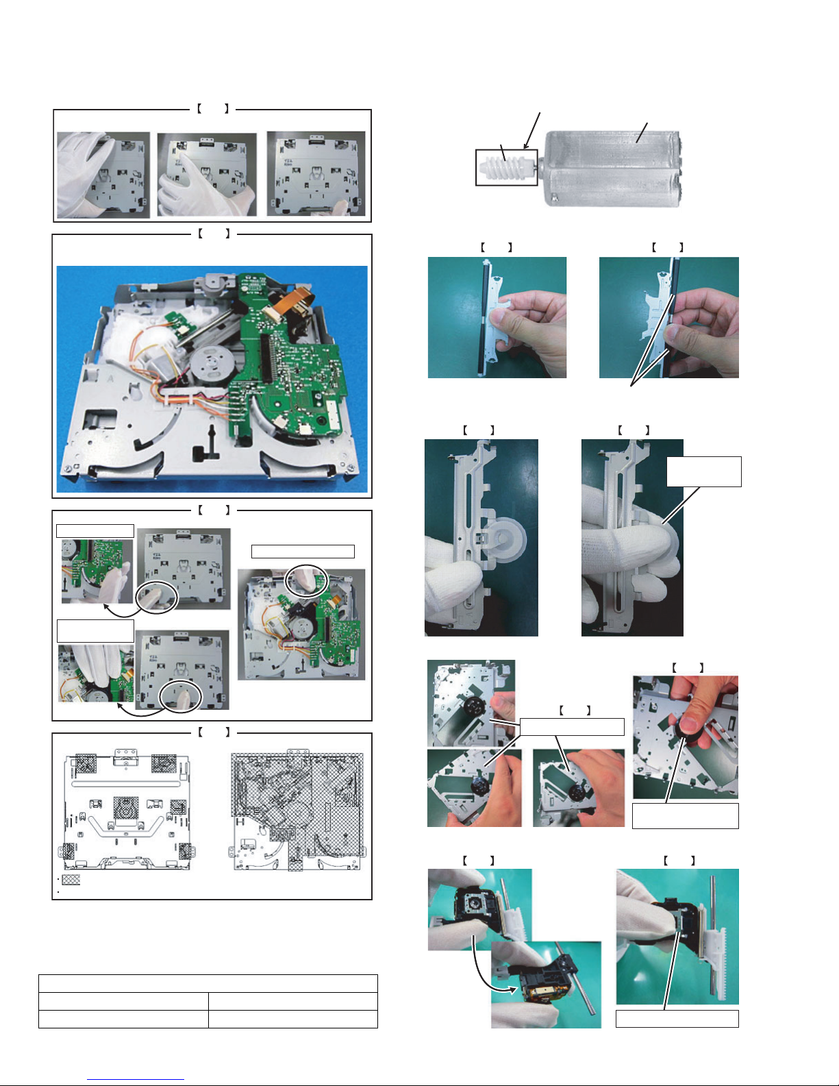
3.2 CD mechanism
• NOTICE FOR HANDRIG OF MECHANISM ASSY
OK
Handle CHASSIS part.
• NOTICE FOR HANDRIG OF FEED MOTR ASSY
CAUTION: For mounting FEEDMOTOR ASSY, DON'T bump this part.
Because handling may cause this part easily deformed.
FEED MOTOR
WORM 1
NG
Do not stay MECHANISM ASSY in upside-down condition
for 1 hour and more.
NG
Do not touch P.C.B..
Do not touch DAMPER.
• NOTICE FOR HANDRIG OF ROLLER LEVER ASSY
OK
Do not handle roller part.
NG
• NOTICE FOR CLAMPER ASSY OF PICK UP ASSY
OK NG
Do not handle
the clamper part.
Do not touch
PICK UP ASSY.
NG
TOP SIDE BOTTOM SIDE
DO NOT TOUCH AREA
DO NOT TOUCH HOLES, MOTOR, DAMPER, PCB, FFC, OPU AND WIRE.
• THESE PARTS NEED CAUTION OF HANDLING
CAUTION:
Don't touch the following parts in particular by the hand which
touched grease. (It becomes a cause of traction problem)
CAUTION PARTS
HC TURN TABLE TRIGGER ARM
ROLLER DISC GUIDE
• NOTICE FOR HANDRIG OF MD CHASSIS ASSY
NG
OK
Handle CHASSIS part.
Do not handle the
turn table part.
• NOTICE FOR HANDRIG OF PICK UP ASSY
OK NG
Do not handle the lens part.
(No.WA063<Rev.003>)12/31
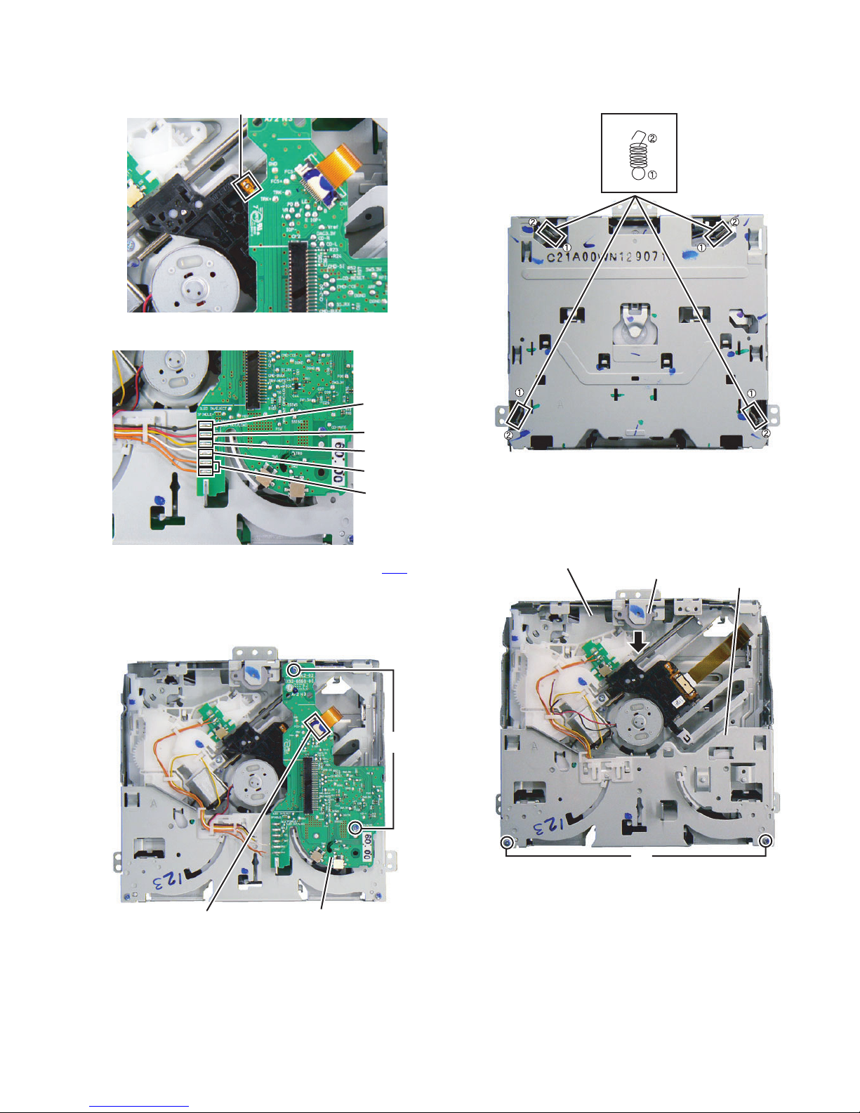
3.2.1 Removing the CD Player unit (See Fig.1 to 3)
(1) Solder the short land on the Pickup. (See Fig.1)
SOLDER
Fig.1
(2) Remove the 6 wires from the CD Player unit. (See Fig.2)
Black
Red
Yellow
Orange
Fig.2
(3) Disconnect the FPC wire from the connector CN1 (CD
Player unit). (See Fig.3)
(4) Remove the 2 screws A attaching the CD Player unit.
(See Fig.3)
(5) Remove the CD Player unit. (See Fig.3)
White
Orange
3.2.2 Removing the Traverse mechanism (See Fig.4, 5)
(1) Remove the 4 springs from the traverse mechanism.
(See Fig.4)
Spring
Fig.4
(2) Remove the 2 screws B attaching the Lower chassis.
(See Fig.5)
(3) Remove the Damper in the direction of the arrow.
(See Fig.5)
(4) Remove the Traverse mechanism. (See Fig.5)
Traverse mechanism
Damper
Lower chassis
CN1
CD Player unit
Fig.3
A
B
Fig.5
(No.WA063<Rev.003>)13/31
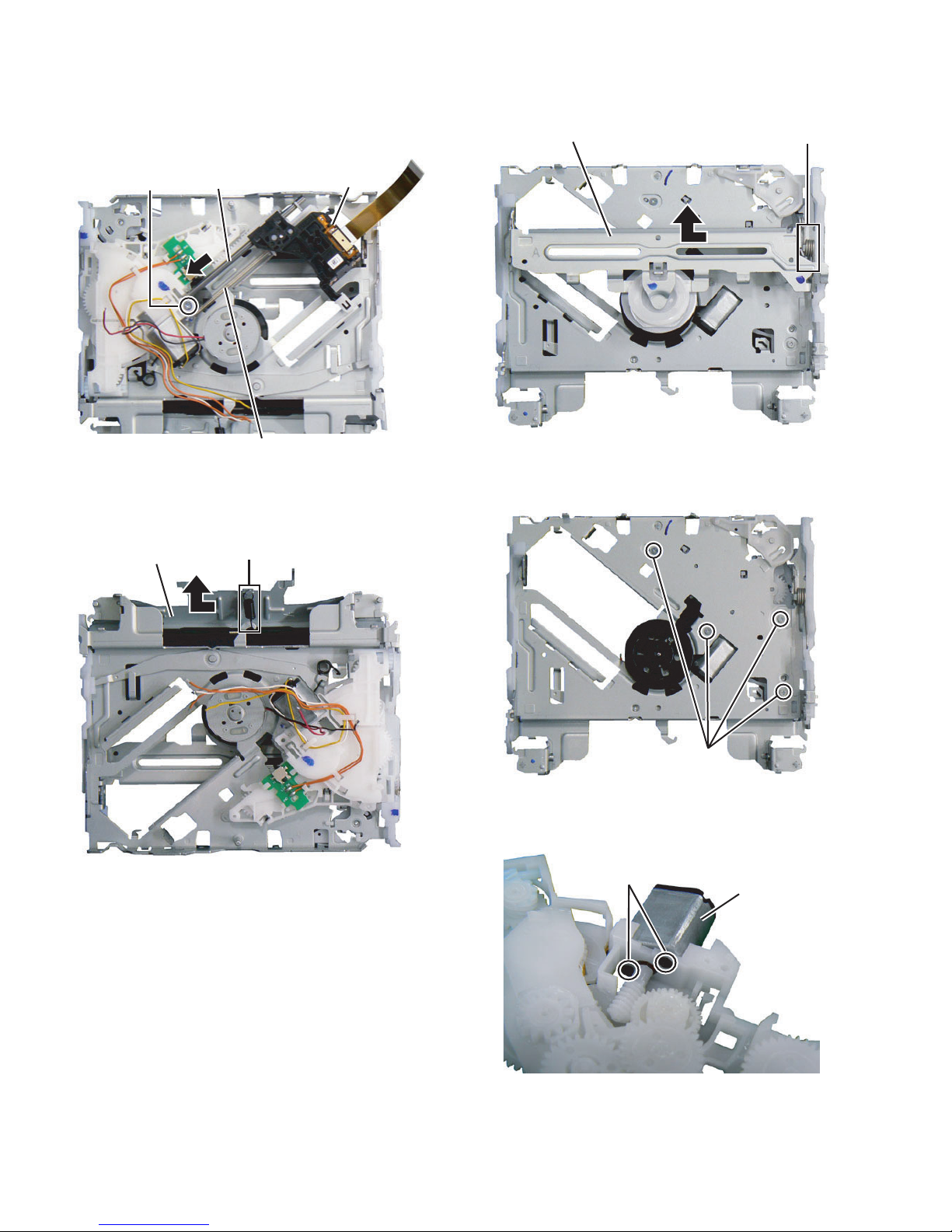
3.2.3 Removing the Pickup assy (See Fig.6)
(1) Remove the 1 screw C.
(2) Remove the Main shaft in the direction of the arrow.
(3) Remove the Spring.
(4) Remove the Pickup assy.
3.2.5 Removing the Clamp arm assy (See Fig.8)
(1) Remove the Spring.
(2) Remove the Clamp arm assy in the direction of the arrow.
Clamp arm assy
Spring
Main shaft
C
Spring
Fig.6
3.2.4 Removing the Roller lever assy (See Fig.7)
(1) Remove the Spring.
(2) Remove the Roller lever assy in the direction of the arrow.
Roller lever assy
Spring
Pickup assy
Fig.8
3.2.6 Removing the Feed motor (See Fig.9, 10)
(1) Remove the 4 screws D attaching the Feed motor assy.
(See Fig.9)
Fig.7
D
Fig.9
(2) Remove the 2 screws E attaching the Feed motor.
(See Fig.10)
(3) Remove the Feed motor. (See Fig.10)
E
Feed motor
Fig.10
(No.WA063<Rev.003>)14/31
SECTION 4
ADJUSTMENT
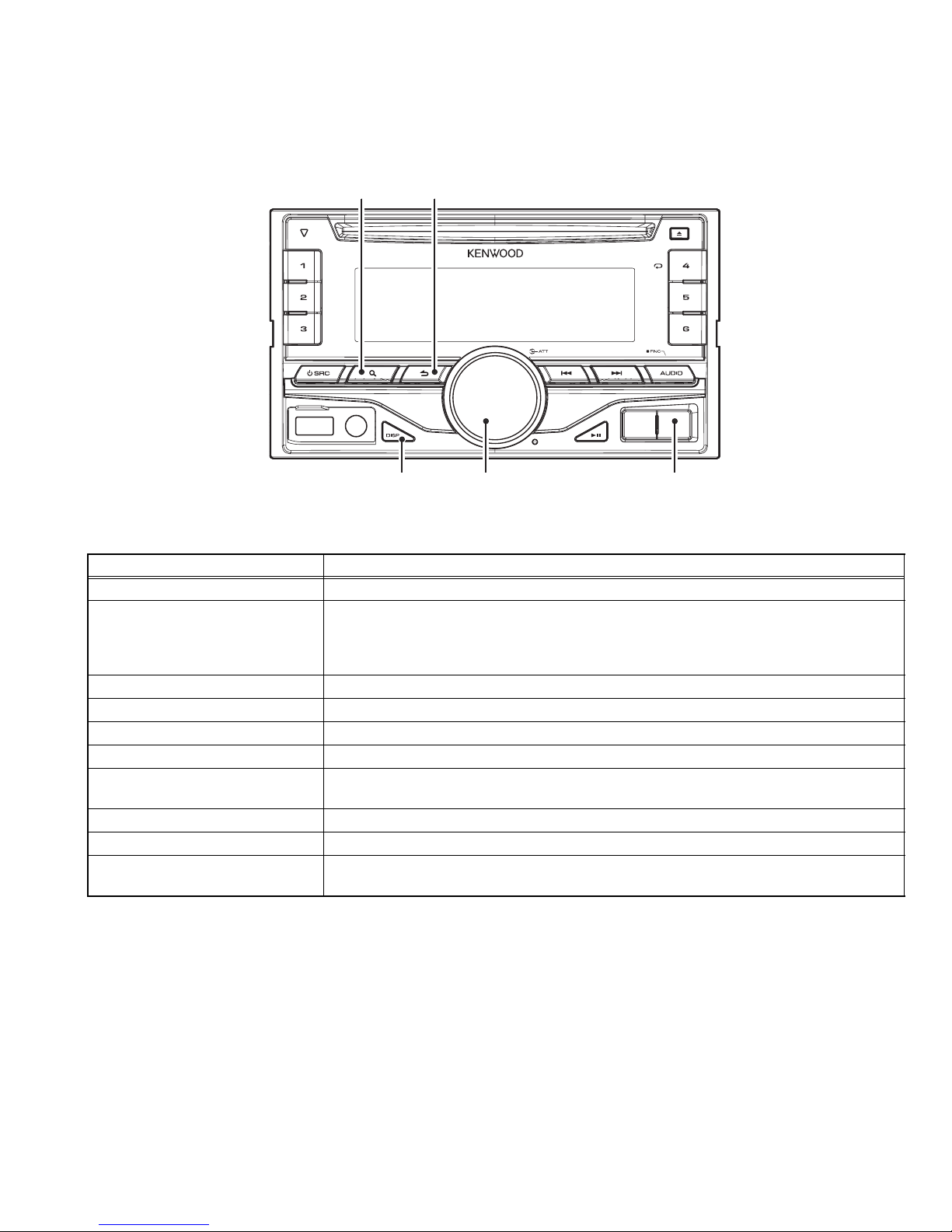
4.1 TEST MODE
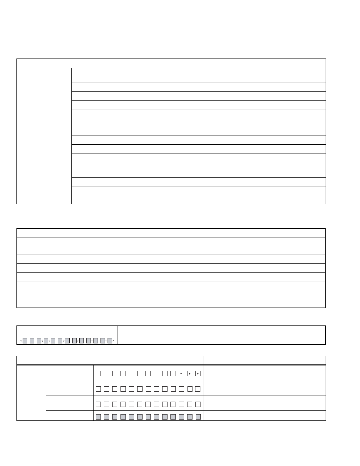
4.1.1 Panel
SEARCH RETURN
ACCENTVOLDISP
A symbol "" in the key column indicates that the key should be pressed and hold for 1 second or longer.
4.1.2 How to enter each Test Mode
Test Mode name Operation
Production Test Mode Press and hold [1] key and [3] key and reset.
Service Test Mode In the STANDBY source, while pressing and holding [SEARCH] key, press [AUDIO] key for 7
seconds.
(Starting to press [SEARCH] key and [AUDIO] key at the same time can not be entered into
the mode)
Service Information Clear Mode Press and hold [2] key and [5] key and reset.
DC Error Information Mode Press and hold [3] key and [6] key and reset.
Forced update mode Press and hold [1] key and [SEARCH] key and reset.
Version display mode In the STANDBY source, while pressing and holding [RETURN] key, press [DISP] key.
FM/AM channel space switching
mode
Forced Power ON mode Press and hold [ENTER] key and [4] key and reset.
Security Code Force Delete mode While pressing and holding [] key, press [SEARCH] key for 3 seconds.
Diagnostic Data Mode In the SXM source, press and hold [RETURN] key and [ACCENT] key for 7 seconds.
*Transition to Test Mode shall be available during DC Error detection.
However, operation by the remote controller cannot be done since the transition to each test mode by using a remote controller can
be done only from a normal display.
Also, since "PROTECT" is displayed forcibly upon detection of 4 times or more condenser leaks, transition to each test mode is not
available.
*Transition to DC Error Information Mode shall be available during DC Error detection.
4.1.3 How to release each Test Mode
• Reset
• Momentary voltage drop
• ACC OFF
• POWER OFF
• Optional key operation (version display only)
• Short ACC OFF/ON
While Power OFF, pressing and holding [1] key and [5] key to Power ON.
(It is necessary to connect tuner box sold separately)
(No.WA063<Rev.003>)15/31
4.2 Production Test Mode
Press and hold [1] key and [3] key and reset.
4.2.1 Default condition when the mode is started
It shall be same as normal RST start in other settings than the following.
Details
Difference in action Period to prohibit TEL/LINE MUTE immediately after activation
1 second
(normally 10seconds)
CD Mecha Initialize Action Prohibited
Write-in to E2PROM when detecting a DC error Prohibited
Demo Mode ON/OFF Setting Menu Prohibited
Power supply during ACC OFF (Back Up On) MUTE terminal turns OFF after 2 seconds
BEEP sound Beep with short-pressing in any functions
Various setting value Volume 33 (-10dB)
BASS BOOST/LOUDNESS OFF
EQ NATURAL
Fader/Balance Center
Volume Offset -6: for only SXM source
0: for the other sources
DEMO Mode Setting OFF
AUX Setting (Built-In-Aux) ON
BT speaker Setting ALL
4.2.2 Mode structure
Some Test Modes change according to the current source.
The following table shows the current source in Set and the related test mode status.
Model source Test mode
POWER OFF -
Standby STANDBY Test mode
TUNER TUNER Test mode
SXM SXM Test Mode
CD CD Test mode
BT BT Test mode
USB USB Test mode
AUX -
4.2.3 Mode content
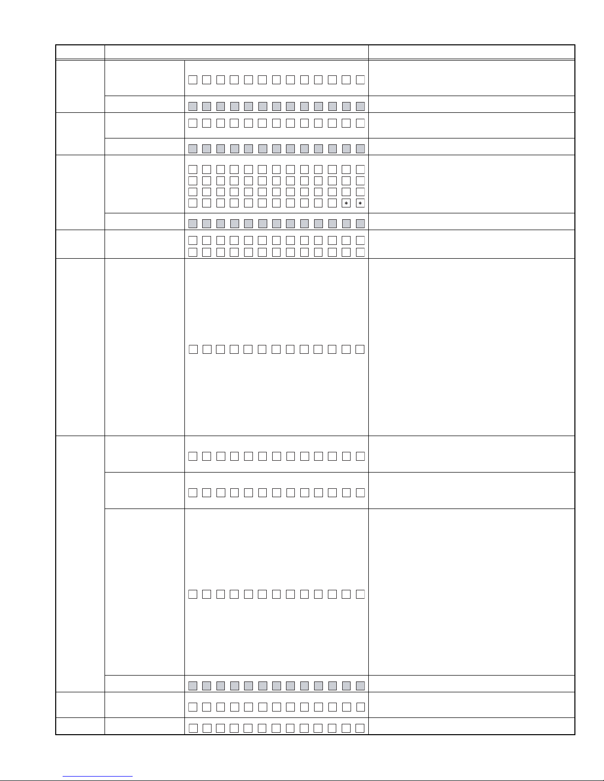
Syscom shall display the following information after entering this mode. The operation shown below shall be workable.
Display content Details
All lights ON
4.2.4 STANDBY Test Mode Specification
Operation
1 (Toggle)
Syscom version
display
BT Module version
display
Media control part
version display
All lights ON
Display content Details
S01SY -
BT XX XXS
A:DEMI xxxx
xxx: Version (Micom)
BT Module version display
Media control part version display
All lights ON (Switch with other display)
(No.WA063<Rev.003>)16/31
Operation
Serial No. display
2 (Toggle)
All lights ON
Disc Eject number
3 (Toggle)
of times display
All lights ON
Information display
iPod verification IC
4 (Toggle)
mount status
display
All lights ON/TEST
5 (Toggle) Preout switch
6 (Toggle)
DISP&ILLUMI
color switching
DOP information
display
DOP information
display (steering
remote control)
SEARCH
(Toggle)
DOP information
display (steering
remote control)
All lights ON
Audio data Initialize
Display content Details
Serial No. display (8-digit)
SN xxxxxxxx
*Displays ASCII
"********" is displayed if there is no registration
All lights ON (Switch with other display)
JECNT x xxxx
:
Display Disc Eject number of times.
MAX 65535 (times)
All lights ON (Switch with other display)
Piod :
Pio OK
d:
Piod :
Piod :
iPod verification IC mount status display
Blank: Verifying
OK: Verification IC mounted
NG
NG: Verification IC not mounted
**: Non-iPod support model
All lights ON (Switch with other display)
SWP R R REEA
SWP R S –EUBW
Switch Preout with toggle
Initial value: Rear
All lights on by setting the RGB setting values indicated below (switch with toggle).
Default value is white.
R=9; G=9; B=9 (white) → R=9; G=0; B=0 (red) →
R=0; G=0; B=9 (blue) → R=0; G=9; B=0 (green) →
R=9; G=9; B=9 (white)...
Since the [ACCENT] key for the model with BT is assigned to 2 colors (green and red), switch with toggle
according to the following order. (Lights off when the
LED is white, red when it's red, lights off when it's
blue, and green when it's green)
Default value: all lights off → red → all lights off →
green → all lights off
*Since the red and green LED for the [ACCENT] key
can not light on at once due to the circuit, these light
up alternately.
DOP information display
PDO xxx:
*Displays the DOP type in 3-digit value.
*"----" is displayed for the commercial model.
DOP steering remote control information display
P-STDO R x xx:
*Displays the remote control type in 3-digit value.
*"----" is displayed for the commercial model.
DOP steering remote control information display
Voltage within the range of the remote control
threshold: OK
Other than above: NG
• 1xx: determination result of ch1
• 2xx: determination result of ch2
*OK/NG is determined when the steering remote
L1VDOP - x x2xx
control jig is connected, and when the toggle operation is performed.
*Threshold range of the "OK" determination result is
the following:
PIN No.52 STG-REMO1 2.313V to 2.513V (718 to
780)
PIN No.53 STG-REMO2 0.855V to 1.055V (265 to
328)
When key is pressed, all lights ON/OFF with toggle
AUD I O I INT
AUDIO setting value is re-set to default value of the
test mode.
When key is pressed, all lights ON/OFF with toggle
(No.WA063<Rev.003>)17/31

Operation
SOURCE
transition
RETURN
RETURN
DISP
Mode release
Display content Details
Performs the SOURCE transition.
After the SOURCE transition, normal display for
each mode resumes.
When key is pressed, all lights ON/OFF with toggle
When key is pressed, all lights ON/OFF with toggle
When key is pressed, all lights ON/OFF with toggle
4.2.5 Tuner Test Mode Specification
The following display shall be indicated according to the TUNER status.
Status Display content Details
TUNER IC
Communication
Error
RDS specific data
reception
Normal operations
other than above
TUN CON NG
RDS T TES
FM# A A97.9
Communication to TUNER IC not available (indicated unless the
mode is in Clock Display Mode).
Press and hold the [RETURN] key after the display is switched
to "TUN CON OK" to resume normal operations.
PS: P-CON is forcibly set to OFF when the RDS test is received.
P-CON is recovered by the Power OFF/ON switch.
Frequency is displayed during normal operations other than
above.
4.2.5.1 Operations
Operation
Display content Details
S meter value
xx: Current S meter value
Judgement result
OK: Within S meter voltage spec (P-CON OFF)
SEARCH
S meter voltage
judgement display
MS– T x:xORK
MS– T x:xNRG
NG: Out of S meter voltage spec (P-CON ON)
Display TUNER IC version
ACCENT TUNER IC display
EHLIO xyyzzx
xx: hexadecimal indication of IDENT0
yy: hexadecimal indication of IDENT1
zz: hexadecimal indication of IDENT2
SEARCH
DISP
BAND switch
operation
PIN diode switch
(OK)
PIN diode switch
(NG)
PIN diode switch
(Not supported)
MF1–3 7.99AA
IPN–S OK
IPN–S NG
IPN–S NA
Execute Band Switch as shown in the following table
every time [SEARCH] key is pressed in each type.
Perform the PIN diode check when the Analog Tuner FM is selected, and display the result.
** indicates the value of S-Meter.
OK: check completed
NG: check not completed
NA: Tuner is not supported
RETURN Return transition Return to the Tuner display in the Tuner test mode.
4.2.5.2 BAND switch list
Type BAND1 BAND2 BAND3 BAND4 BAND5 BAND6 Details
K (1)FM1 (2)FM2 (3)FM3 (4)AM - - (1)→(4)
E (1)FM1 (2)FM2 (3)FM3 (4)MW/LW - - (1)→(4)
M/H (1)FM1 (2)FM2 (3)FM3 (4)MW (5)SW1 (6)SW2 (1)→(4)→(5)
(No.WA063<Rev.003>)18/31
4.2.6 Sirius XM Test Mode Specification
Perform a communication test with the Sirius XM Tuner SXV100. If the test result is OK, 1kHz signal is output from the internal tone
generator of the SXV100.
Without preconditions, in the test mode, start in a state of receiving 0ch.
Press the [RETURN] key to switch the signals in the order of L/R → L → R → OFF. (Default setting is L/R.)
• Volume setting in the Sirius XM source
The level of the internal tone generator output cannot be adjusted. If the Sirius XM source is selected in the test mode, set the VOL
offset to "-6".
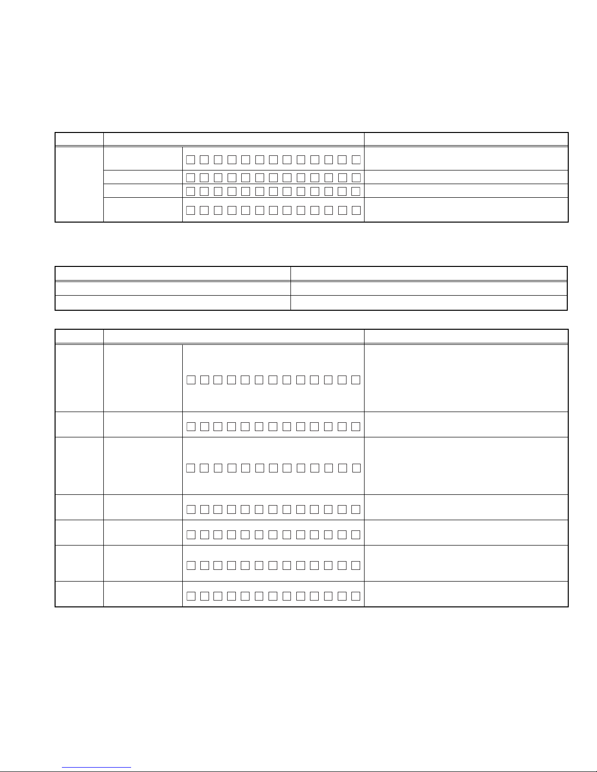
Operation Display content Details
RETURN
Left & Right
Channel
Left Channel Output 1kHz signal for Left channel.
Right Channel Output 1kHz signal for Right channel.
Off
xxxxxxxx
LEFT
RIGHT
OF F
xxxxxxxx: 8 characters Radio ID.
Output 1kHz signal for Left/ Right channel.
No Tone generator output (same as normal operation).
Follow the specifications of the normal display if any channel other than 0ch is received.
4.2.7 CD Test Mode Specification
It shall be the same as normal RST start in other than the below setting.
Content Details
Playback track from top No.9
Default for Display mode Play time
4.2.7.1 Operations in CDDA playback
Operation
Special track up
Special track down
1 (Toggle)
3
4
5
6
File type display
Special jump
operation
Special jump
operation
Special jump
operation
Special jump
operation
Display content Details
Pressed Track up depend on different cases.
Case 1: Track>8
No.9 → No.15 → No.10 → No.22 → No.12 → No.13
→ No.14 → No.9
Case 2: Track< 8
No.1 → No.2 → No.3 → Until Last Track
One-by-one Track down by sequence follow Track
No.
CDDA/ MP3/ WMA/ AAC Judgement Information
CD: CDDA track playback
xxx
MP3: MP3 file playback
WMA: WMA file playback
AAC: AAC file playback
Jump to No.28
(Scratch 0.7mm for MUSIC line vibration test)
Jump to No.14
(Damaged disc TCD-731RA Tr14)
Jump to No.15
Set Volume value at 27 (for error operation FCT
check of 20Hz 0dB DC protection)
Jump to No.9 if the other than track No.9 is playing.
Jump to No.22 if the track No.9 is playing.
(No.WA063<Rev.003>)19/31

4.2.8 BT Test Mode Specification
Initial condition of the BT MODE (BT source) will display as following.
Status Display content Details
BT MODE BT MODE display
BT OMDE
BT module error display
BT ERR RO
P-CON is off at the time of an error.
(Error display appears and P-CON is turned OFF when switched
to the BT source)
P-CON recovers with Power OFF/ON.
* "BT(HF1)" dot lights on when the BT module is started, since it takes a while to start the BT module.
"BT(HF1)" dot is blinking during startup of the BT module, and turned off when an error occurs.
Lighting display can be checked in sources except for the STANDBY source.
4.2.8.1 Operations during BT MODE
Operation
Display content Details
ACCENT Clear the BT MODE and transition to the last source.
Clear the BT
related memory
information *1
IN TIIAIZEL
BT I N I O:KT
BT I N I N:GT
Press and hold this key for 2 seconds. The character
string as shown in the left cell is displayed while the
BT related memory is being initialized.
This is to initialize the BT related memory to its factory default condition. When the initialization is successfully completed,"...OK"(upper) is displayed, and
when the initialization is abnormally completed,
"...NG"(lower) is displayed.
SEARCH BT device search Perform a BT device search for 15 seconds after
(The display blinks)
S
ERACHI GN
pressing the button.
Exit the SEARCHING standby when 1 device is
found.
Name of the found device is displayed if a device is
found during the search.
XX XXXXXXXXXXX
Pressing a key other than [SEARCH] after the
search will enter to the mode that is assigned to the
key.
If no device is found upon completion of the search;
UN NKOWN
only in this case, perform a search again by pressing
the [VOL] key.
Upon completion of the search, press the [SEARCH]
key to clear the mode.
VOL Internal loop back
ON *2
• Press and hold this key to set the Volume to 15
and turn ON the internal loop back function.
While doing so, the internal loop back display on
the left appears after the Volume change display.
• INT LOOP R: internal loop back display of a REAR
(external) mic. Set the value of MIC GAIN to 0.
• Default value for models with the mic setting is
INT LO P RO
FRONT.
• For models without the mic setting, mic position of
each model is displayed.
• While in the ON state, no change in display other
than [F] or [R].
• Set the BT speaker output to ALL.
To exit the loop back, clear the mode by pressing the
[VOL] key.
(No.WA063<Rev.003>)20/31
 Loading...