

Kenwood DMCJ-7-R Service Manual

General
Power source DC ........................
.............
........................
.......................
.....
...........
3.6 V (rechargeable lithium-ion
battery NB-L10A x 1)
DC 5 V (AC adaptor)
AC 230 V, 50 Hz
DC 3 V Separately available battery case
(commercially available, "AA"
size, alkaline battery x 2)
DC 4.0 V : Separately available car
adaptor, DC-C70
(for cars with a 12-24 V DC
negative earth electrical system)
Power consumption 7 W (AC adaptor)
Output power RMS; 20 mW (10 mW + 10 mW)
(0.2 % T.H.D.)
Charging time Approx. 3.0 hours
(When using the AC adaptor included
with the unit)
Battery life
Note:
The battery case is only sold in certain areas. For more details,
please ask your dealer.
The continuous recording time is for analogue input when the
volume level is set to "VOL 0".
The continuous play time shows the value when the volume level is
set to "VOL 15".
The above values are the standard values when the unit is charged
and used at an ambient temperature of 20
o
C.
The operating time when using alkaline batteries may be different,
depending on the type and manufacturer of the batteries, and on
the operating temperature.
Input sensitivity
Output level
Dimensions Width: 87.0 mm (3-7/16")
Height: 29.4 mm (1-3/16")
Depth: 81.5 mm (3-7/32")
Weight 219 g (0.49 lbs.) with rechargeable
battery
Input socket Line/optical digital, microphone
(powered by the main unit)
Output socket Headphones (impedance: 32
ohms)/remote control unit
MiniDisc Recorder
Type Portable MiniDisc recorder
Signal readout Non-contact, 3-beam semi-coductor
laser pick-up
Audio channels Stereo 2 channels/monaural (long-
play mode) 1 channel
Frequency response 20 - 20,000 Hz (± 3 dB)
Rotation speed Approx 400 - 900 rpm
Error correction ACIRC (Advanced Cross Interleave
Reed-Solomon Code)
Coding ATRAC (Adaptive Transform
Acoustic Coding), 24-bit computed type
Recording method Magnetic modulation overwrite method
Sampling frequency 44.1 kHz (32 kHz and 48 kHz
signals are converted to 44.1 kHz,
and then recorded.)
Wow and flutter Unmeasurable (less than ±0.001% W.peek)
Continuous recording:
Approx. 4.5 hours
Continuous recording:
Approx. 4 hours
Continuous recording:
Approx. 8.5 hours
Continuous play:
Approx. 6.5 hours
Continuous play:
Approx. 8 hours
Continuous play:
Approx. 14.5 hours
Headphones — 10 mW + 32 ohms
10 mW
LINE 300mV (-12dB) — 50 k ohms
Maximum
output level
Specified output
Recording level Reference input level Input impedance
MI C H 0.25 mV 10 k ohms
MIC L 2.5 mV 10 k ohms
LINE 100 mV 20 k ohms
Load
impedance
When using two,
commercially available,
high capacity, "AA" size,
alkaline batteries (in the
separately available battery
case)
When using the rechargeable battery NB-L10A (fully
charged) included with the
unit
When using two, commercially
available, high capacity, "AA"
size batteries with the
rechargeable battery (fully
charged)
....................
............
............
...............
....................
....................
.......................
..........................
...........................
.....................
......................
.......................................
...................................
...................................
DIGITAL EDIT & RECORDING
RECORDING
REC LEVEL
/CURSOR
CHARACTER
AUTO MARK
SYNC/F.PLAY
VOLUME/NAME
PORTABLE MD RECORDER DMC-J7R
BASS/DELETE MODE/INSERT
OPEN
DISP
EDIT
OFF
ENTER
E
J
E
C
T
PORTABLE MD RECORDER
DMC-J7R
SERVICE MANUAL
Transparency cover *
(B10-)
Knob
(K27-2272-08)
Front cabinet
(A02-2808-08)
MD cover
(F07-1638-08)
© 1998-6/B51-5441-00 (K/K) 3163
Upper case assy
(A02-2814-08) : S
(A02-2862-08) : B
Knob base
(A02-2816-08)
Knob
(K29-2270-08)
In compliance with Federal Regulations, following are reproductions of labels on, or inside the product relating to laser product
safety.
SPECIFICATIONS
KENWOOD-Crop. certifies this equipment conforms to DHHS
Regulations No. 21 DFR 1040. 10, Chapter 1, Subchapter J.
DANGER : Laser radiation when open and interlock defeated.
AVOID DIRECT EXPOSURE TO BEAM
* Refer to parts list on page 26. S: Silver, B: Blue
Bottom cabinet *
(A02-)
DMC-J7R
How to reset
When this product is subjected to strong
external interference (mechanical shock,
excessive static electricity, abnormal supply voltage due to lightning, etc.) or if it is
operated incorrectly, it may malfunction. If
such a problem occurs, do the following:
1. Unplug the AC adaptor from the AC
socket.
2. Remove the battery.
3. Leave the unit completely unpowered
for approximately 30 seconds.
4. Plug the AC adaptor back into the AC
socket and retry the operation.
If strange sounds, smell or smoke come
out of the unit or an object is dropped into
the unit, remove the AC adaptor from the
AC socket immediately and contact an authorized KENWOOD service centre.
CONTENTS / ACCESSORIES / CAUTIONS
Contents
SPECIFICATIONS.........................................Top cover
CONTENTS / ACCESSORIES / CAUTIONS...............2
CONTROLS.................................................................3
DISASSEMBLY FOR REPAIR.....................................4
BLOCK DIAGRAM.......................................................6
CIRCUIT DESCRIPTION.............................................7
TROUBLE SHOOTING................................................8
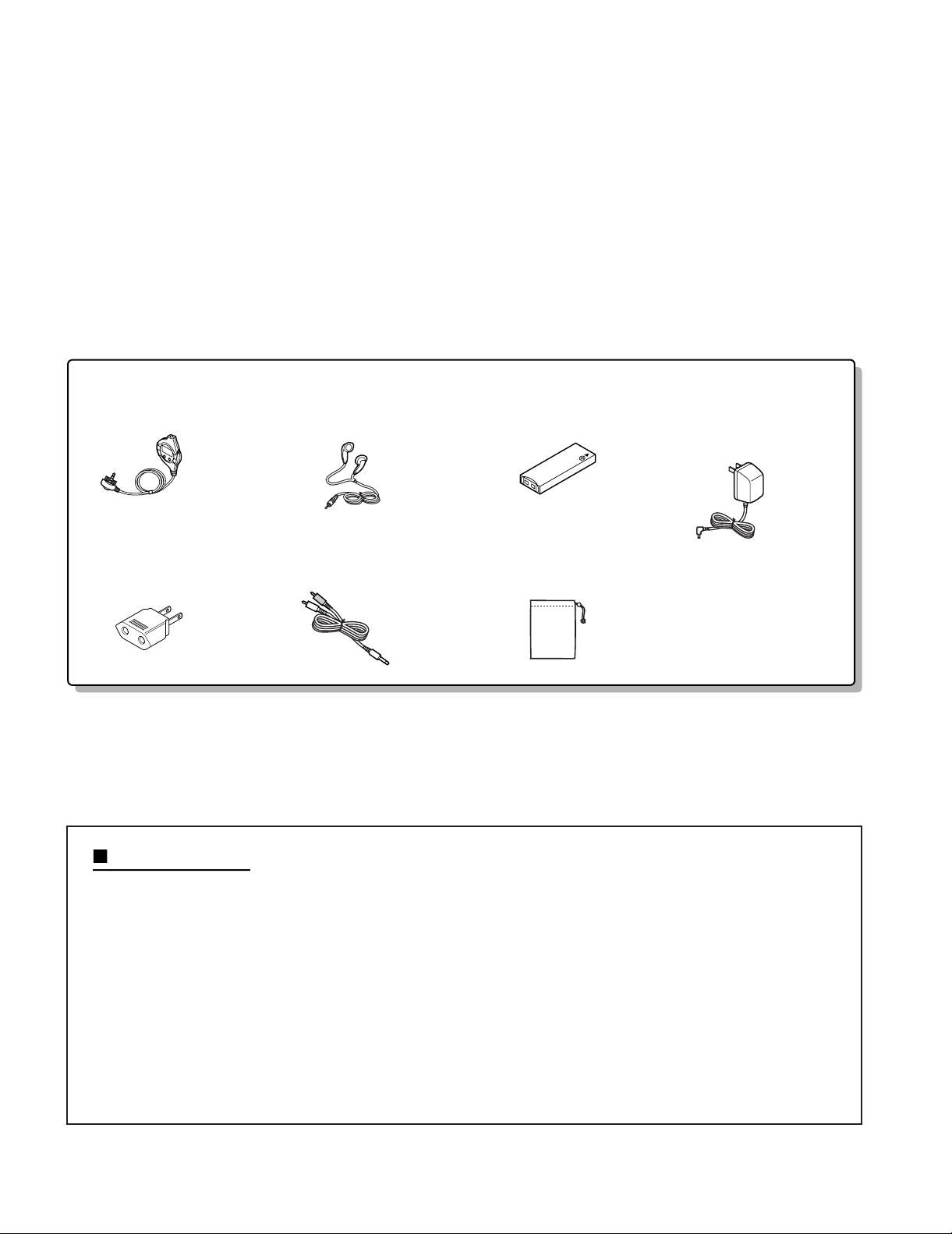
Accessories
NOTE ON SCHEMATIC DIAGRAM...........................14
PARTS DESCRIPTIONS...........................................15
WAVEFORMS OF MD CIRCUIT ...............................16
PC BOARD ................................................................17
SCHEMATIC DIAGRAM............................................21
EXPLODED VIEW .....................................................24
PARTS LIST...............................................................26
Remote control (1)
(A70-1210-08)
AC plug adapter (1)
(E03-0115-05) : M type
Cautions
Stereo headphone (1)
(W01-0941-05) : K,P type
(W01-0948-05) : T,E,E1,M type
Connecting cord (1)
(E30-2836-08)
Rechargeable battery (1)
(W03-5946-08): NB-L10A
Carrying case (1)
(W01-0955-08)
AC adapter (1)
(W08-0669-08) : M type
(W08-0672-08) : E,E1 type
(W08-0673-08) : T type
(W08-0674-08) : K,P type
2
Error messages Meaning Remedy
BATT EMPTY
The battery run down. Charge the rechargeable battery or
replace the alkaline batteries (or use
the AC adaptor for power).
BLANK DISC
Nothing is recorded. Replace the disc with a recorded
disc.
Can't COPY
No copy can be made because of
the SCMS copyright system.
Record using the analogue cable.
Can't EDIT
A track cannot be edited. Change the stop position of the
track and then try editing it.
Can't REC
Recording cannot be performed
correctly due to vibration or shock
in the unit.
Re-record or replace it with another
recordable disc.
Can't WRITE Editing is impossible. Check the number of tracks.
DEFECT
The disc is scratched. If the sound you hear is not right,
try recording again.
Replace the disc with another
recordable disc.
Din UNLOCK Poor connection of the digital cable. Connect the digital cable securely.
DISC ERROR The disc is damaged. Reload the disc or replace it.
DISC FULL
The disc is out of recording space. Replace it with another recordable
disc.
HOLD
The unit is in the safety mode. Return the HOLD switch to its
original position.
LOCKED
LOCK ERROR
The EJECT lever was moved
during recording or editing.
Turn off the power and remove the
MiniDisc.
NO DISC A disc has not been loaded. Load a disc.
PB DISC
PROTECTED
The disc is write protected.
You tried to record on a playbackonly disc.
Move the write protection knob
back to its original position.
Replace it with a recordable disc.
POWER ?
Improper power is being supplied. Use one of the specified power
sources.
SORRY
Since a track number is currently
being located or written to, the unit
cannot accept your command.
Wait for a while and try the
operation again.
SYSTEM ERR
You have come to the conclusion
that the unit is out of order.
To have it repaired, go to the
distributor where you purchased the
unit.
TEMP OVER
The temperature is too high. Turn off the power, and wait for a
while.
TOC ERROR
A large portion of the disc has been
damaged.
Replace it with another recorded
disc.
TOC FULL
There is no space left for recording
character information (track names,
disc names, etc.).
Replace it with another recordable
disc.
Tr. Protect
The track has been protected from
being erased.
Edit the track with the device on
which it was recorded.
U TOC ERROR
A large portion of the disc has been
damaged.
There is an error in the recorded
signal.
Replace it with another recorded
disc.
Erase all of the signal errors, and
then try recording again.
? DISC
A disc which contains data other
than music was played.
There is an error in the signal from
the disc.
A disc which contains non-music
data cannot be played.
Replace it with another recorded
disc.
ERROR MESSAGES
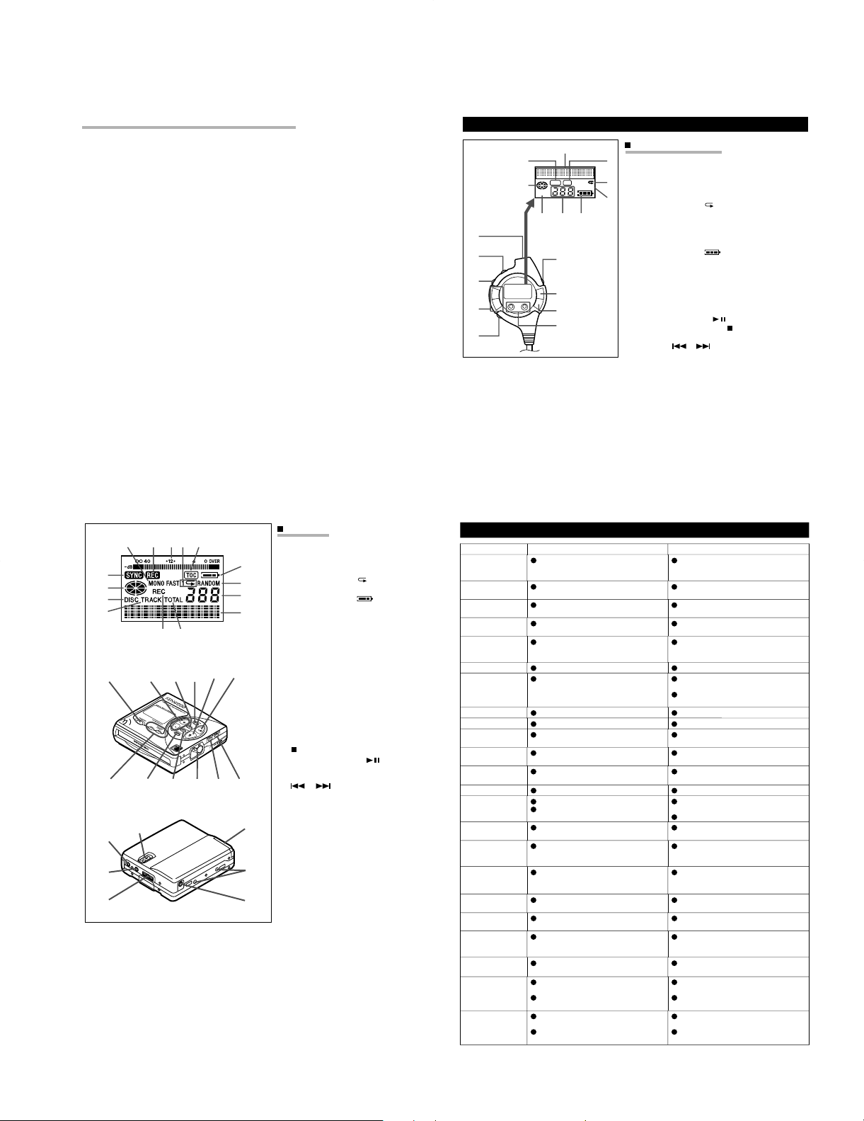
Main Unit
1. Monaural Long-Play Mode Indicator
2. Record Indicator
3. Level Meter
4. Repeat Indicator:
5. TOC Indicator
6. Battery Indicator:
7. Random Indicator
8. Track Number Indicator
9. Character/Time Information Indicator
10. Synchro Recording Indicator
11. Disc Mode Indicator
12. Disc Name Indicator
13. Track Name Indicator
14. Remaining Recording Time Indicator
15. Total Track Number Display
16. Record/Track Mark Button
17. Volume/Name Select Buttons: +, -
18. Display/Lowercase Characters Button
19. Character Button
20. Stop/Power Off/Charge Button:
/OFF
21. Play/Pause Button:
22. Fast Reverse/Fast Forward/Record-
ing LevelControl/Cursor Buttons:
/
23. Enter/Fast Play/Synchro Button
24. Edit/Auto Mark/Time Mark Button
25. Eject Lever
26. Bass/Delete Button
27. Mode/Insert Button
28. Microphone Input Socket
29. Hold Switch
30. Rechargeable Lithium-Ion Battery
Compartment
31. Optical/Line Input Socket
32. Headphones Socket
33. 5V DC Input Socket
34. Battert Case Connection Terminals
12345
6
7
8
9
10
11
12
13
14 15
16 17 18 19 20 21
22
23 24 25 26 27
29
34
30
33
28
31
32
Remote Control Unit
1. Synchro Recording Indicator
2. Character/Time Information
Indicator
3. Record Indicator
4. Repeat Indicator:
5. Random Indicator
6. Disc Mode Indicator
7. Total Track Number Display
8. Track Number Indicator
9. Battery Indicator:
10. Headpones Socket
11. Hold Switch
12. Play Mode Button
13. Volume Buttons: +, -
14. Bass Button
15. Display Button
16. Play/Pause Button:
17. Stop/Power Off Button:
18. Fast Reverse/Fast Forward
Buttons: /
RANDOM
TOTAL
1
REC
SYNC
12
13
14
11
15
16
17
18
10
1
6
2
3
4
5
789
NAMES OF CONTROLS AND INDICATORS
7 Notes about the rechargeable battery
÷ A rechargeable lithium-ion battery is
the only kind that can be used.
Even if the battery supplied with the
unit is not used, you should charge it
at least once every three months
because of the special quality of this
battery.
÷ The rechargeable battery can be
charged approximately 300 times.
÷ Do not use any battery other than
that specified. Use of other batteries maycause malfunctions.
÷ When the operating time is reduced
to about half the normal amount of
time, even after a full charge is performed, replace the battery with a
new one.
÷ When charging or when using the
rechargeable battery, use it within
an ambient temperature range of
5˚C to 35˚C.
÷ If the rechargeable battery is used in
a cold environment, the operating
time will decrease.
Since the rechargeable battery is
vulnerable to damage, please note
the following.
÷ Do not carry the battery in your
pocket or a bag together with metal
objects (keys, coins, jewelry, etc.).
The battery may short out and generate significant amounts of heat.
÷ Do not short-circuit the terminals as
they will become very hot and will
damage the battery.
÷ Do not dip the battery in water, do
not dispose of it in a fire, and do not
take it apart.
To avoid damaging the battery and
shortening its service life, please
note the following.
÷ Do not drop or subject the battery to
shock.
÷ Do not insert objects (metal etc.)
into the battery compartment of this
product or into the rechargeable battery. Do not get the terminals dirty.
If the rechargeable terminals are
dirty, the operating time may be
shortened or it may not be possible
to charge the battery.
÷ After the rechargeable battery is
charged or used, it will get slightly
warm. This is normal.
DMC-J7R
CONTROLS
3
DMC-J7R
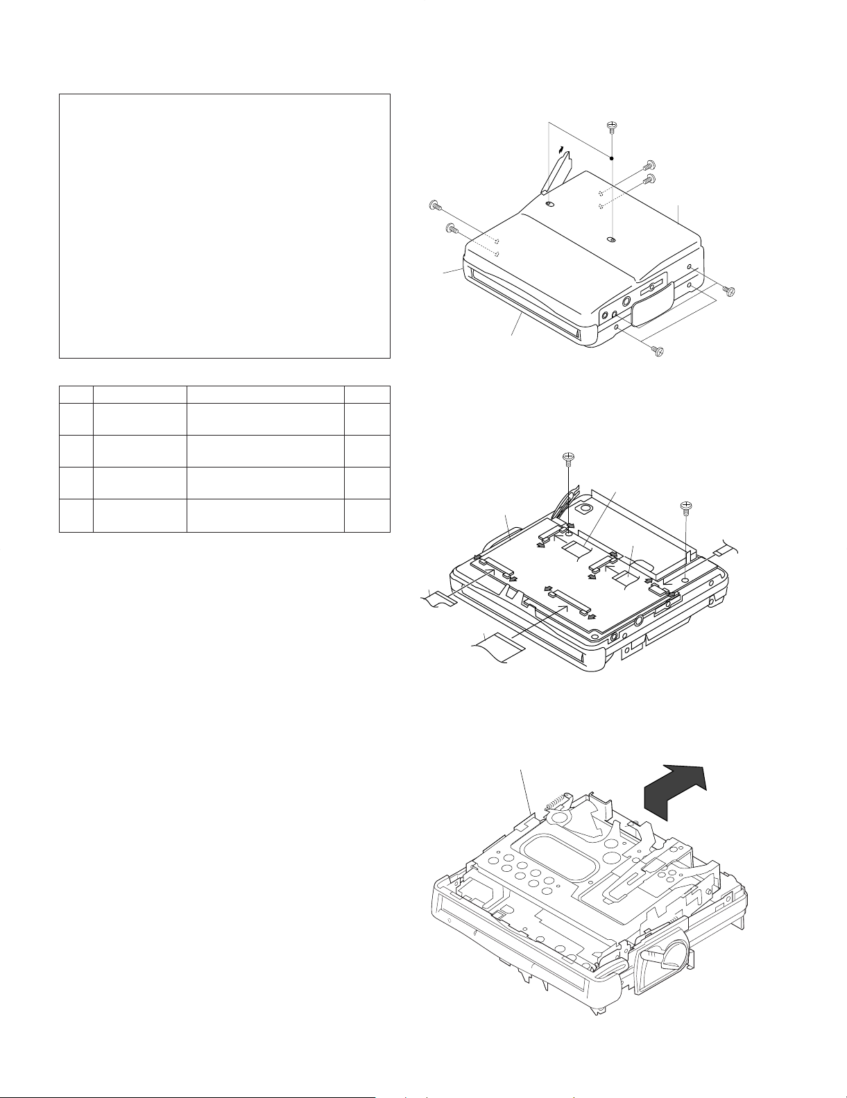
1 Bottom Cabinet 1. Open the battery Lid. 8-1
2. Screw ..................... (A1) x6
2 Top Cabinet 1. Screw ..................... (B1) x4 8-1
2. Flat Cable ...............(B2) x2
3 Main PWB 1. Screw .................... (C1) x2 8-2
2. Flat Cable ...............(C2) x3
4 Mechanism Unit 1. Lift the left side, and remove 8-3
in the arrow direction.
Caution on Disassembly
Follow the below-mentioned notes when disassembling
the unit and reassembling it, to keep it safe and ensure
excellent performance:
1. Take the battery and minidisc out of the unit.
2. When disassembling the machine, be sure to withdraw
the power plug from the socket in advance.
3. When disassemble the parts, remove the nylon band or
wire holder as necessary.
To assemble after repair, be sure to arrange the wires as
they were.
If a screw of different length is fitted to the MD mecha-
nism (the screw of the part to be fitted to the MD
mechanism chassis), it may contact the optical pickup,
resulting in malfunction.
4. When repairing, pay due attention to electrostatic charges
of IC.
REMOVAL
PROCEDURE
STEP
FIGURE
Figu re 8-1
Figure 8-2
Figure 8-3
Caution:
1. Handle carefully the main PWB and flexible PWB.
After removing the flexible PWB (*1) for optical pickup from
the connector, wrap the front end of flexible PWB in conductive aluminum foil so as to protect the optical pickup from
electrostatic damage.
2. When removing the mechanism from the cabinet or when
installing it, it is advisable to
rotate the unit lock plate to lower the holder section.
DISASSEMBLY FOR REPAIR
(A1)x2
Ø1.4x2mm
(B1)x1
Ø1.4x2mm
Center
Cabinet
(C2)x1
(A1)x1
Ø1.4x2mm
Pull
(C2)x1
Top Cabinet
Main PWB
Pull
Pull
(C1)x1
Ø1.7x2.5mm
Pull
Pull
Pull
Pull
Pull
(C2)x1
(B2)x1
(A1)x1
Ø1.4x2mm
Ø1.4x2mm
Ø1.7x2.5mm
Pull
(B1)x1
Bottom Cabinet
(B1)x2
Ø1.4x2mm
(C1)x1
(A1)x2
Ø1.4x2mm
(B2)x1
Mechanism Unit
4
DISASSEMBLY FOR REPAIR
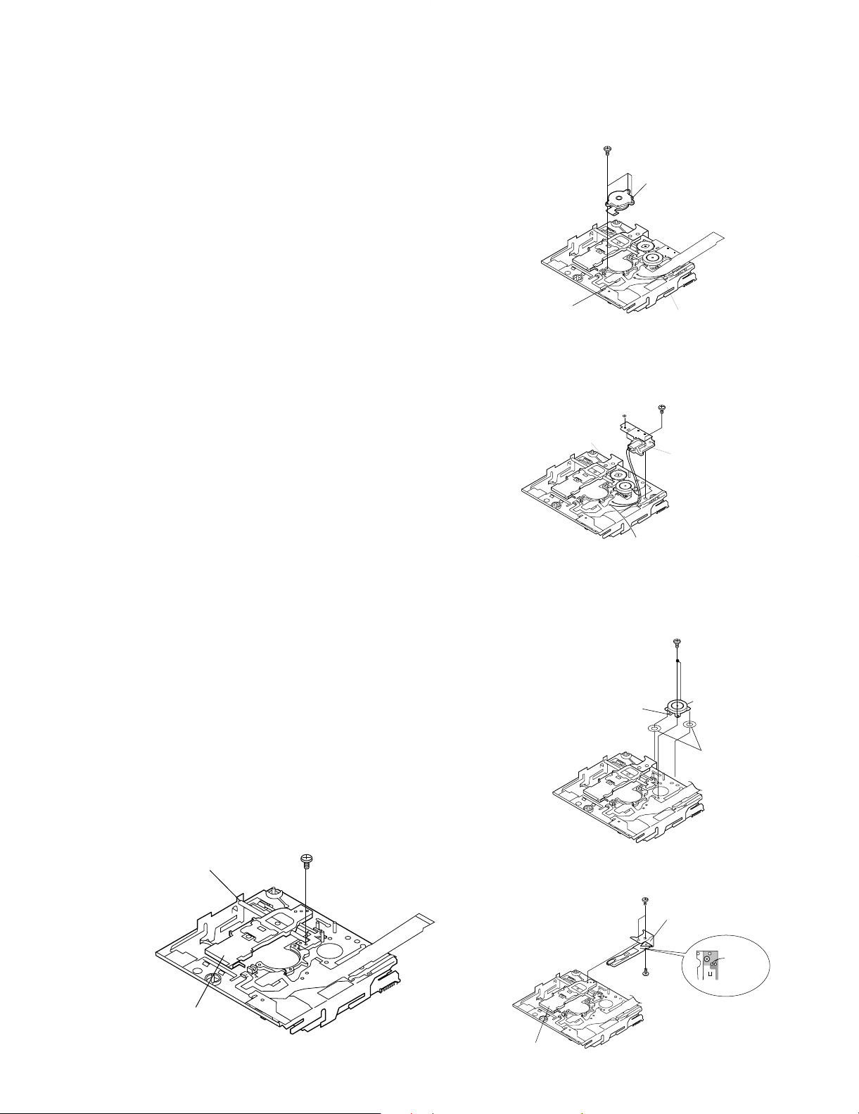
Remove the mechanism according to the disassembling methods 1 to 3. (See Page 8.)
How to remove the spindle motor (See Fig. 9-1.)
1. Remove the solder joint (A1) x 1 of flex PWB.
2. Remove the stop (A2) x 3 pcs. and remove the spindle
motor.
Figure 9-5
Figure 9-1
Figure 9-2
Figure 9-3
How to reinstall the optical pickup unit
(See Fig. 9-5.)
1. Remove the screws (E1) x 1 pcs.
2. Remove the soldering joint (C2) x2 places of flex PWB, and
remove the sled motor.
How to remove the magnetic head
(See Fig. 9-4.)
1. Remove the screw (D1) x 2 pc.
2. Remove the screw (D2) x1 which connects the magnetic
head to the head relay flex PWB, and remove the soldering
joint (D3) x2 pcs.
Note:
Mount carefully so as not to damage the magnetic head.
Figure 9-4
How to remove the lift motor (See Fig. 9-2.)
1. Remove the solder joint (B1) x 2 of slide motor lead wire.
2. Remove the stop washer (B2) x 1 pc., and remove the drive
gear (B3) x 1 PC.
3. Remove the screw (B4) x 1, and remove the lift motor.
Note:
Take care so that the motor gear is not damaged.
(If the gear is damaged, noise is raised in search mode.)
How to remove the sled motor (See Fig. 9-3.)
1. Remove the solder joint (C1) x 2 of slide motor lead wire.
2. Remove the screw (C2) x 2, and remove the sled motor.
Note:
Take care so that the motor gear is not damaged.
(If the gear is damaged, noise is raised in search mode.)
(A2)x3
ø1.4x2.8mm
Flexible PWB
solder joint
(A1) x1
Stop Washer
Drive Gear
(B3)x1
DMC-J7R
Spindle Motor
MDMechanism
(B4)x1
(B2)x1
ø1.4x2.2mm
Lift Motor
(E1)x1
ø1.7x2.5mm
Shaft
(B1)x2
Remove the solder joint
(C2)x2
Mecha Flexible PWB
solder joint
(D1)x2
Ø1.4x1.8mm
(C1)x2
ø1.4x1.2mm
Sled Motor
Washer x2
Magnetic Head
Pickup Unit
Pickup Unit
(D1)x1
Ø1.4x1.5mm
Solder
joint
(D3)x2
5
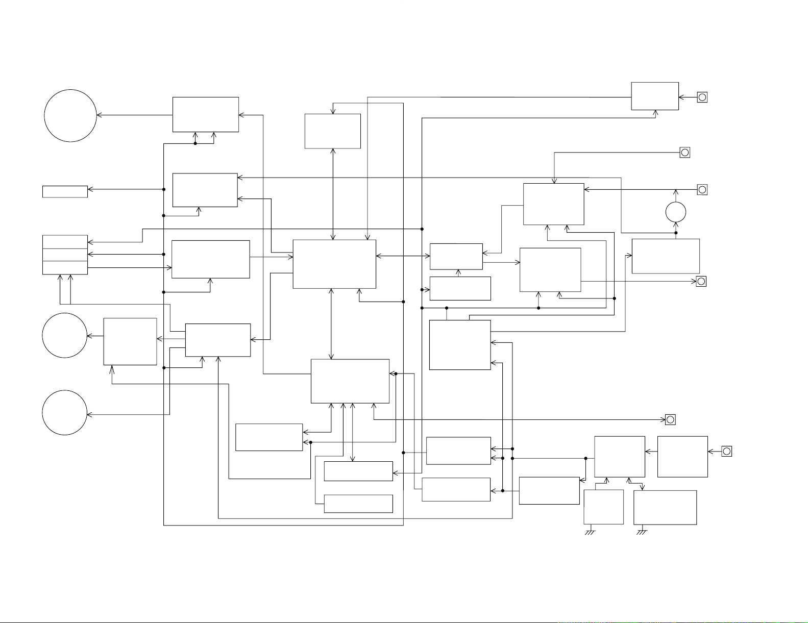
6
LASER
HEAD
LIFT
MOTOR
MOTOR
DRIVER
SPINDLE
MOTOR
SLED
MOTOR
SPINDLE
MOTOR
DRIVER
(BA6965FV)
VCC VS
HEAD
DRIVER
VS
VCC
RF SIGNAL
PROCESSOR
(IR3R55)
PICK COIL
DRIVER
VCC VM
4 M
D-RAM
(IC202)
ENDEC
ATRAC
(LB37648B)
SYSTEM
MICROCOMPUTER
E2-PROM
DISPLAY UNIT
OPERATION UNIT
AD/DA
CONVERTER
POWER
DRIVER
2.5V
REGULATOR
+2.8V
-2.8V
(IR3M09)
VCC
POWER DRIVER
(IR3M09)
2.5V
REGULATOR
(ON/OFF)
(IR3R54N)
AUDIO AMP.
VCC VEE
(IR3R54N)
AUDIO AMP.
VCC VEE
+6~8
DC IN
RIPPLE
FILTER
DIGITAL INPUT
OPTICAL
INPUT UNIT
LINE INPUT
LINE OUT
MIC IN
HEAD PHONES
4.5V
REGULATOR
(ON/OFF)
REMOTE CONTROL
POWER SELECT
N-ch MOS FET
3V
DC/DCONVERTER
BATTERY
VOLTAGE
REGULATOR
CONSTANT
CURRENT DRIVE
RECHARGEABLE
BATTERY
OPIC
POWER SELECT
CHARGE DRIVER
VCC
+2.8
+2.5
F
IC901
+2.5
(LB1638) IC651
+2.5
+2.2
+2.5
+2.5
+2.5
+2.5
+2.5
(74ACT02)
IC351
IC101
IC601
IC201
IC401
+2.5
IC402
+2.8
IC501
+2.5P
IC771
+2.8
IC841
IC821
+2.5
+2.5
IC875
IC701
+2.8V
-2.8V
IC703
+2.8V
-2.8V
J701
+4.5
J701
J702
Q721
IC702
J703
IC801,803,804
+1.8~5.5V
IC871
3~5V
(1.8~3.4V)
IC800,805,Q801
(2.9~4.1V)
J801
DC JACK
(4~5.5V)
PICK
T
DMC-J7R
BLOCK DIAGRAM
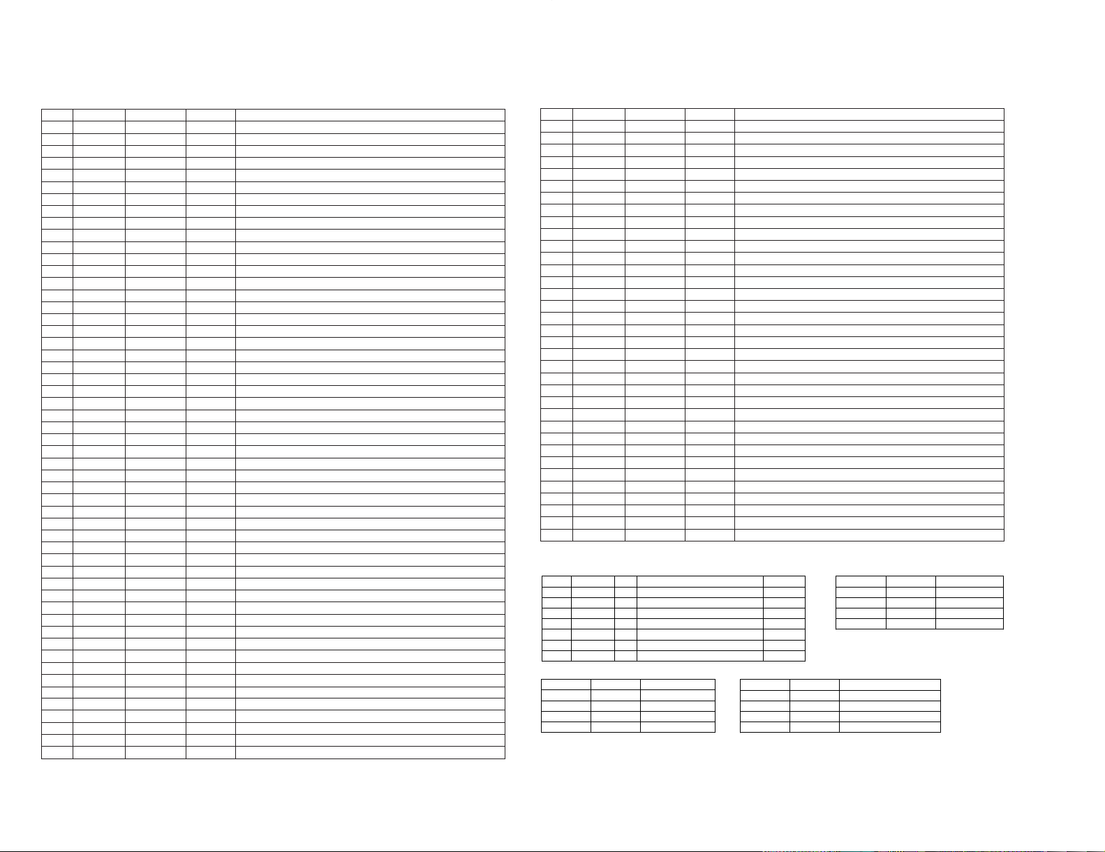
66 P52 RCLAT Output Record audio
67 P53 PBOPON Output Audio IC output stage control output
68 P54 MCPGIN Input Mic plug insertion detection input
69 P55 INPGIN Input Line/digital plug insertion detection
70 P56 INPGCK Input Line/digital plug type detection
71 P57 RCPCNT Output Record circuit power control output
72 VSS VSS Output Ground potential
73 P60 EMPHO Output Audio emphasis control output 0
74 P61 HPLAY Input Main unit PLAY key operation detection input
75 P62 HREC Input Main unit REC key operation detection input
76* P63 RTCCE Output Clock IC chip enable control output
77* P64 RTCWR Output Clock IC read/write control output
78 P65 CEDT In/Output Clock/EEPROM serial data input/output
79 P66 CECK Output Clock/EEPROM serial data input/output
80 P67 EPCS Output EEPROM chip selection output
81 VDD VDD Output Positive power supply
82 T15 SPIN Inout Spindle motor FG pulse detection input
83* P101 P101 Output Spare for sled motor control
84* P102 TEST0 Input Test mode setting input 0
85* P103 TEST1 Input Test mode setting input 1
86 P30 PSLINN Output Built-in battery power selection output
87 P31 PSLDCI Output DC jack power selection output
88 P32 PSLDRY Output Dry cell power selection output
89* P33 P33 Output Spare for sled motor control
90 P34 ELON Output Remote controller EL light control output
91 T100 CIN Input Truck cross signal detection input
92 P36 PHOLD Output Dry cell power ON holding output
93 P37 PCNT1 Output Power IC VREF feed control output
94 TEST/VPP VPP Output Test/R-ROM write power input
95 P90 PCNT2 Output Power IC VCC feed control output
96 P91 CKSTP Output Main clock stop control output
97 P92 DISCIN Input Disk insertion detection input
98 P93 INNSW Input Mechanism inner SW position detection input
99 P94 DISCPR Input Record enable/disable switch detection input
100 P95 PDCNT Output PD current control output for inner detection
Pin No.
FunctionPort Name Terminal Name
Input/Output
In this unit, the terminal with asterisk mark (*) is (open) terminal which is not connected to the outside.
Table1: TEST PORT
Table2: EMPHASIS PORT
TEST1 TEST0 Description
EMPH1 EMPH0 Description
H H Normal mode
H H fs: 32kHz ON
H L No adjustment
H L fs: 48kHz ON
L H Test mode
L H fs: 48kHz OFF
L L Prohibition
L L fs: 44.1kHz ON
Table3: LDCNT PORT
EMPH1 EMPH0 Description
H H Brake
HL UP
L H DOWN
L L OFF
SYSTEM LSI EXTENSION PORT(IC:201/LR37648)
Pin No. Port Name I/O Descriptions Remarks
52,53 LDCNT1,2 O Recording head up/down control port. table3
54 - O No use open
55 EMPH1 O Audio emphasis control port. table2
56 DCNT1 O Mechanism driver enable port. H= enable
57 OPTCNT O Power on/off for optical input circuitry. H= on
58 DAPON O D/A converter control port H=work
59 ADPON O A/D converter control port H=work
1 P120 SWP UP Output Asterisk input Output for pull-up
2*~7* P121~P126 P121~P126 Output Not used
8 P127 OEM Input Product brand ID input
9 VDD VDD Input Positive power supply
10* X2 X2 Input Not used
11 X1 X1 Input Main system clock input
12 VSS VSS Input Ground potential
13* XT2 XT2 Input Not used
14 XT1 XT1 Input Subsystem clock input
15 RESET RESET Input Microcomputer hard reset input
16 INPUT0 DINT Input System LSI interruption request input
17 P01 SENSE Input System LSI servo sense input
18 P02 FOK Input Focus OK signal input
19 P03 XRST Outout System LSI hard reset output
20* P04 P04 Output Not used
21 P05 HDON Output Record head current control output
22 P06 VLIM Intput Volume limiting switch input
23 AVDD AVDD Input A/D converter analog positive power
24 AVREF0 AVREF0 Input A/D converter reference voltage input
25 ANI0 PLVINN Input Built-in battery voltage detection input
26 ANI1 PLVDCI Input DC jack voltage detection input
27 ANI2 PLVDRY Input Dry cell voltage detection input
28 ANI3 RKEY Input Remote controller key operation detection input
29 ANI4 HKEY1 Input Main unit key operation detection input 1
30 ANI5 HKEY2 Input Main unit key operation detection input 2
31 ANI6 TEMP Input Ambient temperature detection input
32 ANI7 CNTRY Intput Product destination ID input
33 AVSS AVSS Intput A/D converter ground potential
34 ANO0 LDVAR Output P.U. laser power set output
35* ANO1 MDOUT Output Internal motion mode output
36 AVREF1 AVREF1 Output D/A converter reference voltage input
37 P70 SYWR Output System LSI write enable output
38 P71 SYRD Output System LSI read enable output
39 P72 SYRS Output System LSI register selection output
40 P20 - Output Not used
41 SO1 RMDAT Output Remote controller display data output
42 P22 - Output
43 P23 HSTOP Input Main unit STOP key operation detection input
44 P24/BUZ BEEP Output Beep tone pulse output
45 P25 DSPSTB Output Main unit display control strobe output
46 SO0 DSPDAT Output Main unit display control serial data output
47 SCK0 DSPSCK Output Main unit display control serial clock output
48~55 P80~P87 SYD0~SYD7 In/Output System LSI parallel data bus
56 P40 EJECT Input Eject lever operation detection input *
57 P41 KHOLD Input Main unit key hold switch input
58 P42 RPLAY Input Remote controller PLAY key operation detection input
59* P43 HFON Output P.U. high frequency superposition control output
IC401 RH-iX2680AF03(IX2680AF):System Microcomputer
Pin No.
Function
Port Name
Terminal Name Input/Output
In this unit, the terminal with asterisk mark (*) is (open) terminal which is not connected to the outside.
60 P44 LDON Output P.U. laser ON/OFF control output
61 P45 OPICGA Output P.U. detection sensitivity selection output
62 P46 RFLAT Output RF amp. IC data latch output
63 P47 RACLK Output RF/audio IC data clock output
64 P50 RADAT Output RF/audio IC serial data output
65 P51 PBLAT Output Playback audio IC data latch output
7
CIRCUIT DESCRIPTION
DMC-J7R
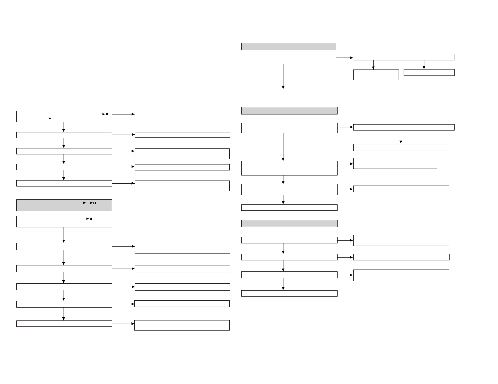
8
Yes
Check whether there is defective solder joint of audio signal
line between IC703 and J703
No
Yes
Is audio wavefrom output from J703 pins 3 and 4.
Check the pins 5 and 6 of IC703.
No
Yes
Is audio wavefrom output from IC703 pins 18 and 19.
Check IC201 pins 70 to 72, pin 74 and IC501 pins 9, 10, 11,
15
No
• Abnormal display
No
Yes
Is waveform output from IC 401 pins 45 to 47?
Check for pattern breakage of flexible PWB, check for
defects of display microcomputer (replace the display unit).
Is waveform output from CNS 482 pins 1 to 3?
Are the pin7 (VCC) and pin 6 (GND) normal?
• Playback state cannot be set
Is initialization performed normally in case of high- reflection
disc playback?
Yes
Check between IC401 and
CNS482.
No
Check the periphery of IC401.
Does the playback time display advance?
Yes
Position check in INNER mode
Check IC201 and IC202 connection line.
Is the lead-in photointerrupter set to OFF when the optical
pickup moves to the innermost periphery in NORMAL mode?
(Is TP660 in H level?).
Check the lead-in photointerrupter, mechanical flex
PWB soldering and CNS601 connection.
No
Ia an attempt to repeat repeatedly the TOC part performed
on the low-reflection disc?
Yes
No
No
Replace the disc.
No
• Audio playback clrcult
When it has been ascertained that the address up to cluster address is normal in the TEST mode.
Yes
Is audio wavefrom output from IC501 pins 19 and 20?
Check headphones jack,and periphery of headphone.
Although the playback time display is acting., no sound is given during playback in the normal mode.
It is advisable to use the TEST mode (refer to Error Data Display Mode, P15) indicating the causes of troubles before
starting repair. Causes of operation errors (up to 10 errors) are recorded as error codes. This information is useful
for repair.
When does not function
When the CD section does not operate When the objective lens of the optical pickup is dirty,this section may not operate.Clean
the objective lens,and check the playback operation.When this section does not operate even after the above step is taken,check
the following items.
Remove the cabinet and follow the troubleshooting instructions.
"Track skipping and/or no TOC(Table Of Contents) may be caused by build up of dust other foreign matter on the laser pickup lens.
Before attempting any adjustment make certain that the lens is clean. If not, clean it as mentioned below."
Turn the power off.
Gently clean the lens with a lens cleaning tissue and a small amount of isopropyl alcohol.
Do not touch the lens with the bare hand.
Is the power supply turned on when the remote control
button or main unit button is pressed?
No
Perform the check stated in item "Power is not turned on
when the PLAY button is pressed".
Perform the check stated in item "Abnormal display".
No
Yes
Does the display operate normally?
Is playback state set?
Yes
Perform the check stated in item "Playback state connot be
set".
No
Is audio output normal?
Yes
Perform the check stated in item "Audio playback circuit".
No
Is recording/playback operation normal?
Yes
Perform the check stated in item "Recording/playback
operation".
No
• Power is not turned on when the / button
is pressed.
No
No
Yes
Check the periphery of remote controller and main unit
headphone terminal (J703) and IC401.
No
Is the pin 57 of IC401 in H state?
Is operation normal when the main body button is pressed?
Check the position of Hold switch.
Is power turned on when the remote control button is
pressed?
No
Are IC401 pin 97 set to "L"?
Check the DISC IN (SW901) switch of mechanism PWB.
Yes
Yes
Is clock supplied to the pins 11 and 14 of IC401?
No
Check that voltage is applied to the periphery of IC403.
Yes
Is 2.5V applied to TP811?
No
Check whether there is solder touch of part connected to
the +2.5V line.
DMC-J7R
TROUBLE SHOOTING
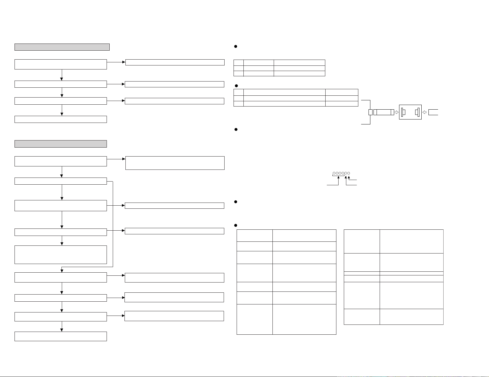
1 High reflection disc TG YS-1 (SONY)
2
Low reflection disc Recording minidisc
Test disc
MD adjustment needs two types of disc, namely recording disc (low reflection disc) and playback-only disc (high
reflection disc).
Type
Test disc
Note: Use the low reflection disc on which music has been recorded.
EEPROM version
Destination
Leaving the TEST mode
(1) Press the STOP button in the TEST mode stop state or version indicating state or whole LCD lighting state.
(2) EEPROM rewrite-enable area updating, adjustment error setting (so as to adjust all the items when the power supply is turned
on in the normal mode)
(3) Change to standby state
Test Mode
1. AUTO 1 Mode • Perform preliminary automatic adjustment.
• If the combination of mechanism and pickup
PWB has been changed, be sure to start from
AUTO1.
2. AUTO 2 Mode • Perform ATT (attenuator) automatic adjustment.
• Perform continuous playback (error rate display,
jump test)
3.
✻
✻
✻
✻
✻
✻
✻
✻
MANUAL 1 Mode • Temperature is displayed. (Updating in realtime)
• Seeing the displayed adjustment value, perform
preliminary manual adjustment.
(Error rate indication, jump test)
4. MANUAL 2 Mode • Temperature is displayed. (Updating in realtime)
• Seeing the displayed adjustment value
perform manfully the preliminary adjustment.
(Error rate indication, jump test)
• Continuous playback is performed
(error rate display, jump test).
5. RESULT 1 Mode • The value adjusted in AUTO1 or MANUAL1 is
indicated.
• (Execution in servo "OFF" state").
6. RESULT 2 Mode • The value adjusted in AUTO 2 or MANUAL 2 is
indicated.
• Adjustment value is changed manually.
(error rate display, jump test).
7. TEST-PLAY Mode • Continuous playback from the specified address
is performed.
• 1 line, 10 lines or 400 lines manual jump is
performed.
• C1 error rate display (pit section), ADIP error
rate display (groove section)
• The temperature correction is performed only
when servo start is performed, but the posture
correction is not performed duringcontinuous
playback.
Microcomputer version
Entering the TEST mode
1. Setting at port (in standby state, disc-free state or power nonconnected state)
(1) Set the port as follows.
TEST1 : "Low"
TEST0 : "High"
(2) Press the PLAY button in the standby state (it is allowed to insert the disc or to connect the power supply).
(3) Test Mode STOP [ _ T E S T _ ]
2. Setting by special button operation (in standby state)
(1) Holding down the DISP button and ENTER button, press the PLAY button.
(2) Normal mode setting initialization (BASS setting, VOL setting, etc.)
(3) Indication of microcomputer version for one second [ ]
(4) Whole LCD lighting for 2 seconds
(5) Test Mode STOP [ _ T E S T _ ]
*When the PLAY button is pressed during indication (3) and (4), the process proceeds to (5).
8. TEST-REC Mode • Continuous record from the specified address is
performed.
• Change of record laser output(servo gain is also
changed according to laser output).
• The temperature correction is performed only
when servo start is performed, but the posture
correction is not performed during continuous
recording.
9. NORMAL Mode • The mode is changed from the TEST mode to
the normal mode without adjustment.
• In the normal mode the internal operation mode,
memory capacity, etc. areindicated.
• In the normal mode both temperature correction
and posture correction are perfomed.
10. DIGITAL INPUT mode • Digital input information is displayed.
11.
ERROR INFORMATION
• Error information is displayed.
Mode • Error information is initialized
12. E2-PROM Mode • Factors of digital servo are changed manually.
(Each servo is turned on individually.)
• Cut-off frequency of BASS1, BASS2 and BASS3
is selected manually.
• Temperature detection terminal voltage is
measured, and the reference value is set.
• Defaults are selected and set.
• Setting of EEPROM protect area is updated.
(In case of protect releasing)
13. INNER
These modes are not used for service.
Mode • Determine the position where the INNER switch
is turned on. (only high reflection disc).
• The temperature correction is performed only
when servo start is performed, but the posture
correction is not performed.
Type
Parts No.
1 Flat Cable for servicing 16Pin QCNWK0110AFZZ
2 Extension Connector for Service 16Pin RUNTK0460AFZZ
Extension Cable (See Fig.10)
Figure 10
Mecha Flexible PWB
16 pin
16 PIn
CN601
QCNWK0110AFZZ
16pin Flat Cable
RUNTK0460AFZZ
Extension PWB for servicing 16pin
PWB side
• The spindle motor fails to run.Does the head move
No
Does the waveform appear on the IC201 pins 24 and 25 after
TEST mode AUTO2 completion and in this state?
Check the IC201 periphery.
Yes
Does waveform appear on the IC601 pin 13?
Does waveform appear on IC901 pins 1, 19 and 20?
Replace the spindle motor.
Yes
No
L608, IC201, IC901, CN601 and flex, etc. soldering check
No
Replace. IC601
Yes
• Recording/playback operation
Insert a low reflection disc, and ascertain audio output by normal playback, and then set TEST REC mode.
Yes
Does the head move down, failing to start record even
when the continuous record mode is set after address?
Check voltage of pins 52 and 53 of IC201, pins 2, 4, 7, and 9 of
IC651, pins 3 and 4 of CNS601. Check whether disc is recordinhibited.
No
Does the RF waveform of TP201 appear when playback is
Does level of pins 34 of IC401 and pin 17 of IC101 change
depending on record and playback?
Is RF pattern output from IC201 pin 50?
Yes
No
Check for soldering failure of IC201 .
No
Check periphery of IC401 and IC101.
Check whether there is any damage in IC101, periphery of
laser diode.
Yes
Check for defects of IC351 in head drive flexible PWB,
Q351 to 354, head, flexible PWB.
No
Yes
Is audio monitor output given in normal mode LINE IN
record?
Check waveforms of pins 9 to 12 of IC501, pins 70 to 73 of
IC201.
Is waveform obtained on IC501 pins 3 and 6?
No
Yes
Check whether the pin 7 of IC501 and the pin 59 of IC201 are in
H state.
No
No
Does voltage on the IC701 pins 13 to 15 change in case of
record VOLUME UP/DWN?
Is audio waveform observed on the pins 18 and 19 of
IC703?
Yes
Check whether input waveform is observed on the pins 5
and 6 of IC703.
Yes
9
TROUBLE SHOOTING
DMC-J7R
 Loading...