


TECH SHEET - DO NOT DISCARD |
PAGE 1 |
|
|
|
|
|
|
Models: |
|
|
|
|
|
665.61682101 |
|
Electrical Shock Hazard |
665.61683101 |
|
665.61684101 |
|
|
Disconnect power before servicing. |
|
|
665.61689101 |
|
|
Replace all panels before operating. |
|
|
Failure to do so can result in death or electrical shock. |
|
|
|
|
PRECAUTIONS TO BE OBSERVED BEFORE AND DURING SERVICING TO AVOID POSSIBLE EXPOSURE TO EXCESSIVE MICROWAVE ENERGY
a.Do not operate or allow the oven to be operated with the door open.
b.Make the following safety checks on all ovens to be serviced before activating the magnetron or other microwave source, and make repairs as necessary:
1.Interlock Operation
2.Proper Door Closing
3.Seal and Sealing Surfaces (Arcing, Wear & Other Damage)
4.Damage to or Loosening of Hinges & Latches
5.Evidence of Dropping or Abuse
c.Before turning on microwave power for any service test or inspection within the microwave generating compartments, check the magnetron, waveguide or
transmission line and cavity for proper alignment, integrity and connections.
d.Any defective or misadjusted components in the interlock, monitor, door seal, and microwave generation, and transmission systems shall be repaired, replaced, or adjusted by procedures described in service manual before the oven is released to the owner.
e.A microwave leakage check to verify compliance with the Federal performance standard should be performed on each oven prior to release to the owner.
f.Do not attempt to operate the oven if the window area of the door is broken.
POWER OUTPUT MEASUREMENT
The power output of the magnetron can be measured by the following tap water temperature rise test:
Be sure oven cavity is clean and cool (not used recently).
Check the line voltage during this test. Low voltage will lower the magnetron output.
1.Fill a glass beaker with 1000 ml (32 oz.) of tap water. Stir the water with a thermometer (digital recommended) and record the temperature. This starting temperature should be between 10°C (50°F) to 24°C (75°F).
2.Place the beaker in the center of the oven. Operate on HIGH power level for 60 seconds.
3.When done, stir the thermometer through the water and record the temperature.
4.Subtract the cold water temperature from the warm water temperature to get the temperature rise. Normal range is as shown in the following table:
Voltage |
Temperature Rise |
|
(VAC under load) |
°C |
°F |
120V |
11 - 14 |
19.8 - 25.2 |
108V |
9.5 - 12.5 |
17.1 - 22.5 |
FAILURE CODES/INDICATIONS
Display |
Likely Failure |
|
Recommended Repair Procedure |
|
Condition |
|
|||
|
|
|
||
Flashing |
Power Failure |
After a power failure, the colon “:” will be flashing. Press any key to end this indication. |
||
colon “:” |
The colon will then be steady when in standby. |
|||
|
||||
-F2- |
Keyboard Failure |
Replace membrane switch. If problem persists, replace control system assembly. |
||
-F3H- |
Humidity Sensor |
Connect a new sensor to the board (at P5). If no failure code appears when starting sensor |
||
Failure |
function, replace old sensor. Otherwise, replace control system assembly. |
|||
|
||||
-F3T- |
Temperature |
1. |
Check that the oven temperature is not below 5°C (41°F) or above 60°C (140°F). |
|
Sensor Failure |
2. |
If problem persists, replace the control system assembly. |
||
|
||||
|
|
1. |
Unplug the oven for at least 40 seconds. Check to see if this solves the problem. |
|
|
|
|
(Possible reason: Over temperature protection for the magnetron operated earlier.) |
|
-F7- |
1100W Inverter |
2. |
Check the resistance of the magnetron thermostat. It should be close to 0 ohms. |
|
Failure |
3. |
Check wiring to the 1100W inverter and control system. |
||
|
||||
|
|
4. |
Replace 1100W inverter. |
|
|
|
5. |
If problem persists, replace control system assembly. |
|
NOTE: If lights work, but cooling fan does not, 40W inverter may have failed. See “Checking Inverters” on page 11.
FOR SERVICE TECHNICIAN'S USE ONLY |
PART NO. 4619-651-97964/8184640 |
PAGE 2 |
TECH SHEET - DO NOT DISCARD |
|
|
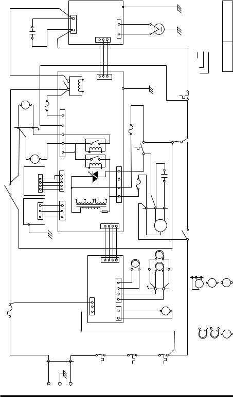
SCHEMATIC |
|
|
|
|
|
|
|
|
|
|
|
|
<![if ! IE]> <![endif]>E701 |
|
|
|
|
|
|
|
|
|
|
|
|
||||||
DIAGRAM |
|
|
|
|
|
|
|
|
<![if ! IE]> <![endif]>INVERTER |
|
|
|
|
41 Y/G18 |
|
|
|
|
|
|
|
|
<![if ! IE]> <![endif]>BROWN-COLORWIRE |
||||||||
| <![if ! IE]> <![endif]>R1637 |
|
|
<![if ! IE]> <![endif]>CapacitorFilter |
|
|
|
<![if ! IE]> <![endif]>GR2249 |
|
|
|
<![if ! IE]> <![endif]>CN702 |
<![if ! IE]> <![endif]>1100W |
<![if ! IE]> <![endif]>26AWG/3C46 |
<![if ! IE]> <![endif]>CN701 |
|
<![if ! IE]> <![endif]>CN703 |
|
|
|
|
|
|
|
|
|
<![if ! IE]> <![endif]>GR1650 |
<![if ! IE]> <![endif]>AWG16-SIZEWIREBR16 |
||||
|
|
|
|
|
|
38 R22 |
|
|
|
|
|
|
|
|
|
|
|
|
|
|
|
|
|
|
|
|
|
|
|
||
|
|
|
|
|
|
|
|
|
|
|
|
|
|
|
|
|
|
|
|
40 W18 |
|
MAGNETRON |
|
|
|
|
|
||||
|
|
|
|
|
|
|
|
|
|
|
|
|
|
|
|
|
|
|
|
|
|
|
|
|
|
|
|
|
|
||
|
|
|
|
|
|
|
|
|
|
|
|
|
|
|
|
|
|
|
|
39 W18 |
|
|
|
|
|
|
|
|
|
|
|
|
|
|
|
|
|
|
|
|
|
|
|
|
|
|
1 |
|
|
|
|
|
|
|
|
|
|
|
|
|
|
|
|
|
|
|
|
|
|
|
|
|
50 GR16 |
|
|
|
|
|
|
|
|
|
|
|
|
|
|
|
|
|
|
|
|
||
| <![if ! IE]> <![endif]>R1629 |
<![if ! IE]> <![endif]>BL2225 |
<![if ! IE]> <![endif]>5P11 |
<![if ! IE]> <![endif]>TT |
<![if ! IE]> <![endif]>BL2226 |
<![if ! IE]> <![endif]>6P11 |
|
|
|
P141 |
<![if ! IE]> <![endif]>NFSSMDoorTT |
<![if ! IE]> <![endif]>2 1 |
<![if ! IE]> <![endif]>4903 |
<![if ! IE]> <![endif]>MWRelay |
<![if ! IE]> <![endif]>DISPLAYPCB |
<![if ! IE]> <![endif]>POWER& PCB |
|
|
<![if ! IE]> <![endif]>GND |
<![if ! IE]> <![endif]>FUSE |
<![if ! IE]> <![endif]>Amp.4 |
|
<![if ! IE]> <![endif]>FanExhaust |
<![if ! IE]> <![endif]>Thermostat |
10 BR22 |
<![if ! IE]> <![endif]>Magnetron Thermostat |
<![if ! IE]> <![endif]>BL1632 |
<![if ! IE]> <![endif]>1 |
<![if ! IE]> <![endif]>GREENG:OR: ORANGE |
|||
|
|
|
1 |
|
|
<![if ! IE]> <![endif]>WHITEW:BR: BROWN |
|||||||||||||||||||||||||
|
|
|
|
|
|
|
|
|
|
|
|
|
|
|
|
<![if ! IE]> <![endif]>P2 |
|
|
|
42 Y/G18 |
|
|
<![if ! IE]> <![endif]>BL22 |
|
|
|
|
|
|||
|
|
|
|
|
<![if ! IE]> <![endif]>BL22 31 |
30 OR22 |
|
|
|
|
|
|
|
|
|
|
|
<![if ! IE]> <![endif]>BR22 11 |
|
|
|
|
<![if ! IE]> <![endif]>31 |
|
|
|
|
|
|||
|
|
|
|
|
53 OR220.25Amp. |
|
|
|
|
|
|
|
|
|
|
|
|
|
|
|
|
|
|
|
|
||||||
|
|
|
|
|
|
|
<![if ! IE]> <![endif]>FUSE |
|
|
|
|
|
|
|
|
|
|
|
|
|
|
|
|
|
|
|
|
|
|
|
|
|
|
|
27B22 External KeyboardSM |
|
34 R22 |
|
|
|
<![if ! IE]> <![endif]>4901 4906 |
|
|
|
|
|
|
|
|
|
|
|
|
|
<![if ! IE]> <![endif]>CapacitorMotor |
|
|
|
|
|
|||
|
<![if ! IE]> <![endif]>28W22 |
|
P71 |
<![if ! IE]> <![endif]>35GR22 |
<![if ! IE]> <![endif]>26AWG/4C47 |
<![if ! IE]> <![endif]>1 |
<![if ! IE]> <![endif]>P7 |
|
|
|
|
|
|
|
|
<![if ! IE]> <![endif]>52BR22 |
<![if ! IE]> <![endif]>FUSE |
<![if ! IE]> <![endif]>Amp.4 |
<![if ! IE]> <![endif]>13W22 |
<![if ! IE]> <![endif]>W2214 |
<![if ! IE]> <![endif]>R22 |
<![if ! IE]> <![endif]>Interlock |
<![if ! IE]> <![endif]>Monitor |
|
<![if ! IE]> <![endif]>B:BLACK |
<![if ! IE]> <![endif]>BL:BLUE |
|||||
|
|
|
|
|
|
|
|
|
|
<![if ! IE]> <![endif]>CL |
|
|
|
|
|
|
|
|
|
|
|
<![if ! IE]> <![endif]>Y22 |
|
|
|
|
|
|
|
|
|
|
|
|
|
|
|
|
|
|
|
|
|
|
<![if ! IE]> <![endif]>Prim. Sec. 7103 |
|
|
|
|
<![if ! IE]> <![endif]>N1 L1 HLHF |
|
|
|
<![if ! IE]> <![endif]>12 |
|
|
|
|
|
|
|
<![if ! IE]> <![endif]>P2/P3/P5/P7/P12/P14/CN1/CN151/ |
<![if ! IE]> <![endif]>CN152/CN153/CN701/CN702/CN703: |
| <![if ! IE]> <![endif]>Interlock Secondary |
<![if ! IE]> <![endif]>Y169 |
|
<![if ! IE]> <![endif]>Humidity |
|
|
|
|
<![if ! IE]> <![endif]>W R B |
<![if ! IE]> <![endif]>1 |
<![if ! IE]> <![endif]>P5 |
<![if ! IE]> <![endif]>TR1-5101 |
<![if ! IE]> <![endif]>L.V.T. |
|
|
<![if ! IE]> <![endif]>26AWG/4C |
<![if ! IE]> <![endif]>P3 |
P121 |
|
<![if ! IE]> <![endif]>B2217 |
<![if ! IE]> <![endif]>B20 16G22 |
<![if ! IE]> <![endif]>1P10 |
<![if ! IE]> <![endif]>W20 |
<![if ! IE]> <![endif]>FH |
<![if ! IE]> <![endif]>3P10 Y169 |
|
|
<![if ! IE]> <![endif]>33W16 |
||||
|
|
|
|
|
|
|
|
|
|
|
|
|
|
|
|
|
|
|
|
51 G22 |
|
|
|
<![if ! IE]> <![endif]>15 |
|
|
|
|
|
|
|
|
|
|
|
<![if ! IE]> <![endif]>Sensor |
|
|
|
|
|
|
|
|
|
|
|
|
|
|
|
|
|
|
|
|
<![if ! IE]> <![endif]>2P10 R20 |
|
|
|
|
|
|
|
|
|
|
|
|
|
|
|
|
|
|
|
|
|
|
1 |
|
|
|
|
|
|
|
|
|
|
|
|
|
|
|
| <![if ! IE]> <![endif]>FUSE BR168OR16 |
<![if ! IE]> <![endif]>Amp.20 |
|
|
43 Y/G18 |
|
|
|
<![if ! IE]> <![endif]>BL2219 |
|
|
|
|
<![if ! IE]> <![endif]>INVERTER |
|
<![if ! IE]> <![endif]>CN152CN153 |
<![if ! IE]> <![endif]>11 |
|
|
|
<![if ! IE]> <![endif]>W2223 TR22 |
|
<![if ! IE]> <![endif]>1P11 Y22 |
2P11CF |
|
<![if ! IE]> <![endif]>Interlock |
Primary18BL16 |
SYMBOLNOTES HF CAVITYLAMPCL |
||||
|
|
|
|
|
|
|
|
|
|
<![if ! IE]> <![endif]>1 |
<![if ! IE]> <![endif]>CN1 |
|
<![if ! IE]> <![endif]>P22 |
|
|
<![if ! IE]> <![endif]>TR22 |
|
||||||||||||||
|
|
|
|
|
|
|
|
|
|
|
|
|
|
<![if ! IE]> <![endif]>40W |
<![if ! IE]> <![endif]>45 |
<![if ! IE]> <![endif]>CN151 |
|
|
<![if ! IE]> <![endif]>P22 |
|
|
|
<![if ! IE]> <![endif]>L H L H |
<![if ! IE]> <![endif]>W22 24 Y22 |
|
|
|
<![if ! IE]> <![endif]>EXHAUST HOOD |
<![if ! IE]> <![endif]>MOTOR FAN |
||
|
|
|
|
|
|
|
|
|
|
|
|
|
|
|
|
1 |
|
|
|
|
<![if ! IE]> <![endif]>CL |
|
|
|
|
|
|
|
|
|
|
|
|
|
|
|
|
|
|
|
|
|
|
|
|
|
|
|
|
|
|
|
|
|
|
|
|
|
|
|
|
|
|
|
|
|
|
|
|
|
|
|
|
|
|
|
|
|
|
|
|
|
|
|
21 W22 |
|
|
|
|
|
|
|
|
|
|
|
|
|
|
|
|
7 R22 |
|
|
|
|
|
|
|
|
|
|
|
|
|
22 Y22 |
|
|
|
|
|
|
|
|
|
||
|
|
|
|
|
|
|
|
|
|
|
|
|
|
|
|
|
|
|
|
|
|
|
|
|
|
|
|
|
|
||
|
|
|
|
|
|
|
|
|
|
|
|
|
|
|
|
|
|
|
|
|
R 24 |
|
|
|
|
|
|
|
|
|
|
|
|
|
|
|
|
|
|
|
|
|
|
|
|
|
|
|
|
|
|
|
B 24 |
|
|
|
|
|
|
|
|
|
|
| <![if ! IE]> <![endif]>1 |
|
|
|
|
|
|
|
|
|
|
|
|
|
|
|
|
|
|
|
|
|
|
|
|
|
|
|
|
|
|
|
|
|
|
|
|
|
|
|
<![if ! IE]> <![endif]>2P0 |
|
<![if ! IE]> <![endif]>1P0 |
2 BL16 |
|
|
|
|
3 BL16 |
|
|
4 BL16 |
|
|
|
|
|
|
|
|||||
|
|
|
|
|
|
<![if ! IE]> <![endif]>120V/60Hz |
|
|
|
|
|
<![if ! IE]> <![endif]>Cavity |
<![if ! IE]> <![endif]>Thermostat-1 |
|
|
|
|
<![if ! IE]> <![endif]>Cavity Thermostat-2 |
|
|
|
<![if ! IE]> <![endif]>Cavity Thermostat-3 |
|
|
|
|
|
|
|||
|
|
|
|
|
|
<![if ! IE]> <![endif]>L |
|
<![if ! IE]> <![endif]>E |
<![if ! IE]> <![endif]>N |
|
|
|
|
|
|
|
|
|
|
|
|
|
|
|
|||||||
|
|
|
|
|
|
|
<![if ! IE]> <![endif]>B |
|
|
<![if ! IE]> <![endif]>W |
|
|
|
|
|
|
|
|
|
|
|
|
|
|
|
|
|
|
|
|
|
|
|
|
|
|
|
|
|
<![if ! IE]> <![endif]>G |
|
|
|
|
|
|
|
|
|
|
|
|
|
|
|
|
|
|
|
|
|
|
|
<![endif]>WIRE NO. - 1
| <![if ! IE]> <![endif]>GRAY |
<![if ! IE]> <![endif]>PINK |
| <![if ! IE]> <![endif]>GR: |
<![if ! IE]> <![endif]>P: |
| <![if ! IE]> <![endif]>RED Y: YELLOW |
<![if ! IE]> <![endif]>TRANSPARENT |
| <![if ! IE]> <![endif]>R: |
<![if ! IE]> <![endif]>TR: |
| <![if ! IE]> <![endif]>WIRETOPCBCONNECTORS |
<![if ! IE]> <![endif]>P0/P10/P11: WIRETOWIRECONNECTORS |
|
<![if ! IE]> <![endif]>TURNTABLE MOTOR |
|
<![if ! IE]> <![endif]>TT |
|
<![if ! IE]> <![endif]>HOODLAMP (COOKTOPLAMP) |
|
<![if ! IE]> <![endif]>HL |
<![endif]>DOOR OPEN
<![if ! IE]><![endif]>CONDITION:
<![endif]>DWG. NO. MU-062 Rev. B
<![if ! IE]><![endif]>SM STIRRER MOTOR CF D.C. COOLING 26AWG/3C(4C): RIBBON CABLE/3C(4C) FAN MOTOR
PART NO. 4619-651-97964/8184640 |
FOR SERVICE TECHNICIAN'S USE ONLY |

TECH SHEET - DO NOT DISCARD |
PAGE 3 |
|
|
PICTORIAL DIAGRAM
|
|
|
|
<![if ! IE]> <![endif]>MAGNETRON THERMOSTAT |
|
| <![if ! IE]> <![endif]>INTERLOCK SWITCHPRIMARY |
|
<![if ! IE]> <![endif]>BLACK |
<![if ! IE]> <![endif]>WHITE |
BLUE |
BLUE |
BLUE |
<![if ! IE]> <![endif]>BLUE |
YELLOW |
|||
|
|
|
|
|
|
|
|
|
|
|
BROWN |
|
|
|
|
|
ORANGE |
| <![if ! IE]> <![endif]>INTERLOCK MONITOR SWITCH |
|
|
|
|
|
|
<![if ! IE]> <![endif]>ORANGE |
|
|
|
INTERLOCK |
|
|
|
|
SUPPORT |
|
|
|
|
|
|
|
|
|
|
|
RED |
RED |
|
|
|
|
|
BLUE |
|
<![if ! IE]> <![endif]>FILTER CAPACITOR |
| <![if ! IE]> <![endif]>INTERLOCK SECONDARY |
<![if ! IE]> <![endif]>SWITCH |
| <![if ! IE]> <![endif]>WHITE |
<![if ! IE]> <![endif]>RED |
GRAY
GRAY
RED
<![if ! IE]><![endif]>RED
<![if ! IE]><![endif]>BLUE
<![if ! IE]><![endif]>BLACK
<![if ! IE]><![endif]>BROWN
1100W INVERTER
| <![if ! IE]> <![endif]>CN702 |
|
|
|
CN703 |
|
1CN701 |
|
|
| <![if ! IE]> <![endif]>RED |
<![if ! IE]> <![endif]>WHITE WHITE |
<![if ! IE]> <![endif]>Y/G |
MAGNETRON |
|
|
|
|
|
| <![if ! IE]> <![endif]>BLUE |
|
|
| <![if ! IE]> <![endif]>BLACK |
|
|
| <![if ! IE]> <![endif]>BLUE |
<![if ! IE]> <![endif]>FUSE&FUSESADDLE BROWN |
|
<![if ! IE]> <![endif]>BLUE |
|
<![if ! IE]> <![endif]>CAVITY |
<![if ! IE]> <![endif]>THERMOSTAT-3 |
|
| <![if ! IE]> <![endif]>BLUE |
|
|
|
| <![if ! IE]> <![endif]>BLUE |
<![if ! IE]> <![endif]>CAVITY |
<![if ! IE]> <![endif]>THERMOSTAT-2 |
<![if ! IE]> <![endif]>BROWN |
| <![if ! IE]> <![endif]>BLUE |
<![if ! IE]> <![endif]>CAVITY THERMOSTAT-1 |
||
|
|
<![if ! IE]> <![endif]>TWOPOLES |
<![if ! IE]> <![endif]>CONNECTOR |
| <![if ! IE]> <![endif]>WHITE BLACK |
<![if ! IE]> <![endif]>GREEN |
|
|
|
|
<![if ! IE]> <![endif]>POWERCORD |
|
<![endif]>40W INVERTER
CN153


 1
1
<![endif]>REDBLACK
<![if ! IE]><![endif]>FAN MOTOR
<![if ! IE]><![endif]>DC COOLING
<![if ! IE]><![endif]>KEYBOARDEXTERNAL
1 P7 
<![endif]>BROWN
1
|
|
|
CN1 |
|
|
|
|
|
|
|
|
|
|
|
|
|
|
|
|
|
|
|
|
|
<![if ! IE]> <![endif]>GRAY |
|
|
<![if ! IE]> <![endif]>STIRRER |
<![if ! IE]> <![endif]>MOTOR |
|
|
|
|
|
|
|
|
|
|
|
BLACK |
|
|
|
|
|
|
|||
|
|
|
|
<![if ! IE]> <![endif]>BLACK |
<![if ! IE]> <![endif]>RED |
<![if ! IE]> <![endif]>65 |
<![if ! IE]> <![endif]>65 |
|
|
|
<![if ! IE]> <![endif]>TURNTABLE |
<![if ! IE]> <![endif]>MOTOR |
|
|
|
|
|
|
CN152 |
CN151 |
WHITE |
BLUE |
|
|
|
|
|
||||||
|
|
|
|
|
|
|
|
|
|
|
|
|
|
|
|
|
|
1 |
|
1 |
|
|
|
|
BLUE |
|
|
|
|
|
|
|
|
| <![if ! IE]> <![endif]>PINK |
<![if ! IE]> <![endif]>PINK |
<![if ! IE]> <![endif]>WHITE YELLOW |
|
YELLOW |
<![if ! IE]> <![endif]>2 3 4 |
<![if ! IE]> <![endif]>2 3 4 |
|
|
WHITE |
|
<![if ! IE]> <![endif]>CABLE/3C |
|
|
<![if ! IE]> <![endif]>BLACK |
||
|
|
<![if ! IE]> <![endif]>CAVITYLAMP& CAVITYLAMP |
<![if ! IE]> <![endif]>CABLE/4CRIBBON |
WHITE |
<![if ! IE]> <![endif]>1 |
<![if ! IE]> <![endif]>1 |
<![if ! IE]> <![endif]>TRANSPARENT |
<![if ! IE]> <![endif]>YELLOW |
WHITE |
<![if ! IE]> <![endif]>YELLOW |
<![if ! IE]> <![endif]>RIBBON |
|
<![if ! IE]> <![endif]>BROWN |
|
||
|
|
|
|
<![if ! IE]> <![endif]>&LAMPSHOOD LAMPHOOD |
<![if ! IE]> <![endif]>HOLDERS |
|
|
|||||||||
|
|
|
<![if ! IE]> <![endif]>HOLDER |
|
SIX POLES |
|
|
|
<![if ! IE]> <![endif]>TRANSPARENT |
|
|
|
|
|
||
|
|
|
|
|
CONNECTOR |
|
|
|
|
|
|
|
|
|
||
|
|
|
|
Y/G |
|
|
|
|
|
|
|
|
|
|
|
|
|
|
|
|
HUMIDITY |
|
|
|
|
|
|
|
|
|
|
|
|
|
|
|
|
SENSOR |
|
|
|
|
|
|
|
|
|
|
<![if ! IE]> <![endif]>FUSESADDLE |
|
|
|
<![if ! IE]> <![endif]>P2 |
<![if ! IE]> <![endif]>P3 |
<![if ! IE]> <![endif]>P5 |
<![if ! IE]> <![endif]>BLACK RED |
<![if ! IE]> <![endif]>WHITE |
|
|
RIBBON CABLE/3C |
|
RED FUSE& |
|||||
|
1 |
|
1 |
1 |
|
|
|
|
|
|
|
|
|
|
|
|
|
|
|
|
|
|
|
|
|
|
|
|
|
<![if ! IE]> <![endif]>L.V.T. |
<![if ! IE]> <![endif]>TR1-5101 |
|
|
| <![if ! IE]> <![endif]>PCB |
|
<![if ! IE]> <![endif]>MCU |
|
<![if ! IE]> <![endif]>P21 |
|
|
|
<![if ! IE]> <![endif]>P21 |
|
<![if ! IE]> <![endif]>PCB |
|
|
|
4901 |
|
|
| <![if ! IE]> <![endif]>DISPLAY |
|
|
|
|
|
|
|
|
|
<![if ! IE]> <![endif]>POWER |
|
|
|
|
<![if ! IE]> <![endif]>RED |
|
|
|
|
|
|
|
|
|
|
|
|
|
|
|
4906 |
|
|
RIBBON CABLE/4C |
<![if ! IE]> <![endif]>P11 |
|
|
|
<![if ! IE]> <![endif]>P11 |
|
|
|
<![if ! IE]> <![endif]>4903 |
<![if ! IE]> <![endif]>MW |
<![if ! IE]> <![endif]>RELAY |
<![if ! IE]> <![endif]>2 |
<![if ! IE]> <![endif]>1 |
|||
|
|
<![if ! IE]> <![endif]>P7 |
1 |
|
|
|
|
|
|
|
|
|
|
|
|
<![if ! IE]> <![endif]>RED |
|
|
|
|
<![if ! IE]> <![endif]>EXHAUST |
<![if ! IE]> <![endif]>MOTOR |
|
|
|
|
|
|
|
|
<![if ! IE]> <![endif]>HOOD |
<![if ! IE]> <![endif]>FAN |
|
|
|
|
| <![if ! IE]> <![endif]>1 |
<![if ! IE]> <![endif]>2 |
<![if ! IE]> <![endif]>3 |
<![if ! IE]> <![endif]>THREEPOLES CONNECTOR |
|
<![if ! IE]> <![endif]>GRAY |
<![if ! IE]> <![endif]>RED |
<![if ! IE]> <![endif]>BLUE |
<![if ! IE]> <![endif]>RED |
|
| <![if ! IE]> <![endif]>BLACK |
<![if ! IE]> <![endif]>WHITE |
<![if ! IE]> <![endif]>RED |
|
|
|
|
|
|
|
| <![if ! IE]> <![endif]>1 |
<![if ! IE]> <![endif]>2 |
<![if ! IE]> <![endif]>3 |
|
|
|
|
|
|
|
|
|
|
|
RED |
|
|
|
|
|
| <![if ! IE]> <![endif]>GREEN |
<![if ! IE]> <![endif]>WHITE |
<![if ! IE]> <![endif]>WHITE |
|
<![if ! IE]> <![endif]>MOTOR |
<![if ! IE]> <![endif]>CAPACITOR |
|
|
|
|
| <![if ! IE]> <![endif]>FUSE& |
<![if ! IE]> <![endif]>FUSESADDLE |
<![if ! IE]> <![endif]>BROWN |
|
<![if ! IE]> <![endif]>YELLOW |
<![if ! IE]> <![endif]>WHITE |
<![if ! IE]> <![endif]>EXHAUSTFAN THERMOSTAT |
|
|
|
| <![if ! IE]> <![endif]>GREEN |
|
<![if ! IE]> <![endif]>BROWN |
|
|
|
|
|
|
|
1 |
| <![if ! IE]> <![endif]>P12 |
| <![if ! IE]> <![endif]>P14 |
|
|
GRAY |
|
|
RED |
|
| <![if ! IE]> <![endif]>ORANGE |
|
|
BLUE |
| <![if ! IE]> <![endif]>1 |
ORANGE |
FUSE & |
|
|
|
FUSE SADDLE |
|
|
|
|
<![endif]>RED
DWG. NO. L-M1-052 Rev. A
FOR SERVICE TECHNICIAN'S USE ONLY |
PART NO. 4619-651-97964/8184640 |
PAGE 4 |
TECH SHEET - DO NOT DISCARD |
|
|
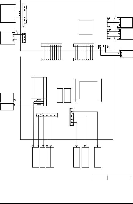
PICTORIAL DIAGRAM
|
|
|
|
|
|
DISPLAY PCB |
|
|
|
|
||||
Touch Panel |
P6 |
|
|
|
|
|
|
|
|
|
|
|
Ribbon |
|
(Membrane |
|
|
|
|
|
|
|
|
|
|
|
|
||
|
|
|
|
|
|
|
|
|
|
|
Cable/3C |
|||
|
|
|
|
|
|
|
|
|
|
|
|
|||
Switch) |
|
|
|
|
|
|
|
|
|
|
|
|
||
|
|
|
|
|
|
|
|
|
|
|
<![if ! IE]> <![endif]>1 |
<![if ! IE]> <![endif]>CN701 |
|
|
|
<![if ! IE]> <![endif]>1 |
|
|
|
|
|
|
|
|
|
|
Inverter |
||
|
|
|
|
|
|
|
|
|
|
|
|
P2 |
|
1100W |
|
|
|
|
|
|
|
|
|
|
|
|
|
|
|
Ribbon |
|
|
|
|
|
|
|
|
|
MCU |
|
|
<![if ! IE]> <![endif]>1 |
|
Cable/4C |
|
|
|
|
|
|
|
|
|
|
|
|
|
|
P7 |
|
|
|
|
|
|
|
|
|
|
<![if ! IE]> <![endif]>1 |
1 CN151 |
|
|
|
|
|
|
|
|
|
|
|
|
|
Inverter |
|||
P7 |
|
|
|
|
|
|
|
|
|
|
|
P3 |
|
40W |
|
|
|
|
|
|
|
|
|
|
|
|
|
||
External |
|
|
|
|
|
|
|
|
|
|
|
|
|
|
Keyboard |
<![if ! IE]> <![endif]>1 |
|
|
|
|
P11 |
|
|
|
P21 |
|
|
Ribbon |
|
| <![if ! IE]> <![endif]>1 |
|
|
|
|
|
|
|
|
P5 |
|
||||
|
|
|
|
|
|
|
|
|
|
|
|
Cable/4C |
||
|
|
|
|
|
|
|
|
|
|
|
|
1 |
||
|
|
|
|
|
|
|
|
|
|
|
|
|
|
|
|
|
|
|
|
|
|
|
|
|
|
|
|
Red |
|
|
|
|
|
|
|
|
|
|
|
|
|
|
Black |
|
|
|
|
|
|
|
|
|
|
|
|
|
|
Humidity |
|
|
|
|
|
|
|
|
|
|
|
|
|
|
White |
Sensor |
|
|
|
|
|
|
|
|
|
|
|
|
|
|
|
|
|
|
|
|
|
P11 |
|
|
|
P21 |
|
|
|
|
|
|
|
|
|
|
POWER PCB |
|
|
|
|
||||
|
|
4903 |
|
|
|
|
|
|
L.V.T. |
|
|
|
|
|
|
|
MW |
|
|
|
|
|
|
|
|
|
|
||
|
|
|
|
|
|
|
|
TR1 - 5101 |
|
|
|
|||
|
|
RELAY |
|
|
|
|
|
|
|
|
|
|||
Interlock |
|
|
|
|
|
|
|
|
|
|
|
|
||
|
|
|
|
|
4906 |
4901 |
|
|
|
|
|
|
|
|
Secondary |
Red |
|
|
|
|
|
|
|
|
|
|
|
|
|
Switch |
|
2 |
|
|
|
|
|
|
|
|
|
|
|
|
|
|
|
|
|
|
|
|
|
|
|
|
|
||
1100W |
Red |
|
1 |
|
|
|
|
|
|
|
|
|
|
|
|
|
|
|
|
|
|
|
|
|
|
|
|
||
|
|
|
|
|
|
|
|
|
|
|
|
|
|
|
Inverter |
|
|
|
|
|
|
|
<![if ! IE]> <![endif]>1 |
|
|
|
|
|
|
|
|
|
|
|
|
|
P12 |
|
|
|
|
|
|
|
|
|
|
|
|
P14 |
|
|
|
|
|
|
|
||
|
|
|
|
|
|
|
|
|
|
|
|
|
||
|
|
1 |
|
|
|
|
|
|
|
|
|
|
|
|
|
<![if ! IE]> <![endif]>Orange |
<![if ! IE]> <![endif]>Orange |
<![if ! IE]> <![endif]>Blue |
|
<![if ! IE]> <![endif]>Red |
<![if ! IE]> <![endif]>Gray |
|
|
|
|
|
|
|
|
|
|
|
|
|
|
|
|
<![if ! IE]> <![endif]>Yellow |
|
<![if ! IE]> <![endif]>Brown |
<![if ! IE]> <![endif]>Green |
|
|
|
|
<![if ! IE]> <![endif]>Fuse |
<![if ! IE]> <![endif]>0.25 Amp. |
<![if ! IE]> <![endif]>Magnetron |
<![if ! IE]> <![endif]>Thermostat |
<![if ! IE]> <![endif]>TT Motor |
<![if ! IE]> <![endif]>Stirrer Motor |
|
<![if ! IE]> <![endif]>Exhaust fan |
<![if ! IE]> <![endif]>Thermostat |
<![if ! IE]> <![endif]>Fuse 4 Amp. |
<![if ! IE]> <![endif]>Fuse |
<![if ! IE]> <![endif]>4 Amp. |
|
|
|
|
|
|
|
|
|
|
|
|
|
DWG. No. L-M1-054 Rev. A |
|||
PART NO. 4619-651-97964/8184640 |
FOR SERVICE TECHNICIAN'S USE ONLY |
 Loading...