


Operation instructions • english |
1923640E |
Gebrauchsanweisung • deutsch |
0544 |
Gebruiksaanwijzing • nederlands |
|
Manuel d’utilisation • français |
|
PROMIG
520R, 120R

CONTENTS |
|
1. PREFACE ...................................................................................................................... |
3 |
1.1. INTRODUCTION......................................................................................................... |
3 |
1.2 PRODUCT INTRODUCTION ....................................................................................... |
3 |
1.3. OPERATION SAFETY................................................................................................. |
4 |
2. INSTALLATION.............................................................................................................. |
5 |
2.1. OPERATION CONTROL AND CONNECTORS .......................................................... |
5 |
2.1.1. PROMIG 520R CONTROL UNIT ................................................................... |
5 |
2.1.2. PROMIG 120R WIRE FEEDER..................................................................... |
6 |
2.2. UNITS, ACCESSORIES, CABLES.............................................................................. |
7 |
2.3. PARTS OF WIRE FEED MECHANISM....................................................................... |
8 |
2.4. ASSEMBLY OF MIG SYSTEM.................................................................................... |
9 |
3. INSTALLATION OF MIG SYSTEM.............................................................................. |
10 |
3.1. ACCESSORIES CORRESPONDING TO WIRE DIAMETER.................................... |
10 |
3.2. MOUNTING OF MIG GUN......................................................................................... |
11 |
3.3. AUTOMATIC WIRE FEED TO GUN........................................................................... |
11 |
3.4. ADJUSTMENT OF PRESSURE................................................................................. |
11 |
3.5. BURN BACK TIME.................................................................................................... |
12 |
3.6. GROUND CABLE...................................................................................................... |
12 |
3.7. SHIELD GAS............................................................................................................. |
12 |
3.7.1. INSTALLING GAS BOTTLE......................................................................... |
12 |
3.8. MAIN SWITCH I/O..................................................................................................... |
13 |
3.9. OPERATION OF COOLING UNIT ............................................................................ |
13 |
4. CONTROL PANEL OPERATIONS .............................................................................. |
13 |
4.1. MC CONTROL PANEL ............................................................................................. |
13 |
4.1.1. WELD DATA / GAS TEST ............................................................................ |
15 |
4.1.2. SELECTO OPERATIONS, MC PANEL........................................................ |
16 |
4.2. ML CONTROL PANEL .............................................................................................. |
17 |
4.2.1. WELD DATA................................................................................................. |
20 |
4.2.2. SYNERGIC OPERATIONS, ML PANEL....................................................... |
21 |
4.3. MXE CONTROL PANEL ........................................................................................... |
23 |
5. OTHER USER FUNCTIONS........................................................................................ |
24 |
6. ERROR CODES OF PANELS ..................................................................................... |
24 |
7. SERVICE AND OPERATION DISTURBANCES ......................................................... |
25 |
8. DISPOSAL OF THE MACHINE ................................................................................... |
25 |
9. ORDERING NUMBERS............................................................................................... |
26 |
11. TERMS OF GUARANTEE ......................................................................................... |
28 |
2 – PROMIG 520R, 120R / 0544 |
© KEMPPI OY |

1. PREFACE
1.1. INTRODUCTION
Congratulations on having purchased this product. Properly installed Kemppi products should prove to be productive machines requiring maintenance at only regular intervals. This manual is arranged to give you a good understanding of the equipment and its safe operation. It also containsmaintenanceinformationandtechnicalspecifications.Readthismanualfromfronttoback before installing, operating or maintaining the equipment for the first time. For further information on Kemppi products please contact us or your nearest Kemppi distributor.
Specifications and designs presented in this manual are subject to change without prior notice.
In this document, for danger to life or injury the following symbol is used: 
Readthewarningtextscarefullyandfollowtheinstructions.PleasealsostudytheOperationsafety instructions and respect them when installing, operating and servicing the machine.
1.2 PRODUCT INTRODUCTION
Promig 520R is a welding system designed for robotic and automated welding. It consists of Promig 520R with inbuilt robot interface and a robot arm mounted feed unit Promig 120R. These two units are connected with an intermediate cable assembly.
Manual control is possible using interchangeable control panels:
MC: basic controls and displays for MIG welding, Five pre-selectable memory channels.
ML: basic controls and displays for MIG welding, Synergic MIG / Pulsed MIG welding modes.
MXE: SynergicMIG/MAGandPulsedMIGinthemostdemandingweldingenvironment.MMA welding is also possible.
Welding operation is controlled by microprocessor. The wire feed motor includes an amplified tachometer feedback system to ensure accurate wire feed speed. The interface stage handles 37 I/O signals covering all automated requirements.
There are three models of PROMIG 520 R. Each model has different versions according to the robot type.
1)PROMIG 520 R – basic model is to be used with control panels ML and MC.
2)PROMIG 520 R –MXE is designed for use with MXE panel. MXE has 63 memory channels.
3)PROMIG 520R–SWFutilises(insteadofPROMIG120R)anexternalvoltagecontrolled wire feeding unit.
© KEMPPI OY |
PROMIG 520R, 120R / 0544 – 3 |

1.3. OPERATION SAFETY
Please study these Operation safety instructions and respect them when installing, operating and servicing the machine.
Welding arc and spatters
Welding arc hurts unprotected eyes. Be careful also with reflecting arc flash. Welding arc and spatter burn unprotected skin. Use safety gloves and protective clothing.
Danger for fire or explosion
Pay attention to fire safety regulations. Remove flammable or explosive materials from welding place. Always reserve sufficient fire-fighting equipment on welding place. Be prepared for hazards in special welding jobs, e.g. for the danger of fire or explosion when welding container type work pieces. Note! Fire can break out from sparks even several hours after the welding work has been finished!
Mains voltage
Never take welding machine inside a work piece (eg. container or truck). Do not place welding machineonawetsurface.Alwayscheckcablesbeforeoperatingthemachine.Changedefectcables without delay. Defect cables may cause an injury or set out a fire. Connection cable must not be compressed, it must not touch sharp edges or hot work pieces.
Welding power circuit
Isolate yourself by using proper protective clothing, do not wear wet clothing. Never work on a wet surface or use defect cables. Do not put MIG gun or welding cables on welding machine or on other electric equipment. Do not press MIG gun’s switch, if the gun is not directed towards a work piece.
Welding fumes
Take care that there is sufficient ventilation during welding. Take special safety precautions when welding metals which contain lead, cadmium, zinc, mercury or beryllium.
4 – PROMIG 520R, 120R / 0544 |
© KEMPPI OY |
2. INSTALLATION
2.1. OPERATION CONTROL AND CONNECTORS
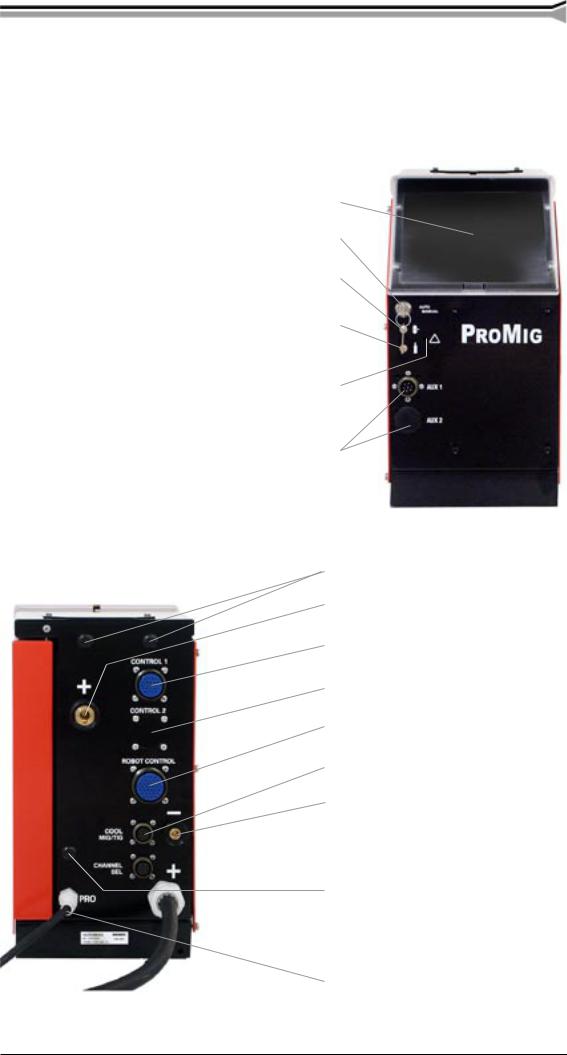
2.1.1. Promig 520R control unit
Place for control panel
Lock switch of panel (option for MXE model)
Wire inch
Gas purge
Motor overcurrent indicator
Holes for user connectors
Holes for gas snap connectors
Welding current output connector (+)
Control cable connector (to 120R or voltage controlled wire feeder SWF)
Control cable connector (to 2nd 120R) Robot controller connector
Control cable connector (Probus)
Voltage monitoring connector (–)
Connector for channel selection
 (option for MXE model)
Hole for wire outlet connector
 Fixed welding cable to Pro power source
Fixed control cable to Pro power source
© KEMPPI OY |
PROMIG 520R, 120R / 0544 – 5 |
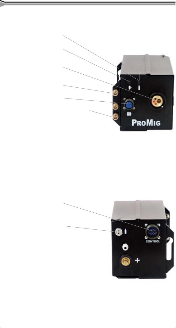
2.1.2. Promig 120R wire feeder
Gas purge
Wire inch
Euro connector for robot gun
Snap connector for air blast
Connector for motorised gun
Snap connectors for  cooling liquid
Control cable connector
Snap connector for gas
Wire liner inlet 
Welding current cable connector 
6 – PROMIG 520R, 120R / 0544 |
© KEMPPI OY |
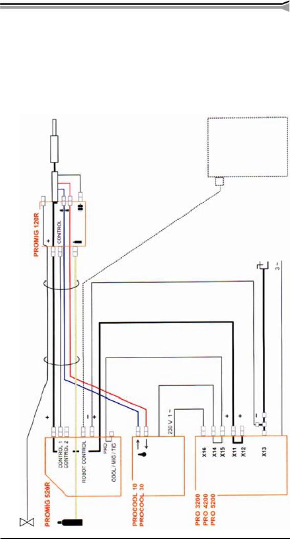
2.2. UNITS, ACCESSORIES, CABLES
Airhose Intermediatecable |
assembly Airblast Shieldinggashose Coolingliquidhoses Controlcable Controlcable Weldingcurrentcable Voltagemonitorcable Branchconnector Earthcable Robotcontrol |
A B |
C D E F G H I J K L |
L
C
K
I
B
H
G
F
E
J
A
D
© KEMPPI OY |
PROMIG 520R, 120R / 0544 – 7 |

2.3. PARTS OF WIRE FEED MECHANISM
8 – PROMIG 520R, 120R / 0544 |
© KEMPPI OY |
2.4. ASSEMBLY OF MIG SYSTEM
Assemble the units according to the mounting instructions delivered with the unit.
1. Installation of power source
Read paragraph “INSTALLATION” in operation instructions for PRO power sources and install accordingly.
2. Mounting of PRO power source to transport wagon
P 20 see air-cooled MIG system P 30W see liquid-cooled MIG system P 40 see air-cooled MIG system
3.Put PROMIG onto the power source and lock it with bolts to handles of power source.
4.Mounting of PROMIG control panel
MC |
6263501 |
see mounting instructions 4270950 |
ML |
6263502 |
see mounting instructions 4270950 |
MXE |
6263504 |
see mounting instructions 4279220 |
5. Connecting cables
Connect cables according to paragraph ”UNITS, ACCESSORIES, CABLES”.
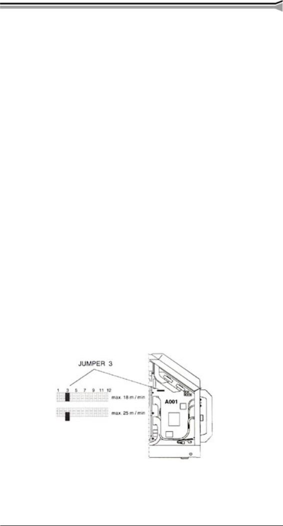
6. Max. wire feed speed
By delivery, the max. wire feed speed is 18 m/min, which is enough for most welding applications. If you need a higher speed, you can increase the wire feed speed to 25 m/min by replacing the gear wheel on motor shaft. The high ratio wheel (*D40*) is delivered with the feed unit.
Changing the maximum wire feed speed:
–OpensideplateandremoveJUMPER3oncontrolcardA001.Thisaltersthetacho feedback ratio to 0 - 25 m/min.
© KEMPPI OY |
PROMIG 520R, 120R / 0544 – 9 |
 Loading...