


DT400

1920130
0808
Käyttöohje • Suomi
Bruksanvisning • Svenska
Bruksanvisning • Norsk
Brugsanvisning • Dansk
Operating manual • English
Gebrauchsanweisung • Deutsch
KEMPARC™
Gebruiksaanwijzing • Nederlands
Manuel d’utilisation • Français
Manual de instrucciones • Español
Instrukcja obsługi • Polski
Инструкции по эксплуатации • По-русски
SYN 300
SYN 400
SYN 500
DT 400
FI
SV
NO
DA
EN
DE
NL
FR
ES
PL
RU


KempArc SYN 300, 400, 500 / © Kemppi Oy / 0808
OPERATING MANUAL
English
FI
SV
NO
DA
EN
EN
DE
NL
FR
ES
PL
RU

CONTENTS
FI
SV
NO
DA
KempArc SYN 300, 400, 500 / © Kemppi Oy / 0808
1. PREFACE ......................................................................................
1.1 General .................................................................................................................................................................3
1.2 Safety Instructions .......................................................................................................................................3
1.3 Introduction .....................................................................................................................................................5
2. USE ...............................................................................................6
2.1 Power source
2.1.1 Power source components ...............................................................................................................6
2.1.2 Locating the power source ...............................................................................................................6
2.1.3 Connecting the power source to the electric network ...........................................................7
2.1.4 Connecting the cables ........................................................................................................................8
2.1.5 Installing the eld bus card ..............................................................................................................9
2.1.6 Starting the power source..............................................................................................................10
2.1.7 Power source indicators ..................................................................................................................10
2.2 Control panel
2.2.1 Control panel parts ...........................................................................................................................10
2.2.2 Adjusting MIG dynamics (Arc Force) ..........................................................................................11
2.2.3 Gas test ..................................................................................................................................................11
2.2.4 Wire feed test ...................................................................................................................................... 11
2.2.5 Selection of liquid- or gas-cooled MIG gun .............................................................................12
2.2.6 Retrieving weld data ........................................................................................................................12
2.2.7 Selecting the welding process .....................................................................................................12
2.2.8 Additional MIG features included in the standard delivery ............................................... 12
2.2.9 Optional additional MIG features ................................................................................................14
2.2.10 Memory features (MEMORY button) ..........................................................................................14
2.2.11 Synergetic 1-MIG welding and AAA-MIG welding ................................................................15
2.2.12 SETUP features of the control panel ........................................................................................... 17
2.3 Wire feeder ..................................................................................................................................................... 18
...................................................................................................................................................6
................................................................................................................................................10
3. MAINTENANCE .........................................................................19
3.1 Cables .................................................................................................................................................................19
3.2 Power source ................................................................................................................................................20
3.2.1. DuraTorque™ 400, 4-wheel wire feeder mechanism ............................................................20
3.3 Regular maintenance .............................................................................................................................21
3.4 Disposal of the machine .......................................................................................................................21
3
EN
EN
DE
NL
FR
ES
PL
RU
4. TROUBLESHOOTING ................................................................21
4.1 Overload (yellow indicator lit)
4.2 Control cable connector fuse
4.3 Electric network overvoltage or undervoltage ...................................................................21
4.4 Missing phase in the electric network
4.5 Error codes
......................................................................................................................................................22
..........................................................................................................21
...........................................................................................................21
.......................................................................................22
5. ORDERING NUMBERS .............................................................. 23
6. TECHNICAL DATA ..................................................................... 23
7. WARRANTY POLICY ..................................................................25
2

1. PREFACE
1.1 GENERAL
Congratulations on your choice of the Kemparc™ SYN-series welding system. Reliable
and durable, Kemppi products are aordable to maintain, and they increase your work
productivity.
This user manual contains important information on the use, maintenance and safety of
your Kemppi product. The technical specications of the device can be found at the end of
the manual. Please read the manual carefully before using the equipment for the rst time.
For your safety and that of your working environment, pay particular attention to the safety
instructions in the manual.
For more information on Kemppi products, contact Kemppi Oy, consult an authorised Kemppi
dealer, or visit the Kemppi Web site at www.kemppi.com.
The specications presented in this manual are subject to change without prior notice.
NOTE! Items in the manual that require particular attention in order to minimise damage and
personal harm are indicated with this symbol. Read these sections carefully and follow their
instructions.
1.2 SAFETY INSTRUCTIONS
Kemppi welding devices conform to international safety standards. Safety is an important
issue in equipment design and manufacturing. Therefore, Kemppi welding solutions are
unparalleled in safety. There are, however, always certain hazards involved in using welding
equipment. Therefore, to ensure your personal safety and the safety of your working
environment, carefully read the safety instructions below and respect them.
Use of personal protective equipment
• The arc and its reecting radiation damage unprotected eyes. Shield your eyes and
face appropriately before you start welding or observe welding. Also note the dierent
requirements for the darkness of the screen in the mask as the welding current changes.
• The arc radiation and spatters burn unprotected skin. Always wear protective gloves,
clothing and footwear when welding.
• Always wear hearing protection if the ambient noise level exceeds the allowable limit
(e.g., 85 dB).
General operating safety
• Exercise caution when handling parts heated in welding. For example, the tip of the
welding torch, the end of the welding rod and the work piece will heat during gouging to
a burning temperature.
• Never wear the device on the shoulder during welding and never suspend it by the
carrying strap during welding.
• Do not expose the machine to high temperatures, as this may cause damage to the
machine.
• Keep the torch cable and earthing cable as close to each other as possible throughout
their length. Straighten any loops in the cables. This minimises your exposure to harmful
magnetic elds, which may interfere with a pacemaker, for example.
• Do not wrap the cables around the body.
• In environments classied as dangerous, only use S-marked welding devices with a safe
idle voltage level. These work environments include, for example, humid, hot or small
spaces where the user may be directly exposed to the surrounding conductive pieces.
Spatter and re safety
• Welding is always classied as hot work, so pay attention to re safety regulations during
welding and after it.
• Remember that re can break out from sparks even several hours after the welding work
is completed.
FI
SV
NO
DA
EN
EN
DE
NL
FR
ES
PL
KempArc SYN 300, 400, 500 / © Kemppi Oy / 0808
RU
3

KempArc SYN 300, 400, 500 / © Kemppi Oy / 0808
• Protect the environment from welding spatter. Remove ammable materials, such as
ammable uids, from the welding vicinity and supply the welding site with adequate re
ghting equipment.
• In special welding jobs, be prepared for hazards such as re or explosion when welding
container-type work pieces.
• Never direct the spark spray or cutting spray of a grinder toward the welding machine or
ammable materials.
• Beware of hot objects or spatter falling on the machine when working above the machine.
• Welding in ammable or explosive sites is absolutely forbidden.
General electric safety
• Only connect the welding machine to an earthed electric network.
• Note the recommended mains fuse size.
• Do not take the welding machine inside a container, vehicle or similar work piece.
• Do not place the welding machine on a wet surface and do not work on a wet surface.
• Do not allow the mains cable to be directly exposed to water.
• Ensure cables or welding torches are not squashed by heavy objects and that they are not
exposed to sharp edges or a hot work piece.
• Make sure that faulty and damaged welding torches are changed immediately as they can
be lethal and may cause electrocution or re.
• Remember that the cable, plugs and other electric devices may be installed or replaced
only by an electrical contractor or engineer authorised to perform such operations.
• Turn o the welding machine when it is not in use.
Welding power circuit
• Insulate yourself from the welding circuit by using dry and undamaged protective
clothing.
• Never touch the work piece and welding rod, welding wire, welding electrode or contact
tip at the same time.
• Do not put the welding torch or ground cable on the welding machine or other electric
equipment.
FI
SV
NO
DA
EN
EN
DE
NL
FR
ES
PL
RU
Welding fumes
• Ensure proper ventilation and avoid inhaling the fumes.
• Ensure sucient supply of fresh air, particularly in closed spaces. You can also ensure the
supply of clean and sucient breathing air by using a fresh-air mask.
• Take extra precautions when working on metals or surface-treated materials containing
lead, cadmium, zinc, mercury or beryllium.
Transportation, lifting and suspension
• Never pull or lift the machine by the welding torch or other cables. Always use the lift
points or handles designed for that purpose.
• Only use a transport unit designed for the equipment.
• Try to transport the machine in an upright position, if possible.
• Never lift a gas cylinder and the welding machine at the same time. There are separate
provisions for gas cylinder transportation.
• Never use a welding machine when suspended unless the suspension device has been
designed and approved for that particular purpose.
• Do not exceed the maximum allowed load of suspension beams or the transportation
trolley of welding equipment.
• It is recommended that the wire coil be removed during lifting or transportation.
Environment
• Protect welding machines from heavy rain and direct sunshine even if it were suitable for
outdoor use.
• Always store the machine in a dry and clean space.
• Protect the machine from sand and dust during use and in storage.
• The recommended operating temperature range is -20 to +40 °C. The machine’s operation
eciency decreases and it becomes more prone to damage if used in temperatures in
excess of 40 °C.
• Place the machine so that it is not exposed to hot surfaces, sparks or spatter.
4

• Make sure the airow to and from the machine is unrestricted.
• This electromagnetic compatibility (EMC) of professional equipment is usually designed
for industrial use. Such class-A equipment is not intended for use in residential locations
where the electrical power is provided by the public low-voltage supply system. The
machine may interfere with sensitive home electronic devices.
Gas bottles and pneumatic devices
• Adhere to the instructions for handling pneumatic devices and gas bottles.
• Make sure that gas bottles are used and stored in properly ventilated spaces. A leaking gas
bottle may replace the oxygen in the inhaled air, causing suocation.
• Before use, make sure that the gas bottle contains gas suitable for the intended purpose.
• Always x the gas cylinder securely in an upright position, against a cylinder wall rack or
purpose-made cylinder cart.
• Never move a protective gas bottle when the ow adjuster is in place. Put the valve cover
in place during transportation.
• Close the cylinder valve after use.
1.3 INTRODUCTION
KempArc™ SYN is a product family for welding automation that includes all welding devices
needed in robot welding. The KempArc™ SYN welding system includes the following devices:
• KempArc™ SYN 300, SYN 400 and SYN 500 are synergetic welding power sources
designed particularly for welding automation that are suitable for MIG welding with direct
current. There are three power types of power sources: the 300, 400 and 500 ampere
models. For more information on using power sources and their functions, see "Power
source".
• RF 59 is a control panel that contains the programs and welding parameters needed
in controlling the welding hardware. The panel functions allow the user to control the
operation of the welding hardware and adjust its welding settings. The control panel is
located in the front panel of the welding power source. For more information on using the
control panel and its functions, see "Control panel".
• KempArc™ DT 400 is a wire feeding device that feeds welding wire to the welding robot
at the speed it requires at any time. For more information on using the wire feeder and its
functions, see "Wire feeder".
This guide presents the functions, operation and technical properties of the above devices.
The devices also include the KempArc™ Cool 10 cooler, but its functions and features are
presented in a separate guide.
The KempArc™ Synergic hardware is connected to the welding robot control system with the
control unit on top of the power source.
KempArc SYN 300, 400, 500 / © Kemppi Oy / 0808
FI
SV
NO
DA
EN
EN
DE
NL
FR
ES
PL
RU
5
2. USE
2.1 POWER SOURCE
2.1.1 Power source components
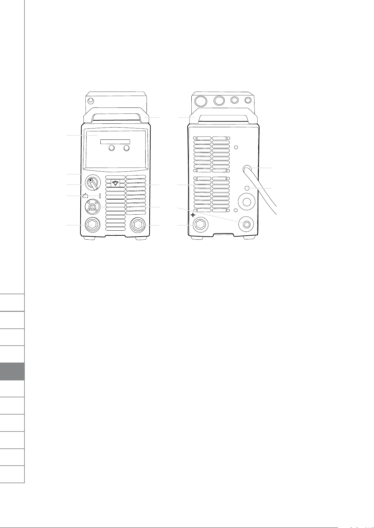
A1
A3
A2
KempArc SYN 300, 400, 500 / © Kemppi Oy / 0808
A4
A11
A10
A7
1 2 3 4
A8
A9
FI
SV
NO
DA
EN
EN
DE
NL
FR
ES
PL
A6
A1 Control panel
A2 Main switch
A3 Signal light (I/O)
A4 Thermal warning light
A5 Welding cable connection (parallel)
A6 Earthing cable connection
A7 Control cable connection (parallel)
A8 Mains cable
A9 Fuse for control cable connection (6.3 A slow)
A10 Fan grill
A11 Transportation handles
2.1.2 Locating the power source
Place the machine on a sturdy, level surface that is dry and does not release dust or other
impurities to the suction air through the fan grill.
Notes for positioning of the machine
• Preferably, place the machine somewhat above oor level.
• The surface inclination may not exceed 15 degrees.
• There must be at least 20 cm of free space in front of and behind the machine for cooling
air circulation.
• Protect the machine against heavy rain and direct sunshine.
• Ensure the free circulation of the cooling air.
The protection class of the machine, IP23C, allows water spray to hit the machine’s outer
covering at a maximum angle of 60 degrees.
NOTE! Never aim the spray of sparks from a grinding machine toward the power source.
A5
1 Robot Control
2 Wire Feeder
3 Throughput
4 Analog
RU
6

2.1.3 Connecting the power source to the electric network
The KempArc™ SYN power source is connected to a 400-V three-phase network. The machine
is equipped with a ve-metre mains cable that does not have a plug. Before use, check the
mains cable and install a mains plug. If the cable does not comply with the local electrical
regulations, replace it with a compliant cable.
NOTE! The mains cable or plug may be installed or replaced by only an electrical contractor or
installer authorised to perform such operations.
Replacement of the mains cable
1. Unscrew the mounting screws on the top and sides of the machine, and remove the case
by lifting it.
2. Disconnect the phase leads from connectors L1, L2, and L3, and disconnect the protective
earth lead.
3. Pass the cable to the machine through the inlet ring at the rear of the machine, and secure
the cable with a cable clamp.
4. Connect the cable’s phase leads to connectors L1, L2, and L3.
5. Connect the yellow-green protective earth lead to its connector .
NOTE! Do not connect the zero lead if you are using a ve-lead cable.
The table below lists the fuse sizes for 100% load in a 400-V three-phase network with
4 x 6-mm² cable for dierent power source models.
Model Fuse
SYN 300 20 A delayed
SYN 400 25 A delayed
SYN 500 35 A delayed
KempArc SYN 300, 400, 500 / © Kemppi Oy / 0808
FI
SV
NO
DA
EN
EN
DE
NL
FR
ES
PL
RU
7
 Loading...