


Kempomat 2500, 3200, 4200
Operating manual • English
Käyttöohje • Suomi
Bruksanvisning • Svenska
Bruksanvisning • Norsk
Brugsanvisning • Dansk
Gebrauchsanweisung • Deutsch
Gebruiksaanwijzing • Nederlands
Manuel d’utilisation • Français
Manual de instrucciones • Español
Instrukcja obsługi • Polski
EN
FI
SV NO DA DE NL FR ES PL
Инструкции по эксплуатации • По-русски RU

English |
manual Operating |
Kempomat 2500, 3200, 4200 / © Kemppi Oy / 1117

Kempomat 2500, 3200, 4200 / © Kemppi Oy / 1117
EN
Contents |
|
||
1. |
|
PREFACE......................................................................................................................................................... |
3 |
1.1 |
General................................................................................................................................................................. |
3 |
|
1.2 |
Product introduction.................................................................................................................................. |
3 |
|
2. |
Installation of the power source............................................................ |
4 |
|
2.1 |
Positioning of the machine................................................................................................................... |
4 |
|
2.2 |
Connection to the mains supply....................................................................................................... |
4 |
|
2.3 |
Mounting of the mains cable............................................................................................................... |
4 |
|
2.4 |
Welding and return current cables.................................................................................................. |
5 |
|
3. |
|
Use of wirefeeder..................................................................................................................... |
6 |
3.1 |
Parts of wire feed mechanism............................................................................................................. |
6 |
|
3.2 |
Installation of the wire feed system................................................................................................ |
8 |
|
3.3 |
Installation of wire feed............................................................................................................................ |
8 |
|
3.4 |
Mounting of MIG welding gun........................................................................................................... |
9 |
|
3.5 |
Mounting and locking of wire reel................................................................................................... |
9 |
|
3.6 |
Automatic wire feed to gun............................................................................................................... |
10 |
|
3.7 |
Adjustment of tightness of wire reel brake............................................................................ |
10 |
|
3.8 |
Shielding gas................................................................................................................................................. |
11 |
|
4. |
Operation and use of power source.................................................. |
12 |
|
4.1 |
Kempomat panels..................................................................................................................................... |
12 |
|
4.2 |
Wire feed panel............................................................................................................................................ |
13 |
|
4.3 |
Wire feeder unit........................................................................................................................................... |
13 |
|
4.4 |
Main switches and pilot lamps........................................................................................................ |
14 |
|
4.5 |
Adjustment for arc roughness.......................................................................................................... |
15 |
|
4.6 |
Operation of cooling fan...................................................................................................................... |
15 |
|
5. |
Control panels and adjustments.......................................................... |
15 |
|
5.1 |
Wire feed speed potentiometer...................................................................................................... |
15 |
|
5.2 |
Burn back time............................................................................................................................................. |
15 |
|
5.3 |
KMW timer functions.............................................................................................................................. |
16 |
|
6. |
|
Accessories....................................................................................................................................... |
17 |
6.1 |
KMW sync........................................................................................................................................................ |
17 |
|
6.2 |
Installation and mounting of KMW sync.................................................................................. |
17 |
|
7. |
|
Operation disturbances........................................................................................... |
18 |
8. |
Regular maintenance of the equipment..................................... |
18 |
|
8.1 |
Cables................................................................................................................................................................. |
19 |
|
8.2 |
Power source................................................................................................................................................. |
19 |
|
8.3 |
Disposal of the machine....................................................................................................................... |
19 |
|
9. |
|
ORDERING NUMBERS............................................................................................................... |
20 |
10. |
TECHNICAL DATA........................................................................................................................... |
21 |
|
2

1.PREFACE
1.1General
Congratulations on choosing the Kempomat™ equipment. Used correctly, Kemppi products can significantly increase the productivity of your welding, and provide years of economical service.
This operating manual contains important information on the use, maintenance and safety of your Kemppi product. The technical specifications of the equipment can be found at the end of the manual.
Please read the manual carefully before using the equipment for the first time. For your own safety and that of your working environment, pay particular attention to the safety instructions in the manual.
For more information on Kemppi products, contact Kemppi Oy, consult an authorised Kemppi dealer, or visit the Kemppi web site at www.kemppi.com.
The specifications presented in this manual are subject to change without prior notice.
Important notes
Items in the manual that require particular attention in order to minimise damage and personal harm are indicated with the ’NOTE!’ notation. Read these sections carefully and follow their instructions.
Disclaimer
While every effort has been made to ensure that the information contained in this guide is accurate and complete, no liability can be accepted for any errors or omissions. Kemppi reserves the right to change the specification of the product described at any time without prior notice. Do not copy, record, reproduce or transmit the contents of this guide without prior permission from Kemppi.
1.2Product introduction
The power sources Kempomat 3200 and 4200 are compact MIG welding machines, designed for heavy industrial use. Kempomat 2500 is compact MIG welding machine, designed for repair shops and light and heavy industrial use.
Power source
Supply voltage of the Kempomat 2500 power source is 3~ 230 V/400 V. Supply voltage of the Kempomat 3200 power source is 3~ 230 V/400 V. Welding voltage adjustment is in 10-steps. Adjustment for voltage of power source is in 40-steps.
In Kempomat 4200 product range there are different units for mains voltages 3~ 230 and 400 V. The welding voltage adjustment for 230 V power source is made in 32 steps, 400V power source in 56-steps. The Volt/Ampere metering unit MSD 1 (available as accessory) displays voltage or welding current.
Wire feeder unit
The wire feeder unit is a fixed unit in the equipment for air-cooled guns. Kempomat 2500 is equipped with 2 wheel wire drive mechanism, Kempomat 3200 and 4200 are equipped with 4 wheel wire drive mechanism. Accessory unit KMW sync is needed for connection and use of push-pull guns.
3
Kempomat 2500, 3200, 4200 / © Kemppi Oy / 1117
EN
Kempomat 2500, 3200, 4200 / © Kemppi Oy / 1117
EN
2.Installation of the power source
2.1Positioning of the machine
Place the machine on a firm, dry and level surface. Where possible, do not allow dust or other impurities to enter the machines cooling air flow. Preferably site the machine above floor level; for example on a suitable carriage unit.
Notes for positioning the machine
•The surface inclination should not exceed 15 degrees.
•Ensure the free circulation of the cooling air. There must be at least 20 cm of free space in front of and behind the machine for cooling air to circulate.
•Protect the machine against heavy rain and direct sunshine.
Note! The machine should not be operated in the rain as the protection class of the machine, IP23S, allows for outside preserving and storage only.
Note! Never aim metallic grinding spray/sparks towards the equipment.
2.2Connection to the mains supply
Connection and change of the mains cable and the plug must be carried out only by a competent electrician. Remove for the mounting of the mains cable the left side plate, seen from the front of the power source.
The Kempomat power source is equipped with 5 m supply cable without plug. The mains cable is according to the marking H07RN-F of the norm CENELEC HD22. The mains cable must be changed if it doesn´t meet local regulations.
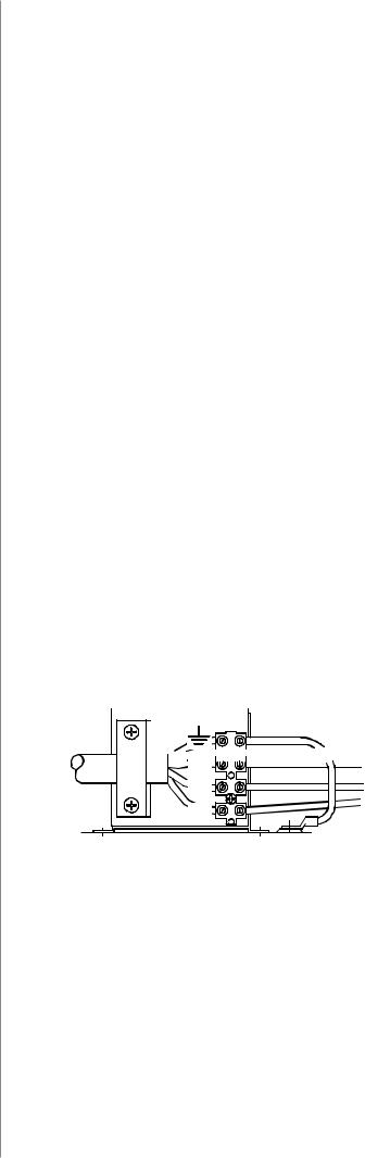
2.3Mounting of the mains cable
The cable is entered into the machine through the inlet ring on the rear wall of the machine and locked with a cable clamp (05).
The phase conductors of the cable are coupled to connectors L1, L2 and L3. The earth protection coloured green-yellow is coupled to connector marked with earth protection symbol  . If you are using 5-conductor cable, you must cut the zero conductor to the level of the cable´s protective shield.
In cables of S type there is protective grounding conductor coloured green-yellow.

 L1
L1 


L2 |
L3 |
Kempomat |
2500 |
|
3200 |
|
4200 |
|
Connection voltage |
230 V |
400 V |
230 V |
400 V |
230 V |
400 V |
Connection cable |
4G2.5 (5 m) |
4G2.5 (5 m) |
4G2.5 (5 m) |
4G2.5 (5 m) |
4G6.0 (5 m) |
4G2.5 (5 m) |
|
|
|
|
|
|
|
Fuse, delayed |
16 A |
10 A |
20 A |
16 A |
25 A |
16 A |
4
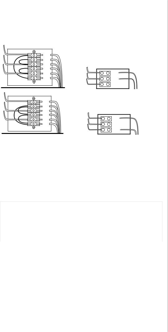
Change of mains voltage / Kempomat 2500, 3200
Connection and change of the mains cable and the plug must be carried out only by a competent electrician.
230 V |
201 |
|
|
|
|
|
|
|
204 |
|
230 V |
|
203 |
|
|
|
|
|
|
|
206 |
|
0 |
|
205 |
T002 |
|
|
202 |
230 V |
|
|
|
||
|
|
|
400 V |
400 V |
201 |
|
|
204 |
|
400 V |
|
|
203 |
|
|
|
|
|
|
|
206 |
|
0 |
|
205 |
|
|
|
T002 |
|
|
|
202 |
230 V |
|
|
|
|
400 V |
Connection 3~ 230 or 3~ 400 V of mains voltage
By delivery from the factory the Kempomat 3200 and 2500 machine has been connected for mains voltage 3~ 400 V. In order to change the mains voltage in the Kempomat 2500/3200 machine, remove the side plate of the machine. Change the connections according to the enclosed diagram. You find the corresponding wiring diagram on the instruction label, which is under terminal block.
Note! The Kempomat 4200 machine has the connection for only one mains voltage!
2.4Welding and return current cables
In enclosed table are shown typical loading capacities of rubber insulated copper cables, when ambient temperature is 25 °C and conductor temperature is 85 °C.
Kempomat 2500
Cable cross-section |
|
Duty cycle ED |
|
Voltage loss / 10 m |
Cu |
100 % |
60 % |
30 % |
for 100 A |
|
|
|
|
|
25 mm² |
180 A |
230 A |
330 A |
0.7 V |
35 mm² |
225 A |
290 A |
410 A |
0.5 V |
|
|
|
|
|
Kempomat 3200, 4200 |
|
|
|
|
Cable cross-section |
|
Duty cycle ED |
|
Voltage loss / 10 m |
Cu |
100 % |
60 % |
40 % |
for 100 A |
|
|
|
|
|
50 mm² |
285 A |
370 A |
450 A |
0.35 V |
70 mm² |
355 A |
460 A |
560 A |
0.25 V |
|
|
|
|
|
NOTE! Don´t overload welding cables over permissible values due to voltage losses and heating. Fasten the earthing press of the return current cable carefully, preferably direct onto the piece to be welded. The contact surface area of the press should always be as large and steady as possible. Clean the contact surface from paint and rust.
5
Kempomat 2500, 3200, 4200 / © Kemppi Oy / 1117
EN

Kempomat 2500, 3200, 4200 / © Kemppi Oy / 1117
EN
3.Use of wirefeeder
3.1Parts of wire feed mechanism
Kempomat 2500
Wire guide tubes for 2-roll wire feed mechanism
Wire ø mm |
Wire guide tube ø mm |
|
|
|
|
|
|
|
|
|
|
|
|
|||
Fe, Mc, |
0,6 ... 0,8 |
White |
1,0 |
3134140 |
|
|
|
|
brass |
4285900 |
|
|
|
1,8 |
plastic |
4102283 |
|
|
|
|
|
|
|
||||||||||
Fc |
|
|
|
|
|
|
|
|
|
|
|
|
|
|
|
|
0,9 ... 1,6 |
Orange |
2,0 |
3133700 |
|
|
|
|
|
|
|
|
|
|
|
|
|
|
|
|
|
|
|
|
|
|
|
|
|
|
||||
Ss, Al |
0,8 ... 1,6 |
Silver |
2,5 |
3134290 |
|
|
|
|
|
|
|
|
|
|
|
|
|
|
|
|
|
|
|
|
|
|
|
|
|||||
|
|
A. |
|
|
|
|
|
|
B. |
|
|
|
|
C. |
|
|
|
|
|
|
|
|
|
|
|
|
|
|
|
|
|
|
|
|
|
|
|
|
|
|
|
|
|
|
|
|
|
|
|
|
A. |
B. |
Pressure adjustment |
|
|
|
|
|
||
|
C. |
Gear wheel, 2-roll wire feed mechanism |
||
|
|
|||
|
|
ø 28 mm (0–18 m/min) |
4265240 |
muovi |
|
|
ø 28 mm (0–18 m/min) |
4287860 |
teräs |
Feed rolls |
2-roll (2500) |
|
|
|
|
Colour |
ø mm |
|
|
Fe, Ss, Al |
White |
0.6/0.8 |
3133810 |
|
Plain V-groove |
White |
0.8/0.8 (L) |
3143180 |
|
Red |
|
3133210 |
||
|
|
|||
|
|
|
|
|
|
Red |
1.0/1.0 (L) |
3138650 |
|
|
|
|
|
|
|
Orange |
1.2/1.2 (L) |
3137390 |
|
|
Yellow |
1.4-1.6 |
3133820 |
|
|
|
|
|
|
|
Yellow |
1.6/1.6 (L) |
3141120 |
|
|
|
|
|
|
|
|
|
|
|
Fe, Fc, Mc |
Red |
1.0/1.2 |
3133940 |
|
Knurled |
Orange |
1.2/1.2 (L) |
3137380 |
|
|
|
|
||
Yellow |
1.4-1.6 |
3133990 |
||
V-groove |
||||
|
|
|
||
|
Yellow |
1.6/1.6 (L) |
3141130 |
|
|
|
|
|
|
|
|
|
|
|
Fe, Fc, Mc, |
Orange |
1.2/1.2 (L) |
3142210 |
|
Ss, Al |
Brown |
1.4/1.4 (L) |
3142220 |
|
|
||||
|
|
|
|
|
Trapezoid |
Yellow |
1.6/1.6 (L) |
3142200 |
|
|
|
|
||
groove |
|
|
|
|
|
|
|
|
|
(L) = Fitted with ball bearings |
|
|
||
2500, 3200, 4200
Feed roll groove selection
Transfer of gear wheel selector plate
6
 Loading...