


MXF 63
FastMig
MXF 63, 65, 67
Operating manual
Brugsanvisning
Gebrauchsanweisung
Manual de instrucciones
Käyttöohje
Manuel d’utilisation
Manuale d’uso
Gebruiksaanwijzing
Bruksanvisning
Instrukcja obsługi
Manual de utilização
EN
DA
DE
ES
FI
FR
IT
NL
NO
PL
PT
Инструкции по эксплуатации
Bruksanvisning
操作手册
RU
SV
ZH


OPERATING MANUAL
English

EN
CONTENTS
1. Preface ........................................................................................................... 3
1.1 General ....................................................................................................................................... 3
1.2 About FastMig products ...................................................................................................... 3
2. Installation .................................................................................................... 4
2.1 Machine introduction, MXF 65, MXF 67 and MXF 63 ................................................ 4
2.2 Connection of system ........................................................................................................... 5
2.3 Assembly of MIG/MAG system .......................................................................................... 6
2.4 Accessories corresponding to wire diameter ..............................................................7
2.5 Welding gun selection .......................................................................................................... 7
2.6 Mounting and locking of wire spool ............................................................................... 7
2.7 Loading the ller wire and automatic feed ..................................................................8
2.8 DuraTorque™ 400, 4-wheel wire feed mechanism ..................................................... 8
2.9 Wire liners ................................................................................................................................10
2.10 Adjustment of pressure arms ...........................................................................................11
2.11 Adjustment of spool brake ...............................................................................................11
2.12 Burn back time ......................................................................................................................11
2.13 Earth return cable .................................................................................................................11
2.14 Shielding gas ..........................................................................................................................12
2.15 Main switch I/O .....................................................................................................................13
2.16 Operation of cooling unit, FastCool 10 ........................................................................13
2.17 MXF hanging kit ....................................................................................................................14
3. Control panel operations ........................................................................15
3.1 Connecting and mounting ...............................................................................................15
4. Welding software delivery prole ........................................................ 16
5. Panel button functions ...........................................................................19
5.1 PF 63 and PF 65 control panel for FastMig Pulse ...................................................... 19
5.2 PF 63 and PF 65 control panel button functions ......................................................20
5.3 SF 51 and 54 control panel for FastMig KMS ..............................................................23
5.4 SF 52W and 53W control panel for FastMig KMS .....................................................24
5.5 MS 200 and MS 300 control panel for FastMig M ..................................................... 25
5.6 MR 200 and MR 300 control panel for FastMig M ....................................................26
6. Basic troubleshooting ............................................................................. 27
7. Maintenance .............................................................................................. 28
7.1 Daily maintenance ...............................................................................................................28
7.2 Service shop maintenance ...............................................................................................28
8. Disposal of the machine ......................................................................... 28
9. Ordering numbers .................................................................................... 29
10. Technical data ............................................................................................ 33
2
FastMig MXF 63, 65, 67

1. PREFACE
1.1 General
Congratulations on choosing the FastMig MXF equipment. Used correctly, Kemppi products
can signicantly increase the productivity of your welding, and provide years of economical
service.
This operating manual contains important information on the use, maintenance and safety of
your Kemppi product. The technical specications of the equipment can be found at the end
of the manual.
Please read the operating manual and the safety instructions booklet carefully before using
the equipment for the rst time. For your own safety and that of your working environment,
pay particular attention to the safety instructions in the manual.
For more information on Kemppi products, contact Kemppi Oy, consult an authorised Kemppi
dealer, or visit the Kemppi web site at www.kemppi.com.
The specications presented in this manual are subject to change without prior notice.
Important notes
Items in the manual that require particular attention in order to minimise damage and
personal harm are indicated with the ’NOTE!’ notation. Read these sections carefully and follow
their instructions.
Disclaimer
While every eort has been made to ensure that the information contained in this guide
is accurate and complete, no liability can be accepted for any errors or omissions. Kemppi
reserves the right to change the specication of the product described at any time without
prior notice. Do not copy, record, reproduce or transmit the contents of this guide without
prior permission from Kemppi.
EN
1.2 About FastMig products
Kemppi FastMig™ MXF 63, MXF 65 and MXF 67 are wire feeders designed for demanding
professional use. MXF 63 is intended for 200 mm wire spool, MXF 65 and MXF 67 for 300 mm
wire spool. Wire feeders can be used with FastMig Pulse, FastMig KMS and FastMig M power
sources.
Which alternative panel to choose for MXF 63, 65 and 67 depends on the used power source
i.e. FastMig KMS becomes compatible by connecting SF 51, SF 52W, SF 53W or SF 54 control
panels with MXF wire feed unit, and in the case of PF 63 and PF 65 control panels FastMig
Pulse power source can be connected. With FastMig M the MR 200, MR 300, MS 200 or MS 300
panels are used. Operation of wire feed units is controlled and adjusted by microprocessor. By
adding an optional synchronization unit (MXF Sync 65), SuperSnake sub-feeder device may be
connected to MXF 63, 65 and 67.
This manual provides instructions on the start-up and use of the MXF 63, 65 and 67 MIG/MAG
wire feeding units.
© Kemppi Oy / 1515
3
2. INSTALLATION
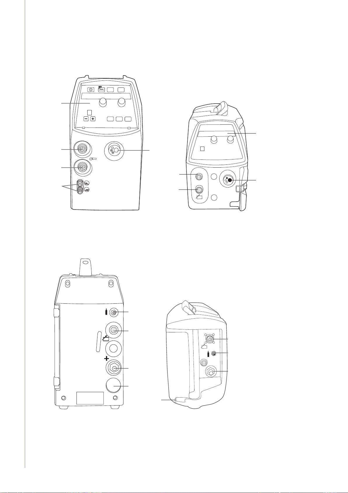
2.1 Machine introduction, MXF 63, MXF 65 and MXF 67
WF #
1.
1.
EN
3.
2.
4.
1. Control panel
2. Remote control connector
3. Sub-feeder sync connector (kit optional)
4. Gun water connections (cooling optional)
5. Euro gun connector
6.
5.
3.
5.
2.
4
6. Shielding gas connection
7. Connection for control cable
8. Welding current cable connector
9. Lead-in and clamping of cooling liquid hoses
FastMig MXF 63, 65, 67
7.
7.
6.
8.
9.
9.
8.
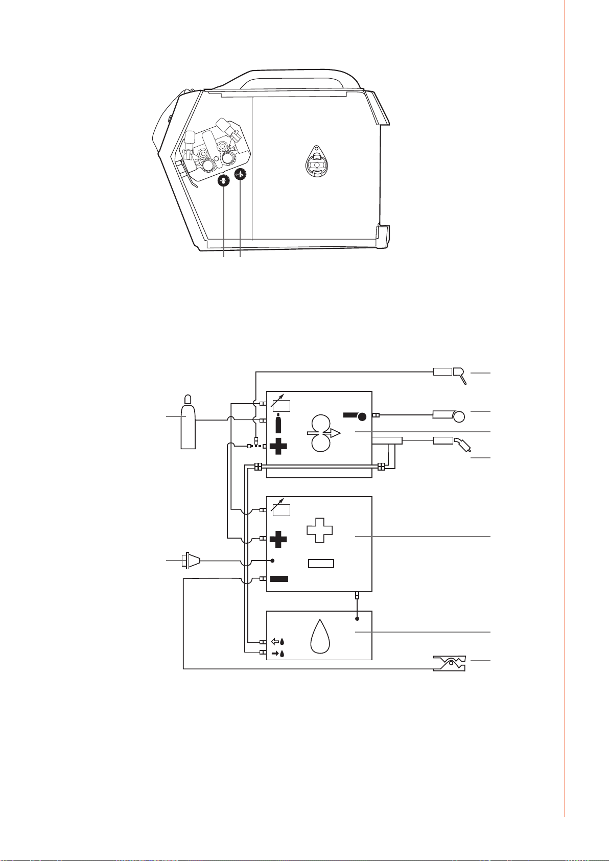
10. 11.
10. Wire Inch button
11. Gas Test button
2.2 Connection of system
2.2.1 Liquid cooled system: FastMig power source + MXF + FastCool 10
EN
5.
4.
8.
1. MXF wire feed unit
2. FastMig power source
3. FastCool water cooler and power connection
4. Gas supply
5. MMA electrode holder
6. Remote control device
7. Liquid cooled welding Gun
8. Power cable
9. Earth return lead and clamp
6.
1.
7.
2.
3.
9.
© Kemppi Oy / 1515
5
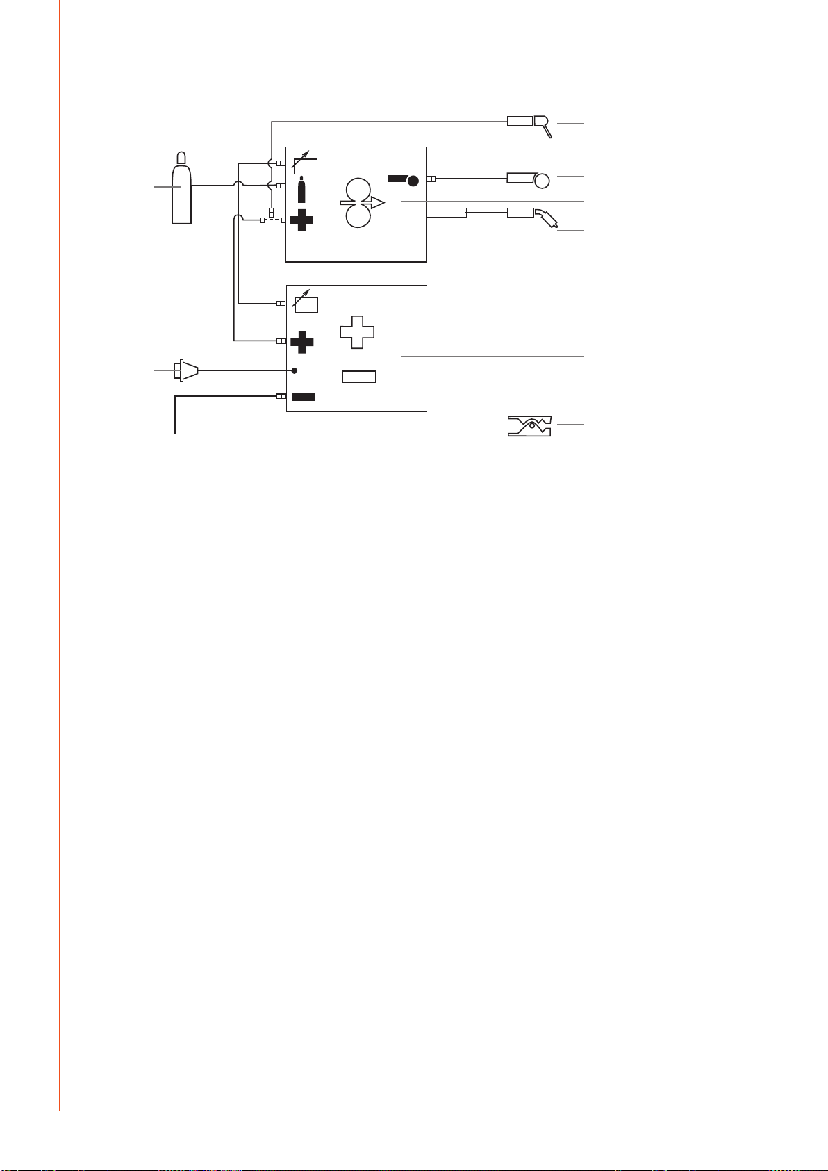
2.2.2 Air cooled system: FastMig power source + MXF
4.
EN
3.
7.
1. MXF wire feed unit
2. FastMig power source
3. Gas supply
4. MMA electrode holder
5. Remote control device
6. Air cooled welding gun
7. Power cable
8. Earth return lead and clamp
5.
1.
6.
2.
8.
2.3 Assembly of MIG/MAG system
Assemble the units in the order mentioned below. Follow the additional mounting and
operating instructions delivered with each package.
1. Installation of power source
Read paragraph: ”Installation” in the operation instructions for FastMig power sources, and
complete the installation according to that advice.
2. Mounting of power sources to transport wagon
Read and follow the instructions given in the transport cart installation/assembly manual.
3. Mounting the FastMig MXF wire feed unit to the power source
Remove the cover sticker on top of the power source. Screw the fastening pivot into the
power source – hand tighten only. Place the supplied plastic spacers over the pivot. Lift the
MXF wire feeder into place, locating over the pivot.
4. Connecting cables
Connect the cables in accordance with the equipment notes provided in this manual.
The polarity of the welding wire (+ or –) can be selected by connecting the wire feed unit to
either the positive or the negative power source terminals.
Most MIG/MAG applications run the wire feed unit connected to the positive terminal of the
power source.
5. Mounting FastMig wire feed units to boom and swing arms
When mounting wire feed units to boom and swing arms, the unit must be electrically
isolated from both.
Suspension angle of wire feed unit can be changed by moving the xing point in handle.
6
FastMig MXF 63, 65, 67
2.4 Accessories corresponding to wire diameter
Colour coded wire feed rolls and guide tubes are available to suit a variety of ller wire types
and sizes. Drive roll groove geometry and design vary depending on the application. Further
details are available in the spare part tables.
Please ensure you select the correct drive rolls and guide tubes from the table to suit your
particular welding application.
2.5 Welding gun selection
Please ensure that the welding gun selected is suitable for the target application. Check the
gun manufacturer's specication and ensure the gun meets the welding duty requirements.
Also consider the extra heating eects of Pulse MIG/MAG welding on the gun selected.
Kemppi gun products are designed to meet many dierent applications. Special wire liners
and contact tips are available for dierent wire types and sizes.
Distance wire feeding is accommodated with WeldSnake and SuperSnake products in either
air or liquid cooled models.
Thermal and load protection is also designed to some Kemppi Gun models and feed units, so
carefully consider your requirements and consult your local Kemppi sales team to ensure you
choose the correct alternative for your needs.
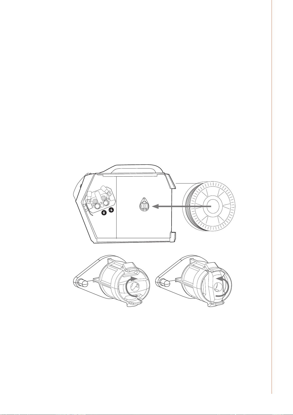
2.6 Mounting and locking of wire spool
EN
NOTE! Check that the ller wire spool is correctly mounted and locked into position. Ensure the
spool is not damaged or deformed in such a way that it can rub or cha against the internal
surface of the wire feed unit chassis or door. This may result in increased drag, impacting on weld
quality. This may also result in long term wire feed unit damage, rendering the unit unserviceable
or unsafe to use.
© Kemppi Oy / 1515
7
2.7 Loading the ller wire and automatic feed
Automatic wire feed makes wire spool changes faster. When changing the wire spool, the
pressure of feed rolls need to be released.
Simply ensure that the groove of the feed roll matches the diameter of ller wire used. Release
the wire end from the spool and cut o any deformed section. Be careful the wire does not
spill from the spool sides.
Straighten about 20 cm of ller wire and ensure the tip has no sharp edges. File if necessary, as
a sharp wire edge may damage the wire gun liner - particularly softer plastic liners.
Present the ller wire tip to the back of the wire feed rolls and press the Wire Inch button on
the wire feed panel or use the switch inside the wire spool cabinet. Feed the wire to the gun
contact tip and prepare to weld.
NOTE! Smaller diameter ller wires may need to be loaded manually – with the feed roll pressure
arms released. This is because it is easy to overestimate the pressure required to feed these smaller
ller wires. Too high feed roll pressures can easily deform ller wires and contribute to later feeding
problems.
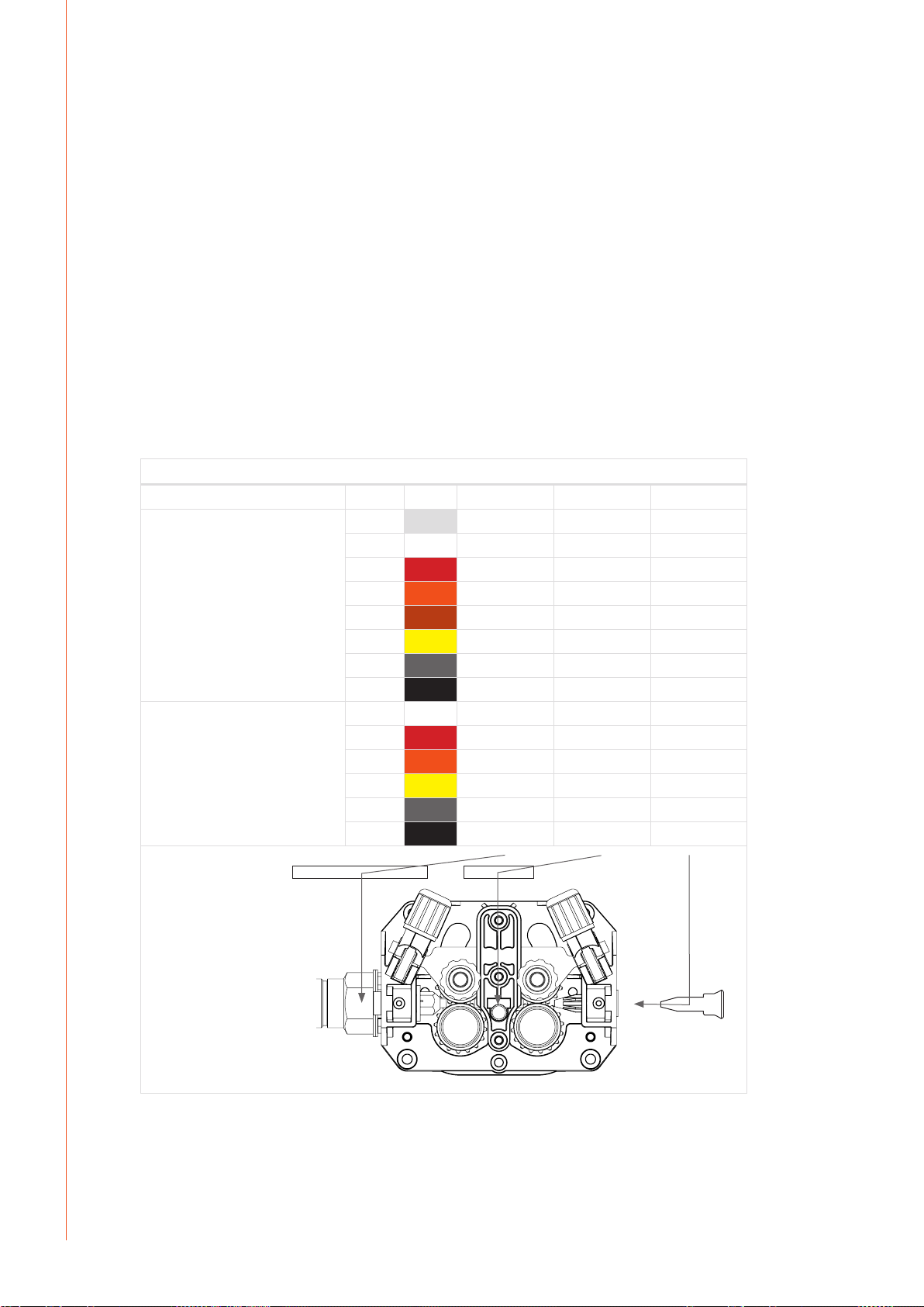
2.8 DuraTorque™ 400, 4-wheel wire feed mechanism
EN
Wire guide tubes
Ss, Al,
(Fe, Mc, Fc)
plastic
Fe, Mc, Fc
metal
ø mm outlet tube middle tube inlet tube
0.6 W007437 W007429 W007293
0.8 – 0.9 W007438 W007430 W007294
1.0 W007439 W007431 W007295
1.2 W007440 W007432 W007296
1.4 W007441 W007433 W007297
1.6 W007442 W007434 W007298
2.0 W007443 W007435 W007299
2.4 W007444 W007436 W007300
0.8 – 0.9 W007454 W007465 W007536
1.0 W007455 W007466 W007537
1.2 W007456 W007467 W007538
1.4 – 1.6 W007458 W007469 W007539
2.0 W007459 W007470 W007540
2.4 W007460 W007471 W007541
8
FastMig MXF 63, 65, 67
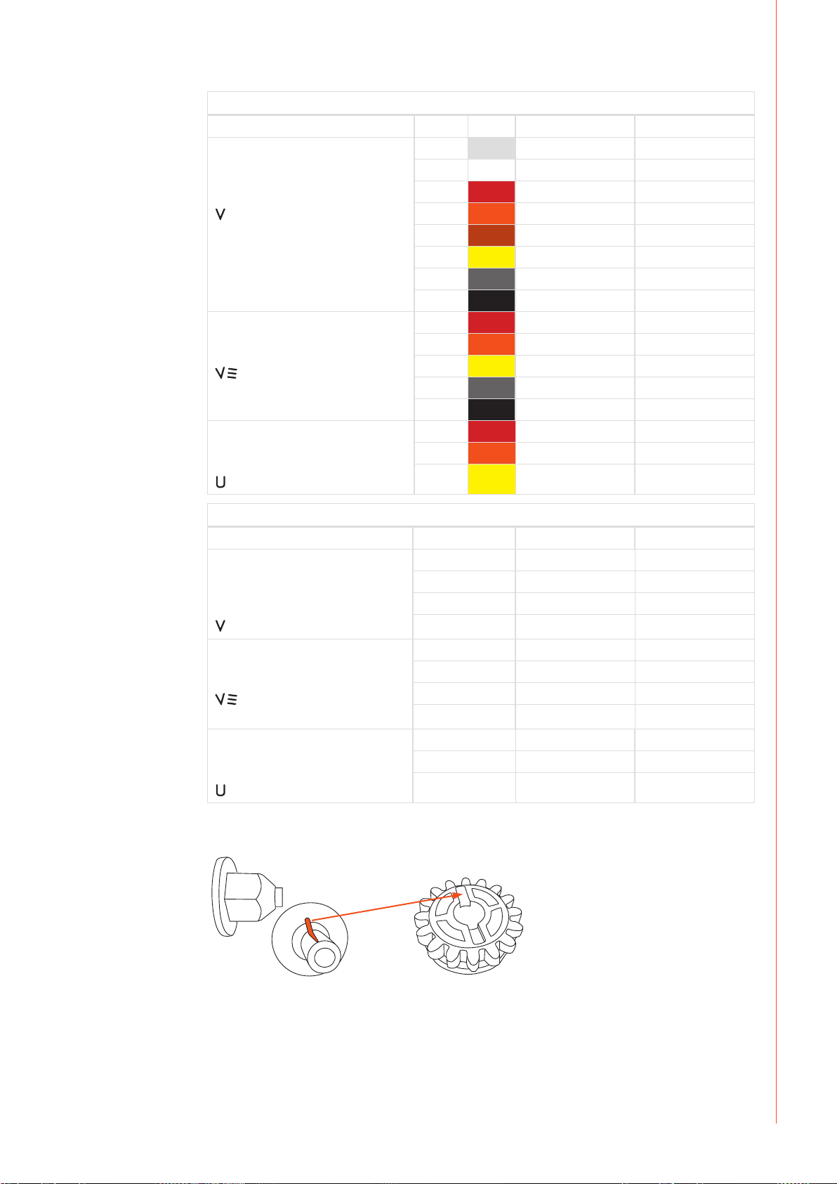
Wire feed rolls, plastic
Fe, Ss,
(Al, Mc, Fc)
V-groove
Fc, Mc, (Fe)
V-groove, knurled
Al, (Fc, Mc, Ss, Fe)
U-groove
ø mm lower upper
0.6 W001045 W001046
0.8 – 0.9 W001047 W001048
1.0 W000675 W000676
1.2 W000960 W000961
1.4 W001049 W001050
1.6 W001051 W001052
2.0 W001053 W001054
2.4 W001055 W001056
1.0 W001057 W001058
1.2 W001059 W001060
1.4 – 1.6 W001061 W001062
2.0 W001063 W001064
2.4 W001065 W001066
1.0 W001067 W001068
1.2 W001069 W001070
1.6 W001071 W001072
EN
Wire feed rolls, metal
ø mm lower upper
Fe, Ss,
(Al, Mc, Fc)
V-groove
Fc, Mc, (Fe)
V-groove, knurled
Al, (Fc, Mc, Ss, Fe)
U-groove
NOTE! Mount the lower feed roll, ensuring that the pin on the shaft ts in the cut on the feed roll.
0.8 – 0.9 W006074 W006075
1.0 W006076 W006077
1.2 W004754 W004753
1.4 W006078 W006079
1.0 W006080 W006081
1.2 W006082 W006083
1.4 – 1.6 W006084 W006085
2.0 W006086 W006087
1.0 W006088 W006089
1.2 W006090 W006091
1.6 W006092 W006093
© Kemppi Oy / 1515
9
 Loading...