


Master MLS 2500, 3500
MasterTig MLS 3000, 4000
MasterCool 10
Operating manual Bruksanvisning Gebrauchsanweisung Manual de instrucciones Käyttöohje Manuel d’utilisation Manuale d’uso Gebruiksaanwijzing Brugsanvisning Instrukcja obsługi
Manual de utilização Инструкции по эксплуатации Bruksanvisning
EN DA DE ES FI FR IT NL NO PL PT RU SV ZH
EN
Operating manual
English

|
Contents |
|
|
|
|
1. |
Preface...................................................................................................................................... |
3 |
|
|
1.1 |
General........................................................................................................................................ |
3 |
|
|
1.2 |
Product introduction............................................................................................................. |
3 |
|
|
2. |
Installation............................................................................................................................. |
4 |
|
|
2.1 |
Removal from packaging..................................................................................................... |
4 |
|
|
2.2 |
Locating the machine............................................................................................................ |
4 |
|
|
2.3 |
Serial number........................................................................................................................... |
4 |
|
|
2.4 |
Installation................................................................................................................................. |
4 |
|
|
2.5 |
Installation of the panel........................................................................................................ |
5 |
|
|
2.6 |
Distribution network............................................................................................................. |
5 |
|
|
2.7 |
Mains connection.................................................................................................................... |
5 |
|
|
2.8 |
Welding cable connections................................................................................................. |
6 |
|
|
|
2.8.1 |
Choosing welding polarity in MMA welding.................................................................. |
6 |
EN |
|
2.8.2 |
Earthing............................................................................................................................. |
6 |
2.9 |
Cooling unit to MasterCool 10........................................................................................... |
6 |
||
|
2.10 |
Shield gas................................................................................................................................... |
8 |
|
|
|
2.10.1 |
Installation of gas bottle.................................................................................................. |
8 |
|
3. |
Operation................................................................................................................................ |
9 |
|
|
3.1 |
Welding processes.................................................................................................................. |
9 |
|
|
|
3.1.1 |
MMA welding................................................................................................................... |
9 |
|
|
3.1.2 |
TIG welding....................................................................................................................... |
9 |
|
|
3.1.3 |
Synergic Pulsed TIG welding (a)...................................................................................... |
9 |
|
|
3.1.4 |
Long Pulsed TIG welding (b)............................................................................................ |
9 |
|
3.2 |
Operation functions............................................................................................................... |
9 |
|
|
|
3.2.1 |
Power source.................................................................................................................... |
9 |
|
|
3.2.2 |
Function panels................................................................................................................ |
9 |
|
|
3.2.3 |
Saving welding settings (MTM)..................................................................................... |
16 |
|
|
3.2.4 |
Adopting the saved settings......................................................................................... |
17 |
|
|
3.2.5 |
Remote control memory channels................................................................................ |
17 |
|
|
3.2.6 |
SETUP functions............................................................................................................. |
17 |
|
|
3.2.7 |
Foot pedal control R11F................................................................................................. |
18 |
|
3.3 |
Cooling unit operation MasterCool 10......................................................................... |
18 |
|
|
3.4 |
Storage...................................................................................................................................... |
18 |
|
|
4. |
Maintenance....................................................................................................................... |
18 |
|
|
4.1 |
Regular maintenance.......................................................................................................... |
18 |
|
|
|
4.1.1 |
Every sixth months......................................................................................................... |
18 |
|
|
4.1.2 |
Service contract.............................................................................................................. |
19 |
|
4.2 |
Troubleshooting.................................................................................................................... |
19 |
|
|
4.3 |
Disposal of the machine..................................................................................................... |
19 |
|
|
5. |
Ordering numbers.......................................................................................................... |
20 |
|
|
6. |
Technical data.................................................................................................................... |
21 |
|
2 Master, MasterTig, MasterCool 10

1.Preface
1.1General
Congratulations on choosing the Master/MasterTig MLS™ equipment. Used correctly, Kemppi products can significantly increase the productivity of your welding, and provide years of
economical service.
This operating manual contains important information on the use, maintenance and safety of your Kemppi product. The technical specifications of the equipment can be found at the end of the manual.
Please read the manual carefully before using the equipment for the first time. For your own safety and that of your working environment, pay particular attention to the safety instructions in the manual.
For more information on Kemppi products, contact Kemppi Oy, consult an authorised Kemppi dealer, or visit the Kemppi web site at www.kemppi.com.
The specifications presented in this manual are subject to change without prior notice.
Important notes
Items in the manual that require particular attention in order to minimise damage and personal harm are indicated with the ’NOTE!’ notation. Read these sections carefully and follow their instructions.
Disclaimer
While every effort has been made to ensure that the information contained in this guide is accurate and complete, no liability can be accepted for any errors or omissions. Kemppi reserves the right to change the specification of the product described at any time without prior notice. Do not copy, record, reproduce or transmit the contents of this guide without prior permission from Kemppi.
1.2Product introduction
Kemppi Master MLS™ 2500 and 3500 is a MMA welding machine designed for industrial use and for welding all kinds of covered electrodes, including difficult-to-weld types such as cellulose electrodes. The equipment consists of power source, welding cables and function panel.
Kemppi Mastertig MLS™ 3000 and 4000 is a TIG welding system especially designed for industrial use and for welding e.g. stainless steel materials. The equipment consists of a power source, function panel, TIG welding torch, ground cable and an optional cooling unit. The cooling unit MasterCool 10 is used in water-cooled TIG welding.
The power source is a multifunctional machine for demanding professional use for MMA, TIG and pulsed TIG welding with direct current. The power source is controlled with IGBT transistors with a frequency of approximately 20 kHz, and the operational functions with a microprocessor. The welding torch can be either water-cooled or gas-cooled.
© Kemppi Oy / 1338
EN
3
EN
4
2.Installation
2.1Removal from packaging
The equipment is packed in durable packages designed especially for it. However, it is necessary to check the equipment before using it to make sure that the equipment or any part of it has not got damaged during transportation. Also check that the delivery corresponds to your order and that you have received all necessary instructions for installing and operating the equipment. The packaging material is recyclable.
2.2Locating the machine
Place the machine on a horizontal, stable and clean ground. Protect the machine from rain and direct sunshine. Check that there is enough space for cooling air circulation in front of and behind the machine.
2.3Serial number
Serial number of the machine is marked on the rating plate. The serial number is the only proper means of identifying parts for a specific product. It is important to make correct reference to the serial number of the product when making repairs or ordering spare parts.
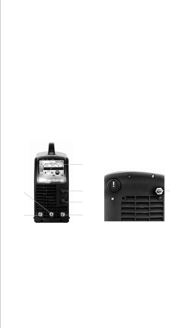
2.4Installation
1
|
|
7 |
|
|
|
|
|
|
|
4 |
2 |
8 |
||
|
3 |
|
|
|
6 |
5 |
|
|
|
1.Function panel
2.Remote control connector
3.TIG torch control connector, not in MMA version
4.Shield gas and current connector for TIG torch, not in MMA version
5.(+) connector for electrode holder or earth cable, in TIG welding for earth cable
6.(-) connector for earth cable or electrode holder in MMA welding (stick welding)
Markings for (+/-) poles on the machine front are embossed.
Rear of machine
7.Mains switch
8.Snap connector for gas
Master, MasterTig, MasterCool 10
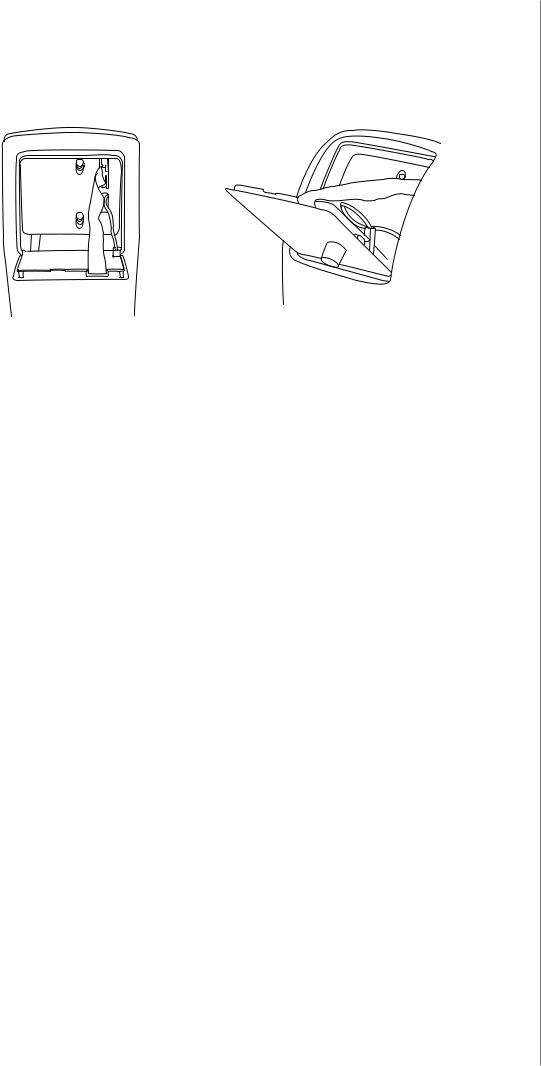
2.5Installation of the panel
1.Fasten the cable connectors of the function panel to the power source (2 pieces).
2.Place the bottom edge of the panel behind the securing clips on the machine. Remove
the fixing pin from the top edge with, for example, a screwdriver. Then gently push the upper part of the panel into place. Make sure that the cables do not get damaged,
continue gently pushing the upper part of the panel until it clips into place. Finally, push the fixing pin back into its place.
2.6Distribution network
All regular electrical devices without special circuits generate harmonic currents into distribution network. High rates of harmonic current may cause losses and disturbance to some equipment.
Master MLS™ 2500, MasterTig MLS™ 3000
This equipment complies with IEC 61000-3-12 provided that the short-circuit power Ssc is greater than or equal to 1.6 MVA at the interface point between the user's supply and the public supply network. It is the responsibility of the installer or user of the equipment to ensure, by consultation with the distribution network operator if necessary, that the
equipment is connected only to a supply with a short-circuit power Ssc greater than or equal to 1.6 MVA.
Master MLS™ 3500, MasterTig MLS™ 4000
This equipment complies with IEC 61000-3-12 provided that the short-circuit power Ssc is greater than or equal to 2.5 MVA at the interface point between the user's supply and the public supply network. It is the responsibility of the installer or user of the equipment to ensure, by consultation with the distribution network operator if necessary, that the
equipment is connected only to a supply with a short-circuit power Ssc greater than or equal to 2.5 MVA.
2.7Mains connection
NOTE! Only an authorised electrician is allowed to install mains cable and plug!
The power source is equipped with a 5-meter mains cable without plug. The fuse and cable sizes are given in the Technical data at the end of this manual.
NOTE! This equipment’s electromagnetic compatibility (EMC) is designed for use in an industrial environment. Class A equipment is not intended for use in residential location where the electrical power is provided by the public low-voltage supply system.
© Kemppi Oy / 1338
EN
5
EN
6
2.8Welding cable connections
2.8.1 Choosing welding polarity in MMA welding
You can change the welding polarity by choosing (+) or (-) cable connector.
2.8.2 Earthing
If possible, always fasten the earth clamp of return current cable directly onto work piece.
1.Clean contact surface of earth clamp from paint and rust.
2.Fasten clamp properly, so that contact surface is as large as possible.
3.Check that clamp is fastened firmly.
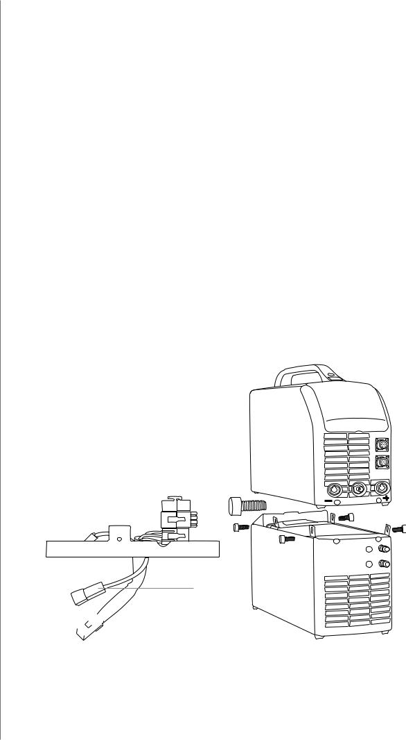
2.9Cooling unit to MasterCool 10
NOTE! Cooling liquid is injurious! Avoid also contact with skin or eyes. In case of injury, seek for medical advice.
Cooling unit MasterCool 10 together with TIG torch of Kemppi’s TTC-W range enables TIG welding with water-cooled torch.
The cooling unit is installed beneath the power source with screws. Electrical connections are on the bottom of power source. Fill the reservoir with a 20 - 40 % mixture of etanol and water, or with any other suitable antifreeze. The capacity of the reservoir is 3 litres.
MasterCool 10:
Mastertig MLS 3000
Mastertig MLS 4000
Installation of cooling unit
2.
 1.
1.
Master, MasterTig, MasterCool 10

Installing gas-cooled torch
Installing water-cooled torch
Connect the red water hose to the upper connector and blue one to the lower connector..
© Kemppi Oy / 1338
EN
7
 Loading...